

Page 1
Model 2081 pH
Smart Microprocessor
Analyzer
Instruction Manual
PN 5102081P
November 2000
FREE
EXTENDED
WARRANTY!
(See offer at back of manual)
Page 2

ESSENTIAL INSTRUCTIONS
READ THIS PAGE BEFORE PROCEEDING!
SS-2081
Feb. 1992
Rosemount Analytical designs, manufactures, and
tests its products to meet many national and international standards. Because these instruments are
sophisticated technical products, you must properly install, use, and maintain them to ensure they
continue to operate within their normal specifications. The following instructions must be adhered to
and integrated into your safety program when
installing, using, and maintaining Rosemount
Analytical products. Failure to follow the proper
instructions may cause any one of the following situations to occur: Loss of life; personal injury; property damage; damage to this instrument; and warranty invalidation.
• Read all instructions prior to installing, operating,
and servicing the product. If this Instruction
Manual is not the correct manual, telephone 1800-654-7768 and the requested manual will be
provided. Save this Instruction Manual for future
reference.
• If you do not understand any of the instructions,
contact your Rosemount representative for clarification.
• Follow all warnings, cautions, and instructions
marked on and supplied with the product.
• Inform and educate your personnel in the proper
installation, operation, and maintenance of the
product.
• Install your equipment as specified in the
Installation Instructions of the appropriate
Instruction Manual and per applicable local and
national codes. Connect all products to the proper electrical sources.
• To ensure proper performance, use qualified personnel to install, operate, update, program, and
maintain the product.
• When replacement parts are required, ensure
that qualified people use replacement parts
specified by Rosemount. Unauthorized parts and
procedures can affect the product’s performance
and place the safe operation of your process at
risk. Look alike substitutions may result in fire,
electrical hazards, or improper operation.
• Ensure that all equipment doors are closed and
protective covers are in place, except when maintenance is being performed by qualified persons,
to prevent electrical shock and personal injury.
Rosemount Analytical Inc.
Uniloc Division
2400 Barranca Parkway
Irvine, CA 92606 USA
Tel: (949) 863-1181
1-800-854-8257
www.RAuniloc.com
© Rosemount Analytical Inc. 1999
Page 3

MODEL 2081 pH
MICROPROCESSOR TRANSMITTER
TABLE OF CONTENTS
Section Title Page
1.0 INSTALLATION....................................................................................................... 1
1.1 Unpacking and Inspection...................................................................................... 1
1.2 Mechanical Installation............................................................................................ 1
1.3 Wiring ...................................................................................................................... 1
1.4 Jumper Settings ...................................................................................................... 2
1.5 Hazardous Locations - Explosion Proof Installations .............................................. 3
1.6 Hazardous Locations - Intrinsically Safe Installations............................................. 3
2.0 QUICK START-UP PROCEDURE........................................................................... 11
2.1 General.................................................................................................................... 11
2.2 Set-Up Instrument ................................................................................................... 11
2.3 Temperature Standardization .................................................................................. 12
2.4 Two-Point Calibration .............................................................................................. 13
2.5 Current Output Check ............................................................................................. 14
3.0 DESCRIPTION OF CONTROLS............................................................................. 15
3.1 General.................................................................................................................... 15
3.2 Menu Selection........................................................................................................ 15
3.3 Value Adjustment .................................................................................................... 15
4.0 RANGE CONFIGURATION .................................................................................... 16
5.0 START UP AND CALIBRATION ............................................................................ 17
5.1 General.................................................................................................................... 17
5.2 Temperature Calibration.......................................................................................... 17
5.3 Buffer Calibration .................................................................................................... 17
5.4 pH Standardization ................................................................................................. 18
5.5 pH Glass Slope ....................................................................................................... 18
5.6 Hold Mode for Maintenance.................................................................................... 19
5.7 Sensor Maintenance ............................................................................................... 19
6.0 KEYBOARD SECURITY......................................................................................... 20
7.0 THEORY OF OPERATION ..................................................................................... 21
8.0 DIAGNOSTICS AND TROUBLESHOOTING.......................................................... 22
8.1 Diagnostics ............................................................................................................. 22
8.2 Troubleshooting....................................................................................................... 22
9.0 DESCRIPTION AND SPECIFICATIONS ................................................................ 26
9.1 Features .................................................................................................................. 26
9.2 Functional Specifications ........................................................................................ 27
9.3 Performance Specifications .................................................................................... 27
9.4 Physical Specifications ........................................................................................... 27
9.5 Recommended Sensors.......................................................................................... 28
9.6 Ordering Information ............................................................................................... 28
9.7 Model 2081 pH Replacement Parts and Accessories ............................................ 29
10.0 RETURN OF MATERIALS...................................................................................... 30
i
MODEL 2081 pH TABLE OF CONTENTS
Page 4

TABLE OF CONTENTS CONT’D.
LIST OF FIGURES
Figure No. Title Page
1-1 Model 2081 pH Power and Sensor Wiring.............................................................. 4
1-2 Sensor Wiring Details for use with 2081 pH............................................................ 5
1-3 Model 2081 pH Jumper Settings ............................................................................ 6
1-4 BASEEFA Label for Instrinsically Safe Installation .................................................. 6
1-5 Explosion Proof System Installation Schematic (FM) .............................................. 7
1-6 Intrinsically Safe System Installation Schematic (FM) Page 1 of 2 ......................... 8
1-7 Intrinsically Safe System Installation Schematic (FM) Page 2 of 2 ......................... 9
1-8 Intrinsically Safe System Installation Schematic (CSA)........................................... 10
2-1 Wiring Setup............................................................................................................ 11
2-2 Button Use............................................................................................................... 12
3-1 Menu Description.................................................................................................... 15
6-1 Model 2081 pH Jumper Settings ............................................................................ 20
8-1 Bench Check with preamp...................................................................................... 25
8-2 Bench Check without preamp................................................................................. 25
LIST OF TABLES
Table No. Title Page
8-1 Fault Mnemonics..................................................................................................... 22
8-2 RTD Resistance Values ........................................................................................... 22
8-3 Sensor Input V. pH at Four Temperatures ............................................................... 23
8-4 Voltage Input to Transmitter .................................................................................... 23
8-5
Troubleshooting Guide ............................................................................................ 24
ii
MODEL 2081 pH TABLE OF CONTENTS
Page 5

1.1 UNPACKING AND INSPECTION. Inspect the
transmitter for shipping damage. If damaged, notify
the carrier immediately. Confirm that all items shown
on the packing list are present. Notify Rosemount
Analytical if items are missing. If the transmitter
appears to be in satisfactory condition proceed to
Section 1.2.
NOTE
Save the original packing cartons and
materials as most carriers require proof of
damage due to mishandling.
1.2 MECHANICAL INSTALLATION.
1.2.1 General. The transmitter may be installed in
harsh environments. However, it should be installed in
an area where sources of extreme temperature fluctuation, vibration and shock are at a minimum or absent.
Select an installation site that (1) permits the use of the
standard cable lengths (unless a J-box is used), (2) is
easily accessed by operating and maintenance personnel, and (3) is at least 12 inches (.3 m) from
sources of high voltage.
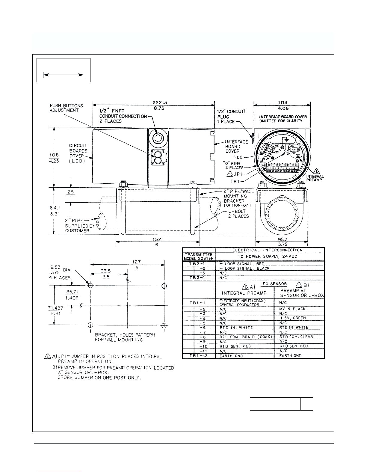
1.2.2 Mounting. The transmitter may be mounted on
a flat surface using the two threaded mounting holes
located on the bottom of the transmitter or through the
use of an optional 2-inch pipe/wall mounting bracket,
Code 07 (Figur
e 1-1).
NOTE
The meter may be installed in 90-degree increments for easy viewing. Remove the four screws
holding the meter in place and change the
meter to the desired angle. Plug in the display
and tighten the four screws.
1.3 WIRING. The transmitter is equipped with two 1/2-
inch NPT conduit openings, one on each side of the
housing. One is for the power supply/signal wiring and
the other is for the sensor wiring.
To prevent moisture from entering the housing, the use
of weathertight cable glands or conduit is recommended. If conduit is used, it should be positioned to
prevent condensation from draining into the housing.
Conduit connections on the transmitter housing should
be plugged and sealed to avoid moisture accumulation
in the terminal side of the housing.
CAUTION
If the connections are not sealed, the
transmitter should be mounted with the
electrical housing positioned downward
for drainage. Wiring should be installed
with a drip loop, and the bottom of the drip
loop should be lower than the conduit connections or the transmitter housing.
The signal wiring should be twisted pairs for best
results. The twisted pairs should also be shielded and
grounded. The best place to ground the loop is at the
negative terminal of the power supply. Do not ground
the signal loop in more than one point. The transmitter
case shall be grounded.
Signal or sensor wiring should never be run in the
same conduit or open tray as AC power or relay actuated signal cables. Keep signal or sensor wiring at
least 12 in. (.3 m) from heavy electrical equipment.
NOTE
For best EMI/RFI protection the output cable
should be shielded and enclosed in an earth
grounded rigid metal conduit. Connect the
cable’s outer shield to the ground terminal
provided next to TB2, Figur
e 1-1.
The sensor cable should also be shielded.
Connect this outer shield to earth ground as in
the instructions above. If the outer shield is
braided an appropriate metal cable gland fitting may be used to connect the outer braid to
earth groud via the instrument case.
1
SECTION 1.0 INSTALLATION
MODEL 2081 pH SECTION 1.0
INSTALLATION
Page 6

2
NOTE
For RFI/EMI protection, the power
supply/signal wiring and sensor wiring must
be shielded, preferably in metal conduit,
and the shields terminated to earth ground.
1.3.1 Sensor Wiring. The sensor wiring terminals are
located on the side of the housing opposite of the LCD
meter. Remove the housing cover to gain access to the
terminals. Pass the sensor cable through the transmitter’s
conduit opening. Connect the sensor wiring to TB1 terminals 1 through 12 as shown on Figure 1-1.
NOTE
Sensors are supplied with a standard
cable length of 10 feet (3.0 m) or 15 feet
(4.5 m). If the standard cable length is not
sufficient for the planned installation, the
use of a junction box with extension cable
is strongly recommended. Do not exceed
1000 feet (305 m) total cable length from
the sensor to the transmitter.
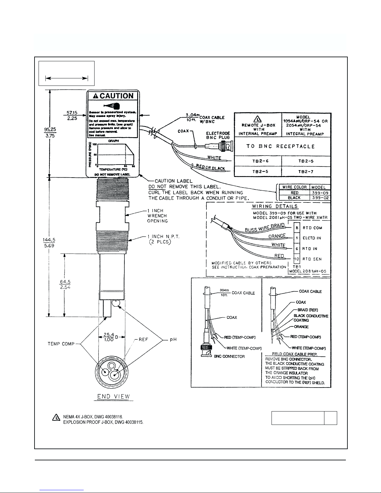
1.3.2 Integral Preamplifier Jumper. If direct input
from a sensor without a preamplifier is used, refer to
Figure 1-1 and Figure 1-2 for sensor wiring. The sen-
sor cannot be more than 15 (4.5m) feet from the transmitter for this option.
Many pH sensors without preamps come with BNC
connectors, but the Model 2081 pH only takes bare
wire connections. To make the sensor compatible, cut
off the BNC and terminate it according to Figure 1-2.
1.3.3 Power and Signal Wiring. The power and signal
wiring terminal is TB2 terminals 1 through 4 as shown
in Figure 1-1.
1.4 JUMPER SETTINGS.
1.4.1 General This section describes how to set the
jumpers on the CPU board for the following:
CAUTION
The circuit board is electrostatically sensitive. Be sure to observe handling precautions for static-sensitive components.
1. Output value in fault (alarm) mode
2. 50/60 Hz operation
3. Security
1.4.2 Fault Mode Output. The default output of the
transmitter during a fault condition is determined by
the position of the default current output jumper located on [JP3] (refer to Figur
e 1-3). The output can be set
to default either:
- below 4mA - JP3 with jumper
- above 20mA - JP3 without jumper (factory setting).
Place jumper on one post only to prevent misplacing
it. The following are possible faults. See Section 8.0
for
further information.
Fault Mnemonics
“SLP – FAIL” - Electrode slope out of limits
“ELEC – FAIL” - Transmitter electronics failure
“rngE – LOOP” - pH value outside 4-20 mA range
points
“tEnP – Lo” - Temperature too low or RTD shorted
“tEnP – Hi” - Temperature too high or RTD open
1.4.3 Fifty Hz Operation. See Figur
e 1-3. Although
the 2081 uses direct current, a jumper selection may
be made to help reduce electrical noise from the operating environment. North America uses 60 Hz ac
power, while Europe uses 50 Hz ac power.
– 50 Hz - JP1 with jumper
– 60 Hz - JP1 without jumper (factory setting).
Place jumper on one post only to prevent misplacing it.
1.4.4 Security. Also explained in Section 6.0
. See
Figur
e 1-3.
– Disable 2081 push buttons - JP4 without jumper.
Place jumper on one post only to prevent misplacing it.
– Enable 2081 push buttons - JP4 with jumper (fac-
tory setting).
MODEL 2081 pH SECTION 1.0
INSTALLATION
Page 7

3
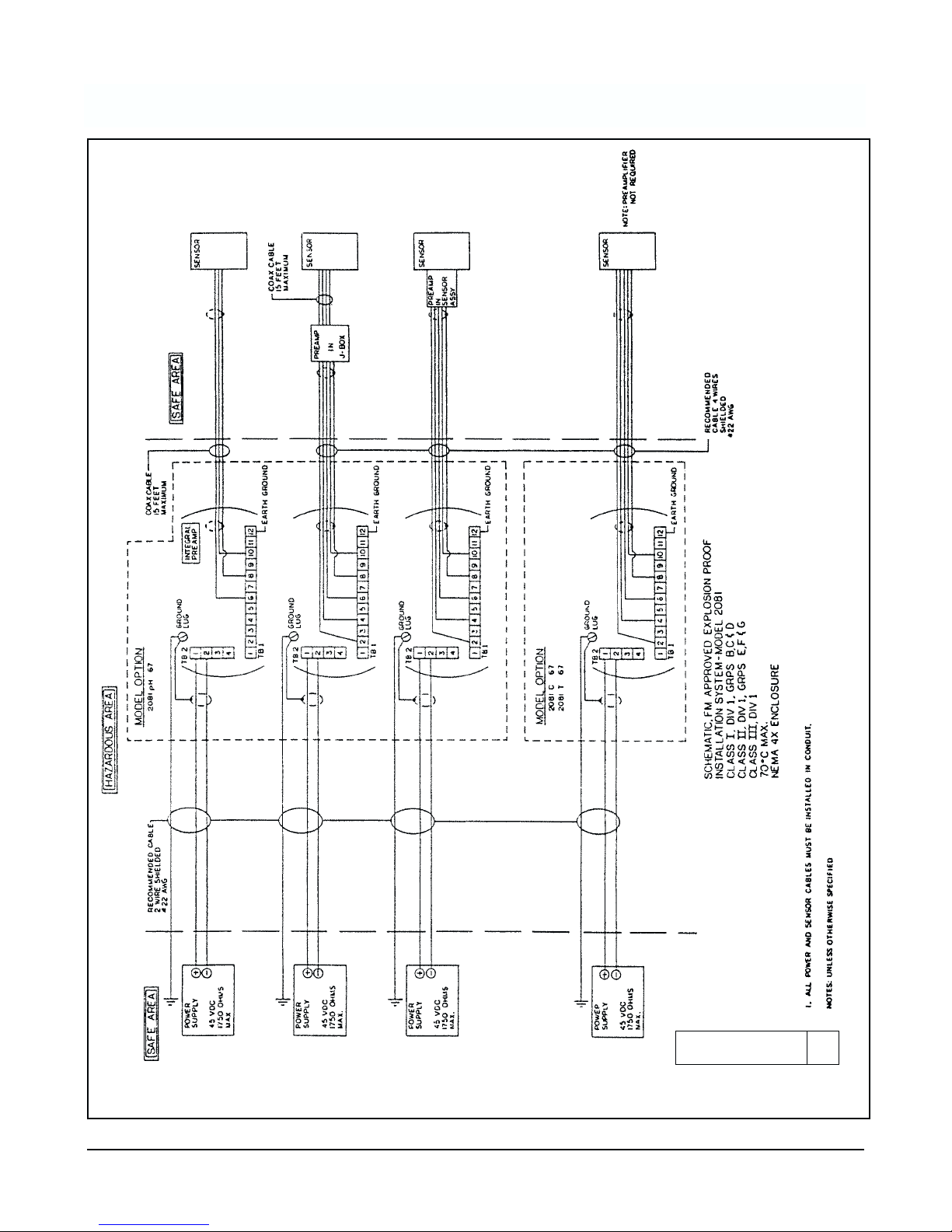
1.5 HAZARDOUS LOCATIONS-EXPLOSION PROOF
INSTALLATIONS. In order to maintain the explosion
proof rating for installed transmitter, the following conditions must be met.
1. The transmitter enclosure covers must be on hand
tight and the threads must not be damaged.
NOTE
These covers seat on rings which serve to
provide a dust proof enclosure for Class II
and Class III installations.
2. Explosion proof "Y" fittings must be properly
installed and plugged with a sealing compound to
prevent explosive gases from entering the transmitter. CSA has determined that the transmitter
housing is "Factory Sealed". Installation of "Y" fittings and the use of sealing compound is not
required for CSA approved Explosion Proof installations.
NOTE
Do not install sealing compound until all
field wiring is completed.
CAUTION
Sealing compound must be installed prior
to applying power to the transmitter.
3. If one of the conduit connections on the housing is
not used, it must be closed with a threaded metal
plug with at least five threads engaged.
4. The serial tag cover on the external ZERO and
SPAN adjustments must be in place.
6. Explosion proof installation must be in accordance
with Drawing Number 1400160 (see Figure 1-5).
5. For sensors in hazardous area locations, explosion
proof junction boxes can be provided to house the
preamplifier. This does not warrant the pH or ORP
sensor explosion-proof. Maximum safety can be
achieved by installing an intrinsically safe system
where Hazardous Area requirements must be met.
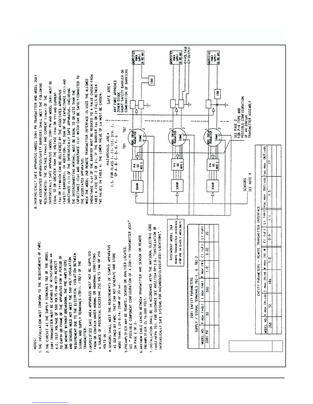
1.6 HAZARD LOCATIONS - INTRINSICALLY SAFE
INSTALLATIONS. See Figure 1-4. To secure and
maintain intrinsically safe installations for the appropriate approval agency, the following conditions must
be met:
1. Code 67 must be specified when ordering F.M.
(Factory Mutual) units. Approved “Entity”
installation must be in accordance with
Drawing Number 1400161 (see Figure 1-6 and
Figure 1-7).
2. Code 69 must be specified when ordering
C.S.A. (Canadian Standards Association) units.
Installation must be in accordance with Drawing
Number 1400162 (see Figure 1-8).
MODEL 2081 pH SECTION 1.0
INSTALLATION
Page 8
4
FIGURE 1-1. Model 2081 pH Power and Sensor Wiring (see also Figure 1-2 for sensor wiring)
WHEN INCH AND METRIC DIMS
ARE GIVEN
MILLIMETER
INCH
DWG. NO. REV.
40208101 B
MODEL 2081 pH SECTION 1.0
INSTALLATION
Page 9
5
FIGURE 1-2. Sensor Wiring Details For use with 2081 pH
WHEN INCH AND METRIC DIMS
ARE GIVEN
MILLIMETER
INCH
DWG. NO. REV.
40039903 G
MODEL 2081 pH SECTION 1.0
INSTALLATION
Page 10
6
DWG. NO. REV.
233050-00
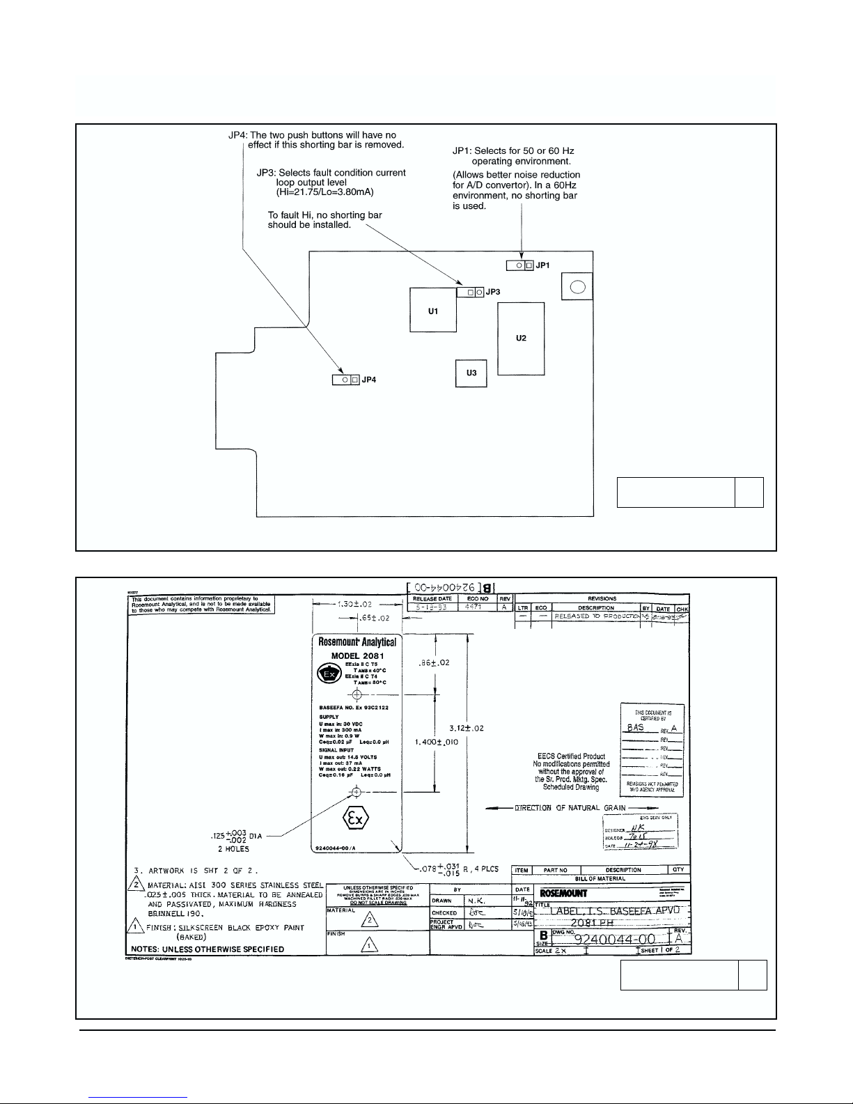
FIGURE 1-3. Model 2081 pH Jumper Settings
FIGURE 1-4. BASEEFA Label for Intrinsically Safe Installation
DWG. NO. REV.
9240044-00 A
MODEL 2081 pH SECTION 1.0
INSTALLATION
Page 11
7
FIGURE 1-5. Explosion Proof System Installation Schematic (FM)
DWG. NO. REV.
1400160 A
MODEL 2081 pH SECTION 1.0
INSTALLATION
Page 12
8
FIGURE 1-6. Intrinsically Safe System Installation Schematic (FM) Page 1 of 2
DWG. NO. REV.
1400161 A
MODEL 2081 pH SECTION 1.0
INSTALLATION
Page 13

9
FIGURE 1-7. Intrinsically Safe System Installation Schematic (FM) Page 2 of 2)
DWG. NO. REV.
1400161 A
MODEL 2081 pH SECTION 1.0
INSTALLATION
Page 14

10
FIGURE 1-8. Intrinsically Safe System Installation Schematic (CSA)
DWG. NO. REV.
1400162 A
MODEL 2081 pH SECTION 1.0
INSTALLATION
Page 15

11
FIGURE 2-1
Wiring Setup
SECTION 2.0 QUICK START-UP PROCEDURE
2.1 General. The 2081 pH is shipped from the factory
in a configuration that is acceptable in many applications. The instrument is set-up as follows:
• Measures from 0-14 pH
• 0 pH will correlate to a 4 mA current output
• 14 pH will correlate to a 20 mA output
• Temperature readings will be in degrees C
• Automatic temp. compensation will be on
• External preamplifier
If this described set-up is compatible with your application, you can utilize the following Quick Start-up
instructions, below, to expedite the commissioning
and calibration of your instrument. Otherwise, follow
the detailed instructions in Section 3.0
to set the
desired pH range, Section 4.0 to start-up, and
Section 5.0 to calibrate your instrument.
2.2 Set-up instrument.
Connect a power supply, current meter and an appropriate sensor to the 2081 Transmitter, as illustrated in
the figure below.
2.1.1 Connect loop power: -wire
power supply to the 2081 (TB2) adjust supply to approx. +24VDC
2.1.2 Connect current meter:
-wire meter to TEST connections to read
mA output (+ to +)
Model 2081 (short cover removed)
View of Interface PCB
* Install JP1 if internal preamplifier is
used. Remove if sensor or junction
box preamplifier is used.
2.1.3 Connect Sensor to 2081:
- wire sensor to TB1 as
illustrated below
2.1.4 Prep Sensor for calibration: (Refer to Sensor Manual)
Examples: - 381 Sensor must have a liquid junction and glass electrode installed
-399 Sensor requires removal of red boot cover, only
– *Black to TB1-1, instead of TB1-2, if unit has
JP1 in place.
12 11 10 9 8 7 6 5 4 3 2
4 3 2
TB2
TB1
SENSOR
mA
Power
Supply
– Loop
+ Loop
Black (mV-in)
Green (+5)
White (RTD IN)
Clear (RTD COM)
Red (RTD SEN)
TEST
+
+
+
MODEL 2081 pH SECTION 2.0
QUICK START-UP PROCEDURE
Page 16

FIGURE 2-2. Button Use.
12
2.3.3 Access the temperature adjustment feature of
the 2081 by pressing both push buttons at the same
time. Display will scroll through the menu selections.
2.3.4 When “tAdj” appears on the display, release
both buttons. Display will show the current temperature read by the RTD built into the sensor connected
to the transmitter.
1. If this reading matches your standardized
measuring device within your tolerances, go on
to Section 2.4
(Two-Point Calibration).
2. If this reading is not close enough to your standardized temperature measuring instrument,
refer to steps 1 through 4 in Section 5.2
Te mp erature Calibration, to set the temperature reading of the sensor to your standard temperature
measuring instruments value.
Both buttons in:
1. Scrolls through menu if held.
2. Enters new value into memory if only held
momentarily.
Number one in, to scroll through digit values.
Number two in, to select digit position.
2.3 Temperature Calibration. Since pH value is related
to the temperature of the process, the 2081 transmitter
temperature readings should be checked for matching
with your standardized temperature measuring sensor.
To do so:
2.3.1 Place your sensor connected to the 2081 transmitter in a beaker of process material. Place your standardized temperature measuring instrument (thermometer) into the same solution.
2.3.2 Allow a minimum of 10 to 15 minutes for the transmitters sensors to acclimate to the solutions temperature.
NOTE
The 2081 has two pushbuttons on its side for
manual operation. Keypress combinations
allow you to activate software menus to display and enter information. See Figur
e 2-2.
Push Buttons (side view)
OUT
IN
➡
➡
➡
2081 Display
02
0255..CC
5
IN
➡
2081 Display
025
025..CC
C
IN
1
2
1
2
MODEL 2081 pH SECTION 2.0
QUICK START-UP PROCEDURE
Page 17

13
2.4 Two-Point Calibration
Sensor should still be in the first buf
fer solution.
The sensor is placed in a buffer solution and the buffer value
is entered into the 2081. The sensor is placed in a different
buffer solution and that value is entered into the 2081. The
2081 will calculate the new slope from these values.
2.4.1 Compare the 2081 pH reading to the buffer value
that the sensor is in. If the display doesn't read the buffer
value, then enter the buffer value into the 2081, using the
following directions. If display reading is correct, skip to
Section 2.4.3, step 5.
2.4.2 Access the “buF1” feature on the 2081:
1. Press both push buttons in; display will scroll through
menu selections
2. When display reads “buF1”; release the buttons; display reads last buffer value entered. Far right digit will
be flashing, indicating that you may enter data.
2.4.3 Enter the buffer pH value that the sensor is in:
1. Press button #2 to select digit position to modify.
Selected digit will be flashing. Holding the button in
will cause selected position to shift to the left, then
back around again.
2. Release button when the desired digit is flashing.
3. Press button #1 to change digit's value. Holding the
button in will cause the selected digit to increase in
value, then back around again.
4. Release the button when the desired digit value is displayed.
5. Press both buttons in, briefly, to enter the new value into
memory. The 2081 will default to the pH reading. The
2081's pH reading will not change until the “buF2” value
is entered into memory. at the end of Section 2.4.5.
To 2081
pH Sensor
Buffer #1
(i.e., 4 pH)
Push Buttons
(side-view)
2081 Display
buF1
buF1
2081 Display
Scrolling
OUT
IN
➡
➡
➛
>
>
➡
2081 Display
00..00
00
2081 Display
11..00
00
1
0
IN
>
>
2081 Display
44..00
00
2081 Display
33..95
95
4
>
2081 Display
33..95
95
=
Buffer #1
4.00 pH ?
>
>
➡
2081 Display
00
00..00
2081 Display
00..000
0
0
2081 Display
00..000
0
0
0
IN
>
>
1
2
1
2
MODEL 2081 pH SECTION 2.0
QUICK START-UP PROCEDURE
Page 18

14
2.4.3 2-Point Calibration (cont.)
Remove the sensor from buffer #1. Rinse Sensor in water
(Deionized), then place in the 2nd buffer solution. The sensor is placed in the second buffer solution and that buffer
value is entered into the 2081. The 2081 will calculate the
new slope from the two buffer values.
2.4.4 Compare the 2081 pH reading to the buffer value
that the sensor is in. If the display doesn’t read the buffer
value, then enter the buffer value into the 2081, by performing Sections 2.4.2 - 2.4.3
; substituting the buffer #2
value for the buffer # I value.
If display reading is correct, go to Section 2.4.3, step 5..
2.4.5 After the buffer value #2 value is entered into the
2081, it calculates the sensor’s slope. The transmitter and
sensor are now calibrated. Upon installation into the
process, a Standardization should be performed to
improve the reading accuracy (refer to Section 5.4
after
completing the Quick Start-up procedure).
Leave the sensor in buf
fer #2.
2.5 Current Output Check
Check the current output of the transmitter; sensor should
still be in buffer #2 (i.e., 10 pH).
2.5.1 Calculate the proper current output for the buffer
being used, with the adjacent formula.
Example: Sensor is acclimated in 10 pH buffer.
Transmitter is factory configured for 0-14 pH full-scale
range, and 4-20 mA output.
Current output should read 15.43 mA.
2.5.2 Remove the sensor from buffer #2. Rinse Sensor in
water(Deionized), then place in the 1st buffer solution.
Check the current output with the sensor acclimated to
buffer #1.
2.5.3 Calculate the proper current output for the buffer
being used, with the mA output formula.
Example: Sensor is acclimated in 4 pH buffer.
Transmitter is factory configured for 0-14 pH full-scale
range, and 4-20 mA output. Current output should read
8.57 mA.
NOTE
If the pH buffer readings are accurate and the
current output values are within tolerance, then
the unit is calibrated and ready to be placed
into service.
2081 Display
10
10..
05
05
=
Buffer #2
10.00 pH ?
+ Buffer Value #2
+ Buffer Value #1
mV reading
pH Value
2081 calculates the
sensor slope
(ideal is 59.1 mV/pH)
mA Buffer Value
=
(
––––––––––––––––
) X 16 + 4
output Full-scale Range
mA 10.00 pH
=
(
––––––––––––––––
) X 16 + 4
output 14
= 15.43 mA ± .16
mA Buffer Value
=(––––––––––––––––
) X 16 + 4
output Full-scale Range
mA 4.00 pH
=(––––––––––––––––
) X 16 + 4
output 14
= 8.57 mA ± .16
MODEL 2081 pH SECTION 2.0
QUICK START-UP PROCEDURE
pH Sensor
Buffer #2
(i.e., 10 pH)
Water (DI)
Rinse Sensor
➛
Page 19

15
3.1 GENERAL. Nearly all functions of the transmitter
are accessed through the dual push buttons. The
transmitter uses no potentiometers.
3.2 MENU SELECTION. The dual push buttons are
located on the side of the transmitter. Press and hold
both buttons to display the transmitter menu items.
See Figur
e 3-1. The display will show each item for
about one second then scroll to the next item. It will
continue to loop through the items until one is selected. To select an item, release both push buttons when
the desired item is displayed.
NOTE
When no push button is pressed for a period
of 60 seconds, the transmitter defaults to
reading pH. If the push buttons are accidentally released (e.g. buF2) and this would upset
the process, escape by waiting 60 seconds
for the transmitter to default to the pH reading.
3.2.1 Display Submenu. Functionality of the display
submenu (dISP) is the same as the main menu. To enter
the main menu, release both buttons on “dISP” and the
display will read “PH”. To read the pH value in the sub-
menu when “PH” is displayed, press and quickly
release both push buttons. To escape from the submenu, simply depress both buttons and hold to enter
the main menu or wait 60 seconds for a pH reading.
3.2.2 Display Flags and Hold Mode. The transmitter
will activate a flag on the LCD corresponding to the
labeled units when appropriate. When the transmitter
is in hold output mode a flashing flag will appear on
the middle right hand side of the display and “HoId”
will flash periodically. The output will remain at the last
process value. To remove the hold mode, scroll to
“HoId” again and release both buttons.
3.3 VALUE ADJUSTMENT. Selection of a menu item
that has a user-adjustable value will cause a numeric
display with the right-most digit flashing. Depressing
and holding push button #1 will cause the number
flashing to increment upwards, looping back to zero.
Depressing and holding push button #2 will shift the
flashing cursor to the next decade, looping back to the
right most decade. Once the number is correctly
entered, depressing both buttons briefly will enter the
displayed value into memory. The transmitter will
return to reading pH.
SECTION 3.0 DESCRIPTION OF CONTROLS
MAIN DISPLAY
MENU SUBMENU
dISP – – – – – – – – – – – – – – – – – – – – – – –
→
PH pH value
Std Standardize pH inPt mV input
Ho Id Initiate and remove hold output mode curr Output in mA
buF1 Buffer #1 DIo Output in % of full scale
buF2 Buffer #2 DC Temperature, °C
SLP Electrode slope (mV/pH unit) DF Temperature, °F
LoPH 4 mA range point
HiPH 20 mA range point
tAdJ Standardize temperature, °C
• Press and hold both buttons auto scrolls through main menu
and submenu.
• Release buttons to select item.
• Push button #1: Press and hold auto scrolls digits.
• Push button #2: Press and hold auto shifts decades.
• Enter a value: Depress both buttons briefly.
FIGURE 3-1. Menu Description
MODEL 2081 pH SECTION 3.0
DESCRIPTION OF CONTROLS
Page 20

SECTION 4.0 RANGE CONFIGURATION
4.1 RANGE CONFIGURATION. Corresponding pH
values for output zero (4 mA) and full scale (20 mA)
are user selectable. The factory values are 4 mA = 0
pH and 20 mA = 14 pH.
A. Output Zero (4 mA) “LoPH”
1. Depress and hold both push buttons. The display
will begin to auto scroll.
2. Release both keys when “LoPH” is displayed. The
present 4 mA pH value in memory will be displayed with the last digit flashing.
3. Depress and hold push button #1 (scroll) and #2
(shift) as needed to display the desired pH value.
4. Enter the value into memory by depressing both
push buttons briefly. The display will return to displaying the present pH value.
B. Full Scale (20 mA) “HiPH”
1. Depress and hold both push buttons. The display will begin to auto scroll.
2. Release both keys when “HiPH” is displayed. The
present 20 mA pH value in memory will be displayed with the last digit flashing.
3. Depress and hold push button #1 (scroll) and #2
(shift) as needed to display the desired pH value.
4. Enter the value into memory by depressing both
push buttons briefly. The display will return to displaying the present pH value.
NOTE
For a reverse output, enter the higher value
for “LoPH”, and the lower value for “HiPH”.
NOTE
If the factory values are to be used, the
Quick Start-up Procedure may be used.
See Section 2.0
.
MODEL 2081 pH SECTION 4.0
RANGE CONFIGURATION
16
Page 21

17
SECTION 5.0 START-UP AND CALIBRATION
5.1 GENERAL. The sensor must be wired to the
transmitter for calibration. See the appropriate sensor manual for additional instructions relating specifically to the sensor.
5.2 TEMPERATURE CALIBRATION. For the most
accurate temperature compensation, the temperature reading may need adjusting. The following
steps should be performed with the sensor in a grab
sample or process of known temperature. Calibrate
at or near the process temperature for greatest
accuracy.
1. Depress and hold both push buttons simultaneously to enter the transmitter menu. The transmitter will auto scroll through the menu items.
2. When the display shows “tAdJ”, release both buttons. The display will show the present temperature value in degrees Celsius with the last digit
flashing. The tenths digit will alternate between a
value and °C. (The temperature can only be standardized in °F by using the Model 275 for configuration).
3. Compare the displayed reading with a calibrated temperature reading device. If the reading
requires adjustment, proceed to step 4. Otherwise, depress both push buttons briefly to
accept the displayed value.
4. Depress and hold push buttons #1 (scroll) and
#2 (shift) as needed to display the desired temperature value.
5. Enter the correct value into memory by depressing both push buttons briefly. The display will
return to displaying the present pH value.
5.3 BUFFER CALIBRATION. The two buffer calibra-
tion will calculate the slope (efficiency) of the pH
sensor. (Computed limits: 47.3 to 59.9 mV/pH).
1. Obtain two pH buffer solutions with values at
least two pH units apart. Unopened buffers have
a shelf life of about a year, and once opened,
should ideally not be reused because of possible contamination.
2. Depress and hold both push buttons to scroll
through the menu items to “HoId”, then release
both buttons to place the transmitter in hold status (“HoId” will periodically flash). This will maintain the output at the last process value read by
the transmitter and activate the hold flag on the
middle right hand side of the display.
3. Remove the sensor from the process and clean
it if necessary. Shake the sensor down to
remove entrapped air bubbles from the measurement tip.
4. Place the sensing portion of the pH sensor into
a beaker containing the first buffer solution.
5. Allow the pH reading to stabilize, note the sensor temperature from the display submenu, then
note the value at the buffer at that temperature.
Buffer pH values of various temperatures are
located on most buffer bottles. For example, at
5°C (41°F) a typical buffer is 6.95 pH but at 25°C
(77°F) it is 6.86 pH. See “Note on Buf
fers” on the
following page.
6. Depress and hold both push buttons to scroll
through the menu items to “buF1” then release
both push buttons. The display will show the pH
value currently in “buF1” memory.
7. Depress and hold push button #1 (scroll) then
#2 (shift) as needed to display the buffer1 pH
value.
8. Enter the buffer value (at the sensor temperature) into memory by depressing both push buttons briefly. The transmitter will memorize this
value but will not change the calibration until
buffer #2 is entered. The display will return to
reading the present pH value.
9. Remove the sensor from the buffer, rinse and
gently dry it.
10. Place the sensing portion of the pH sensor into
a beaker containing the second buffer solution.
11. Follow the instructions in steps 5 through 8 for
buffer 2 (“buF2”). After entering the “buF2” value
the transmitter will calculate the electrode slope
and standardize the reading.
MODEL 2081 pH SECTION 5.0
START-UP AND CALIBRATION
Page 22

18
12. Return the sensor to the process.
13. Depress and hold both push buttons to scroll
through the menu items to “HoId”, then release
both push buttons to remove the transmitter
from hold status. The hold flag will disappear
and the display will stop flashing “Ho Id”.
NOTE
To observe the calculated slope value, follow
the instructions in Section 5.5
.
NOTE ON BUFFERS
The pH of buffer solutions changes with
temperature. This is very important to know
if you are calibrating in a very hot or cold
environment and you need good accuracy.
Rosemount Analytical recommends use of
the following NIST (National Institute of
Standards and Technology - formerly NBS)
buffers:
5.4 pH STANDARDIZATION.
After a buffer calibration, the system should be standardized on line by taking a grab sample. Standardization will not calculate the electrode slope, but will
improve system accuracy.
1. Take a grab sample which is as close to the
sensor as possible. Note the transmitter pH
reading at this time.
2. Using a calibrated pH instrument, determine
the pH of the process or grab sample. The
reading must be temperature compensated to
25°C (77°F) if the sample is not at 25°C. Note
this value.
3. Calculate the difference by subtracting the pH
value noted in Step 1 from the pH value found
in step 2.
4. Depress and hold both push buttons to scroll
through the menu items to “Std”, then release
both push buttons. The display will show the
present pH value with the last digit flashing.
5. Correct the pH standardize value for time lag by
adding the difference calculated in step 3 to the
amount displayed on the transmitter.
Example: If pH in step 1 is 2.3 and pH in step
2 is 2.8, the difference noted in step 3 would be
+.5 pH. The present transmitter pH value would
be increased by .5 pH.
6. Depress and hold push button #1 (scroll) and
#2 (shift) as needed to display the pH value calculated in step 5.
7. Enter the value into memory by depressing both
push buttons briefly. The transmitter will return
to displaying the present pH value.
5.5 pH GLASS SLOPE.
The slope (efficiency) of the pH glass electrode can
be entered directly if known (slope limits: 47.3 to
59.9 mV/pH). As the electrode ages the slope will
decrease.
1. Depress and hold both push buttons to scroll
through the menu items to “SLP”, then release
both buttons. The display will show the present
slope with the last digit flashing.
2. Depress and hold push button #1 (scroll) and
#2 (shift) as needed to manually enter a slope
value, if desired.
3. Enter the value into memory by depressing both
push buttons briefly. The transmitter will return
to displaying the present pH value.
°C °F pH pH pH
5 41 4.00 6.95 9.39
10 50 4.00 6.92 9.33
15 59 4.00 6.90 9.28
20 68 4.00 6.88 9.22
25 77 4.01 6.86 9.18
30 86 4.01 6.85 9.14
35 95 4.02 6.84 9.10
40 104 4.03 6.84 9.07
45 113 4.04 6.83 9.04
50 122 4.06 6.83 9.01
MODEL 2081 pH SECTION 5.0
START-UP AND CALIBRATION
Page 23

19
MODEL 2081 pH SECTION 5.0
START-UP AND CALIBRATION
5.6 HOLD MODE FOR MAINTENANCE.
Before performing maintenance of the sensor, or
buffer checks, the transmitter should be placed in
the "Hold" mode. This mode of operation maintains
the output current at the last process value. To initiate "hold " mode:
1. Depress and hold both push buttons simultaneously until "Hold" is displayed on the screen.
2. Release both buttons.
a The "Hold" flag will flash, and
b. The display will show "Hold" every two sec-
onds to confirm the hold status.
To place the transmitter back into normal operation,
(remove from "Hold" mode)
1. Depress and hold both push buttons simultaneously until "Hold" is displayed on the screen.
2. Release both buttons.
a. The "Hold" flag will stop flashing.
b. The display will stop showing "Hold" every
two seconds.
c. The transmitter output current will return to
normal operation.
5.7 SENSOR MAINTENANCE.
Always calibrate after cleaning or repair of the pH
sensor.
Always place transmitter into the "Hold " mode of
operation while preforming any maintenance to the
sensor to avoid loss of process control.
Always return transmitter to normal operation after
installing the sensor back into the process.
NOTE
To clean the electrode, rinse with distilled
water or dilute acid/base, then gently dry
with a clean tissue. The electrode should
not be rubbed or abraded because this
increases the electrostatic forces and
thus the response time of the electrode,
and it also rapidly ages the delicate electrode gel layer. If possible, the stirring or
flow velocity past the electrode should
be increased rather than rubbing or
brushing the electrode.
Also, see the appropriate sensor manual
for any additional instructions.
Page 24

20
SECTION 6.0 KEYBOARD SECURITY
GENERAL. This feature allows the user to disable the
dual push buttons on the transmitter, preventing accidental or unauthorized changes to the calibration and
configuration via the transmitter. HART communication
is not effected by this change. Perform the following
steps to disable the push buttons:
CAUTION
The circuit board is electrostatically sensitive. Be sure to observe handling precautions for static-sensitive components.
1. Remove the display side cover.
2. On the CPU board (Figur
e 6-1, Model 2081 pH
jumper settings), move JP4 to one post only.
NOTE
For easy access, the electronics assembly
may be removed by pulling the assembly
straight out.
3. Replace the display side cover.
CAUTION
A minimum of seven cover threads must
be engaged in order for the transmitter to
meet explosion-proof requirements.
Replace the jumper to enable push button operation.
FIGURE 6-1. Model 2081 pH Jumper Settings
JP3
JP4
JP1
JP1: Selects for 50 or 60 Hz operating environment.
(Allows better noise reduction for A/D convertor). In a
60Hz environment, no shorting bar is used.
JP4: The two push buttons will have no
effect if this shorting bar is removed.
JP3: Selects fault condition current loop
output level (Hi=21.75/Lo=3.80mA)
To fault Hi, no shorting
bar should be installed.
U2
U3
U1
DWG. NO. REV.
233050-00
MODEL 2081 pH SECTION 6.0
KEYBOARD SECURITY
Page 25

21
SECTION 7.0 THEORY OF OPERATION
GENERAL This section is a general description of how the transmitter operates. This section is for those users
who desire a greater understanding of the transmitter’s operation.
The measurement of the process’ pH is accomplished by the use of two electrodes within the sensor. The glass
electrode is pH sensitive and generates a high impedance millivolt potential directly proportional to the process
pH. The reference electrode is a second half cell that completes the circuit via a liquid junction. The high impedance signal is preamplified at or near the sensor to allow a stable noise-free signal that can be transmitted up to
1000 feet.
The transmitter also measures the process temperature via a platinum 100 ohm RTD imbedded in the sensor.
Advanced circuitry is used to eliminate errors due to changes in cable resistance. The transmitter uses this temperature measurement to compensate for the changes in the sensor’s millivolt output caused by process temperature change.
MODEL 2081 pH SECTION 7.0
THEORY OF OPERATION
Page 26

22
SECTION 8.0 DIAGNOSTICS AND TROUBLESHOOTING
TABLE 8-2. RTD Resistance Values
TABLE 8-1. Diagnostic Messages
Temperature Resistance
0°C 100.00 ohms
10°C 103.90 ohms
20°C 107.79 ohms
30°C 111.67 ohms
40°C 115.54 ohms
50°C 119.40 ohms
60°C 123.24 ohms
70°C 127.07 ohms
80°C 130.89 ohms
90°C 134.70 ohms
100°C 138.50 ohms
Display Description Corrective Action
“SLP – FAIL” Electrode slope out of limits See Table 8-5
“FAIL” Transmitter electronics failure See Table 8-5
“rngE – LOOP” pH value outside 4-20 mA range points Return pH to within range, replace sensor
“SnSr – FAIL” Sensor failure or A-D failure See Table 8-5
“tEnP – Lo” Temperature too low or RTD shorted Check wiring, calibrate temperature, bring sensor within
“tEnP – Hi” Temperature too high or RTD open temperature specifications, replace stack, replace sensor.
Note: If in manual temp. mode, RTD or appropriate resistor
must
be in place. See Table 8-2.
MODEL 2081 pH SECTION 8.0
DIAGNOSTICS AND TROUBLESHOOTING
8.1 DIAGNOSTICS. The transmitter has a diagnostic
feature which continuously monitors for fault conditions that would cause an error in the measured pH
value. A fault condition is reported to the current loop
as jumper selected. If jumper JP3 in in place, the output will be driven below 4 mA. If the jumper is not in
place, the output will be driven above 20 mA. See
Figure 1-3 for jumper location. The display will alter-
nate between the pH value and the appropriate fault
mnemonic (Table 8-1). The fault sequence will contin-
ue until the cause of the fault has been corrected.
8.1.1 Diagnostic Messages. Table 8-1 lists the fault dis-
play, discribes the meaning of each and appropriate
corrective action. All of these faults are detected
online, except for the slope error which can occur during an off-line buffer calibration.
8.1.2 Temperature Compensation. Table 8-2 is a refer-
ence of RTD resistance values at various temperatures.
These are used for test and evaluation of the sensor.
NOTE
Ohmic values are read across the RTD element and are based on the manufacturer’s
stated values (±1%). Allow enough time for the
RTD element to stabilize to the surrounding
temperature.
8.2 TROUBLESHOOTING. The Model 2081 pH transmitter is designed with state-of-the-art surface mount
technology and microprocessor technology, making
troubleshooting simple and direct. Subassembly
replacement, i.e. PCB stack replacement, is all that is
required.
NOTE
Transmitters should not be left in service once
they have been determined to be inoperable.
8.2.1 General. If failure does occur, complete the following steps:
1. Check for a fault flag. If a fault condition exists, refer
to Table 8-1 for the fault mnemonic explanation.
2. Check wiring connections for proper installation.
3. Refer to Troubleshooting Table 8-5. The table is
arranged with the most common problems listed
first.
Page 27

23
8.2.2 Bench Check. Sensor simulation may be used
to check the operation of the Model 2081. If the Model
2081 is using the integral preamplifier, connect the
simulator(s) according to Figur
e 8-1. If the model 2081
has no preamplifier, connect the simulator(s) as shown
in Figure 8-2. Refer to Table 8-2 for the appropriate
RTD resistance.
CAUTION
Do not use over 55 volts to check the loop, or
damage to the transmitter electronics may
result.
1. After completing power and simulator(s) wiring,
apply 24Vdc power to the Model 2081.
2. Simulate 25°C to the transmitter by placing 110
resistance between TB6 and TB8. The Model 2081
should display ~25°C (refer to Section 3.2.1).
Adjust the temperature display if necessary (Refer
to Section 5.2).
3. Simulate 4 pH by applying +177 millivolts dc
(W/integral preamplifier) or +1.52 VOLTS DC (W/O
preamplifier).
NOTE
Using mV inputs for units without preamps will
result in a “SnSr FAIL” fault code.
4. Depress and hold both push buttons to scroll
through the menu items to “buF1” then release
both buttons. The display will show the pH value
currently in “buF1” memory.
5. Depress and hold push button #1 (scroll) then #2
(shift) as needed to display 4.00.
6. ENTER the value into memory by simultaneously
depressing both push buttons briefly.
7. Simulate 10 pH by applying -177 millivolts dc
(
W
/preamplifier) or 1.173 VOLTS DC (W/O pream-
plifier).
8. Follow steps 4-6 for “buF2”, entering 10.0pH.
9. The Model 2081 should display ~ 10.00.
10. If the transmitter performs properly, then the sen-
sor should be checked.
If the integral preamplifier is suspect, bypass it and
follow the instructions for calibration without the preamplifier.
8.2.3 Sensor Troubleshooting. In addition to the fault
mnemonics that relate to a possible sensor problem
(Table 8-1 and Table 8-5), the transmitter can display
the input in millivolts generated from the sensor. See
Table 8-3 for how the millivolt input relates to pH. If the
transmitter values are not within about 20% of those in
Table 8-3, the transmitter has been incorrectly stan-
dardized for pH, the reference may be significantly
poisoned, or some other significant problem exists. To
read the millivolt input, go to “inPt” in the display submenu.
*99% pH electrode efficiency
8.2.4 PCB Stack Replacement. If it becomes necessary to replace the PCB stack (both CPU and Sensor
boards) there is no need to field calibrate electronics
upon replacement, since the millivolt input and output
digital trim is performed at the factory. Simply remove
the old assembly, reconnect the new stack, and perform the sensor calibration.
8.2.5 LCD Display Replacement. If the display board
needs to be replaced you will need both the generic
display assembly P/N 23419-00 and the pH overlay
P/N 9240008-00.
CAUTION
Remove power from transmitter before
removing the electronics cover.
pH Input to Transmitter in MILLIVOLTS
15°C
(59°F)
25°C
(77°F)
50°C
(122°F)
80°C
(176°F)
0 396 410 444 486
1 340 351 381 416
2 283 293 317 347
3 226 234 254 277
4 170 176 190 208
5 113.2 117.1 127.0 138.7
6 56.6 58.6 63.5 69.4
70000
8 –56.6 –58.6 –63.5 –69.4
9 –113.2 –117.1 –127.0 –138.7
10 –170 –176 –190 –208
11 –226 –234 –254 –277
12 –283 –293 –317 –347
13 –340 –351 –381 –416
14 –396 –410 –444 –486
TABLE 8-3. Sensor Input* to Transmitter Verses
pH at Four Temperatures
15°C
(RTD = 105.85 )
25°C
(RTD = 109.74 )
80°C
(RTD = 130.89 )
pH Vdc input Vdc input Vdc input
0 1.75 1.76 1.84
1 1.69 1.71 1.77
2 1.63 1.65 1.70
3 1.58 1.59 1.63
4 1.52 1.53 1.56
5 1.47 1.47 1.49
6 1.41 1.41 1.42
7 1.35 1.35 1.35
8 1.29 1.29 1.28
9 1.24 1.23 1.21
10 1.18 1.17 1.14
11 1.12 1.11 1.07
13 1.01 1.00 0.93
14 0.95 0.94 0.86
TABLE 8-4
VOLTAGE Input to Transmitter (no integral preamplifier)
MODEL 2081 pH SECTION 8.0
DIAGNOSTICS AND TROUBLESHOOTING
Page 28

24
SYMPTOM PROBLEM ACTION
Change in pH slope (value 1. Old or coated glass electrode. 1. Clean or replace glass electrode.
decreasing to 49.0 or less). 2. Bad RTD value. 2.
See Table 8-2 with RTD resistance
and temperature values.
pH value locks up (no change 1. Glass electrode cracked. 1. Replace glass electrode.
of reading in different buffers). (if value stays at 6.5-7.0 pH) 2. Clean glass electrode.
2. Coated glass electrode.
2081 pH value not the same 1. Grab sample incorrect. 1. Re-evaluate sample technique
as grab sample of process. and equipment.
2. Unclear what is correct. 2. Test with buffer solution.
3. 2081 pH out of calibration. 3. Recalibrate per start-up and
calibration section.
Fault code “tEnP-Lo” or 1. Miswire. 1. Check wiring between the sensor
“tEnP-H i”. and the transmitter.
2. Open or shorted RTD. 2. Replace RTD or sensor.
3. Manual temperature mode. 3. Appropriate resistor must be
in place TB1-6 & 8. See Table 8-2.
Fault code “SLP-FAIL”. 1. Coated electrode. 1. Clean or replace electrode.
2. Improper buffer calibration. 2. Recheck buffer accuracies.
Change slope value (SLP) to 59.1
3. Defective electrode. 3. Replace electrode.
4. Plugged liquid junction. 4. Replace liquid junction.
Fault code “rngE-LOOP”. 1. Process value is outside. 1. Return process to normal.
4-20 mA range points. Check grab sample.
Fault code “FAIL”. 1. Input signals are invalid. 1. Toggle Power
2. Calculation is invalid. 2. Change slope value (SLP) to 59.1
3. Defective PCB stack. 3. Perform a complete bench check
to try to clear the error.
No output current. 1. Defective PCB stack. 1. Replace PCB stack.
2. Miswire. 2. Check for short.
Low output current. 1. Circuit loading with excessive 1. Consult output loading limits
resistance on output .
2081 pH specifications (1840 ohms
max load).
“inPt” in display submenu reads 1. Junction poisoning. 1. Replace junction or sensor.
increasingly greater or less than
0 mV at 7.00 pH.
Fault code “LOOP” flashing 1. Model 268 or other host has 1. Model 268 or other host can
intermittently with pH and set the output to a specific value. return transmitter to normal
output value. operation.
Fault code “SnSr - FAIL 1. mV input exceeds ±675mV or 1. Check wiring; toggle power.
RTD resistance is over 600 . 2. Perform a complete bench check.
2. A-D failure 3. Replace PCB stack.
TABLE 8-5. Troubleshooting Guide
MODEL 2081 pH SECTION 8.0
DIAGNOSTICS AND TROUBLESHOOTING
Page 29

25
FIGURE 8-1
Bench Check (With Preamplifier)
FIGURE 8-2
Bench Check (Without Preamplifier)
12 11 10 9 8 7 6 5 4 3 2 1
4 3 2 1
TB2
Pin connection on
10 to check thru
the Preamp
mA
Power
Supply
RTD Decade
Box or Resistor
– Loop
+ Loop
TEST
+
COMM
+
Millivolt Source
+
+
Jmpr
12 11 10 9 8 7 6 5 4 3 2 1
4 3 2 1
TB2
Pin connection
on 11 to bypass
the Preamp
Pin connection
on 2 to check without
Preamp
mA
Power
Supply
RTD Decade
Box or Resistor
– Loop
+ Loop
TEST
+
COMM
+
Voltage Source
+
+
Jmpr
■■
■■
* JP1 installed.
NOTE: Using millivolts for this test will result
in a “SnSr-FAIL” fault code. See Table 8-4 for
valid voltage inputs.
■■
■■
* JP1 is removed.
MODEL 2081 pH SECTION 8.0
DIAGNOSTICS AND TROUBLESHOOTING
Page 30

26
SECTION 9.0 DESCRIPTION AND SPECIFICATIONS
•
FIELD MOUNTED TRANSMITTER ideal for central data processing and control.
• MEMBER OF THE ROSEMOUNT SMART FAMILY
®
• LOCAL, PUSH-BUTTON INTERFACE for convenient calibration and range adjustment.
• HAZARDOUS AREA INSTALLATION certified NEMA 7B explosion-proof.
• NEMA 4X (IP65) WEATHERPROOF, CORROSION-RESISTANT ENCLOSURE.
• CONTINUOUS DIAGNOSTICS drive the output to a jumper-selectable high or low value in
the event of a failure.
9.1 FEATURES.
The Model 2081 pH Smart Transmitter, with the
appropriate sensor, is designed to continuously
measure pH in industrial and municipal processes.
This two-wire transmitter is a member of the
Rosemount SMART FAMILY of instruments, which
are designed to communicate with the hand-held
Model 275 SMART FAMILY Interface and any other
hosts that support the HART communications protocol. The Model 2081 design permits remote configuration, interrogation, testing, and diagnostics.
The Model 2081 pH features an easy-to-use, dual
push-button interface on the transmitter housing for
local calibration and range adjustment. The standard
LCD display menu indicates the pH value as well as
temperature, current output value, range values,
electrode slope, and fault messages. All functions
are microprocessor based, using no switches or
potentiometers.
The isolated 4-20 mA output is continuously
expandable over the measurement range, and may
be displayed in either milliamps or percent of full
scale. A hold output function is available for manual
control during routine sensor maintenance. While in
hold mode the current output signal will remain constant at the last current value.
In the event of a failure, the transmitter diagnostic
routine will drive the output below 4 mA or above 20
mA in addition to displaying a fault code on the transmitter.
With a two-point buffer calibration, the transmitter
automatically calculates the electrode slope and
memorizes the buffer values. On-line standardization is easily accomplished by simply entering the
pH value of a grab sample into the transmitter. The
transmitter uses an RTD signal from the sensor to
automatically compensate the pH reading for process
temperature fluctuations.
The Model 2081 pH transmitter is designed to be
weatherproof and corrosion resistant to meet NEMA
4X (IP65) standards. An optional pipe or wall mounting bracket is available. The transmitter is certified
NEMA 7B explosion-proof by Factory Mutual.
The Rosemount logo, HART and SMART Family are registered trademarks of
Rosemount Inc.
MODEL 2081 pH SECTION 9.0
DESCRIPTION AND SPECIFICATIONS
Page 31

27
MODEL 2081 pH SECTION 9.0
DESCRIPTION AND SPECIFICATIONS
9.3 PERFORMANCE SPECIFICATIONS
(Transmitter only)
Range: 0 to 14 pH
Output Scale: Zero Suppression: Up to 13 pH units
Span: From 1 to 14 pH units
Accuracy: ± 0.02 pH, 0.1°C
Resolution: 0.01 pH, 0.1°C
Repeatability: ± 0.01 pH
Stability: 1%/ year at 25°C
Temperature Effect: 0.02% F.S./°C
Vibration Effect: ± 1.0% of F.S. per SAMA PMC
31.1, Section 5.3, Condition 2.
EMI/RFI:
EN50081-1
EN50082-2
9.4 PHYSICAL SPECIFICATIONS
Electrical Connections: 1/2 in. NPT.
Model 275 SMART FAMILY Interface
connections permanently fixed to terminal block.
The terminal block also has removable
connectors for bare wire sensor connections.
Housing: Epoxy-polyester painted over low-copper
aluminum. BUNA-N O-rings on cover.
Recommended Cable: Transmitter to power supply
two-wire, 18 AWG, shielded, Belden 8760 or
equal (Rosemount Analytical PN 9200001).
Weight/Shipping Weight: 2.18 kg/2.68 kg (4.8 lb/5.9 lb)
9.2 FUNCTIONAL SPECIFICATIONS
Inputs: mV (for pH); resistance (for temperature)
Output: Two-wire 4-20 mA with superimposed HART
digital signal.
Power Supply and Load Requirements: See graph
below. A minimum loop resistance (load) of 250
ohms and minimum power supply voltage of 18
volts DC is required for digital communication.
Local Indication: Four digit LCD
Ambient Temperature: –30 to 70°C (–22 to 158°F)
Failure Mode Alarm: The analog signal will be driven
either below 4 mA or above 20 mA (userselectable) to alert the user.
Transmitter Security: Security activation (by internal
jumper) prevents changes to the transmitter
configuration from the local interface.
Relative Humidity : 0-95%
Automatic Temperature Compensation: Pt100 RTD
–15 to 115°C (5 to 239°F)
Enclosure: NEMA 4X (IP65) , weatherproof and
corrosion-resistant NEMA 7B, explosion proof
Hazardous Area Classification:
Explosion Proof:
FM: Class I, Div. 1, Groups B, C & D
Class II, Div. 1, Groups E, F, & G
Class III, Div. 1
CSA: Class I, Div. 1, Groups C& D
Class I, Div. 2, Groups A, B, C & D
Class II, Div. 2, Groups E, F & G
Class III, Div. 1
Intrinsic Safety:
FM: Class I, II & III, Div. 1
T4 T AMB= 40°C; T3AT AMB= 70°C
CSA: Class I, Div. 1
T 3C T AMB=40°C; T3 T AMB=80°C
CENELEC: EEx ia IIC
T5 Tamb=40°C T4 Tamb=80°C
Non-Incendive:
FM: Class I, Div. 2, Groups A, B, C & D
CSA: Class I, Div. 2, Groups A, B, C & D T5
(Tamb=40°C)
LOAD/POWER SUPPLY REQUIRE-
MENTS
12 VDC 18 VDC 42.4 VDC @ ZERO LOAD
LIFT OFF 42.4 VDC MAXIMUM
POWER SUPPLY VOLTAGE
1848–
1800–
1500–
1000–
500 –
250 –
0
–
Load (ohms)
WITHOUT HART COMMUNICATION
OPERATING
REGION
Page 32

28
MODEL 2081 pH SECTION 9.0
DESCRIPTION AND SPECIFICATIONS
9.5 RECOMMENDED pH SENSORS:
Model 300 Retractable
Model 320B Flow-Through
Model 320HP High Purity Flow-Through
Model 328A Steam Sterilizable
Model 370, 371, & 371VP Eurosenz
Model 381 Insertion/Submersion/Flow-Through
Model 385 Retractable
Model 389 Disposable
Models TUpH 396/396P Disposable, 396R Retractable
Model 397 Quik-Loc
Models TUpH 398 Insertion/Submersion, 398R Retractable
Model 399 Disposable
Model GP1 Disposable
PREAMP LOCA TION: A preamplifier is used to convert the high impedance pH glass electrode signal to
a low impedance signal.The pH signal may then be
reliably transmitted from the sensor to the transmitter
using standard shielded 4-wire instrument cable.The
preamplifier may be located in one of three areas: in
the pH sensor for best performance, in a remote
junction box when process temperatures exceed
80°C (176°F) in submersion applications, or in the
transmitter when the distance between the pH sensor and the transmitter is 15 ft (4.6 m) or less. The
2081 pH transmitter contains a jumper selectable
preamp that allows operation in any of these 3
modes.
9.6 ORDERING INFORMATION
Model 2081 pH Two-Wire Transmitter is housed in a NEMA 4X (IP65) weatherproof, corrosion-resistant enclo-
sure suitable for pipe mounting.Standard features include LCD digital display, automatic temperature compensation, and isolated 4-20 mA output with HART digital communications capability. External DC loop power is required
from a distributed control system or Model 515 isolated power supply. Remote alarms with independently
adjustable setpoints are available with the Model 230A Alarm Module.
Code Options (Order PN’s as separate line items)
07 Order as PN 2002577 2 in. pipe/wall mounting bracket (1lb/.5kg)
11 Order as PN 9240864 Stainless steel Tag (specify marking)
Code Agency Approvals
67 FM approved, Intrinsically Safe (when used with approved sensor and safety barrier), and
explosion-proof
69 CSA approved, Intrinsically Safe (when used with approved sensor and safety barrier), and
explosion-proof
73 CENELEC instrinsically Safe (Safety barrier required)
MODEL
2081 pH TWO-WIRE TRANSMITTER
Former Options
2081 pH 67 EXAMPLE
Page 33

29
PN DESCRIPTION
RECOMMENDED SPARES
23419-00 PCB, 2081 LCD Display (Requires pH overlay P/N 9240008-00) 1
23420-01 PCB, 2081 Interface
23421-04 PCB Electronics Stack with LCD Display (factory calibrated) 1
23519-00 Push Buttons, 2081, Kit 1
33197-00 Enclosure, Middle
23701-00 Enclosure Cover, LCD Display Side
2002577 Pipe Mounting Bracket
2002604 O-ring Kit (Qty. 2), Enclosure 2
3002468 Enclosure Cover, Tall
9200001 Cable, 2 Conductor, 18 AWG, Shielded
9240008-00 Overlay, 2081pH LCD Display 1
9.7 MODEL 2081 PH REPLACEMENT PARTS AND ACCESSORIES
* NOTE: The PCB Stack comes factory calibrated for the highest possible accuracy. No field calibration is required.
MODEL 2081 pH SECTION 9.0
DESCRIPTION AND SPECIFICATIONS
HART COMMUNICATION
MODEL 275 HART COMMUNICATOR: This hand-held
interface provides a common communication link to all
HART SMART, microprocessor-based instruments and
allows access to AMS (Asset Management Solutions).
Digital communication may be used to set up and control
the field device, and read the measured variable over the
communication link. Without modification, these instruments are ready for fully-digital system use.
ON-LINE MENU: When connected, pressing the On key
will display the On-line menu. From the On-line menu, all
setup parameters are accessible.
4/20 mA + Digital
250
ohm
Control System
Computer
Model 2081
SMART
Transmitter
Bridge
HART COMMUNICATOR
Hand Held
Communicator
(“Configurator”)
Page 34

30
SECTION 10.0 RETURN OF MATERIAL
10.1 GENERAL.
To expedite the repair and return of instruments, proper
communication between the customer and the factory
is important. Call 1-949-863-1181 for a Return
Materials Authorization (RMA) number.
10.2 WARRANTY REPAIR.
The following is the procedure for returning instruments still under warranty:
1. Call Rosemount Analytical for authorization.
2. To verify warranty, supply the factory sales order
number or the original purchase order number. In
the case of individual parts or sub-assemblies,
the serial number on the unit must be supplied.
3. Carefully package the materials and enclose your
“Letter of Transmittal” (see Warranty). If possible,
pack the materials in the same manner as they
were received.
4. Send the package prepaid to:
Rosemount Analytical Inc., Uniloc Division
Uniloc Division
2400 Barranca Parkway
Irvine, CA 92606
Attn: Factory Repair
RMA No. ____________
Mark the package: Returned for Repair
Model No. ____
10.3 NON-WARRANTY REPAIR.
The following is the procedure for returning for repair
instruments that are no longer under warranty:
1. Call Rosemount Analytical for authorization.
2. Supply the purchase order number, and make
sure to provide the name and telephone number
of the individual to be contacted should additional information be needed.
3. Do Steps 3 and 4 of Section 10.2.
NOTE
Consult the factory for additional information regarding service or repair.
MODEL 2081 pH SECTION 10.0
RETURN OF MATERIAL
Page 35

U.S. Field Service
Field Watch Response Center
1-800-654-7768
International
CANADA
Rosemount Instruments Ltd.
1-800-268-1151
AUSTRALIA
Melbourne
Fisher-Rosemount
AUSTRIA
Vienna
Fisher-Rosemount
BELGIUM
Brussels
Fisher-Rosemount
BRAZIL
Sao Paulo
Fisher-Rosemount
de Brasil
DENMARK
Copenhagen
Fisher-Rosemount
FRANCE
Paris
Fisher-Rosemount
GERMANY
Munich
Fisher-Rosemount
HONG KONG
Hong Kong
Fisher-Rosemount
INDIA
Bombay
Fisher-Rosemount
ITALY
Muggio (Milano)
Fisher-Rosemount
JAPAN
Tokyo
Fisher-Rosemount Japan Co. Ltd.
LATIN AMERICA
Regional Office
Eden Prairie, Minnesota
MALAYSIA
Kuala Lumpur
Rosemount Instruments
MEXICO
Mexico City
Fisher-Rosemount
NETHERLANDS
Schiedam
Veenendaal
Fisher-Rosemount B.V.
NEW ZEALAND
Auckland
Fisher-Rosemount
NORWAY
Porsgrunn
Fisher-Rosemount
PEOPLE'S REPUBLIC OF CHINA
Shanghai
Shanghai Rosemount,
Company LTD
PUERTO RICO
San Juan
Fisher-Rosemount
REPUBLIC OF KOREA
Seoul
Fisher-Rosemount
SINGAPORE
Singapore
Fisher-Rosemount
SPAIN
Madrid
Fisher-Rosemount
SWEDEN
Karlstad
Fisher-Rosemount
SWITZERLAND
Baar-Walterswil
Fisher-Rosemount
UNITED ARAB EMIRATES
Dubai
Fisher-Rosemount
UNITED KINGDOM
Bognor Regis
Fisher-Rosemount
˜
A Worldwide Network of Sales and Service
The Rosemount customer sales and service organization comprises a network of fully equipped support centers strategically located throughout the world. From many of these locations, the Rosemount Group provides support, distribution of
finished products, repair facilities, and training for our customers.
Immediate, Reliable Analytical Support
Now there’s a way to quickly get the right answers for your liquid analytical instrumen-
tation questions: the Analytical Customer Support Center.
Our staff of trained professionals are ready to provide the information you need. If you
are placing an order, verifying delivery, requesting application information, or just want
to contact a Rosemount Analytical representative, a toll-free call to 1-800-854-8257 will
provide you with the right people, the right answers, right now.
The right people, the right answers, right now.
Credit Cards for U.S. Purchases Only.
Rosemount Analytical Inc.
Uniloc Division
2400 Barranca Parkway
Irvine, CA 92606 USA
Tel: (949) 863-1181
1-800-854-8257
www.RAuniloc.com
© Rosemount Analytical Inc. 1999
Page 36

FOLD ALONG DOTTED LINES
Page 37

DOUBLE WARRANTY REGISTRATION
Date of Purchase (of instrument) __________________________ Your Name _______________________________________
Company Name _______________________________________ Title ____________________________________________
Address _____________________________________________ Phone Number ___________________________________
City ________________________________________________ E-Mail Address ____________________________________
State/Country ___________________ Zip __________________ Fax Number ______________________________________
Mail Drop __________________________________________________________________________________________________
Model number of instrument (e.g., 3081pH) _______________________________________________________________________
*Serial number (located on nameplate) ________________________________________________________________________
How many liquid analyzers are purchased at this site per year? (check one)
1 to 5 6 to 10 10 to 20 20 or more
What are your principal applications? ____________________________________________________________________________
___________________________________________________________________________________________________________
Through which of the following means do you prefer receiving product updates and application news? (check one)
sales representative
mail
fax (my fax number is ____________________)
E-mail (my e-mail address is ____________________)
phone
CUSTOMER SATISFACTION SURVEY
Please let us know how satisfied you are with your new instrument.
MODEL ______________________________
How easy was it to do the following: Very Easy Somewhat Not Very Not At All
Easy Easy Easy
Unpack 1234
Wire 1234
Mount 1234
Calibrate 1234
Program 1234
Operate 1234
How satisfied were you with the following: Very Somewhat Not Very Not At All
Satisfied Satisfied Satisfied Satisfied
The instrument manual 1234
The instrument’s performance 1234
Please explain any 3’s and 4’s above:
___________________________________________________________________________________________________________
___________________________________________________________________________________________________________
___________________________________________________________________________________________________________
Thank you, For Customer Support
Mike Stoessl 24 hours a day/365 days a year,
President, Rosemount Analytical-Uniloc Division Call 1-800-854-8257
Complete this registration, fold it in thirds so the return address shows, and drop it in any mailbox, or visit our website at
www.RAuniloc.com
and register on-line to double your standard warranty from 1 year to 2 years.
*Serial number must be indicated to register for extended warranty.
Warranty applicable only to instrument accompanying this manual.
Page 38

WARRANTY
Goods and part(s) (excluding consumables) manufactured by Seller are warranted to be free from defects in workmanship and material under normal use and service for a period of twelve (12) months from the date of shipment by
Seller. Consumables, pH electrodes, membranes, liquid junctions, electrolyte, O-rings, etc. are warranted to be free from
defects in workmanship and material under normal use and service for a period of ninety (90) days from date of shipment by Seller. Goods, part(s) and consumables proven by Seller to be defective in workmanship and / or material shall
be replaced or repaired, free of charge, F.O.B. Seller's factory provided that the goods, parts(s), or consumables are
returned to Seller's designated factory, transportation charges prepaid, within the twelve (12) month period of warranty
in the case of goods and part(s), and in the case of consumables, within the ninety (90) day period of warranty. This warranty shall be in effect for replacement or repaired goods, part(s) and consumables for the remaining portion of the period of the twelve (12) month warranty in the case of goods and part(s) and the remaining portion of the ninety (90) day
warranty in the case of consumables. A defect in goods, part(s) and consumables of the commercial unit shall not operate to condemn such commercial unit when such goods, parts(s) or consumables are capable of being renewed,
repaired or replaced.
The Seller shall not be liable to the Buyer, or to any other person, for the loss or damage, directly or indirectly, arising
from the use of the equipment or goods, from breach of any warranty or from any other cause. All other warranties,
expressed or implied are hereby excluded.
IN CONSIDERATION OF THE STATED PURCHASE PRICE OF THE GOODS, SELLER GRANTS ONLY THE ABOVE STATED EXPRESS WARRANTY. NO OTHER WARRANTIES ARE GRANTED INCLUDING, BUT NOT LIMITED TO, EXPRESS
AND IMPLIED WARRANTIES OF MERCHANTABILITY AND FITNESS FOR A PARTICULAR PURPOSE.
RETURN OF MATERIAL
Material returned for repair, whether in or out of warranty, should be shipped prepaid to:
Rosemount Analytical Inc.
Uniloc Division
2400 Barranca Parkway
Irvine, CA 92606
The shipping container should be marked:
Return for Repair
Model
_______________________________
The returned material should be accompanied by a letter of transmittal which should include the following information
(make a copy of the "Return of Materials Request" found on the last page of the Manual and provide the following thereon):
1. Location type of service, and length of time of service of the device.
2. Description of the faulty operation of the device and the circumstances of the failure.
3. Name and telephone number of the person to contact if there are questions about the returned material.
4. Statement as to whether warranty or non-warranty service is requested.
5. Complete shipping instructions for return of the material.
Adherence to these procedures will expedite handling of the returned material and will prevent unnecessary additional
charges for inspection and testing to determine the problem with the device.
If the material is returned for out-of-warranty repairs, a purchase order for repairs should be enclosed.
Page 39

Rosemount Analytical Inc.
Uniloc Division
2400 Barranca Parkway
Irvine, CA 92606 USA
Tel: (949) 863-1181
http://www.RAuniloc.com
© Rosemount Analytical Inc. 1999
Credit Cards for U.S. Purchases Only.
The right people,
the right answers,
right now.
ON-LINE ORDERING NOW
AVAILABLE ON OUR WEB SITE
http://www.RAuniloc.com
UNILOC DIVISION
CUSTOMER SUPPORT CENTER
1-800-854-8257
 Loading...