

Page 1
00809-0100-4107, Rev CA
Rosemount™ 2051 Pressure Transmitter
with HART® Revision 5 and 7 Selectable Protocol
Reference Manual
July 2017
Page 2

Page 3

Reference Manual
NOTICE
00809-0100-4107, Rev CA
Rosemount™ 2051 Pressure Transmitter
Read this manual before working with the product. For personal and system safety, and for optimum
product performance, make sure you thoroughly understand the contents before installing, using, or
maintaining this product.
For technical assistance, contacts are listed below:
Customer Central
Technical support, quoting, and order-related questions.
United States - 1-800-999-9307 (7:00 am to 7:00 pm CST)
Asia Pacific- 65 777 8211
Europe/Middle East/Africa - 49 (8153) 9390
North American Response Center
Equipment service needs.
1-800-654-7768 (24 hours–includes Canada)
Outside of these areas, contact your local Emerson
™
representative.
Title Page
July 2017
The products described in this document are NOT designed for nuclear-qualified applications. Using
non-nuclear qualified products in applications that require nuclear-qualified hardware or products may
cause inaccurate readings.
For information on Rosemount nuclear-qualified products, contact your local Emerson Sales
Representative.
Title Page
v
Page 4

Title Page
July 2017
Reference Manual
00809-0100-4107, Rev CA
vi
Title Page
Page 5

Reference Manual
00809-0100-4107, Rev CA
Contents
1Section 1: Introduction
1.1 Using this manual. . . . . . . . . . . . . . . . . . . . . . . . . . . . . . . . . . . . . . . . . . . . . . . . . . . . . . . . . . . . . . . . . . . . . 1
1.2 Models covered . . . . . . . . . . . . . . . . . . . . . . . . . . . . . . . . . . . . . . . . . . . . . . . . . . . . . . . . . . . . . . . . . . . . . . 2
1.3 HART installation flowchart . . . . . . . . . . . . . . . . . . . . . . . . . . . . . . . . . . . . . . . . . . . . . . . . . . . . . . . . . . . . 3
1.4 Transmitter overview . . . . . . . . . . . . . . . . . . . . . . . . . . . . . . . . . . . . . . . . . . . . . . . . . . . . . . . . . . . . . . . . . 4
1.5 Service support. . . . . . . . . . . . . . . . . . . . . . . . . . . . . . . . . . . . . . . . . . . . . . . . . . . . . . . . . . . . . . . . . . . . . . . 5
1.6 Product recycling/disposal. . . . . . . . . . . . . . . . . . . . . . . . . . . . . . . . . . . . . . . . . . . . . . . . . . . . . . . . . . . . . 6
Contents
July 2017
1.2.1 Rosemount 2051C Coplanar Pressure Transmitter . . . . . . . . . . . . . . . . . . . . . . . . . . . . . . . . . 2
1.2.2 Rosemount 2051T in-line Pressure Transmitter . . . . . . . . . . . . . . . . . . . . . . . . . . . . . . . . . . . . 2
1.2.3 Rosemount 2051L Level Transmitter . . . . . . . . . . . . . . . . . . . . . . . . . . . . . . . . . . . . . . . . . . . . . 2
1.2.4 Rosemount 2051CF Series Flowmeter . . . . . . . . . . . . . . . . . . . . . . . . . . . . . . . . . . . . . . . . . . . . 2
2Section 2: Configuration
2.1 Configuration overview. . . . . . . . . . . . . . . . . . . . . . . . . . . . . . . . . . . . . . . . . . . . . . . . . . . . . . . . . . . . . . . . 7
2.2 Safety messages. . . . . . . . . . . . . . . . . . . . . . . . . . . . . . . . . . . . . . . . . . . . . . . . . . . . . . . . . . . . . . . . . . . . . . 7
2.3 System readiness . . . . . . . . . . . . . . . . . . . . . . . . . . . . . . . . . . . . . . . . . . . . . . . . . . . . . . . . . . . . . . . . . . . . . 8
2.3.1 Confirm correct Device Driver . . . . . . . . . . . . . . . . . . . . . . . . . . . . . . . . . . . . . . . . . . . . . . . . . . . 8
2.4 Configuration basics . . . . . . . . . . . . . . . . . . . . . . . . . . . . . . . . . . . . . . . . . . . . . . . . . . . . . . . . . . . . . . . . . . 9
2.4.1 Configuring on the bench . . . . . . . . . . . . . . . . . . . . . . . . . . . . . . . . . . . . . . . . . . . . . . . . . . . . . . . 9
2.4.2 Configuration tools . . . . . . . . . . . . . . . . . . . . . . . . . . . . . . . . . . . . . . . . . . . . . . . . . . . . . . . . . . . . 9
2.4.3 Setting the loop to manual . . . . . . . . . . . . . . . . . . . . . . . . . . . . . . . . . . . . . . . . . . . . . . . . . . . . . 11
2.5 Verify configuration. . . . . . . . . . . . . . . . . . . . . . . . . . . . . . . . . . . . . . . . . . . . . . . . . . . . . . . . . . . . . . . . . . 11
2.5.1 Verifying configuration with Field Communicator. . . . . . . . . . . . . . . . . . . . . . . . . . . . . . . . . 11
2.5.2 Verifying configuration with AMS Device Manager . . . . . . . . . . . . . . . . . . . . . . . . . . . . . . . . 12
2.5.3 Verifying configuration with LOI . . . . . . . . . . . . . . . . . . . . . . . . . . . . . . . . . . . . . . . . . . . . . . . .12
2.5.4 Verifying process variables configuration . . . . . . . . . . . . . . . . . . . . . . . . . . . . . . . . . . . . . . . . 12
2.6 Basic setup of the transmitter . . . . . . . . . . . . . . . . . . . . . . . . . . . . . . . . . . . . . . . . . . . . . . . . . . . . . . . . . 12
2.6.1 Setting pressure units . . . . . . . . . . . . . . . . . . . . . . . . . . . . . . . . . . . . . . . . . . . . . . . . . . . . . . . . . 13
2.6.2 Setting transmitter output (transfer function) . . . . . . . . . . . . . . . . . . . . . . . . . . . . . . . . . . . . 13
2.6.3 Rerange the transmitter . . . . . . . . . . . . . . . . . . . . . . . . . . . . . . . . . . . . . . . . . . . . . . . . . . . . . . . 14
Content s
2.6.4 Damping . . . . . . . . . . . . . . . . . . . . . . . . . . . . . . . . . . . . . . . . . . . . . . . . . . . . . . . . . . . . . . . . . . . . 17
2.7 Configuring the LCD display. . . . . . . . . . . . . . . . . . . . . . . . . . . . . . . . . . . . . . . . . . . . . . . . . . . . . . . . . . . 18
2.8 Detailed transmitter setup. . . . . . . . . . . . . . . . . . . . . . . . . . . . . . . . . . . . . . . . . . . . . . . . . . . . . . . . . . . . 19
2.8.1 Configuring alarm and saturation levels. . . . . . . . . . . . . . . . . . . . . . . . . . . . . . . . . . . . . . . . . . 19
2.8.2 Configuring Scaled Variable . . . . . . . . . . . . . . . . . . . . . . . . . . . . . . . . . . . . . . . . . . . . . . . . . . . . 20
Page 6

Contents
July 2017
Reference Manual
00809-0100-4107, Rev CA
2.8.3 Re-mapping device variables . . . . . . . . . . . . . . . . . . . . . . . . . . . . . . . . . . . . . . . . . . . . . . . . . . 23
2.9 Performing transmitter tests . . . . . . . . . . . . . . . . . . . . . . . . . . . . . . . . . . . . . . . . . . . . . . . . . . . . . . . . . 24
2.9.1 Verifying alarm level . . . . . . . . . . . . . . . . . . . . . . . . . . . . . . . . . . . . . . . . . . . . . . . . . . . . . . . . . . 24
2.9.2 Performing an analog loop test . . . . . . . . . . . . . . . . . . . . . . . . . . . . . . . . . . . . . . . . . . . . . . . . 24
2.9.3 Simulate device variables. . . . . . . . . . . . . . . . . . . . . . . . . . . . . . . . . . . . . . . . . . . . . . . . . . . . . . 25
2.10 Configuring burst mode . . . . . . . . . . . . . . . . . . . . . . . . . . . . . . . . . . . . . . . . . . . . . . . . . . . . . . . . . . . . . 25
2.11 Establishing multidrop communication . . . . . . . . . . . . . . . . . . . . . . . . . . . . . . . . . . . . . . . . . . . . . . . . 26
2.11.1 Changing a transmitter address . . . . . . . . . . . . . . . . . . . . . . . . . . . . . . . . . . . . . . . . . . . . . . . . 27
2.11.2 Communicating with a multidropped transmitter . . . . . . . . . . . . . . . . . . . . . . . . . . . . . . . . 28
3Section 3: Hardware Installation
3.1 Overview. . . . . . . . . . . . . . . . . . . . . . . . . . . . . . . . . . . . . . . . . . . . . . . . . . . . . . . . . . . . . . . . . . . . . . . . . . . 29
3.2 Safety messages . . . . . . . . . . . . . . . . . . . . . . . . . . . . . . . . . . . . . . . . . . . . . . . . . . . . . . . . . . . . . . . . . . . . 29
3.3 Installation considerations . . . . . . . . . . . . . . . . . . . . . . . . . . . . . . . . . . . . . . . . . . . . . . . . . . . . . . . . . . . 29
3.3.1 Mechanical considerations . . . . . . . . . . . . . . . . . . . . . . . . . . . . . . . . . . . . . . . . . . . . . . . . . . . . 30
3.3.2 Environmental considerations . . . . . . . . . . . . . . . . . . . . . . . . . . . . . . . . . . . . . . . . . . . . . . . . . 30
3.4 Installation procedures . . . . . . . . . . . . . . . . . . . . . . . . . . . . . . . . . . . . . . . . . . . . . . . . . . . . . . . . . . . . . . 30
3.4.1 Mount the transmitter . . . . . . . . . . . . . . . . . . . . . . . . . . . . . . . . . . . . . . . . . . . . . . . . . . . . . . . . 30
3.4.2 Impulse piping . . . . . . . . . . . . . . . . . . . . . . . . . . . . . . . . . . . . . . . . . . . . . . . . . . . . . . . . . . . . . . . 35
3.4.3 Process connections . . . . . . . . . . . . . . . . . . . . . . . . . . . . . . . . . . . . . . . . . . . . . . . . . . . . . . . . . . 37
3.4.4 In-line process connection. . . . . . . . . . . . . . . . . . . . . . . . . . . . . . . . . . . . . . . . . . . . . . . . . . . . . 38
3.5 Rosemount 305, 306, and 304 Manifolds . . . . . . . . . . . . . . . . . . . . . . . . . . . . . . . . . . . . . . . . . . . . . . 39
3.5.1 Rosemount 305 Integral Manifold installation procedure. . . . . . . . . . . . . . . . . . . . . . . . . . 39
3.5.2 Rosemount 306 Integral Manifold installation procedure. . . . . . . . . . . . . . . . . . . . . . . . . . 40
3.5.3 Rosemount 304 Conventional Manifold installation procedure. . . . . . . . . . . . . . . . . . . . . 40
3.5.4 Manifold operation . . . . . . . . . . . . . . . . . . . . . . . . . . . . . . . . . . . . . . . . . . . . . . . . . . . . . . . . . . . 40
3.6 Liquid level measurement. . . . . . . . . . . . . . . . . . . . . . . . . . . . . . . . . . . . . . . . . . . . . . . . . . . . . . . . . . . . 45
3.6.1 Open vessels. . . . . . . . . . . . . . . . . . . . . . . . . . . . . . . . . . . . . . . . . . . . . . . . . . . . . . . . . . . . . . . . . 46
3.6.2 Closed vessels . . . . . . . . . . . . . . . . . . . . . . . . . . . . . . . . . . . . . . . . . . . . . . . . . . . . . . . . . . . . . . . 46
4Section 4: Electrical Installation
4.1 Overview. . . . . . . . . . . . . . . . . . . . . . . . . . . . . . . . . . . . . . . . . . . . . . . . . . . . . . . . . . . . . . . . . . . . . . . . . . . 49
4.2 Safety messages . . . . . . . . . . . . . . . . . . . . . . . . . . . . . . . . . . . . . . . . . . . . . . . . . . . . . . . . . . . . . . . . . . . . 49
4.3 Local Operating Interface (LOI)/LCD display . . . . . . . . . . . . . . . . . . . . . . . . . . . . . . . . . . . . . . . . . . . . 49
4.3.1 Rotating LOI/LCD display . . . . . . . . . . . . . . . . . . . . . . . . . . . . . . . . . . . . . . . . . . . . . . . . . . . . . . 50
4.4 Configure security and simulation. . . . . . . . . . . . . . . . . . . . . . . . . . . . . . . . . . . . . . . . . . . . . . . . . . . . . 50
4.4.1 Security switch. . . . . . . . . . . . . . . . . . . . . . . . . . . . . . . . . . . . . . . . . . . . . . . . . . . . . . . . . . . . . . . 51
4.4.2 HART Lock. . . . . . . . . . . . . . . . . . . . . . . . . . . . . . . . . . . . . . . . . . . . . . . . . . . . . . . . . . . . . . . . . . . 51
Contents
Page 7

Reference Manual
00809-0100-4107, Rev CA
4.5 Setting transmitter alarm. . . . . . . . . . . . . . . . . . . . . . . . . . . . . . . . . . . . . . . . . . . . . . . . . . . . . . . . . . . . . 53
4.6 Electrical considerations. . . . . . . . . . . . . . . . . . . . . . . . . . . . . . . . . . . . . . . . . . . . . . . . . . . . . . . . . . . . . . 54
5Section 5: Operation and Maintenance
5.1 Overview . . . . . . . . . . . . . . . . . . . . . . . . . . . . . . . . . . . . . . . . . . . . . . . . . . . . . . . . . . . . . . . . . . . . . . . . . . . 61
5.2 Safety messages. . . . . . . . . . . . . . . . . . . . . . . . . . . . . . . . . . . . . . . . . . . . . . . . . . . . . . . . . . . . . . . . . . . . . 61
5.3 Recommended calibration tasks. . . . . . . . . . . . . . . . . . . . . . . . . . . . . . . . . . . . . . . . . . . . . . . . . . . . . . . 62
5.4 Calibration overview . . . . . . . . . . . . . . . . . . . . . . . . . . . . . . . . . . . . . . . . . . . . . . . . . . . . . . . . . . . . . . . . . 62
Contents
July 2017
4.4.3 Configuration button lock . . . . . . . . . . . . . . . . . . . . . . . . . . . . . . . . . . . . . . . . . . . . . . . . . . . . . 52
4.4.4 LOI password . . . . . . . . . . . . . . . . . . . . . . . . . . . . . . . . . . . . . . . . . . . . . . . . . . . . . . . . . . . . . . . . .53
4.6.1 Conduit installation . . . . . . . . . . . . . . . . . . . . . . . . . . . . . . . . . . . . . . . . . . . . . . . . . . . . . . . . . . . 54
4.6.2 Power supply . . . . . . . . . . . . . . . . . . . . . . . . . . . . . . . . . . . . . . . . . . . . . . . . . . . . . . . . . . . . . . . . .54
4.6.3 Wiring the transmitter. . . . . . . . . . . . . . . . . . . . . . . . . . . . . . . . . . . . . . . . . . . . . . . . . . . . . . . . . 55
4.6.4 Grounding the transmitter . . . . . . . . . . . . . . . . . . . . . . . . . . . . . . . . . . . . . . . . . . . . . . . . . . . . . 56
5.4.1 Determining necessary sensor trims. . . . . . . . . . . . . . . . . . . . . . . . . . . . . . . . . . . . . . . . . . . . . 63
5.4.2 Determining calibration frequency. . . . . . . . . . . . . . . . . . . . . . . . . . . . . . . . . . . . . . . . . . . . . . 64
5.4.3 Compensating for span line pressure effects (range 4 and range 5). . . . . . . . . . . . . . . . . . 65
5.5 Trim the pressure signal . . . . . . . . . . . . . . . . . . . . . . . . . . . . . . . . . . . . . . . . . . . . . . . . . . . . . . . . . . . . . . 66
5.5.1 Sensor trim overview . . . . . . . . . . . . . . . . . . . . . . . . . . . . . . . . . . . . . . . . . . . . . . . . . . . . . . . . . . 66
5.5.2 Perform a sensor trim . . . . . . . . . . . . . . . . . . . . . . . . . . . . . . . . . . . . . . . . . . . . . . . . . . . . . . . . . 67
5.5.3 Recall factory trim–sensor trim. . . . . . . . . . . . . . . . . . . . . . . . . . . . . . . . . . . . . . . . . . . . . . . . . 68
5.6 Trim the analog output. . . . . . . . . . . . . . . . . . . . . . . . . . . . . . . . . . . . . . . . . . . . . . . . . . . . . . . . . . . . . . . 69
5.6.1 Performing digital-to-analog trim (4—20 mA/1—5 V output trim). . . . . . . . . . . . . . . . . . . . 70
5.6.2 Performing digital-to-analog trim (4—20mA/1—5 V output trim) using other scale. . . . . 71
5.6.3 Recalling factory trim–analog output . . . . . . . . . . . . . . . . . . . . . . . . . . . . . . . . . . . . . . . . . . . 71
5.7 Switching HART Revision . . . . . . . . . . . . . . . . . . . . . . . . . . . . . . . . . . . . . . . . . . . . . . . . . . . . . . . . . . . . . 72
5.7.1 Switching HART Revision with generic menu . . . . . . . . . . . . . . . . . . . . . . . . . . . . . . . . . . . . . 72
5.7.2 Switching HART Revision with Field Communicator . . . . . . . . . . . . . . . . . . . . . . . . . . . . . . . 73
5.7.3 Switching HART Revision with AMS Device Manager . . . . . . . . . . . . . . . . . . . . . . . . . . . . . . 73
5.7.4 Switching HART Revision with LOI. . . . . . . . . . . . . . . . . . . . . . . . . . . . . . . . . . . . . . . . . . . . . . . 73
6Section 6: Troubleshooting
Content s
6.1 Overview . . . . . . . . . . . . . . . . . . . . . . . . . . . . . . . . . . . . . . . . . . . . . . . . . . . . . . . . . . . . . . . . . . . . . . . . . . . 75
6.2 Safety messages. . . . . . . . . . . . . . . . . . . . . . . . . . . . . . . . . . . . . . . . . . . . . . . . . . . . . . . . . . . . . . . . . . . . . 75
6.3 Diagnostic messages. . . . . . . . . . . . . . . . . . . . . . . . . . . . . . . . . . . . . . . . . . . . . . . . . . . . . . . . . . . . . . . . . 77
6.3.1 Diagnostic message: Failed - fix now . . . . . . . . . . . . . . . . . . . . . . . . . . . . . . . . . . . . . . . . . . . . 77
6.3.2 Diagnostic message: Maintenance - fix soon . . . . . . . . . . . . . . . . . . . . . . . . . . . . . . . . . . . . . 78
6.3.3 Diagnostic message: Advisory . . . . . . . . . . . . . . . . . . . . . . . . . . . . . . . . . . . . . . . . . . . . . . . . . .79
Page 8

Contents
July 2017
Reference Manual
00809-0100-4107, Rev CA
6.4 Disassembly procedures . . . . . . . . . . . . . . . . . . . . . . . . . . . . . . . . . . . . . . . . . . . . . . . . . . . . . . . . . . . . . 80
6.4.1 Removing from service. . . . . . . . . . . . . . . . . . . . . . . . . . . . . . . . . . . . . . . . . . . . . . . . . . . . . . . . 80
6.4.2 Removing terminal block. . . . . . . . . . . . . . . . . . . . . . . . . . . . . . . . . . . . . . . . . . . . . . . . . . . . . . 80
6.4.3 Removing the electronics board. . . . . . . . . . . . . . . . . . . . . . . . . . . . . . . . . . . . . . . . . . . . . . . . 80
6.4.4 Removing sensor module from the electronics housing . . . . . . . . . . . . . . . . . . . . . . . . . . . 81
6.5 Reassembly procedures. . . . . . . . . . . . . . . . . . . . . . . . . . . . . . . . . . . . . . . . . . . . . . . . . . . . . . . . . . . . . . 81
6.5.1 Attaching electronics board . . . . . . . . . . . . . . . . . . . . . . . . . . . . . . . . . . . . . . . . . . . . . . . . . . . 82
6.5.2 Installing terminal block. . . . . . . . . . . . . . . . . . . . . . . . . . . . . . . . . . . . . . . . . . . . . . . . . . . . . . . 82
6.5.3 Reassembling the Rosemount 2051C Process Flange . . . . . . . . . . . . . . . . . . . . . . . . . . . . . 82
6.5.4 Installing drain/vent valve . . . . . . . . . . . . . . . . . . . . . . . . . . . . . . . . . . . . . . . . . . . . . . . . . . . . . 83
7Section 7: Safety Instrumented Systems Requirements
7.1 Safety Instrumented Systems (SIS) Certification . . . . . . . . . . . . . . . . . . . . . . . . . . . . . . . . . . . . . . . . 85
7.1.1 Rosemount 2051 safety certified identification . . . . . . . . . . . . . . . . . . . . . . . . . . . . . . . . . . 85
7.1.2 Installation in SIS applications. . . . . . . . . . . . . . . . . . . . . . . . . . . . . . . . . . . . . . . . . . . . . . . . . . 85
7.1.3 Configuring in SIS applications . . . . . . . . . . . . . . . . . . . . . . . . . . . . . . . . . . . . . . . . . . . . . . . . . 86
7.1.4 Rosemount 2051 SIS operation and maintenance . . . . . . . . . . . . . . . . . . . . . . . . . . . . . . . . 87
7.1.5 Inspection. . . . . . . . . . . . . . . . . . . . . . . . . . . . . . . . . . . . . . . . . . . . . . . . . . . . . . . . . . . . . . . . . . . 88
AAppendix A: Specifications and Reference Data
A.1 Performance specifications. . . . . . . . . . . . . . . . . . . . . . . . . . . . . . . . . . . . . . . . . . . . . . . . . . . . . . . . . . . 91
A.1.1 Conformance to specification (±3s [Sigma]) . . . . . . . . . . . . . . . . . . . . . . . . . . . . . . . . . . . . . 91
A.1.2 Reference accuracy. . . . . . . . . . . . . . . . . . . . . . . . . . . . . . . . . . . . . . . . . . . . . . . . . . . . . . . . . . . 91
A.1.3 Flow performance . . . . . . . . . . . . . . . . . . . . . . . . . . . . . . . . . . . . . . . . . . . . . . . . . . . . . . . . . . . . 93
A.1.4 Dynamic performance . . . . . . . . . . . . . . . . . . . . . . . . . . . . . . . . . . . . . . . . . . . . . . . . . . . . . . . . 94
A.2 Functional specifications . . . . . . . . . . . . . . . . . . . . . . . . . . . . . . . . . . . . . . . . . . . . . . . . . . . . . . . . . . . . . 95
A.2.1 Range and sensor limits . . . . . . . . . . . . . . . . . . . . . . . . . . . . . . . . . . . . . . . . . . . . . . . . . . . . . . . 95
A.2.2 Service . . . . . . . . . . . . . . . . . . . . . . . . . . . . . . . . . . . . . . . . . . . . . . . . . . . . . . . . . . . . . . . . . . . . . . 96
A.2.3 4—20 mA (output code A) . . . . . . . . . . . . . . . . . . . . . . . . . . . . . . . . . . . . . . . . . . . . . . . . . . . . . 96
A.2.4 HART 1—5 Vdc low power (output code M) . . . . . . . . . . . . . . . . . . . . . . . . . . . . . . . . . . . . . . 97
A.2.5 Overpressure limits. . . . . . . . . . . . . . . . . . . . . . . . . . . . . . . . . . . . . . . . . . . . . . . . . . . . . . . . . . . 97
A.2.6 Static pressure limit . . . . . . . . . . . . . . . . . . . . . . . . . . . . . . . . . . . . . . . . . . . . . . . . . . . . . . . . . . 97
A.2.7 Burst pressure limits . . . . . . . . . . . . . . . . . . . . . . . . . . . . . . . . . . . . . . . . . . . . . . . . . . . . . . . . . . 98
A.2.8 Failure mode alarm . . . . . . . . . . . . . . . . . . . . . . . . . . . . . . . . . . . . . . . . . . . . . . . . . . . . . . . . . . . 98
A.2.9 Process . . . . . . . . . . . . . . . . . . . . . . . . . . . . . . . . . . . . . . . . . . . . . . . . . . . . . . . . . . . . . . . . . . . . . 98
A.2.10 Humidity limits . . . . . . . . . . . . . . . . . . . . . . . . . . . . . . . . . . . . . . . . . . . . . . . . . . . . . . . . . . . . . . 98
A.2.11 Volumetric displacement. . . . . . . . . . . . . . . . . . . . . . . . . . . . . . . . . . . . . . . . . . . . . . . . . . . . . . 98
A.2.12 Damping . . . . . . . . . . . . . . . . . . . . . . . . . . . . . . . . . . . . . . . . . . . . . . . . . . . . . . . . . . . . . . . . . . . . 99
Contents
Page 9

Reference Manual
00809-0100-4107, Rev CA
A.3 Physical specifications. . . . . . . . . . . . . . . . . . . . . . . . . . . . . . . . . . . . . . . . . . . . . . . . . . . . . . . . . . . . . . . . 99
A.4 Dimensional drawings. . . . . . . . . . . . . . . . . . . . . . . . . . . . . . . . . . . . . . . . . . . . . . . . . . . . . . . . . . . . . . .102
A.5 Ordering information . . . . . . . . . . . . . . . . . . . . . . . . . . . . . . . . . . . . . . . . . . . . . . . . . . . . . . . . . . . . . . .113
Contents
July 2017
A.3.1 Material selection . . . . . . . . . . . . . . . . . . . . . . . . . . . . . . . . . . . . . . . . . . . . . . . . . . . . . . . . . . . . .99
A.3.2 Electrical connections . . . . . . . . . . . . . . . . . . . . . . . . . . . . . . . . . . . . . . . . . . . . . . . . . . . . . . . . . 99
A.3.3 Process connections . . . . . . . . . . . . . . . . . . . . . . . . . . . . . . . . . . . . . . . . . . . . . . . . . . . . . . . . . . 99
A.3.4 Rosemount 2051C process wetted parts. . . . . . . . . . . . . . . . . . . . . . . . . . . . . . . . . . . . . . . . . 99
A.3.5 Rosemount 2051L Process wetted parts . . . . . . . . . . . . . . . . . . . . . . . . . . . . . . . . . . . . . . . .100
A.3.6 Non-wetted parts . . . . . . . . . . . . . . . . . . . . . . . . . . . . . . . . . . . . . . . . . . . . . . . . . . . . . . . . . . . .100
A.3.7 Shipping weights . . . . . . . . . . . . . . . . . . . . . . . . . . . . . . . . . . . . . . . . . . . . . . . . . . . . . . . . . . . .100
A.5.1 Rosemount 2051C Coplanar Pressure Transmitter . . . . . . . . . . . . . . . . . . . . . . . . . . . . . . .113
A.5.2 Rosemount 2051T In-Line Pressure Transmitter . . . . . . . . . . . . . . . . . . . . . . . . . . . . . . . . .120
A.5.3 Rosemount 2051CF Flowmeter Series . . . . . . . . . . . . . . . . . . . . . . . . . . . . . . . . . . . . . . . . . .124
A.5.4 Rosemount 2051L Level Transmitter . . . . . . . . . . . . . . . . . . . . . . . . . . . . . . . . . . . . . . . . . . .137
A.6 Options . . . . . . . . . . . . . . . . . . . . . . . . . . . . . . . . . . . . . . . . . . . . . . . . . . . . . . . . . . . . . . . . . . . . . . . . . . .142
A.7 Spare parts . . . . . . . . . . . . . . . . . . . . . . . . . . . . . . . . . . . . . . . . . . . . . . . . . . . . . . . . . . . . . . . . . . . . . . . .145
BAppendix B: Product Certifications
B.1 European Directive Information . . . . . . . . . . . . . . . . . . . . . . . . . . . . . . . . . . . . . . . . . . . . . . . . . . . . . .149
B.2 Ordinary Location Certification . . . . . . . . . . . . . . . . . . . . . . . . . . . . . . . . . . . . . . . . . . . . . . . . . . . . . . .149
B.3 North America . . . . . . . . . . . . . . . . . . . . . . . . . . . . . . . . . . . . . . . . . . . . . . . . . . . . . . . . . . . . . . . . . . . . .149
B.4 Europe . . . . . . . . . . . . . . . . . . . . . . . . . . . . . . . . . . . . . . . . . . . . . . . . . . . . . . . . . . . . . . . . . . . . . . . . . . . .150
B.5 International . . . . . . . . . . . . . . . . . . . . . . . . . . . . . . . . . . . . . . . . . . . . . . . . . . . . . . . . . . . . . . . . . . . . . . .151
B.6 Brazil. . . . . . . . . . . . . . . . . . . . . . . . . . . . . . . . . . . . . . . . . . . . . . . . . . . . . . . . . . . . . . . . . . . . . . . . . . . . . .153
B.7 China . . . . . . . . . . . . . . . . . . . . . . . . . . . . . . . . . . . . . . . . . . . . . . . . . . . . . . . . . . . . . . . . . . . . . . . . . . . . .153
B.8 Japan. . . . . . . . . . . . . . . . . . . . . . . . . . . . . . . . . . . . . . . . . . . . . . . . . . . . . . . . . . . . . . . . . . . . . . . . . . . . . .155
B.9 Technical Regulations Customs Union (EAC) . . . . . . . . . . . . . . . . . . . . . . . . . . . . . . . . . . . . . . . . . . .155
B.9.1 Combinations . . . . . . . . . . . . . . . . . . . . . . . . . . . . . . . . . . . . . . . . . . . . . . . . . . . . . . . . . . . . . . . 155
B.10 Additional Certifications . . . . . . . . . . . . . . . . . . . . . . . . . . . . . . . . . . . . . . . . . . . . . . . . . . . . . . . . . . . . .155
B.11 Approval drawings. . . . . . . . . . . . . . . . . . . . . . . . . . . . . . . . . . . . . . . . . . . . . . . . . . . . . . . . . . . . . . . . . .157
CAppendix C: Field Communicator Menu Trees and Fast Keys
Content s
C.1 Field Communicator menu trees. . . . . . . . . . . . . . . . . . . . . . . . . . . . . . . . . . . . . . . . . . . . . . . . . . . . . .179
C.2 Field Communicator Fast Keys. . . . . . . . . . . . . . . . . . . . . . . . . . . . . . . . . . . . . . . . . . . . . . . . . . . . . . . .184
Page 10

Contents
July 2017
Reference Manual
00809-0100-4107, Rev CA
DAppendix D: Local Operator Interface
D.1 LOI Menu Tree . . . . . . . . . . . . . . . . . . . . . . . . . . . . . . . . . . . . . . . . . . . . . . . . . . . . . . . . . . . . . . . . . . . . . 185
D.2 LOI Menu Tree - Extended Menu . . . . . . . . . . . . . . . . . . . . . . . . . . . . . . . . . . . . . . . . . . . . . . . . . . . . . 186
D.3 Number entry . . . . . . . . . . . . . . . . . . . . . . . . . . . . . . . . . . . . . . . . . . . . . . . . . . . . . . . . . . . . . . . . . . . . . 187
D.4 Text entry . . . . . . . . . . . . . . . . . . . . . . . . . . . . . . . . . . . . . . . . . . . . . . . . . . . . . . . . . . . . . . . . . . . . . . . . . 188
Contents
Page 11

Reference Manual
00809-0100-4107, Rev CA
Section 1 Introduction
1.1 Using this manual
The sections in this manual provide information on installing, operating, and maintaining the
Rosemount
Section 2: Configuration provides instruction on commissioning and operating Rosemount 2051.
Information on software functions, configuration parameters, and online variables is also included.
Section 3: Hardware Installation contains mechanical installation instructions, and field upgrade
options.
Section 4: Electrical Installation contains electrical installation instructions, and field upgrade options.
Section 5: Operation and Maintenance provides detailed information on calibrating and changing
HART
Section 6: Troubleshooting provides troubleshooting techniques for the most common operating
proble
™
2051Pressure Transmitter. The sections are organized as follows:
®
Revisions.
ms.
Introduction
July 2017
Section 7: Safety Instrumented Systems Requirements provides identification, installation,
c
onfiguration, operation and maintenance, and inspection information for Safety Instrumented
Systems.
Appendix A: Specifications and Reference Data supplies reference and specification data, as well as
ordering information.
Appendix B: Product Certifications contains intrinsic safety approval information, European ATEX
directive information, and approval drawings.
Appendix C: Field Communicator Menu Trees and Fast Keys provides full menu trees and abbreviated
F
ast Key sequences for commissioning tasks.
Appendix D: Local Operator Interface provides detailed LOI menu trees.
Introduction
1
Page 12

Introduction
July 2017
1.2 Models covered
The following Rosemount 2051 are covered by this manual:
1.2.1 Rosemount 2051C Coplanar Pressure Transmitter
Measures differential and gage pressure up to 2000 psi (137,9 bar).
1.2.2 Rosemount 2051T in-line Pressure Transmitter
Measures gage/absolute pressure up to 10000 psi (689,5 bar).
1.2.3 Rosemount 2051L Level Transmitter
Measures level and specific gravity up to 300 psi (20,7 bar).
1.2.4 Rosemount 2051CF Series Flowmeter
Measures flow in line sizes from
1
/2-in. (15 mm) to 96-in. (2400 mm).
Reference Manual
00809-0100-4107, Rev CA
Note
For Rosemount 2051 with F
F
OUNDATION Fieldbus Protocol Reference Manual. For Rosemount 2051 with PROFIBUS
Rosemount 2051 Pressure Transmitter with PROFIBUS PA Protocol Reference Manual.
OUNDATION
™
Fieldbus, see Rosemount 2051 Pressure Transmitter with
®
PA, see
2
Introduction
Page 13
Reference Manual
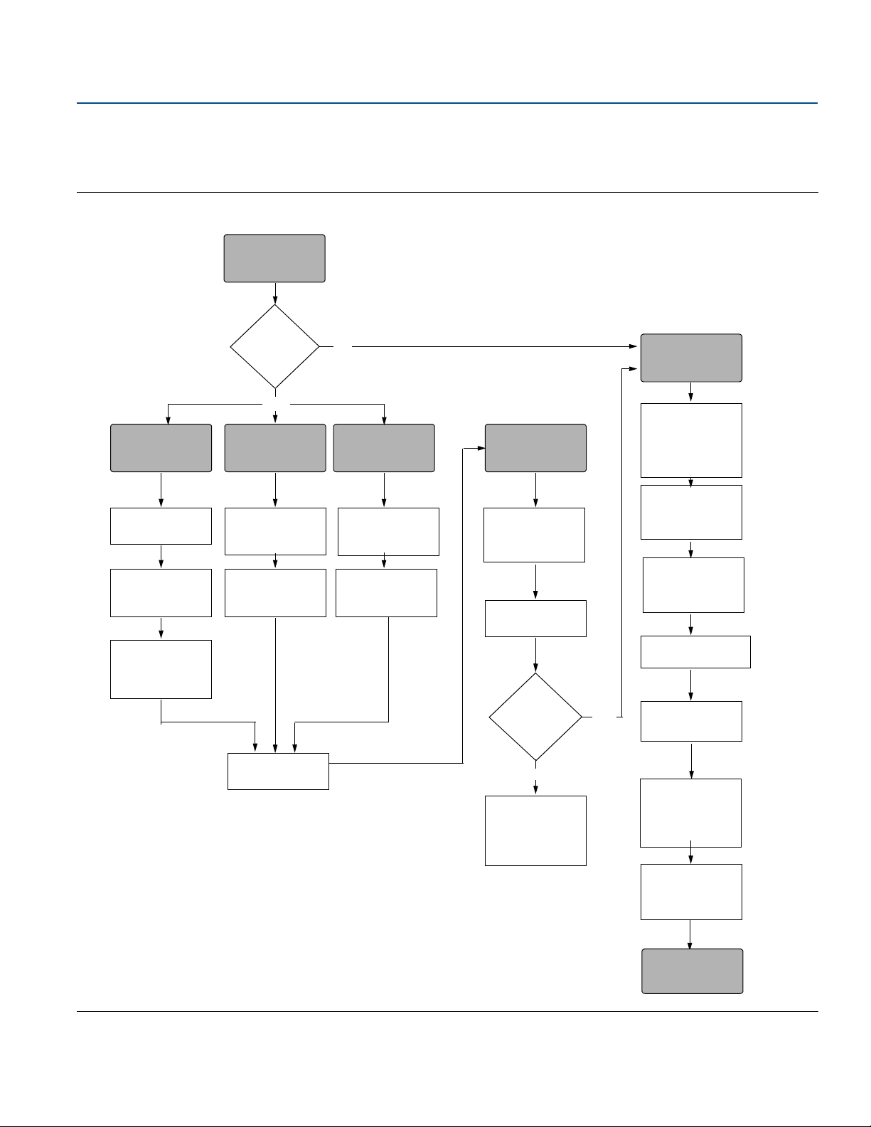
START HERE
Bench
calibration?
Field Install
No
Set Units
(page 13)
Set Range Points
(page 15)
Select Linear
Output
(page 13)
Set Damping
(page 17)
Ver ify
Apply Pressure
Yes
Within
specifications?
Yes
No
Refer to
Section 5:
Operation and
Maintenance
Configure
Security and
Alarm
(page 50)
Mount Transmitter
(page 30)
Wire Transmitter
(page 55)
Power Transmitter
(page 54)
Tri m the
Tra ns mi tt er
(page 66)
Done
Review Transmitter
Configuration
(page 11)
Confirm
Tra ns mi tt er
Configuration
(page 11)
Configure for
Pressure
Configure Scaled
Var iable
(page 22)
Set Scaled
Variable to PV
(page 22)
Configure for Level Configure for Flow
Configure Scaled
Var iable
(page 22)
Set Scaled
Variable to PV
(page 22)
Check Process
Connection
(page 37)
00809-0100-4107, Rev CA
1.3 HART installation flowchart
Figure 1-1. HART Installation Flowchart
Introduction
July 2017
Introduction
3
Page 14
Introduction
July 2017
1.4 Transmitter overview
The Rosemount 2051C Coplanar™ design is offered for Differential Pressure (DP) and Gage Pressure (GP)
measurements. The Rosemount 2051C utilizes capacitance sensor technology for DP and GP
measurements. The Rosemount 2051T utilizes piezoresistive sensor technology for AP and GP
measurements.
The major components of the Rosemount 2051 are the sensor module and the electronics housing. The
sensor module contains the oil filled sensor system (isolating diaphragms, oil fill system, and sensor) and
the sensor electronics. The sensor electronics are installed within the sensor module and include a
temperature sensor, a memory module, and the analog to digital signal converter (A/D converter). The
electrical signals from the sensor module are transmitted to the output electronics in the electronics
housing. The electronics housing contains the output electronics board, the optional external
configuration buttons, and the terminal block. The basic block diagram of the Rosemount 2051CD is
illustrated in Figure 1-3 on page 5.
For the Rosemount 2051, pressure is applied to the isolating diaphragm(s). The oil deflects the sensor
which then changes its capacitance or voltage signal. This signal is then changed to a digital signal by the
Signal Processing. The microprocessor then takes the signals from the Signal Processing and calculates
the correct output of the transmitter. This signal is then sent to the D/A converter, which converts the
signal back to the analog signal, then superimposes the HART signal on the 4—20 mA output.
Reference Manual
00809-0100-4107, Rev CA
An optional LCD can be ordered that connects directly to the interface board which maintains direct
access to the signal terminals. The display indicates output and abbreviated diagnostic messages. A glass
display cover is provided. For 4—20 mA HART output, the LCD Display features a two-line display. The first
line displays the actual measured value, the second line of six characters displays the engineering units.
The LCD can also display diagnostic messages.
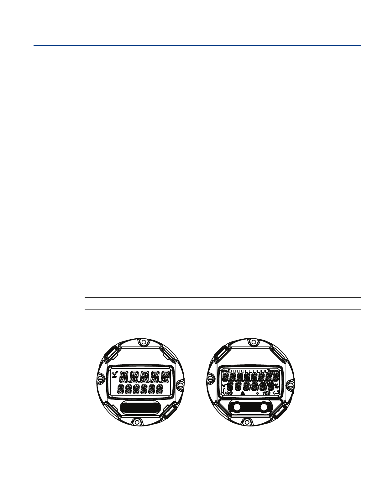
Note
LCD Display utilizes a 5 x 6 character display and can display output and diagnostic messages. The LOI
Display uses an 8 x 6 character display and can display output, diagnostic messages, and LOI menu
screens. The LOI Display comes with two buttons mounted on the front of the display board. See below
figure.
Figure 1-2. LOI/LCD Display
LCD Display LOI Display
4
Introduction
Page 15
Reference Manual
ABC
D
Signal Processing
Tem p.
Sensor
Sensor Module
Memory
Microprocessor
• Sensor linearization
• Rerange
• Damping
• Diagnostics
• Engineering units
• Communication
Digital-to
Analog Signal
Conversion
Digital
Communication
Memory
• Configuration
00809-0100-4107, Rev CA
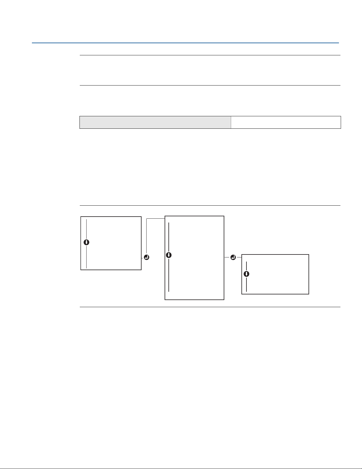
Figure 1-3. Block Diagram of Operation
Introduction
July 2017
1.5 Service support
A. Sensor module
B. Electronics board
C. 4—20 mA signal to control system
D. Field Communicator
Within the United States, call the Emerson Instrument and Valve Response Center using the
1-800-654-RSMT (7768) toll-free number. This center, available 24 hours a day, will assist you with any
needed information or materials.
The center will ask for product model and serial numbers, and will provide a Return Material
Authorization (RMA) number. The center will also ask for the process material to which the product was
last exposed.
For inquiries outside of the United States, contact the nearest Emerson representative for RMA
instructions.
To expedite the return process outside of the United States, contact the nearest Emerson representative.
Individuals who handle products exposed to a hazardous substance can avoid injury if they are
informed of and understand the hazard. The product being returned will require a copy of the
required Material Safety Data Sheet (MSDS) for each substance must be included with the returned
goods.
Emerson Instrument and Valve Response Center representatives will explain the additional information
and procedures necessary to return goods exposed to hazardous substances.
Introduction
5
Page 16

Introduction
July 2017
1.6 Product recycling/disposal
Recycling of equipment and packaging should be taken into consideration and disposed of in accordance
with local and national legislation/regulations.
Reference Manual
00809-0100-4107, Rev CA
6
Introduction
Page 17

Reference Manual
00809-0100-4107, Rev CA
Section 2 Configuration
Configuration overview . . . . . . . . . . . . . . . . . . . . . . . . . . . . . . . . . . . . . . . . . . . . . . . . . . . . . . . . . . . . . . . . page 7
Safety messages . . . . . . . . . . . . . . . . . . . . . . . . . . . . . . . . . . . . . . . . . . . . . . . . . . . . . . . . . . . . . . . . . . . . . . page 7
System readiness . . . . . . . . . . . . . . . . . . . . . . . . . . . . . . . . . . . . . . . . . . . . . . . . . . . . . . . . . . . . . . . . . . . . . page 8
Configuration basics . . . . . . . . . . . . . . . . . . . . . . . . . . . . . . . . . . . . . . . . . . . . . . . . . . . . . . . . . . . . . . . . . . page 9
Verify configuration . . . . . . . . . . . . . . . . . . . . . . . . . . . . . . . . . . . . . . . . . . . . . . . . . . . . . . . . . . . . . . . . . . . page 11
Basic setup of the transmitter . . . . . . . . . . . . . . . . . . . . . . . . . . . . . . . . . . . . . . . . . . . . . . . . . . . . . . . . . . page 13
Configuring the LCD display . . . . . . . . . . . . . . . . . . . . . . . . . . . . . . . . . . . . . . . . . . . . . . . . . . . . . . . . . . . . page 18
Detailed transmitter setup . . . . . . . . . . . . . . . . . . . . . . . . . . . . . . . . . . . . . . . . . . . . . . . . . . . . . . . . . . . . . page 19
Performing transmitter tests . . . . . . . . . . . . . . . . . . . . . . . . . . . . . . . . . . . . . . . . . . . . . . . . . . . . . . . . . . . page 24
Configuring burst mode . . . . . . . . . . . . . . . . . . . . . . . . . . . . . . . . . . . . . . . . . . . . . . . . . . . . . . . . . . . . . . . page 25
Establishing multidrop communication . . . . . . . . . . . . . . . . . . . . . . . . . . . . . . . . . . . . . . . . . . . . . . . . . . page 26
Configuration
July 2017
2.1 Configuration overview
This section contains information on commissioning and tasks that should be performed on the bench
prior to installation, as well as tasks performed after installation as described in “Performing transmitter
tests” on page 24.
Field Communicator, AMS
perform configuration functions. For convenience, Field Communicator Fast Key sequences are labeled
“Fast Keys,” and abbreviated LOI menus are provided for each function below.
Full Field Communicator menu trees and Fast Key sequences are available in Appendix C: Field
Communicator Menu Trees and Fast Keys. LOI menu trees are available in Appendix D: Local Operator
Interface.
™
Device Manager, and Local Operator Interface (LOI) instructions are given to
2.2 Safety messages
Procedures and instructions in this section may require special precautions to ensure the safety of the
personnel performing the operations. Information that raises potential safety issues is indicated by a
warning symbol ( ). Refer to the following safety messages before performing an operation preceded
by this symbol.
Config uration
7
Page 18

Configuration
July 2017
Reference Manual
00809-0100-4107, Rev CA
Explosions could result in death or serious injury.
Installation of this transmitter in an explosive environment must be in accordance with the appropriate
local, national, and international standards, codes, and practices. Review the approvals section of the
Rosemount
Before connecting a Field Communicator in an explosive atmosphere, ensure the instruments in the
loop are installed in accordance with intrinsically safe or non-incendive field wiring practices.
In an explosion-proof/flameproof installation, do not remove the transmitter covers when power is
applied to the unit.
Process leaks may cause harm or result in death.
Install and tighten process connectors before applying pressure.
Electrical shock can result in death or serious injury.
Avoid contact with the leads and terminals. High voltage that may be present on leads can cause
electrical shock.
™
2051 reference manual for any restrictions associated with a safe installation.
2.3 System readiness
If using HART
such systems prior to commissioning and installation. Not all systems are capable of communicating
with HART Revision 7 devices.
For instructions on how to change the HART revision of your transmitter, see “Switching HART
Revision” on page 72.
2.3.1 Confirm correct Device Driver
1. Verify the latest Device Driver (DD/DTM™) is loaded on your systems to ensure proper
communications.
2. Reference Emerson.com
3. In the browse by member dropdown menu, select Rosemount business unit of Emerson
4. Select desired Product
a. Within Ta b le 2 - 1 , use the HART Universal Revision and Device Revision numbers to find the
correct Device Driver
Table 2-1. Rosemount 2051 Device Revisions and Files
Software
release date
August 2012 1.0.0 01
January 1998 N/A 178 5 3
1. NAMUR Soft ware Revision is located on the hardware tag of the device
2. HART Soft ware Revision can be read using a HART capable configuration tool.
3. Device Driver file names use Device and DD Revision, e.g. 10_01. HART Protocol is designed to enable legacy device driver revisions to
continue to communicate with new HART devices. To access new functionality, the new Device Driver must be downloaded. It is
recommended to download new Device Driver files to ensure full functionality.
8
®
based control or asset management systems, confirm the HART Protocol capability of
or FieldCommGroup.org for the latest DD.
Identify device Find Device Driver
NAMUR
software
revision
(1)
HART
software
revision
(2)
HART
universal
revision
Device
revision
7 10
5 9
instructions
Reference
(3)
Rosemount 2051
Reference Manual
Rosemount 2051
Reference Manual
Review
manual
™
.
Review
functionality
Changes to
software
(4)
N/A
Configuration
Page 19
Reference Manual
A
B
00809-0100-4107, Rev CA
4. HART Revision 5 and 7 Selec table, Safety Certified, Local Operator Interface, Scaled Variable, Configurable Alarms,
Expanded Engineering Units.
2.4 Configuration basics
Set all transmitter hardware adjustments during commissioning to avoid exposing the transmitter
electronics to the plant environment after installation.
The Rosemount 2051 can be configured either before or after installation. Configuring the transmitter
on the bench using either a Field Communicator, AMS Device Manager, or LOI ensures all transmitter
components are in working order prior to installation. Verify that the security switch is set in the unlock
position ( ) in order to proceed with configuration. See Figure 4-2 on page 51 for switch location.
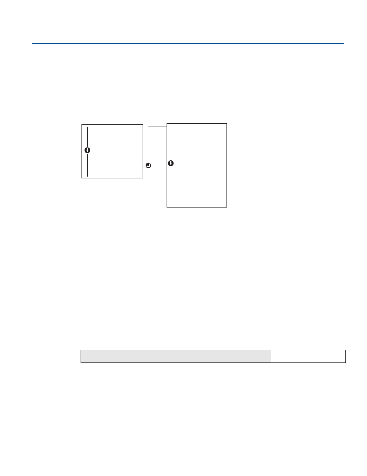
2.4.1 Configuring on the bench
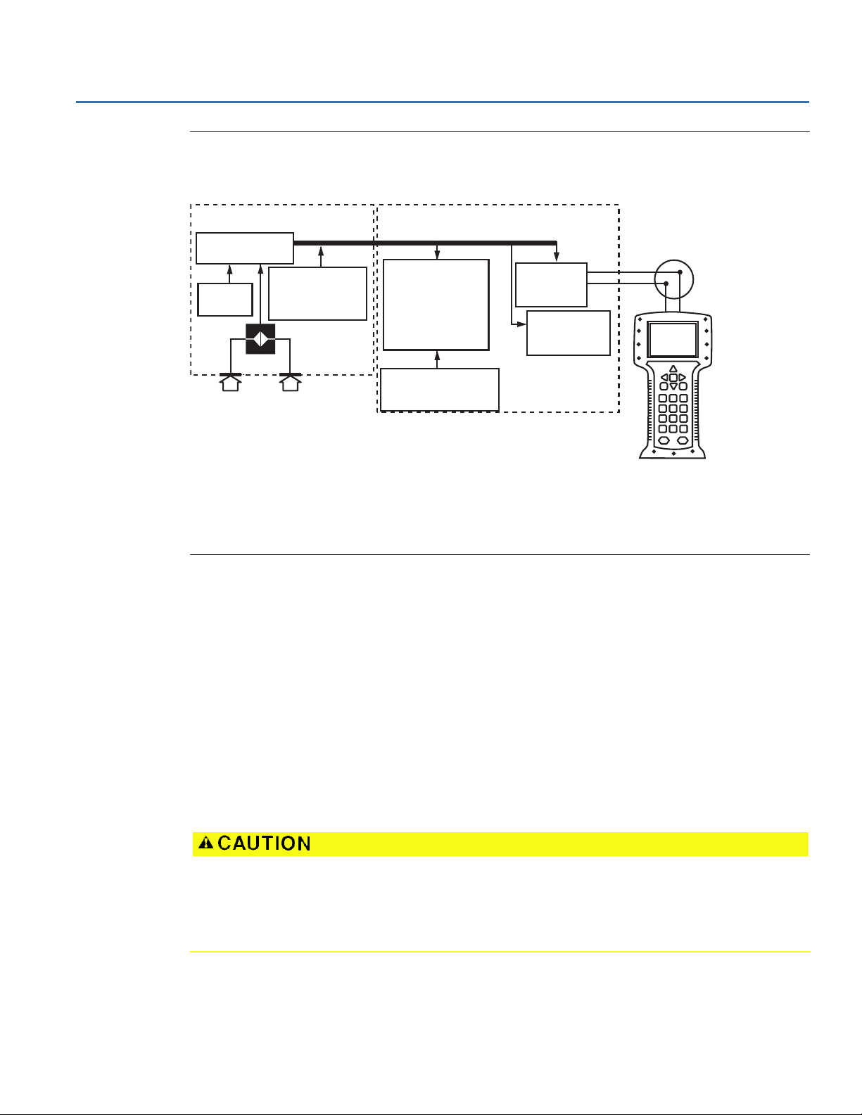
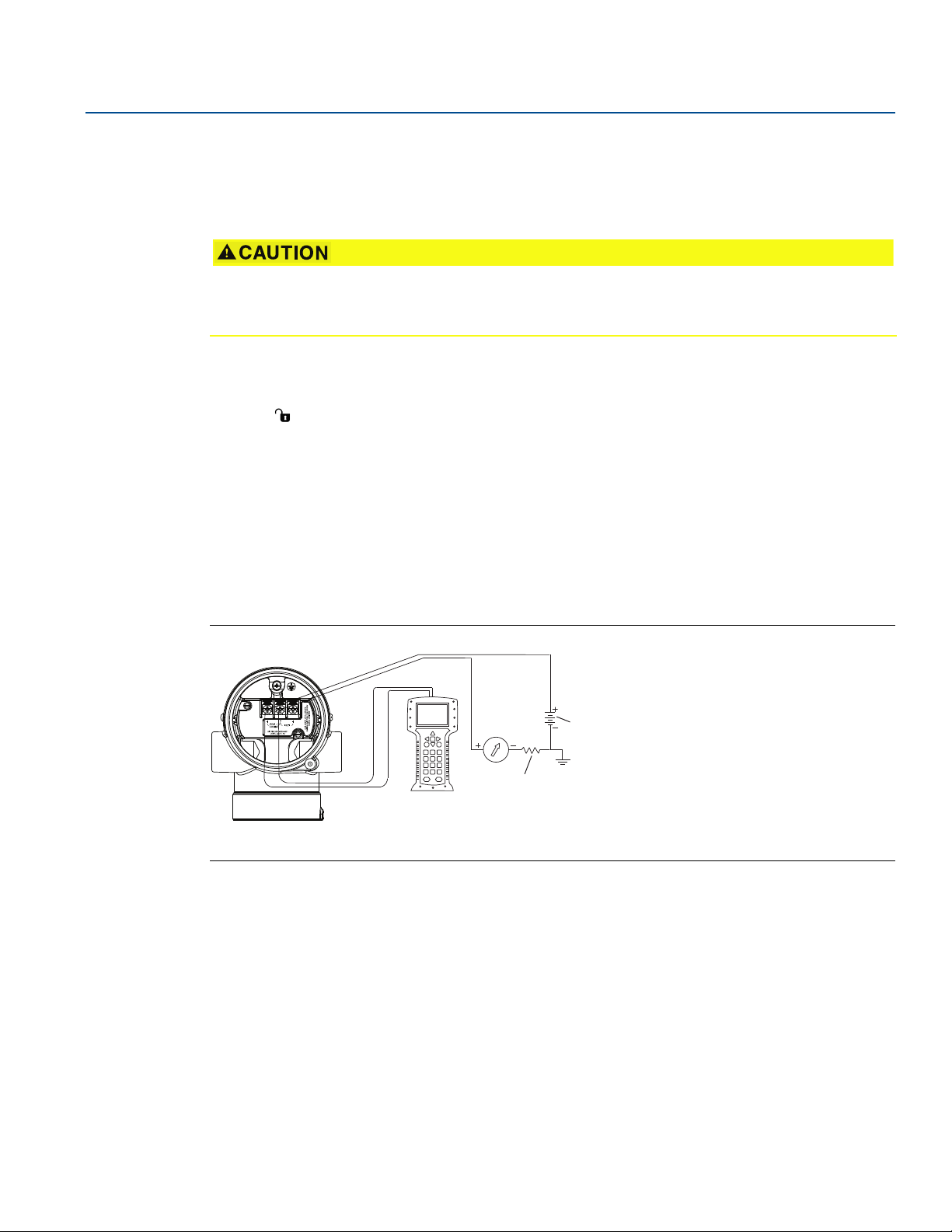
To configure on the bench, required equipment includes a power supply, and a Field Communicator,
AMS Device Manager, or an LOI (option M4). Wire equipment as shown in figure below. To ensure
successful HART communication, a resistance of at least 250 s must be present between the
transmitter and the power supply, see “Power supply” on page 54 for details. Connect the Field
Communicator leads to the terminals labeled “COMM” on the terminal block or 1—5 V configuration,
wire as shown in Figure 2-1 on page 9. The Field communicator is connected to the terminals labeled
VOUT/COMM.
Configuration
July 2017
Figure 2-1. Wiring the Transmitter (4—20 mA HART Protocol)
A. Vdc supply
B. R
250 (necessary for HART communication only)
L
Config uration
9
Page 20
Configuration
A
B
SAVE
1. Overview
2. Configure
3. Service Tools
2051 FT 45B
Online
July 2017
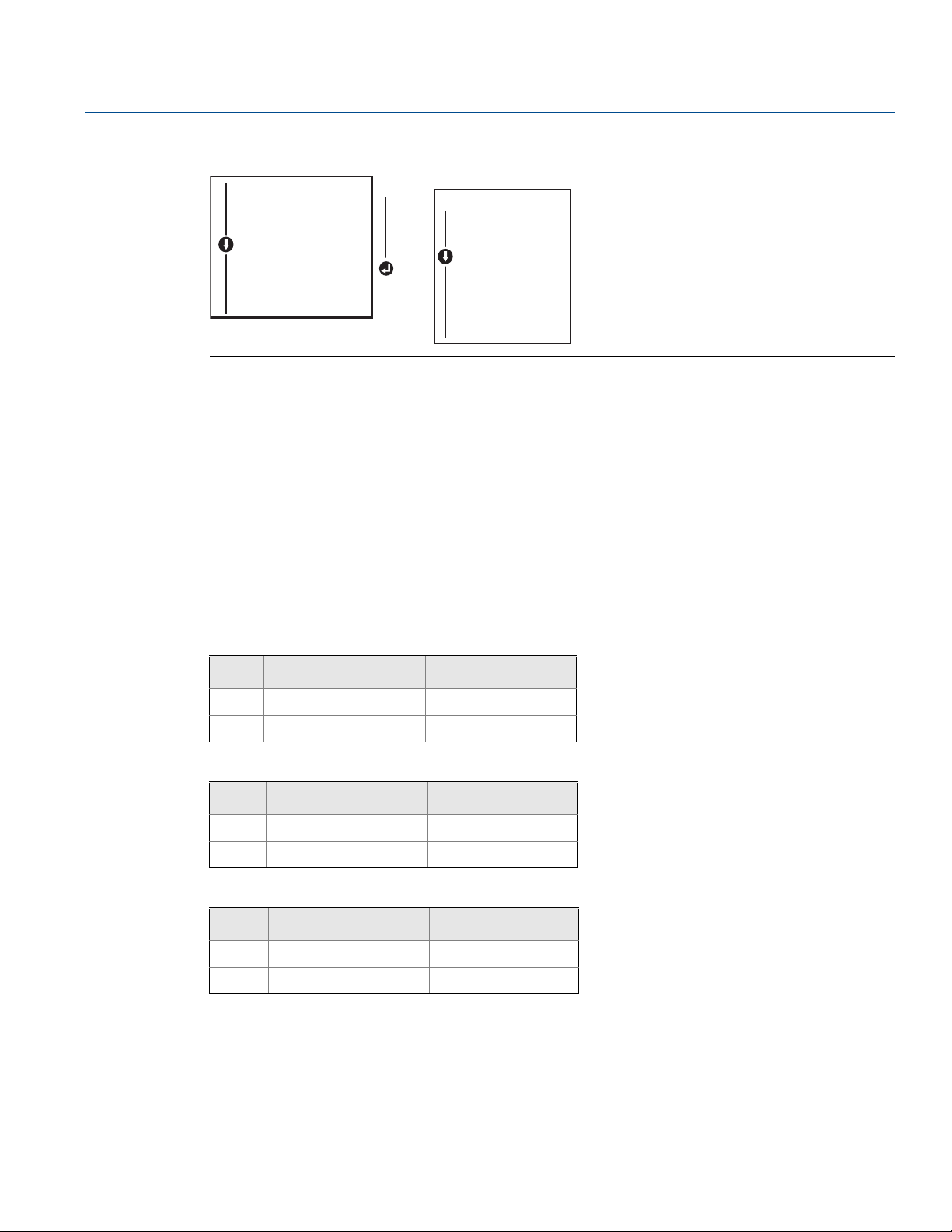
2.4.2 Configuration tools
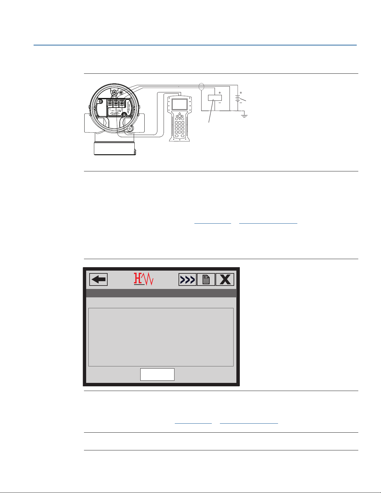
Figure 2-2. Wiring the Transmitter (1—5 Vdc Low Power)
A. DC power supply
B. Voltmeter
Configuring with a Field Communicator
There are two interfaces available with the Field Communicator: Traditional and dashboard interfaces. All
steps using a Field Communicator will be described using Dashboard interfaces. Figure 2-3 on page 10
shows the Device Dashboard interface. As stated in System readiness , it is critical that the latest DD’s are
loaded into the Field Communicator. Visit Emerson.com
library.
Reference Manual
00809-0100-4107, Rev CA
or FieldCommGroup.org to download latest DD
Field Communicator menu trees and Fast Keys are available in Appendix C: Field Communicator Menu
Trees and Fast Keys.
Figure 2-3. Device Dashboard
Configuring with AMS Device Manager
Full configuration capability with AMS Device Manager requires loading the most current DD for this
device. Download the latest DD at Emerson.com
Note
All steps using AMS Device Manager will be described using version 11.5.
or FieldCommGroup.org.
10
Configuration
Page 21
Reference Manual
B
00809-0100-4107, Rev CA
Configuring with a LOI
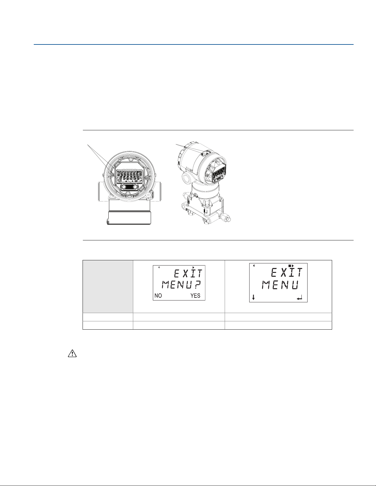
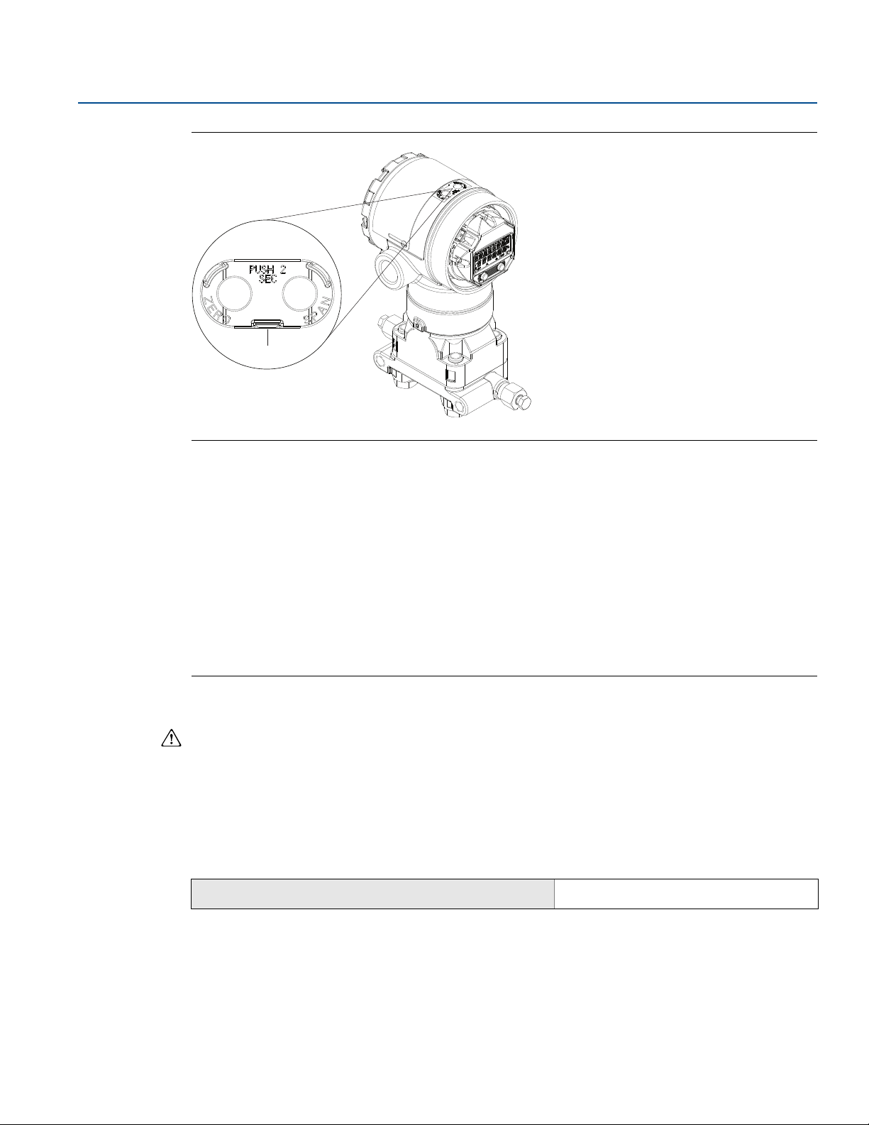
The LOI requires option code M4 to be ordered. To activate the LOI push either configuration button.
Configuration buttons are located on the LCD display (must remove housing cover to access), or
underneath the top tag of the transmitter. See Ta b l e 2- 2 for configuration button functionality and
Figure 2-4 for configuration button location. When using the LOI for configuration, several features
require multiple screens for a successful configuration. Data entered will be saved on a screen-by-screen
basis; the LOI will indicate this by flashing “SAVED” on the LCD display each time.
LOI menu trees are available in Appendix D: Local Operator Interface.
Figure 2-4. LOI Configuration Buttons
A
Configuration
July 2017
A. Internal configuration buttons
B. External configuration buttons
Table 2-2. LOI Button Operation
Button
Left No SCROLL
Right Yes ENTER
2.4.3 Setting the loop to manual
Whenever sending or requesting data that would disrupt the loop or change the output of the
transmitter, set the process application loop to manual control. The Field Communicator, AMS Device
Manager, or the LOI will prompt you to set the loop to manual when necessary. The prompt is only a
reminder; acknowledging this prompt does not set the loop to manual. It is necessary to set the loop to
manual control as a separate operation.
2.5 Verify configuration
Config uration
It is recommended that various configuration parameters are verified prior to installation into the
process. The various parameters are detailed out for each configuration tool. Depending on what
configuration tool(s) are available follow the steps listed relevant to each tool.
11
Page 22

Configuration
July 2017
2.5.1 Verifying configuration with Field Communicator
Configuration parameters listed in Ta bl e 2 - 3 are to be reviewed prior to transmitter installation. A Full list
of configuration parameters that can be reviewed and configured using a Field Communicator are
located in Appendix C: Field Communicator Menu Trees and Fast Keys.
Fast Key sequences for the latest DD are shown in Tab l e 2 -3 . For Fast Key sequences for legacy DD's
contact your local Emerson.
Table 2-3. Rosemount 2051 Device Dashboard Fast Key Sequence
From the HOME screen, enter the Fast Key sequences listed
Fast Key Sequence
Reference Manual
00809-0100-4107, Rev CA
Function
Alarm and Saturation Levels 2, 2, 2, 5 2, 2, 2, 5
Damping 2, 2, 1, 1, 5 2, 2, 1, 1, 5
Primary Variable 2, 1, 1, 4, 1 2, 1, 1, 4, 1
Range Values 2, 1, 1, 4 2, 1, 1, 4
Ta g 2, 2, 7, 1, 1 2, 2, 7, 1, 1
Tra nsfer Fu nctio n 2, 2, 1, 1, 6 2, 2, 1, 1, 6
Units 2, 2, 1, 1, 4 2, 2, 1, 1, 4
HART 7 HART 5
2.5.2 Verifying configuration with AMS Device Manager
Right click on the device and select Configuration Properties from the menu. Navigate the tabs to
review the transmitter configuration data.
2.5.3 Verifying configuration with LOI
Select any configuration button to activate the LOI. Select VIEW CONFIG to review the below
parameters. Use the configuration buttons to navigate through the menu.
reviewed prior to installation include:
Tag Primary variable
Units Range values
Transfer function Damping
Alarm and saturation
levels
The parameters to be
2.5.4 Verifying process variables configuration
This section describes how to verify that the correct process variables are selected.
Verifying process variables with a Field Communicator
From the HOME screen, enter the Fast Key sequence
Device Dashboard Fast Keys
Verifying process variables with AMS Device Manager
Right click on the device and select Overview from the menu.
1. Select the All Variables button to display the primary, secondary, tertiary and quaternary variables.
12
3, 2, 1
Configuration
Page 23
Reference Manual
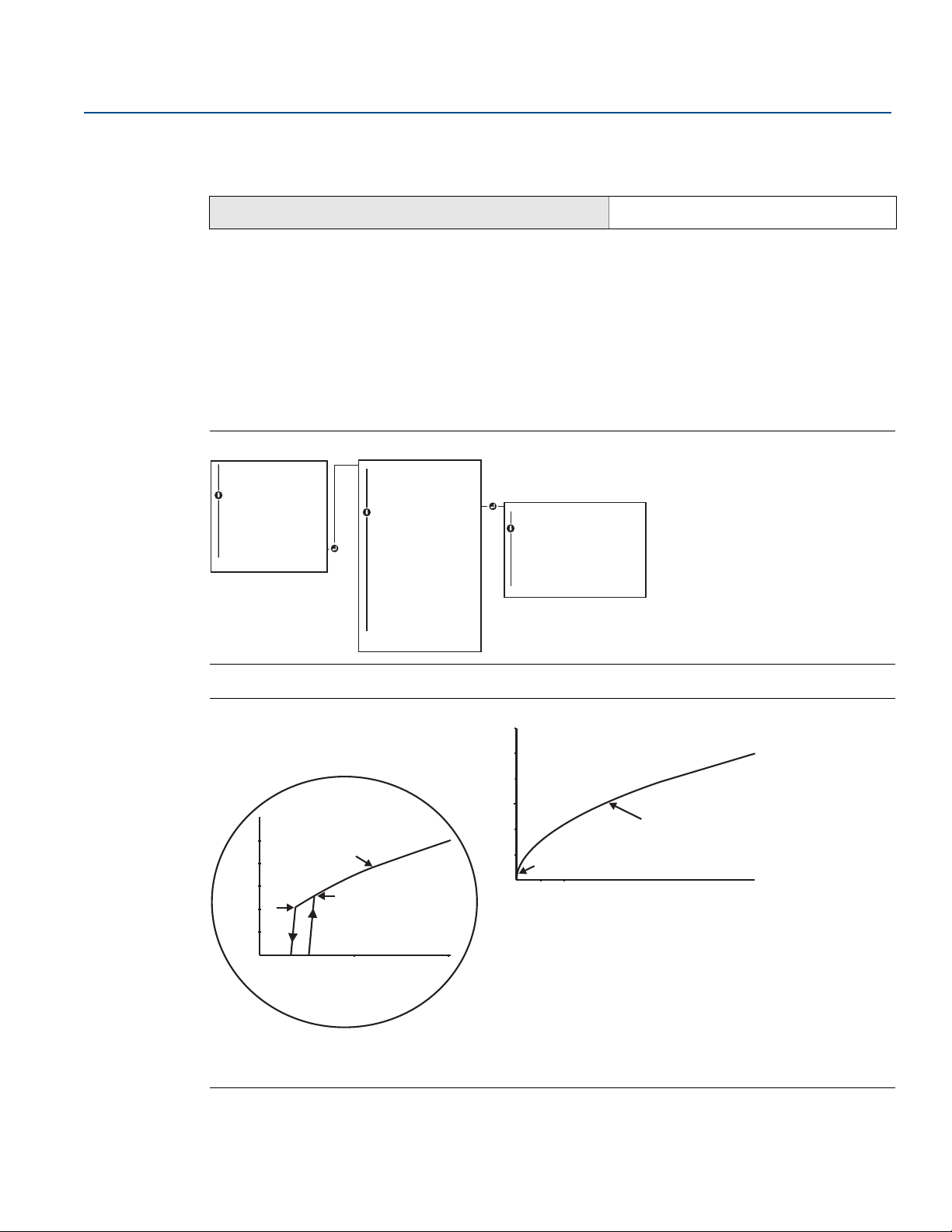
UNITS
PRESS UNITS
PRESS UNITS
TEMP UNITS
BACK TO MENU
EXIT MENU
PRESS UNITS
INH2O
MMHG
CMHG0C
MHG0C
PSI
PSF
ATM
TORR
PA
KPA
...
VIEW CONFIG
ZERO TRIM
UNITS
UNITS
RERANGE
LOOP TEST
DISPLAY
EXTENDED MENU
EXIT MENU
00809-0100-4107, Rev CA
2.6 Basic setup of the transmitter
This section goes through the necessary steps for basic setup of a pressure transmitter. When installing
in DP level or DP flow applications, refer to“Configuring Scaled Variable” on page 20 for setup
instructions.
2.6.1 Setting pressure units
The pressure unit command sets the unit of measure for the reported pressure.
Setting pressure units with a Field Communicator
From the HOME screen, enter the Fast Key sequence
Device Dashboard Fast Keys
Setting pressure units with AMS Device Manager
Right click on the device and select Configure.
1. Select Manual Setup and select desired units from Pressure Units dropdown menu.
Configuration
July 2017
2, 2, 1, 1, 4
2. Select Send when complete.
Setting pressure units with a LOI
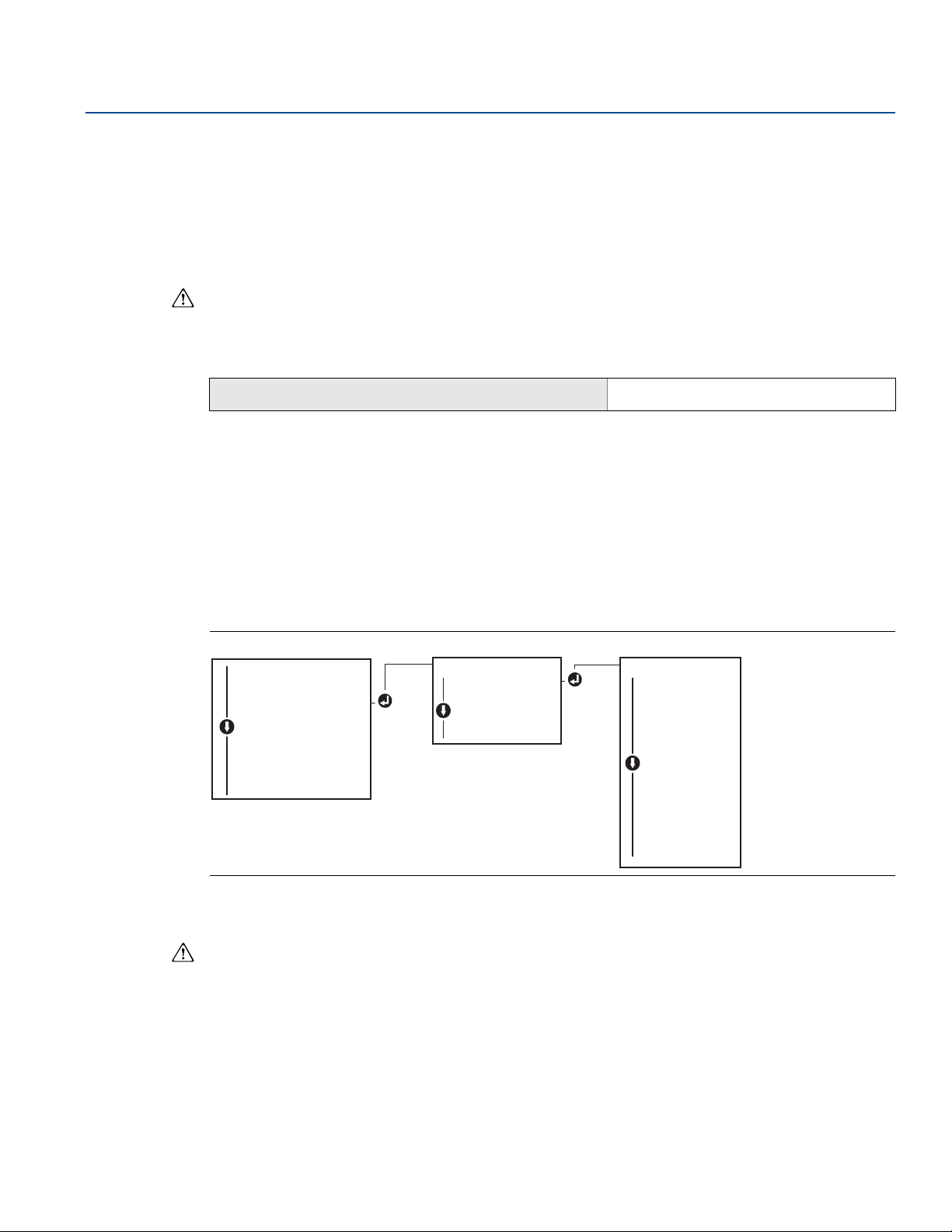
Follow Figure 2-5 on page 13 to select desired pressure and temperature units. Use the SCROLL and
ENTER buttons to select desired unit. Save by selecting SAVE as indicated on the LCD display.
Figure 2-5. Selecting Units with LOI
2.6.2 Setting transmitter output (transfer function)
The Rosemount 2051 has two output settings: Linear and square root. As shown in Figure 2-7 on
page 14, activating the square root options makes analog output proportional to flow, and includes a
fixed low flow cutoff at five percent.
Config uration
However, for DP Flow and DP Level applications it is recommended to use scaled variable. Refer to
“Configuring Scaled Variable” on page 20 for setup instructions.
13
Page 24
Configuration
EXTENDED MENU
CALIBRAT
DAMPING
TRANSFER FUNCT
TRANSFER FUNCT
SCALED VARIAB
ASSIGN PV
TAG
ALARM SAT
VAL UES
PASSWORD
SIMLATE
HART REV
BACK TO MENU
EXIT MENU
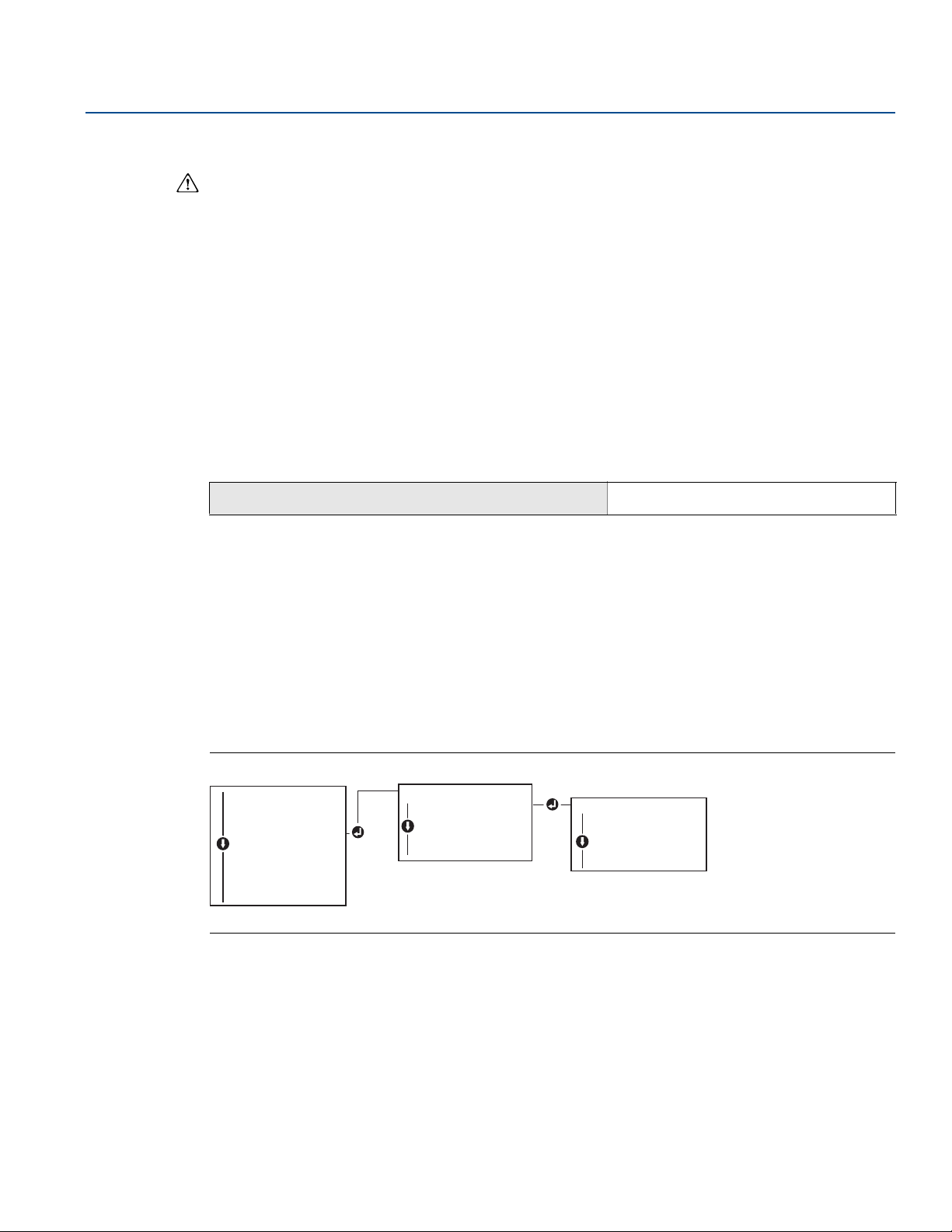
TRANSFER FUNCT
LINEAR TRANSFER
FUNCTION
SQR ROOT TRANSFER
FUNCTION
BACK TO MENU
EXIT MENU
VIEW CONFIG
ZERO TRIM
UNITS
RERANGE
LOOP TEST
DISPLAY
EXTENDED MENU
EXTENDED MENU
EXIT MENU
A
B
C
0.5 1
% Pressure Input
0
0 102030 4050 60 708090100
4 mA
20mA
% Pressure Input
B
A
4 mA
July 2017
Reference Manual
00809-0100-4107, Rev CA
Setting transmitter output with a Field Communicator
From the HOME screen, enter the Fast Key sequence
Device Dashboard Fast Keys
2, 2, 1, 1, 6
Setting transmitter output with AMS Device Manager
Right click on the device and select Configure.
1. Select Manual Setup and choose output type from analog output transfer function and select Send.
2. Carefully read the warning and select Ye s if it is safe to apply the changes.
Setting transmitter output with a LOI
Reference Figure 2-6 on page 14 to select either linear or square root transfer function using the LOI.
Figure 2-6. Set Output with LOI
14
Figure 2-7. 4—20 mA HART Square Root Output Transition Point
A. Square root curve
B. Five percent transition point
C. Four percent transition point
Configuration
Page 25
Reference Manual
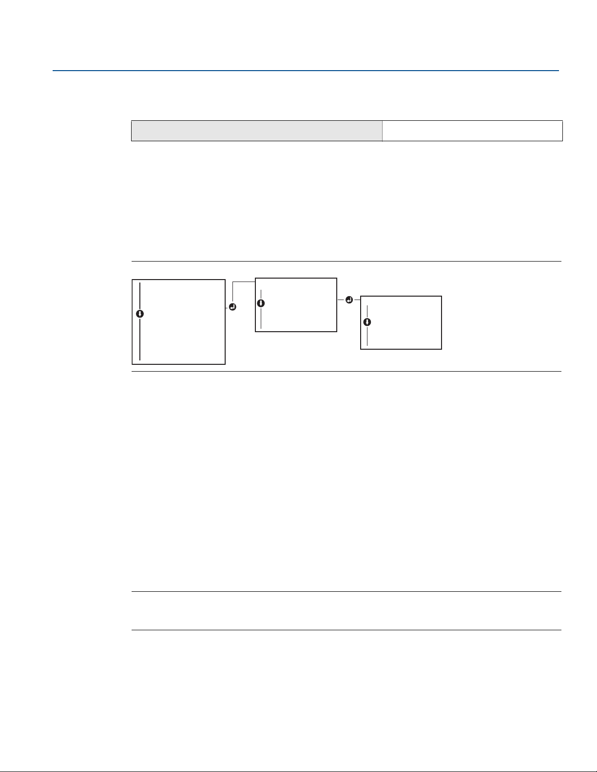
RERANGE
ENTER VALUES
ENTER VALUES
APPLY VALUES
BACK TO MENU
EXIT MENU
ENTER VALUES
LRV
URV
BACK TO MENU
EXIT MENU
VIEW CONFIG
ZERO TRIM
UNITS
RERANGE
RERANGE
LOOP TEST
DISPLAY
EXTENDED MENU
EXIT MENU
00809-0100-4107, Rev CA
2.6.3 Rerange the transmitter
The Range Values command sets each of the lower and upper range analog values (4 and 20 mA/1—5 Vdc
points) to a pressure. The lower range point represents zero percent of range and the upper range point
represents 100 percent of range. In practice, the transmitter range values may be changed as often as
necessary to reflect changing process requirements. For a complete listing of range and sensor limits,
refer to “Range and sensor limits” on page 95.
Select from one of the methods below to rerange the transmitter. Each method is unique; examine all
options closely before deciding which method works best for your process.
Rerange by manually setting range points with a Field Communicator, AMS Device Manager, or LOI.
Rerange with a pressure input source and a Field Communicator, AMS Device Manager, LOI, or local
zero and span buttons.
Manually rerange the transmitter by entering range points
Entering range points with a Field Communicator
From the HOME screen, enter the Fast Key sequence
Configuration
July 2017
Device Dashboard Fast Keys
2, 2, 2, 1
Entering range points with AMS Device Manager
Right click on the device and select Configure:
1. Select Manual Setup and select Analog Output.
2. Enter upper and lower range values in the Range Limits box and select Send.
3. Carefully read the warning and select Ye s if it is safe to apply the changes.
Entering range points with a LOI
Reference Figure 2-8 on page 15 to rerange the transmitter using the LOI. Enter values using SCROLL and
ENTER buttons.
Figure 2-8. Rerange with LOI
Config uration
Rerange the transmitter with applied pressure source
Reranging using an applied pressure source is a way of reranging the transmitter without entering
specific 4 and 20 mA (1—5 Vdc) points.
15
Page 26
Configuration
RERANGE
ENTER VALUES
APPLY VALUES
APPLY VALUES
BACK TO MENU
EXIT MENU
APPLY VALUES
LRV
URV
BACK TO MENU
EXIT MENU
VIEW CONFIG
ZERO TRIM
UNITS
RERANGE
RERANGE
LOOP TEST
DISPLAY
EXTENDED MENU
EXIT MENU
July 2017
Reference Manual
00809-0100-4107, Rev CA
Field Communicator
From the HOME screen, enter the Fast Key sequence
Device Dashboard Fast Keys
2, 2, 2, 2
Rerange with an applied pressure source using AMS Device Manager
Right click on the device, select Configure.
1. Select the Analog Output tab.
2. Select Range by Applying Pressure button and follow the screen prompts range the transmitter.
Rerange with an applied pressure source using an LOI
Use Figure 2-9 to manually rerange the device using an applied pressure source with an LOI.
Figure 2-9. Rerange with Applied Pressure Using LOI
Rerange with an applied pressure source using local zero and span buttons
If ordered, local zero and span buttons (option code D4) can be used to rerange the transmitter with an
applied pressure. Refer to Figure 2-10 on page 17 for analog zero and span button location.
To rerange the transmitter using the span and zero buttons, perform the following procedure:
1. Loosen the screw holding the top tag of the transmitter housing. Rotate the label to expose the zero
and span buttons.
2. Confirm device has local zero and span buttons by verifying blue retainer under the tag.
3. Apply transmitter pressure.
4. Rerange the transmitter.
a. To change the zero (4 mA/1 V point) while maintaining the span: press and hold zero button for at
least two seconds then release.
b. To change the span (20 mA/5 V point) while maintaining the zero point: press and hold the span
button for at least two seconds and then release.
Note
4 mA and 20 mA points must maintain the minimum span defined in Appendix A: Specifications and
Reference Data.
16
Configuration
Page 27
Reference Manual
A
00809-0100-4107, Rev CA
Figure 2-10. Analog Zero and Span Buttons
A. Zero and span buttons
Configuration
July 2017
If the transmitter security is on, adjustments to the zero and span will not be able to be made. Refer to
“Configure security and simulation” on page 50 for security information.
The span is maintained when the 4 mA/1 V point is set. The span changes when the 20 mA/5 V point is
set. If the lower range point is set to a value that causes the upper range point to exceed the sensor
limit, the upper range point is automatically set to the sensor limit, and the span is adjusted
accordingly.
Regardless of the range points, the Rosemount 2051 will measure and report all readings within the
digital limits of the sensor. For example, if the 4 and 20 mA(1—5 Vdc) points are set to 0 and 10 inH
and the transmitter detects a pressure of 25 inH
percent of range reading.
2.6.4 Damping
The damping command changes the response time of the transmitter; higher values can smooth
variations in output readings caused by rapid input changes. Determine the appropriate damping setting
based on the necessary response time, signal stability, and other requirements of the loop dynamics
within your system. The damping command utilizes floating point configuration allowing the user to
input any damping value within 0.0—60.0 seconds.
Damping with a Field Communicator
From the HOME screen, enter the Fast Key sequence
Device Dashboard Fast Keys
O, it digitally outputs the 25 inH2O reading and a 250
2
2, 2, 1, 1, 5
2
O,
Config uration
Enter desired Damping Value and select APPLY.
Damping with AMS Device Manager
Right select on the device and select Configure.
17
Page 28
Configuration
EXTENDED MENU
CALIBRAT
DAMPING
DAMPING
TRANSFER FUNCT
SCALED VARIAB
ASSIGN PV
TAG
ALARM SAT VALUES
PASSWORD
SIMLATE
HART REV
BACK TO MENU
EXIT MENU
VIEW CONFIG
ZERO TRIM
UNITS
RERANGE
LOOP TEST
DISPLAY
EXTENDED MENU
EXTENDED MENU
EXIT MENU
July 2017
Reference Manual
00809-0100-4107, Rev CA
1. Select Manual Setup.
2. Within the Pressure Setup box, enter desired damping value and select Send.
3. Carefully read the warning and select Ye s if it is safe to apply the changes.
Damping with a LOI
Reference Figure 2-11 to enter damping values using an LOI.
Figure 2-11. Damping with LOI
2.7 Configuring the LCD display
18
The LCD display configuration command allows customization of the LCD display to suit application
requirements. The LCD display will alternate between the selected items.
Pressure units Sensor temperature
% of range mA/Vdc output
Scaled variable
In the following instructions, the LCD display can also be configured to display configuration information
during the device startup. Select Review Parameters at Startup to enable or disable this functionality.
Reference Figure 1-2 on page 4 LCD display with LOI for image of LCD screen.
Configuring LCD Display with a Field Communicator
From the HOME screen, enter the Fast Key sequence
Device Dashboard Fast Keys
2, 2, 4
Configuring LCD display with AMS Device Manager
Right click on the device and select Configure.
1. Select Manual Setup, select the Display tab.
2. Select desired display options and select Send.
Configuring LCD display with a LOI
Refer to Figure 2-12 for LCD display configuration using a LOI.
Configuration
Page 29
Reference Manual
DISPLAY
PRESS (on/off)
SCALED (on/off)
TEMP (on/off)
%RANGE (on/off)
ANALOG (on/off)
STRTUP (on/off)
BACK TO MENU
EXIT MENU
VIEW CONFIG
ZERO TRIM
UNITS
RERANGE
LOOP TEST
DISPLAY
DISPLAY
EXTENDED MENU
EXIT MENU
00809-0100-4107, Rev CA
Figure 2-12. Display with LOI
2.8 Detailed transmitter setup
2.8.1 Configuring alarm and saturation levels
In normal operation, the transmitter will drive the output in response to pressure from the lower to
upper saturation points. If the pressure goes outside the sensor limits, or if the output would be beyond
the saturation points, the output will be limited to the associated saturation point.
Configuration
July 2017
Config uration
The Rosemount 2051 Transmitter automatically and continuously performs self-diagnostic routines. If
the self-diagnostic routines detect a failure, the transmitter drives the output to configured alarm and
value based on the position of the alarm switch. See “Setting transmitter alarm” on page 53.
Table 2-4. Rosemount Alarm and Saturation Values
Level 4—20 mA saturation 4—20 mA alarm
Low 3.9 mA (0.97 V) 3.75 mA (0.95 V)
High 20.8 mA (5.2 V) 21.75 mA (5.4 V)
Table 2-5. NAMUR-Compliant Alarm and Saturation Values
Level 4—20 mA saturation 4—20 mA alarm
Low 3.8 mA (0.95 V) 3.6 mA (0.9 V)
High 20.5 mA (5.125 V) 22.5 mA (5.625 V)
Table 2-6. Custom Alarm and Saturation Values
Level 4—20 mA saturation 4—20 mA alarm
Low 3.7 mA to 3.9 mA 3.6 mA to 3.8 mA
High 20.1 mA to 22.9 mA 20.2 mA to 23.0 mA
Failure mode alarm and saturation levels can be configured using a Field Communicator, AMS Device
Manager, and the LOI. The following limitations exist for custom levels:
Low alarm level must be less than the low saturation level
High alarm level must be higher than the high saturation level
Alarm and saturation levels must be separated by at least 0.1 mA
The configuration tool will provide an error message if the configuration rule is violated.
19
Page 30
Configuration
EXTENDED MENU
CALIBRAT
DAMPING
TRANSFER FUNCT
SCALED VARIAB
ASSIGN PV
TAG
ALARM SAT VALUES
ALARM SAT VALUES
PASSWORD
SIMULATE
HART REV
BACK TO MENU
EXIT MENU
ALARM SAT VALUES
ROSEMOUNT VALUES
NAMUR VALUES
OTHER VALUES
BACK TO MENU
EXIT MENU
VIEW CONFIG
ZERO TRIM
UNITS
RERANGE
LOOP TEST
DISPLAY
EXTENDED MENU
EXTENDED MENU
EXIT MENU
July 2017
Reference Manual
00809-0100-4107, Rev CA
Note
Transmitters set to HART multidrop mode send all saturation and alarm information digitally; saturation
and alarm conditions will not affect the analog output. See also “Establishing multidrop
communication” on page 26.
Configuring alarm and saturation levels using a Field Communicator
From the HOME screen, enter the Fast Key sequence
Device Dashboard Fast Keys
2, 2, 2, 5
Configuring alarm and saturation levels with AMS Device Manager
Right click on the device, and select Configure.
1. Select Configure Alarm and Saturation Levels button.
2. Follow screen prompts to configure Alarm and Saturation Levels.
Configuring alarm and saturation levels using LOI
Refer to Figure 2-13 for instructions to configure alarm and saturation levels.
Figure 2-13. Configuring Alarm and Saturation with LOI
2.8.2 Configuring Scaled Variable
20
The Scaled Variable configuration allows the user to create a relationship/conversion between the
pressure units and user-defined/custom units. There are two use cases for scaled variable. The first use
case is to allow custom units to be displayed on the transmitter's LOI/LCD display. The second use case is
to allow custom units to drive the transmitter's 4—20 mA output.
If the user desires custom units to drive the 4—20 mA (1—5 Vdc) output, scaled variable must be
re-mapped as the primary variable. Refer to “Re-mapping device variables” on page 23.
Configuration
Page 31

Reference Manual
EXTENDED MENU
CALIBRAT
DAMPING
TRANSFER FUNCT
SCALED VARIAB
SCALED VARIAB
ASSIGN PV
TAG
ALARM SAT VALUES
PASSWORD
SIMLATE
HART REV
BACK TO MENU
EXIT MENU
SCALED VARIAB
VIEW SCALED
CONFIG SCALED
CONFIG SCALED
BACK TO MENU
EXIT MENU
VIEW CONFIG
ZERO TRIM
UNITS
RERANGE
LOOP TEST
DISPLAY
EXTENDED MENU
EXTENDED MENU
EXIT MENU
00809-0100-4107, Rev CA
The scaled variable configuration defines the following items:
Scaled Variable units - custom units to be displayed.
Scaled data options - defines the transfer function for the application
— Linear
— Square root
Pressure value position 1 - lower known value point with consideration of linear offset.
Scaled Variable value position 1 - custom unit equivalent to the lower known value point.
Pressure value position 2 - upper known value point.
Scaled Variable value position 2 - custom unit equivalent to the upper known value point
Linear offset - the value required to zero out pressures effecting the desired pressure reading.
Low flow cutoff - point at which output is driven to zero to prevent problems caused by process noise. It
is highly recommended to use the low flow cutoff function in order to have a stable output and avoid
problems due to process noise at a low flow or no flow condition. A low flow cutoff value that is
practical for the flow element in the application should be entered.
Configuring scaled variable using a Field Communicator
From the HOME screen, enter the Fast Key sequence
Device Dashboard Fast Keys
Configuration
July 2017
2, 1, 4, 7
1. Follow the screen prompts to configure Scaled Variable.
a. When configuring for level, select Linear under Select Scaled data options.
b. When configuring for flow, select Square Root under Select Scaled data options.
Configuring scaled variable using AMS Device Manager
Right click on the device and, select Configure.
1. Select the Scaled Variable tab and select the Scaled Variable button.
2. Follow screen prompts to configure Scaled Variable
a. When configuring for level applications, select Linear under Select Scaled data options.
b. When configuring for flow applications, select Square Root under Select Scaled data options.
Configuring scaled variable using a LOI
Refer to Figure 2-14 on page 21 for instructions to configure scaled variable using a LOI.
Figure 2-14. Configuring Scaled Variable using a Local Operator Interface
Config uration
21
Page 32

Configuration
H
L
230-in.
200-in.
12-in.
0.94 sg
July 2017
Reference Manual
00809-0100-4107, Rev CA
DP level example
Figure 2-15. Example Tank
A differential transmitter is used in a level application. Once installed on an empty tank and taps vented,
the process variable reading is —209.4 inH
O. The process variable reading is the head pressure created
2
by fill fluid in the capillary. Based on Table 2-7 on page 22, the scaled variable configuration would be as
follows:
Table 2-7. Scaled Variable Configuration for Tank Application
Scaled variable units: inch
Scaled data 13: linear
Pressure value position 1: 0 inH2O
Scaled Variable position 1: 12-in.
Pressure value position 2: 188 inH2O
Scaled Variable position 2: 212-in.
Linear offset: —209.4 inH2O
DP flow example
A differential pressure transmitter is used in conjunction with an orifice plate in a flow application where
the differential pressure at full scale flow is 125 inH
scale flow is 20,000 gallons of water per hour. It is highly recommended to use the low flow cutoff
function in order to have a stable output and avoid problems due to process noise at a low flow or no flow
condition. A low flow cutoff value that is practical for the flow element in the application should be
entered. In this particular example, the low flow cutoff value is 1000 gallons of water per hour. Based on
this information, the Scaled Variable configuration would be as follows:
O. In this particular application, the flow rate at full
2
22
Table 2-8. Scaled Variable Configuration for Flow Application
Scaled Variable units: gal/h
Scaled data options: square root
Pressure value position 2: 125 inH2O
Scaled Variable position 2: 20,000 gal/h
Low Flow Cutoff: 1000 gal/h
Configuration
Page 33

Reference Manual
VIEW CONFIG
ZERO TRIM
UNITS
RERANGE
LOOP TEST
DISPLAY
EXTENDED MENU
EXIT MENU
EXTENDED MENU
CALIBRAT
DAMPING
TRANSFER FUNCT
SCALED VARIAB
ASSIGN PV
TAG
ALARM SAT VALUES
PASSWORD
SIMULATE
HART REV
BACK TO
MENU
EXIT MENU
00809-0100-4107, Rev CA
Note
Pressure value position 1 and Scaled Variable position 1 are always set to zero for a flow application. No
configuration of these values is required.
2.8.3 Re-mapping device variables
The re-mapping function allows the transmitter primary, secondary, tertiary, and quaternary variables
(PV, 2V, 3V, and 4V) to be configured as desired. The PV can be remapped with a Field Communicator,
AMS Device Manager, or a LOI. Variables (2V, 3V, and 4V) can only be re-mapped via Field Communicator
or AMS Device Manager.
Note
The variable assigned to the primary variable drives the 4—20 mA (1—5 Vdc) output. This value can be
selected as pressure or scaled variable. The 2, 3, and 4 variables only apply if HART burst mode is being
used.
Re-mapping using a Field Communicator
From the HOME screen, enter the Fast Key sequence
Fast Keys
Configuration
July 2017
2, 1, 1, 3
Config uration
Re-mapping using AMS Device Manager
Right click on the device and select Configure.
1. Select Manual Setup and select on the HART tab.
2. Assign Primary, secondary, tertiary, and quaternary variables under Variable Mapping.
3. Select Send.
4. Carefully read the warning and select Ye s if it is safe to apply the changes.
Re-mapping using LOI
Refer to Figure 2-16 for instructions to remap the primary variable using a LOI.
Figure 2-16. Re-Mapping with LOI
23
Page 34

Configuration
July 2017
2.9 Performing transmitter tests
2.9.1 Verifying alarm level
If the transmitter electronics board, sensor module, or LOI/LCD display is repaired or replaced, verify the
transmitter alarm level before returning the transmitter to service. This is useful in testing the reaction of
the control system to a transmitter in an alarm state. Thus ensuring the control system recognizes the
alarm when activated. To verify the transmitter alarm values, perform a loop test and set the transmitter
output to the alarm value (see Ta b le 2 - 4 , 2-5, and 2-6 on page 19, and “Verifying alarm level” on
page 24).
Note
Before returning transmitter to service, verify security switch is set to the correct position. Refer to
“Verify configuration” on page 11.
2.9.2 Performing an analog loop test
The analog loop test command verifies the output of the transmitter, the integrity of the loop, and the
operations of any recorders or similar devices installed in the loop. It is recommended that the 4—20 mA
(1—5 Vdc) points in addition to alarm levels when installing, repairing, or replacing a transmitter.
Reference Manual
00809-0100-4107, Rev CA
The host system may provide a current measurement for the 4—20 mA (1—5 Vdc) HART output. If not,
connect a reference meter to the transmitter by either connecting the meter to the test terminals on the
terminal block, or shunting transmitter power through the meter at some point in the loop.
For 1—5 V output, voltage measurement is directly measured from V
to (—) terminals.
out
Performing a analog loop test using a Field Communicator
From the HOME screen, enter the Fast Key sequence
Device Dashboard Fast Keys
3, 5, 1
Performing a analog loop test using AMS Device Manager
Right click on the device and, within the Methods dropdown menu, move cursor over Diagnostics and
Te st . In the Diagnostics and Test dropdown menu select Loop Test.
1. Select Next after setting the control loop to manual.
2. Follow screen prompts to perform a loop test.
3. Select Finish to acknowledge the method is complete.
Performing analog loop test using a LOI
To perform an analog loop test using the LOI, the 4 mA (1 V), 20 mA (5 V), and custom mA point may be
set manually. Reference Figure 2-17 for instructions on how to perform a transmitter loop test using an
LOI.
24
Configuration
Page 35

Reference Manual
LOOP TEST
SET 4MA
SET 20MA
SET CUSTOM
END LOOP TEST
BACK TO MENU
EXIT MENU
VIEW CONFIG
ZERO TRIM
UNITS
RERANGE
LOOP TEST
LOOP TEST
DISPLAY
EXTENDED MENU
EXIT MENU
00809-0100-4107, Rev CA
Figure 2-17. Performing an Analog Loop Test Using an LOI
2.9.3 Simulate device variables
It is possible to temporarily set the to a user-defined fixed value for testing purposes. Once the
simulated variable method is left, the process variable will be automatically returned to a live
measurement. Simulate device variables is only available in HART Revision 7 mode.
Simulate digital signal with a Field Communicator
Configuration
July 2017
From the HOME screen, enter the Fast Key sequence
Device Dashboard Fast Keys
Simulate digital signal with AMS Device Manager
Right click on the device and select Service Tools.
1. Select Simulate.
2. Under Device Variables select a digital value to simulate.
a. Pressure
b. Sensor Temperature
c. Scaled Variable
3. Follow the screen prompts to simulate selected digital value.
2.10 Configuring burst mode
Burst mode is compatible with the analog signal. Because the HART features simultaneous digital and
analog data transmission, the analog value can drive other equipment in the loop while the control
system is receiving the digital information. Burst mode applies only to the transmission of dynamic data
(pressure and temperature in engineering units, pressure in percent of range, Scaled Variable, and/or
analog output), and does not affect the way other transmitter data is accessed. However, when
activated, bust mode can slow down communication of non-dynamic data to the host by 50 percent.
3, 5
Config uration
Access to information other than dynamic transmitter data is obtained through the normal
poll/response method of HART Protocol communication. A Field Communicator, AMS Device Manager,
or the control system may request any of the information that is normally available while the transmitter
is in burst mode. Between each message sent by the transmitter, a short pause allows the Field
Communicator, AMS Device Manager, or a control system to initiate a request.
25
Page 36

Configuration
July 2017
Reference Manual
00809-0100-4107, Rev CA
Choosing burst mode options in HART 5
Message content options:
PV only
Percent of Range
PV, 2V, 3V, 4V
Process Variables
Device Status
Choosing burst mode options in HART 7
Message content options:
PV only
Percent of Range
PV, 2V, 3V, 4V
Process Variables and Status
Process Variables
Device Status
Choosing a HART 7 Trigger Mode
When in HART 7 mode, the following trigger modes can be selected.
Continuous (same as HART 5 burst mode)
Rising
Falling
Windowed
On Change
Note
Consult your host system manufacturer for burst mode requirements.
Configuring burst mode using a Field Communicator
From the HOME screen, enter the Fast Key sequence
Device Dashboard Fast Keys
Configuring burst mode using AMS Device Manager
Right click on the device and select Configure.
1. Select the HART tab.
2. Enter the configuration in burst mode configuration fields.
2, 2, 5, 3
2.11 Establishing multidrop communication
Multidropping transmitters refers to the connection of several transmitters to a single communications
transmission line. Communication between the host and the transmitters takes place digitally with the
analog output of the transmitters deactivated.
26
Configuration
Page 37

Reference Manual
00809-0100-4107, Rev CA
Multidrop installation requires consideration of the update rate necessary from each transmitter, the
combination of transmitter models, and the length of the transmission line. Communication with
transmitters can be accomplished with HART modems and a host implementing HART Protocol. Each
transmitter is identified by a unique address and responds to the commands defined in the HART
Protocol. Field Communicators and AMS Device Manager can test, configure, and format a multidropped
transmitter the same way as a transmitter in a standard point-to-point installation.
Figure 2-18 shows a typical multidrop network. This figure is not intended as an installation diagram.
Note
A multidrop transmitter in HART Revision 7 mode has a fixed analog output of 4 mA for all but one
device. Only one device is allowed to have an active analog signal.
Figure 2-18. Typical Multidrop Network (4—20 mA only)
Configuration
July 2017
A
B
A. HART modem
B. Power supply
The Rosemount 2051 is set to address zero (0) at the factory, which allows operation in the standard
point-to-point manner with a 4—20 mA output signal. To activate multidrop communication, the
transmitter address must be changed to a number from 1 to 15 for HART Revision 5, or 1 to 63 for HART
Revision 7. This change deactivates the 4—20 mA analog output, sending it to 4 mA. It also disables the
failure mode alarm signal, which is controlled by the upscale/downscale switch position. Failure signals
in multidropped transmitters are communicated through HART messages.
2.11.1 Changing a transmitter address
To activate multidrop communication, the transmitter poll address must be assigned a number from 1
to 15 for HART Revision 5, and 1 to 63 for HART Revision 7. Each transmitter in a multidropped loop must
have a unique poll address.
Config uration
Changing transmitter address using a Field Communicator
From the HOME screen, enter the Fast Key sequence
Device Dashboard Fast Keys
HART Revision 5 HART Revision 7
2, 2, 5, 2, 1 2, 2, 5, 2, 2
27
Page 38

Configuration
July 2017
00809-0100-4107, Rev CA
Changing transmitter address using AMS Device Manager
Right click on the device and select Configure.
1. In HART Revision 5 mode:
a. Select on Manual Setup, select the HART tab.
b. In the Communication Settings box enter polling address in the Polling Address box, select
Send.
2. In HART Revision 7 mode:
a. Select on Manual Setup, select the HART tab and select the Change Polling Address button.
3. Carefully read the warning and select Ye s if it is safe to apply the changes.
2.11.2 Communicating with a multidropped transmitter
To communicate with a multidrop transmitter, the Field Communicator or AMS Device Manager has to
be set up for Polling.
Communicating with a multidropped transmitter using a Field
Communicator
Reference Manual
1. Select Utility and Configure HART Application.
2. Select Polling Addresses.
3. Enter 0-63.
Communicating with a multidropped transmitter using AMS Device
Manager
Select on the HART modem icon and select Scan All Devices.
28
Configuration
Page 39

Reference Manual
00809-0100-4107, Rev CA
Section 3 Hardware Installation
Overview . . . . . . . . . . . . . . . . . . . . . . . . . . . . . . . . . . . . . . . . . . . . . . . . . . . . . . . . . . . . . . . . . . . . . . . . . . . page 29
Safety messages . . . . . . . . . . . . . . . . . . . . . . . . . . . . . . . . . . . . . . . . . . . . . . . . . . . . . . . . . . . . . . . . . . . . . page 29
Installation considerations . . . . . . . . . . . . . . . . . . . . . . . . . . . . . . . . . . . . . . . . . . . . . . . . . . . . . . . . . . . . page 29
Installation procedures . . . . . . . . . . . . . . . . . . . . . . . . . . . . . . . . . . . . . . . . . . . . . . . . . . . . . . . . . . . . . . . page 30
Rosemount 305, 306, and 304 Manifolds . . . . . . . . . . . . . . . . . . . . . . . . . . . . . . . . . . . . . . . . . . . . . . . page 39
Liquid level measurement . . . . . . . . . . . . . . . . . . . . . . . . . . . . . . . . . . . . . . . . . . . . . . . . . . . . . . . . . . . . . page 45
3.1 Overview
The information in this section covers installation considerations for the Rosemount™ 2051 Pressure
Transmitter with PROFIBUS
pipe-fitting, wiring procedures and basic configuration for initial installation.
®
PA. A Quick Start Guide is shipped with every transmitter to describe
Installation
July 2017
3.2 Safety messages
Procedures and instructions in this section may require special precautions to ensure the safety of the
personnel performing the operations. Information that raises potential safety issues is indicated by a
warning symbol ( ). Refer to the following safety messages before performing an operation preceded
by this symbol.
Explosions could result in death or serious injury.
Installation of this transmitter in an explosive environment must be in accordance with the appropriate
local, national, and international standards, codes, and practices. Review the approvals section of this
reference manual for any restrictions associated with a safe installation.
In an Explosion-Proof/Flameproof installation, do not remove the transmitter covers when power is
applied to the unit.
Process leaks may cause harm or result in death.
Install and tighten process connectors before applying pressure.
Electrical shock can result in death or serious injury.
Avoid contact with the leads and terminals. High voltage that may be present on leads can cause
electrical shock.
3.3 Installation considerations
Installation
Measurement accuracy depends upon proper installation of the transmitter and impulse piping. Mount
the transmitter close to the process and use a minimum of piping to achieve best accuracy. Keep in mind
the need for easy access, personnel safety, practical field calibration, and a suitable transmitter
environment. Install the transmitter to minimize vibration, shock, and temperature fluctuation.
29
Page 40

Installation
July 2017
Important
Install the enclosed pipe plug (found in the box) in unused conduit opening. Engage a minimum of five
threads to comply with explosion-proof requirements. See “Conduit entry threads” on page 31 for
additional requirements.
For material compatibility considerations, see Material Selection Technical Note.
3.3.1 Mechanical considerations
Steam service
For steam service or for applications with process temperatures greater than the limits of the
transmitter, do not blow down impulse piping through the transmitter. Flush lines with the blocking
valves closed and refill lines with water before resuming measurement.
Side mounted
When the transmitter is mounted on its side, position the coplanar flange to ensure proper venting or
draining. Mount the flange as shown in Figure 3-8 on page 36, keeping drain/vent connections on the
bottom for gas service and on the top for liquid service.
Reference Manual
00809-0100-4107, Rev CA
3.3.2 Environmental considerations
Best practice is to mount the transmitter in an environment that has minimal ambient temperature
change. The transmitter electronics temperature operating limits are —40 to 185 °F (—40 to 85 °C). Refer
to Appendix A: Specifications and Reference Data that lists the sensing element operating limits. Mount
the transmitter so that it is not susceptible to vibration and mechanical shock and does not have external
contact with corrosive materials.
3.4 Installation procedures
3.4.1 Mount the transmitter
For dimensional drawing information refer to “Dimensional drawings” on page 102.
Process flange orientation
Mount the process flanges with sufficient clearance for process connections. For safety reasons, place
the drain/vent valves so the process fluid is directed away from possible human contact when the vents
are used. In addition, consider the need for a testing or calibration input.
Housing rotation
To improve field access to wiring or to better view the optional LCD display:
1. Loosen the housing rotation set screw using a
2. Turn the housing left or right maximum up to 180° from its original position
Over rotating can damage the transmitter.
5
/64-in. hex wrench.
(1)
.
3. Re-tighten the housing rotation set screw to no more than 7 in-lb when desired location is reached.
1, The Rosemount 2051C original position aligns with “H” side; Rosemount 2051T original position is the opposite side of bracket holes.
30
Installation
Page 41

Reference Manual
A
00809-0100-4107, Rev CA
Figure 3-1. Housing Rotation
A. Housing rotation set screw (5/64-in.)
Terminal side of electronics housing
Mount the transmitter so the terminal side is accessible. Clearance of 0.75-in. (19 mm) is required for
cover removal. Use a conduit plug in the unused conduit opening.
Circuit side of electronics housing
Provide 0.75-in. (19 mm) of clearance for units with out an LCD display. If LCD display is installed, mount
for clear visibility. Three inches of clearance is required for LCD display cover removal.
Installation
July 2017
Conduit entry threads
For NEMA® 4X, IP66, and IP68 requirements, use thread seal (PTFE) tape or paste on male threads to
provide a watertight seal.
Environmental seal for housing
Thread sealing (PTFE) tape or paste on male threads of conduit is required to provide a water/dust tight
conduit seal and meets requirements of NEMA Type 4X, IP66, and IP68. Consult factory if other ingress
protection ratings are required.
For M20 threads, install conduit plugs to full thread engagement or until mechanical resistance is met.
Always ensure a proper seal by installing electronics housing cover(s) so that metal contacts metal. Use
Rosemount O-rings.
Mounting brackets
Rosemount 2051 may be panel-mounted or pipe-mounted through an optional mounting bracket. Refer
to Ta b le 3 - 1 for the complete offering and see Figure 3-2 through Figure 3-6 on pages 32 and 34 for
dimensions and mounting configurations.
Table 3-1. Mounting Brackets
Rosemount 2051 Brackets
Process connections Mounting Materials
Option
code
Coplanar In-line Tra di tio na l Pipe Panel
Flat
panel
Carbon
steel
bracket
Stainless
steel
bracket
Carbon
steel
bolts
Stainless
steel
bolts
B4 X X N/A X X X N/A X N/A X
B1 N/A N/A X X N/A N/A X N/A X N/A
B2 N/A N/A X N/A X N/A X N/A X N/A
Installation
31
Page 42

Installation
A
B
3.4 (85)
2.8 (71)
July 2017
Reference Manual
00809-0100-4107, Rev CA
Table 3-1. Mounting Brackets
Rosemount 2051 Brackets
Process connections Mounting Materials
Option
code
Coplanar In-line Tra di tio na l Pipe Panel
Flat
panel
B3 N/A N/A X N/A N/A X X N/A X N/A
B7 N/A N/A X X N/A N/A X N/A N/A X
B8 N/A N/A X N/A X N/A X N/A N/A X
B9 N/A N/A X N/A N/A X X N/A N/A X
BA N/A N/A X X N/A N/A N/A X N/A X
BC N/A N/A X N/A N/A X N/A X N/A X
Figure 3-2. Mounting Bracket Option Code B4
Carbon
steel
bracket
Stainless
steel
bracket
Carbon
steel
bolts
Stainless
steel
bolts
A. 3/8—16 x 11/4-in. bolts for mounting to transmitter
5
/16 x 11/2-in. bolts for panel mounting (not supplied)
B.
Dimensions are in inches (millimeters).
Figure 3-3. Mounting Bracket Option Codes B1, B7, and BA
3.75 (95)
Dimensions are in inches (millimeters).
1.65 (42)
2.62 (67)
2.81
(71)
3.87 (98)
4.97 (127)
32
Installation
Page 43

Reference Manual
3.75 (95) 1.65 (42)
3.87 (98)
2.81
(71)
4.5
(114)
A
1.40
(36)
1.40
(36)
1.40 (36)
00809-0100-4107, Rev CA
Figure 3-4. Panel Mounting Bracket Option Codes B2 and B8
A. Mounting holes 0.375 diameter (10)
Dimensions are in inches (millimeters).
Figure 3-5. Flat Mounting Bracket Option Codes B3 and BC
1.62 (41)
Installation
July 2017
2.125 (54)
8 (203)
2.81 (71)
Installation
Dimensions are in inches (millimeters).
Flange bolts
The Rosemount 2051 can be shipped with a coplanar flange or a traditional flange installed with four
1.75-inch flange bolts. Mounting bolts and bolting configurations for the coplanar and traditional
flanges can be found on page 34. Stainless steel bolts supplied by Emerson
to ease installation. Carbon steel bolts do not require lubrication. No additional lubricant should be
applied when installing either type of bolt. Bolts supplied by Emerson are identified by their head
markings:
B7M
316 B8M F593_
1.The last digit in the F593_ head marking may be any letter between A and M.
Carbon Steel (CS) Head Markings
(1)
Stainless Steel (SST) Head Markings
™
are coated with a lubricant
33
Page 44

Installation
A
A
B
1.75 (44) × 4
1.75 (44) × 4
1.50 (38) × 4 1.50 (38) × 2
July 2017
Reference Manual
00809-0100-4107, Rev CA
Bolt installation
Only use bolts supplied with the Rosemount 2051 or sold by Emerson as spare parts for the Rosemount
2051 Transmitter. Use the following bolt installation procedure:
1. Finger-tighten the bolts.
2. Torque the bolts to the initial torque value using a crossing pattern (see Ta bl e 3 - 2 for torque values).
3. Torque the bolts to the final torque value using the same crossing pattern.
Table 3-2. Bolt Installation Torque Values
Bolt material Initial torque value Final torque value
Carbon steel -ASTM-A445 standard
316 stainless steel–option L4
ASTM-A-193-B7M–option L5
Alloy 400–option L6
300 in-lb (34 N-m) 650 in-lb (73 N-m)
150 in-lb (17 N-m) 300 in-lb (34 N-m)
300 in-lb (34 N-m) 650 in-lb (73 N-m)
300 in-lb (34 N-m) 650 in-lb (73 N-m)
Figure 3-6. Traditional Flange Bolt Configurations
Differential transmitter Gage/Absolute transmitter
A. Drain/vent
B. Plug
Dimensions are in inches (millimeters).
34
Installation
Page 45

Reference Manual
00809-0100-4107, Rev CA
Figure 3-7. Mounting Bolts and Bolt Configurations for Coplanar Flange
Transmitter with
Dimensions are in inches (millimeters).
flange bolts
1.75 (44) × 4
Installation
July 2017
Transmitter with
flange adapters and
flange/adapter bolts
2.88 (73) × 4
Description Size in. (mm)
Flange bolts
Flange/adapter bolts
Manifold/flange bolts
Note
Rosemount 2051T Transmitters are direct mount and do not require bolts for process connection.
3.4.2 Impulse piping
Mounting requirements
Impulse piping configurations depend on specific measurement conditions. Refer to Figure 3-8 for
examples of the following mounting configurations:
Liquid flow measurement
1. Place taps to the side of the line to prevent sediment deposits on the transmitter’s process isolators.
2. Mount the transmitter beside or below the taps so gases can vent into the process line.
3. Mount drain/vent valve upward to allow gases to vent.
Gas flow measurement
1. Place taps in the top or side of the line.
1.75 (44)
2.88 (73)
2.25 (57)
Installation
2. Mount the transmitter beside or above the taps so liquid will drain into the process line.
35
Page 46

Installation
Flow
Flow
July 2017
Reference Manual
00809-0100-4107, Rev CA
Steam flow measurement
1. Place taps to the side of the line.
2. Mount the transmitter below the taps to ensure that the impulse piping will stay filled with
condensate.
3. In steam service above 250 °F (121 °C), fill impulse lines with water to prevent steam from contacting
the transmitter directly and to ensure accurate measurement start-up.
Note
For steam or other elevated temperature services, it is important that temperatures at the process
connection do not exceed the transmitter’s process temperature limits.
Figure 3-8. Installation Examples
Liquid service Gas service Steam service
Flow
Best practices
The piping between the process and the transmitter must accurately transfer the pressure to obtain
accurate measurements. There are five possible sources of error: pressure transfer, leaks, friction loss
(particularly if purging is used), trapped gas in a liquid line, liquid in a gas line, and density variations
between the legs.
The best location for the transmitter in relation to the process pipe is dependent on the process. Use the
following guidelines to determine transmitter location and placement of impulse piping:
Keep impulse piping as short as possible.
For liquid service, slope the impulse piping at least 1-in/ft (8 cm/m) upward from the transmitter
toward the process connection.
For gas service, slope the impulse piping at least 1-in/ft (8 cm/m) downward from the transmitter
toward the process connection.
Avoid high points in liquid lines and low points in gas lines.
Make sure both impulse legs are the same temperature.
Use impulse piping large enough to avoid friction effects and blockage.
Vent all gas from liquid piping legs.
When using a sealing fluid, fill both piping legs to the same level.
When purging, make the purge connection close to the process taps and purge through equal lengths
of the same size pipe. Avoid purging through the transmitter.
Keep corrosive or hot (above 250 °F [121 °C]) process material out of direct contact with the sensor
module and flanges.
36
Installation
Page 47

Reference Manual
00809-0100-4107, Rev CA
Prevent sediment deposits in the impulse piping.
Maintain equal leg of head pressure on both legs of the impulse piping.
Avoid conditions that might allow process fluid to freeze within the process flange.
3.4.3 Process connections
Coplanar or traditional process connection
Install and tighten all four flange bolts before applying pressure, or process leakage will result. When
properly installed, the flange bolts will protrude through the top of the sensor module housing. Do not
attempt to loosen or remove the flange bolts while the transmitter is in service.
Flange adapters
Installation
July 2017
Rosemount 2051DP and GP process connections on the transmitter flanges are 1/4—18 NPT. Flange
adapters are available with standard
1
/2—14 NPT Class 2 connections. The flange adapters allow users to
disconnect from the process by removing the flange adapter bolts. Use plant-approved lubricant or
sealant when making the process connections. Refer to “Dimensional drawings” on page 102 for the
distance between pressure connections. This distance may be varied ±
1
/8-in. (3.2 mm) by rotating one or
both of the flange adapters.
To install adapters to a coplanar flange, perform the following procedure:
1. Remove the flange bolts.
2. Leaving the flange in place, move the adapters into position with the O-ring installed.
3. Clamp the adapters and the coplanar flange to the transmitter sensor module using the larger of the
bolts supplied.
4. Tighten the bolts. Refer to “Flange bolts” on page 33 for torque specifications.
Whenever you remove flanges or adapters, visually inspect the PTFE O-rings. Replace with O-ring
designed for Rosemount transmitter if there are any signs of damage, such as nicks or cuts. Undamaged
O-rings may be reused. If you replace the O-rings, retorque the flange bolts after installation to
compensate for cold flow. Refer to the process sensor body reassembly procedure in Section 6: Trouble-
shooting.
When compressed, PTFE O-rings tend to “cold flow,” which aids in their sealing capabilities.
Note
PTFE O-rings should be replaced if the flange adapter is removed.
Installation
37
Page 48

Installation
A
A
B
B
C
Rosemount 3051S/3051/2051
Rosemount 1151
D
C
D
July 2017
Reference Manual
00809-0100-4107, Rev CA
O-rings
The two styles of Rosemount flange adapters (Rosemount 1151 and Rosemount 3051S/3051/2051)
each require a unique O-ring. Use only the O-ring designed for the corresponding flange adapter.
Failure to install proper flange adapter O-rings may cause process leaks, which can result in death or
serious injury. The two flange adapters are distinguished by unique O-ring grooves. Only use the O-ring
designed for its specific flange adapter, as shown below:
A. Flange adapter
B. O-ring
C. PTFE-based profile (square)
D. Elastomer profile (round)
3.4.4 In-line process connection
In-line gage transmitter orientation
The low side pressure port on the in-line gage transmitter is located in the neck of the transmitter,
behind the housing. The vent path is 360 degrees around the transmitter between the housing and
sensor (See Figure 3-9).
Keep the vent path free of any obstruction, such as paint, dust, and lubrication by mounting the
transmitter so that the process can drain away.
Figure 3-9. In-line Gage Low Side Pressure Port
A. Low side pressure port (atmospheric reference)
A
38
Installation
Page 49

Reference Manual
00809-0100-4107, Rev CA
3.5 Rosemount 305, 306, and 304 Manifolds
The Rosemount 305 Integral Manifold is available in two designs: traditional and coplanar. The
traditional Rosemount 305 Integral Manifold can be mounted to most primary elements with mounting
adapters in the market today. The Rosemount 306 Integral Manifold is used with the Rosemount 2051T
In-line Transmitters to provide block-and-bleed valve capabilities of up to 10000 psi (690 bar).
Figure 3-10. Manifolds
Rosemount 2051C and
Rosemount 304 Conventional
Rosemount 2051C and
Rosemount 305 Integral Coplanar
Installation
July 2017
Rosemount 2051C and
Rosemount 305 Integral Traditional
Rosemount 2051T and
Rosemount 306 In-line
3.5.1 Rosemount 305 Integral Manifold installation procedure
To install a Rosemount 305 Integral Manifold to a Rosemount 2051 Transmitter:
1. Inspect the PTFE sensor module O-rings. Undamaged O-rings may be reused. If the O-rings are
damaged (if they have nicks or cuts, for example), replace with O-rings designed for Rosemount
transmitter.
Important
If replacing the O-rings, take care not to scratch or deface the O-ring grooves or the surface of the
isolating diaphragm while you remove the damaged O-rings.
Installation
1
2. Install the Integral Manifold on the sensor module. Use the four 2
Finger tighten the bolts, then tighten the bolts incrementally in a cross pattern to final torque value.
See “Flange bolts” on page 33 for complete bolt installation information and torque values. When
fully tightened, the bolts should extend through the top of the sensor module housing.
/4-in. manifold bolts for alignment.
39
Page 50

Installation
July 2017
3. If the PTFE sensor module O-rings have been replaced, the flange bolts should be re-tightened after
installation to compensate for cold flow of the O-rings.
Note
Always perform a zero trim on the transmitter/manifold assembly after installation to eliminate
mounting effects.
Reference Manual
00809-0100-4107, Rev CA
3.5.2 Rosemount 306 Integral Manifold installation procedure
The Rosemount 306 Manifold is for use only with a Rosemount 2051T In-line Transmitter.
Assemble the Rosemount 306 Manifold to the Rosemount 2051T In-line Transmitter with a
thread sealant.
3.5.3 Rosemount 304 Conventional Manifold installation procedure
To install a Rosemount 304 Conventional Manifold to a Rosemount 2051 Transmitter:
1. Align the conventional manifold with the transmitter flange. Use the four manifold bolts fo
align
ment.
2. Finger tighten the bolts, then tighten the bolts incrementally in a cross pattern to final torque value.
See “Flange bolts” on page 33 for complete bolt installation information and torque values. When
fully tightened, the bolts should extend through the top of the sensor module housing.
3. Leak-check assembly to maximum pressure range of transmitter.
3.5.4 Manifold operation
Improper installation or operation of manifolds may result in process leaks, which may cause death or
serious injury.
Always perform a zero trim on the transmitter/manifold assembly after installation to eliminate any shift
due to mounting effects. See “Sensor trim overview” on page 66.
Coplanar transmitters
3-valve and 5-valve manifolds
Performing zero trim at static line pressure
In normal operation the two isolate (block)
valves between the process ports and
transmitter will be open and the equalize
valve will be closed.
Drain/Vent
valve
Isolate
(open)
HL
Drain/Vent
Equalize
(closed)
valve
Isolate
(open)
r
40
Process
Installation
Page 51

Reference Manual
HL
Drain/Vent
valve
Isolate
(open)
Drain/Vent
valve
Isolate
(closed)
Process
Equalize
(open)
HL
Drain/Vent
valve
Isolate
(open)
Drain/Vent
valve
Isolate
(closed)
Process
Equalize
(closed)
00809-0100-4107, Rev CA
Installation
July 2017
1. To zero trim the transmitter, close the
isolate valve on the low side
(downstream) side of the transmitter.
2. Open the equalize valve to equalize the
pressure on both sides of the
transmitter. The manifold is now in the
proper configuration for performing a
zero trim on the transmitter.
3. After performing a zero trim on the
transmitter, close the equalize valve.
Drain/Vent
valve
Isolate
(open)
HL
Drain/Vent
Equalize
(closed)
Process
valve
Isolate
(closed)
4. Finally, to return the transmitter to
service, open the low side isolate valve.
Installation
Drain/Vent
valve
Isolate
(open)
HL
Drain/Vent
Equalize
(closed)
Process
valve
Isolate
(open)
41
Page 52

Installation
HL
(Plugged)
Isolate
(open)
Isolate
(open)
(Plugged)
Equalize
(closed)
Equalize
(closed)
Process ProcessDrain vent
(closed)
HL
(Plugged)
Isolate
(open)
Isolate
(closed)
(Plugged)
Process ProcessDrain vent
(closed)
Equalize
(closed)
Equalize
(closed)
(Plugged)
Isolate
(open)
Equalize
(open)
Equalize
(closed)
Process ProcessDrain vent
(closed)
Isolate
(closed)
(Plugged)
HL
(Plugged)
Isolate
(open)
Equalize
(open)
Equalize
(open)
Process ProcessDrain vent
(closed)
Isolate
(closed)
(Plugged)
HL
July 2017
Reference Manual
00809-0100-4107, Rev CA
5-valve natural gas manifold
Performing zero trim at static line pressure
5-valve natural gas configurations shown:
In normal operation, the two isolate (block)
valves between the process ports and
transmitter will be open, and the equalize
valves will be closed. Vent valves may be
opened or closed.
1. To zero trim the transmitter, first close the
isolate valve on the low pressure
(downstream) side of the transmitter and
the vent valve.
2. Open the equalize valve on the high
pressure (upstream) side of the
transmitter.
3. Open the equalize valve on the low
pressure (downstream) side of the
transmitter. The manifold is now in the
proper configuration for performing a
zero trim on the transmitter.
42
Installation
Page 53

Reference Manual
(Plugged)
Isolate
(open)
Equalize
(open)
Equalize
(closed)
Process ProcessDrain vent
(closed)
Isolate
(closed)
(Plugged)
HL
HL
(Plugged)
Isolate
(open)
Isolate
(closed)
(Plugged)
Process ProcessDrain vent
(closed)
Equalize
(closed)
Equalize
(closed)
HL
(Plugged)
Isolate
(open)
Isolate
(open)
(Plugged)
Equalize
(closed)
Equalize
(closed)
Process ProcessDrain vent
(closed)
00809-0100-4107, Rev CA
4. After performing a zero trim on the
transmitter, close the equalize valve on
the low pressure (downstream) side of the
transmitter.
5. Close the equalize valve on the high
pressure (upstream) side.
Installation
July 2017
6. Finally, to return the transmitter to
service, open the low side isolate valve and
vent valve. The vent valve can remain open
or closed during operation.
In-line transmitters
2-valve and block and bleed style manifolds
Isolating the transmitter
In normal operation the isolate (block) valve between
the process port and transmitter will be open and the
test/vent valve will be closed. On a block and bleed
style manifold, a single block valve provides
transmitter isolation and a bleed screw provides
drain/vent capabilities.
Transmitter
Vent
(closed)
Isolate
Installation
Process
(open)
43
Page 54

Installation
Transmitter
Isolate
Vent
(open)
Process
(closed)
July 2017
Reference Manual
00809-0100-4107, Rev CA
1. To isolate the transmitter, close the isolate valve.
2. To bring the transmitter to atmospheric pressure,
open the vent valve or bleed screw.
Note
1
A
/4-in. male NPT pipe plug may be installed in the
test/vent port and will need to be removed with a
wrench in order to vent the manifold properly.
Always use caution when venting directly to
atmosphere.
3. After venting to atmosphere, perform any required
calibration and then close the test/vent valve or
replace the bleed screw.
Transmitter
Vent
(closed)
Isolate
Process
(closed)
Transmitter
Vent
(closed)
44
4. Open the Isolate (block) valve to return the
transmitter to service.
Isolate
Process
(closed)
Transmitter
Vent
(closed)
Isolate
Process
(open)
Installation
Page 55

Reference Manual
A
D
C
B
E
F
G
00809-0100-4107, Rev CA
Adjusting valve packing
Over time, the packing material inside a Rosemount manifold may require adjustment in order to
continue to provide proper pressure retention. Not all Rosemount manifolds have this adjustment
capability. The Rosemount manifold model number will indicate what type of stem seal or packing
material has been used.
The following steps are provided as a procedure to adjust valve packing:
1. Remove all pressure from device.
2. Loosen manifold valve jam nut.
3. Tighten manifold valve packing adjuster nut
4. Tighten manifold valve jam nut.
5. Re-apply pressure and check for leaks.
6. Above steps can be repeated, if necessary.
If the above procedure does not result in proper pressure retention, the complete manifold should be
replaced.
1
/4 turn.
Installation
July 2017
Figure 3-11. Valve Components
A. Bonnet
B. Ball seat
C. Packing
D. Stem
E. Packing adjuster
F. J am nut
G. Packing follower
3.6 Liquid level measurement
Differential pressure transmitters used for liquid level applications measure hydrostatic pressure head.
Liquid level and specific gravity of a liquid are factors in determining pressure head. This pressure is equal
to the liquid height above the tap multiplied by the specific gravity of the liquid. Pressure head is
independent of volume or vessel shape.
Installation
45
Page 56

Installation
Zero
Suppression
Range
H
i
540
900
inH2O
L
o
T
Y
X
July 2017
3.6.1 Open vessels
A pressure transmitter mounted near a tank bottom measures the pressure of the liquid above.
Make a connection to the high pressure side of the transmitter, and vent the low pressure side to the
atmosphere. Pressure head equals the liquid’s specific gravity multiplied by the liquid height above the
tap.
Zero range suppression is required if the transmitter lies below the zero point of the desired level range.
Figure 3-12 shows a liquid level measurement example.
3.6.2 Closed vessels
Pressure above a liquid affects the pressure measured at the bottom of a closed vessel. The liquid specific
gravity multiplied by the liquid height plus the vessel pressure equals the pressure at the bottom of the
vessel.
To measure true level, the vessel pressure must be subtracted from the vessel bottom pressure. To do
this, make a pressure tap at the top of the vessel and connect this to the low side of the transmitter.
Vessel pressure is then equally applied to both the high and low sides of the transmitter. The resulting
differential pressure is proportional to liquid height multiplied by the liquid specific gravity.
Reference Manual
00809-0100-4107, Rev CA
Dry leg condition
Low-side transmitter piping will remain empty if gas above the liquid does not condense. This is a dry leg
condition. Range determination calculations are the same as those described for bottom-mounted
transmitters in open vessels, as shown in Figure 3-12.
Figure 3-12. Liquid Level Measurement Example
Let X equal the vertical distance between the minimum and maximum measurable levels (500-in.).
Let Y equal the vertical distance between the transmitter datum line and the minimum measurable level (100-in.).
Let SG equal the specific gravity of the fluid (0.9).
Let h equal the maximum head pressure to be measured in inches of water.
Let e equal head pressure produced by Y expressed in inches of water.
Let Range equal e to e + h.
Then h = (X)(SG)
= 500 x 0.9
= 450 inH
e = (Y)(SG)
=100 x 0.9
= 90 inH
Range = 90 to 540 inH
O
2
O
2
O
2
46
Installation
Page 57

Reference Manual
LT
Y
H L
X
Z
Zero elevation
Range
H
i
0
L
o
—110—610
inH2O
00809-0100-4107, Rev CA
Wet leg condition
Condensation of the gas above the liquid slowly causes the low side of the transmitter piping to fill with
liquid. The pipe is purposely filled with a convenient reference fluid to eliminate this potential error. This
is a wet leg condition.
The reference fluid will exert a head pressure on the low side of the transmitter. Zero elevation of the
range must then be made. See Figure 3-13.
Figure 3-13. Wet Leg Example
Let X equal the vertical distance between the minimum and maximum measurable levels (500-in.).
Let Y equal the vertical distance between the transmitter datum line and the minimum measurable level (50-in.).
Let z equal the vertical distance between the top of the liquid in the wet leg and the transmitter datum line (600-in.).
Let SG
1
Let SG
2
Let h equal the maximum head pressure to be measured in inches of water.
Let e equal the head pressure produced by Y expressed in inches of water.
Let s equal head pressure produced by z expressed in inches of water.
Let Range equal e — s to h + e — s.
Then h = (X)(SG
= 500 x 1.0
= 500 in H
e = (Y)(SG
= 50 x 1.0
= 50 inH
s = (z)(SG
= 600 x 1.1
= 660 inH
Range = e — s to h + e — s.
= 50 — 660 to 500 + 50 — 660
= —610 to —110 inH
equal the specific gravity of the fluid (1.0).
equal the specific gravity of the fluid in the wet leg (1.1).
)
1
O
2
)
1
O
2
)
2
O
2
O
2
Installation
July 2017
Installation
47
Page 58

Installation
T
Air
X
L
o
Range
H
i
inH2O
0 110
July 2017
Reference Manual
00809-0100-4107, Rev CA
Bubbler system in open vessel
A bubbler system that has a top-mounted pressure transmitter can be used in open vessels. This system
consists of an air supply, pressure regulator, constant flow meter, pressure transmitter, and a tube that
extends down into the vessel.
Bubble air through the tube at a constant flow rate. The pressure required to maintain flow equals the
liquid’s specific gravity multiplied by the vertical height of the liquid above the tube opening. Figure 3-14
shows a bubbler liquid level measurement example.
Figure 3-14. Bubbler Liquid Level Measurement Example
Let X equal the vertical distance between the minimum and maximum measurable levels (100-in.).
Let SG equal the specific gravity of the fluid (1.1).
Let h equal the maximum head pressure to be measured in inches of water.
Let Range equal zero to h.
Then h = (X)(SG)
= 100 x 1.1
= 110 inH
Range = 0 to 110 inH
O
2
O
2
48
Installation
Page 59

Reference Manual
00809-0100-4107, Rev CA
Section 4 Electrical Installation
Overview . . . . . . . . . . . . . . . . . . . . . . . . . . . . . . . . . . . . . . . . . . . . . . . . . . . . . . . . . . . . . . . . . . . . . . . . . . . . page 49
Safety messages . . . . . . . . . . . . . . . . . . . . . . . . . . . . . . . . . . . . . . . . . . . . . . . . . . . . . . . . . . . . . . . . . . . . . . page 49
Local Operating Interface (LOI)/LCD display . . . . . . . . . . . . . . . . . . . . . . . . . . . . . . . . . . . . . . . . . . . . . . page 49
Configure security and simulation . . . . . . . . . . . . . . . . . . . . . . . . . . . . . . . . . . . . . . . . . . . . . . . . . . . . . . page 50
Setting transmitter alarm . . . . . . . . . . . . . . . . . . . . . . . . . . . . . . . . . . . . . . . . . . . . . . . . . . . . . . . . . . . . . .page 53
Electrical considerations . . . . . . . . . . . . . . . . . . . . . . . . . . . . . . . . . . . . . . . . . . . . . . . . . . . . . . . . . . . . . . . page 54
4.1 Overview
Electrical Installation
July 2017
The information in this section covers installation considerations for the Rosemount™ 2051 Pressure
Transmitter with HART
pipe-fitting, wiring procedures and basic configuration for initial installation.
®
Protocol. A Quick Start Guide is shipped with every transmitter to describe
4.2 Safety messages
Procedures and instructions in this section may require special precautions to ensure the safety of the
personnel performing the operations. Information that raises potential safety issues is indicated by a
warning symbol ( ). Refer to the following safety messages before performing an operation preceded
by this symbol.
Explosions could result in death or serious injury.
Installation of this transmitter in an explosive environment must be in accordance with the appropriate
local, national, and international standards, codes, and practices. Review the approvals section of this
Reference Manual for any restrictions associated with a safe installation.
In an Explosion-Proof/Flameproof installation, do not remove the transmitter covers when power is
applied to the unit.
Process leaks may cause harm or result in death.
Install and tighten process connectors before applying pressure.
Electrical shock can result in death or serious injury.
Avoid contact with the leads and terminals. High voltage that may be present on leads can cause
electrical shock.
4.3 Local Operating Interface (LOI)/LCD display
Transmitters ordered with the LCD display option (M5) or LOI option (M4) are shipped with the display
installed. Installing the display on an existing transmitter requires a small instrument screwdriver.
Carefully align the desired display connector with the electronics board connector. If connectors don't
align, the display and electronics board are not compatible.
Electrical Installation
49
Page 60

Electrical Installation
A
B
C
July 2017
Figure 4-1. LCD Display
A. Jumpers (top and bottom)
B. LCD display
C. Extended cover
Reference Manual
00809-0100-4107, Rev CA
4.3.1 Rotating LOI/LCD display
1. Secure the loop to manual control and remove power to transmitter.
2. Remove transmitter housing cover.
3. Remove screws form the LCD/LOI display and rotate to desired orientation.
a. Insert 10 pin connector into the display board for the correct orientation. Carefully align pins for
insertion into the output board.
4. Re-insert screws.
5. Re-attach transmitter housing cover; cover must be fully engaged to comply with explosion proof
requirements.
6. Re-attach power and return loop to automatic control.
4.4 Configure security and simulation
There are four security methods with the Rosemount 2051 Transmitter.
Security switch
HART Lock
Configuration buttons lock
LOI password
50
Electrical Installation
Page 61
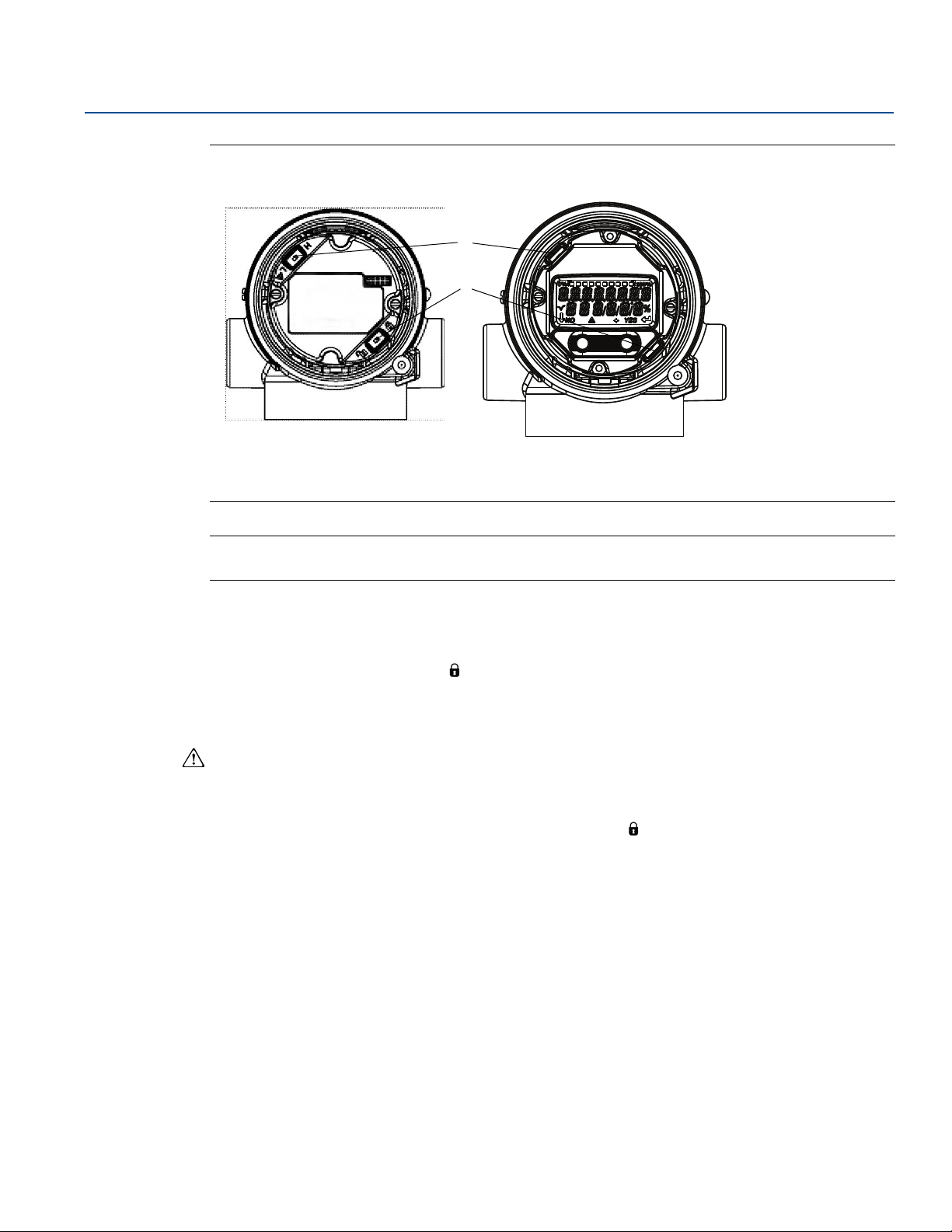
Reference Manual
A
B
00809-0100-4107, Rev CA
Figure 4-2. 4—20 mA Electronics Board
A. Alarm
B. Security
Electrical Installation
July 2017
without LCD meter with LCD display
Note
1-5 Vdc Alarm and Security switches are located in the same location as 4-20 mA output boards.
4.4.1 Security switch
The security switch is used to prevent changes to the transmitter configuration data. If the security
switch is set to the locked location ( ), any transmitter configuration requests sent via HART, LOI, or
local configuration buttons will be rejected by the transmitter and the transmitter configuration data will
not be modified. See figure above for the location of the security switch. Follow the steps below to
enable the security switch.
1. Set loop to manual and remove power.
2. Remove transmitter housing cover.
3. Use a small screwdriver to slide the switch to the lock ( ) position.
4. Replace transmitter housing cover; cover must be fully engaged to comply with explosion proof
requirements.
4.4.2 HART Lock
The HART Lock prevents changes to the transmitter configuration from all sources; all changes requested
via HART, LOI, and local configuration buttons will be rejected. The HART Lock can only be set via HART
communication, and is only available in HART Revision 7 mode. The HART Lock can be enabled or
disabled with a Field Communicator or AMS Device Manager.
Electrical Installation
51
Page 62

Electrical Installation
July 2017
Configuring HART Lock using Field Communicator
From the HOME screen, enter the fast key sequence
Reference Manual
00809-0100-4107, Rev CA
Device Dashboard Fast Keys
Configuring HART Lock using AMS device Manager
1. Right click on the device and select Configure.
2. Under Manual Setup select the Security tab.
3. Select Lock/Unlock button under HART Lock (Software) and follow the screen prompts.
4.4.3 Configuration button lock
The configuration button lock disables all local button functionality. Changes to the transmitter
configuration from the LOI and local buttons will be rejected. Local external keys can be locked via HART
communication only.
Configuring configuration button lock using a Field Communicator
From the HOME screen, enter the fast key sequence
Device Dashboard Fast Keys
Configuring configuration button lock using AMS device Manager
1. Right click on the device and select Configure.
2, 2, 6, 4
2, 2, 6, 3
2. Under Manual Setup select the Security tab.
3. Within the Configuration Buttons dropdown menu select Disabled to lock external local keys.
4. Select Send.
5. Confirm service reason and select Yes .
52
Electrical Installation
Page 63

Reference Manual
EXTENDED MENU
CALIBRAT
DAMPING
TRANSFER FUNCT
SCALED VARIAB
ASSIGN P
TAG
ALARM SAT VALUES
PASSWORD
PASSWORD
SIMULATE
HART REV
BACK TO MENU
EXIT MENU
PASSWORD
PASSWORD ENABLE
CHANGE PASSWORD
BACK TO MENU
EXIT MENU
VIEW CONFIG
ZERO TRIM
UNITS
RERANGE
LOOP TEST
DISPLAY
EXTENDED MENU
EXTENDED MENU
EXIT MENU
00809-0100-4107, Rev CA
4.4.4 LOI password
A Local Operator Interface Password can be entered and enabled to prevent review and modification of
device configuration via the LOI. This does not prevent configuration from HART or external keys (analog
zero and span; Digital Zero Trim). The LOI password is a 4 digit code that is to be set by the user. If the
password is lost or forgotten the master password is “9307”.
The LOI password can be configured and enabled/disabled by HART Communication via a Field
Communicator, AMS Device Manager, or the LOI.
Configuring LOI password with Field Communicator
From the HOME screen, enter the Fast Key sequence
Electrical Installation
July 2017
Device Dashboard Fast Keys
2, 2, 6, 5, 2
Configuring LOI password with AMS Device Manager
1. Right click on the device and select Configure.
2. Under Manual Setup select the Security tab.
3. Within the Local Operator Interface select the Configure Password button and follow the screen
prompts.
Configuring LOI password using LOI
Figure 4-3. Local Operator Interface password
4.5 Setting transmitter alarm
Electrical Installation
On the electronics board is an alarm switch, reference Figure 4-2 on page 51 for switch location. Follow
the steps below to change the alarm switch location:
1. Set loop to manual and remove power.
2. Remove transmitter housing cover.
3. Use a small screwdriver to slide switch to desired position.
4. Replace transmitter cover; cover must be fully engaged to comply with explosion proof requirements.
53
Page 64

Electrical Installation
A
B
A
B
A
July 2017
4.6 Electrical considerations
Note
Make sure all electrical installation is in accordance with national and local code requirements.
Do not run signal wiring in conduit or open trays with power wiring or near heavy electrical equipment.
4.6.1 Conduit installation
Recommended conduit connections are shown in Figure 4-4.
If all connections are not sealed, excess moisture accumulation can damage the transmitter. Make sure
to mount the transmitter with the electrical housing positioned downward for drainage. To avoid
moisture accumulation in the housing, install wiring with a drip loop, and ensure the bottom of the drip
loop is mounted lower than the conduit connections or the transmitter housing.
Reference Manual
00809-0100-4107, Rev CA
Figure 4-4. Conduit Installation
Correct Correct Incorrect
A. Possible conduit line positions
B. Sealing compound
4.6.2 Power supply
4—20 mA HART (option code A)
Transmitter operates on 10.5—42.4 Vdc at the terminal of the transmitter. The DC power supply should
provide power with less than two percent ripple. A minimum of 16.6 V is required for loops with a 250
resistance.
Note
A minimum loop resistance of 250 is required to communicate with a Field Communicator. If a single
power supply is used to power more than one Rosemount 2051 Transmitter, the power supply used, and
circuitry common to the transmitters, should not have more that 20 of impedance at 1200 Hz.
54
Electrical Installation
Page 65

Reference Manual
10.52030
1387
1000
500
0
Operating
region
Load (Ωs)
A
B
00809-0100-4107, Rev CA
Figure 4-5. Load Limitation
The Field Communicator requires a minimum loop resistance of 250 for communication.
Electrical Installation
July 2017
Maximum loop resistance = 43.5 x (power supply voltage — 10.5)
The total resistance load is the sum of the resistance of the signal leads and the load resistance of the
controller, indicator, I.S. Barriers, and related pieces. If intrinsic safety barriers are used, the resistance
and voltage drop must be included.
1—5 Vdc low power HART (output code M)
Low power transmitters operate on 9—28 Vdc. The DC power supply should provide power with less than
2 percent ripple. The V
load should be 100 k or greater.
out
4.6.3 Wiring the transmitter
Do not connect the power signal wiring to the test terminals. Incorrect wiring can damage test
circuit.
Note
Use shielded twisted pairs to yield best results. To ensure proper communication, use 24 AWG or larger
wire and do not exceed 5000 ft. (1500 m). For 1—5 V 500 ft. (150 m) maximum are recommended.
unpaired three conductor or two twisted pairs is recommended.
Voltage (Vdc)
42.4
Electrical Installation
Figure 4-6. Wiring the Transmitter (4—20 mA HART)
A. DC power supply
250 (necessary for HART Communication only)
B. R
L
55
Page 66

Electrical Installation
A
B
July 2017
Figure 4-7. Wiring the Transmitter (1—5 Vdc Low Power)
A. DC power supply
B. Voltmeter
Perform the following procedure to make wiring connections:
1. Remove the housing cover on terminal compartment side. Do not remove the cover in explosive
Reference Manual
00809-0100-4107, Rev CA
atmospheres when the circuit is live. Signal wiring supplies all power to the transmitter.
2. For 4—20 mA HART Output, connect the positive lead to the terminal marked (pwr/comm+) and
the negative lead to the terminal marked (pwr/comm—). Do not connect the powered signal
wiring to the test terminals. Power could damage the test diode.
a. For 1—5 Vdc HART Output, connect the positive lead to (PWR +) and the negative to the
(PWR—). Do not connect the powered signal wiring to the test terminals. Power could damage
the test diode.
3. Plug and seal unused conduit connection on the transmitter housing to avoid moisture
accumulation in the terminal side.
4.6.4 Grounding the transmitter
Signal cable shield grounding
Signal cable shield grounding is summarized in Figure 4-8 on page 57. The signal cable shield and unused
shield drain wire must be trimmed and insulated, ensuring that the signal cable shield and drain wire do
not come in contact with the transmitter case. See “Transmitter case grounding” on page 57 for
instructions on grounding the transmitter case. Follow the steps below to correctly ground the signal
cable shield.
1. Remove the field terminals housing cover.
2. Connect the signal wire pair at the field terminals as indicated in Figure 4-6.
56
3. At the field terminals, the cable shield and shield drain wire should be trimmed close and
insulated from transmitter housing.
4. Reattach the field terminals housing cover; cover must be fully engaged to comply with
explosion proof requirements.
5. At terminations outside the transmitter housing, the cable shield drain wire should be
continuously connected.
Electrical Installation
Page 67

Reference Manual
00809-0100-4107, Rev CA
a. Prior to the termination point, any exposed shield drain wire should be insulated as shown in
6. Properly terminate the signal cable shield drain wire to an earth ground at or near the power
Figure 4-8. Wiring Pair and Ground
Electrical Installation
July 2017
Figure 4-8 (B).
supply.
A
DP
C
A. Insulate Shield and shield drain wire
B. Insulate exposed shield drain wire
C. Terminate cable shield drain wire to earth ground
B
Transmitter case grounding
Always ground the transmitter case in accordance with national and local electrical codes. The most
effective transmitter case grounding method is a direct connection to earth ground with minimal
impedance. Methods for grounding the transmitter case include:
Internal ground connection: The internal ground connection screw is inside the FIELD
TERMINALS side of the electronics housing. This screw is identified by a ground symbol ( ).
The ground connection screw is standard on all Rosemount 2051 Transmitters. Refer to Figure
4-9 on page 58.
External ground connection: The external ground connection is located on the exterior of the
transmitter housing. Refer to Figure 4-10 on page 58. This connection is only available with
option V5 and T1.
Electrical Installation
57
Page 68

Electrical Installation
A
July 2017
Figure 4-9. Internal Ground Connection
A. Internal ground location
Figure 4-10. External Ground Connection (Option V5 or T1)
Reference Manual
00809-0100-4107, Rev CA
A
A. External ground location
Note
Grounding the transmitter case via threaded conduit connection may not provide sufficient ground
continuity.
Transient protection terminal block grounding
The transmitter can withstand electrical transients of the energy level usually encountered in static
discharges or induced switching transients. However, high-energy transients, such as those induced in
wiring from nearby lightning strikes, can damage the transmitter.
The transient protection terminal block can be ordered as an installed option (code T1) or as a spare part
to retrofit existing Rosemount 2051 Transmitters in the field. See “Spare parts” on page 145 for part
numbers. The lightning bolt symbol shown in Figure 4-11 on page 59 identifies the transient protection
terminal block.
58
Electrical Installation
Page 69

Reference Manual
00809-0100-4107, Rev CA
Figure 4-11. Transient Protection Terminal Block
A. Lightning bolt location
Electrical Installation
July 2017
A
Note
The transient protection terminal block does not provide transient protection unless the transmitter
case is properly grounded. Use the guidelines to ground the transmitter case. Refer to Figure 4-11.
Electrical Installation
59
Page 70

Electrical Installation
July 2017
Reference Manual
00809-0100-4107, Rev CA
60
Electrical Installation
Page 71

Reference Manual
00809-0100-4107, Rev CA
Operation and Maintenance
Section 5 Operation and Maintenance
Overview . . . . . . . . . . . . . . . . . . . . . . . . . . . . . . . . . . . . . . . . . . . . . . . . . . . . . . . . . . . . . . . . . . . . . . . . . . . . page 61
Safety messages . . . . . . . . . . . . . . . . . . . . . . . . . . . . . . . . . . . . . . . . . . . . . . . . . . . . . . . . . . . . . . . . . . . . . . page 61
Recommended calibration tasks . . . . . . . . . . . . . . . . . . . . . . . . . . . . . . . . . . . . . . . . . . . . . . . . . . . . . . . . page 62
Calibration overview . . . . . . . . . . . . . . . . . . . . . . . . . . . . . . . . . . . . . . . . . . . . . . . . . . . . . . . . . . . . . . . . . . page 62
Trim the pressure signal . . . . . . . . . . . . . . . . . . . . . . . . . . . . . . . . . . . . . . . . . . . . . . . . . . . . . . . . . . . . . . . page 66
Trim the analog output . . . . . . . . . . . . . . . . . . . . . . . . . . . . . . . . . . . . . . . . . . . . . . . . . . . . . . . . . . . . . . . .page 69
Switching HART Revision . . . . . . . . . . . . . . . . . . . . . . . . . . . . . . . . . . . . . . . . . . . . . . . . . . . . . . . . . . . . . . page 72
5.1 Overview
This section contains information on calibrating Rosemount™ 2051 Pressure Transmitters.
Field Communicator, AMS
perform configuration functions.
™
, Device Manager and Local Operator Interface (LOI) instructions are given to
July 2017
5.2 Safety messages
Procedures and instructions in this section may require special precautions to ensure the safety of the
personnel performing the operations. Information that raises potential safety issues is indicated by a
warning symbol ( ). Refer to the following safety messages before performing an operation preceded
by this symbol.
Explosions could result in death or serious injury.
Installation of this transmitter in an explosive environment must be in accordance with the
appropriate local, national, and international standards, codes, and practices. Review the approvals
section of the Rosemount 2051 reference manual for any restrictions associated with a safe
installation.
Before connecting a Field Communicator in an explosive atmosphere, ensure the instruments in
the loop are installed in accordance with intrinsically safe or non-incendive field wiring practices.
In an Explosion-proof/flameproof installation, do not remove the transmitter covers when power
is applied to the unit.
Process leaks may cause harm or result in death.
Install and tighten process connectors before applying pressure.
Electrical shock can result in death or serious injury.
Avoid contact with the leads and terminals. High voltage that may be present on leads can cause
electrical shock.
Operation and Maintenance
61
Page 72

Operation and Maintenance
July 2017
5.3 Recommended calibration tasks
Absolute pressure transmitters (Rosemount 2051CA and 2051TA) are calibrated at the factory.
Trimming adjusts the position of the factory characterization curve. It is possible to degrade
performance of the transmitter if any trim is done improperly or with inaccurate equipment.
Table 5-1. Basic and Full Calibration Tasks
Field installation tasks Bench calibration tasks
Reference Manual
00809-0100-4107, Rev CA
1. Perform sensor zero/lower trim: Compensate for
mounting pressure effects.
a. Refer to Rosemount 305, 306, and 304 Manifolds for
operation instructions to properly drain/vent valves
2. Set/check basic configuration parameters.
a. Output units
b. Range points
c. Output type
d. Damping Value
Note
For Rosemount 2051CA, 2051TA range 0 and range 5 devices, an accurate absolute pressure source is
required.
5.4 Calibration overview
The Rosemount 2051 Transmitter is an accurate instrument that is fully calibrated in the factory. Field
calibration is provided to the user to meet plant requirements or industry standards. Complete
calibration of the transmitter can be split into two halves: sensor calibration and analog output
calibration.
Sensor calibration allows the user to adjust the pressure (digital value) reported by the transmitter to be
equal to a pressure standard. The sensor calibration can adjust the pressure offset to correct for
mounting conditions or line pressure effects. This correction is recommended. The calibration of the
pressure range (pressure span or gain correction) requires accurate pressure standards (sources) to
provide a full calibration.
1. Perform optional 4—20 mA 1—5 Vdc output trim.
2. Perform a sensor trim.
a. Zero/lower trim using line pressure effect
correction. Reference Rosemount 305, 306,
and 304 Manifolds for drain/vent valve
operation instructions.
b. Optional full scale trim. Sets the span of the
device and requires accurate calibration
equipment.
c. Set/check basic configuration parameters.
62
Like the sensor calibration, the analog output can be calibrated to match the user measurement system.
The analog output trim (4—20 mA/1—5 V output trim) will calibrate the loop at the 4 mA (1 V) and 20 mA
(5 V) points.
The sensor calibration and the analog output calibration combine to match the transmitter’s
measurement system to the plant standard.
Calibrate the sensor
Sensor trim (page 67)
Zero trim (page 67)
Operation and Maintenance
Page 73

Reference Manual
00809-0100-4107, Rev CA
Calibrate the 4—20 mA output
4—20 mA/1—5 V output trim (page 70)
4—20 mA/1—5V output trim using other scale (page 71)
5.4.1 Determining necessary sensor trims
Bench calibrations allow for calibrating the instrument for its desired range of operation. Straight
forward connections to pressure source allow for a full calibration at the planned operating points.
Exercising the Transmitter over the desired pressure range allows for verification of the analog output.
“Trim the pressure signal” on page 66 discusses how the trim operations change the calibration. It is
possible to degrade the performance of the transmitter if a trim is done improperly or with inaccurate
equipment. The transmitter can be set back to factory settings using the recall factory trim command in
“Recall factory trim–sensor trim” on page 68.
For transmitters that are field installed, the manifolds discussed in Section 3: Rosemount 305, 306, and
304 Manifolds allow the differential transmitter to be zeroed using the zero trim function. Both 3-valve
and 5-valve manifolds are discussed. This field calibration will eliminate any pressure offsets caused by
mounting effects (head effect of the oil fill) and static pressure effects of the process.
Determine the necessary trims with the following steps:
Operation and Maintenance
July 2017
1. Apply pressure
2. Check digital pressure, if the digital pressure does not match the applied pressure, perform a digital
trim. See “Perform a sensor trim” on page 67.
3. Check reported analog output against the live analog output. If they do not match, perform an
analog output trim. See “Performing digital-to-analog trim (4—20 mA/1—5 V output trim)” on
page 70.
Trimming with configuration buttons
Local configuration buttons are external buttons located underneath the top tag of the transmitter.
There are two possible sets of local configuration buttons that can be ordered and used to perform trim
operations: Digital zero trim and LOI. To access the buttons, loosen screw and rotate top tag until
buttons are visible.
LOI (M4): Can perform both digital sensor trim and the 4—20mA output trim (analog output trim).
Follow the same procedures listed in trimming with Field Communicator or AMS Device Manager listed
below.
Digital zero trim (DZ): Used for performing a sensor zero trim. See “Determining calibration
frequency” on page 64 for trim instructions.
All configuration changes should be monitored by a display or by measuring the loop output.
shows the physical differences between the two sets of buttons.
Figure 5-1. Local Configuration Button Options
LOI–green retainer Digital zero trim–blue retainer
Figure 5-1
Operation and Maintenance
63
Page 74

Operation and Maintenance
(Reference accuracy)2(Temperature effe ct)2(Static pressure effect)
2
++
0.025 U RL
Span
----------------------------- --------- 0 . 1 2 5+
% per 50 °F 0.167% of span=
0.1% reading per 1000 psi (69 bar) 0.05 % of span at maximum span=
Stability
0.100 URL
Span
----------------------------- ---------
% of span for 2 years 0.0069 % of URL for 1 month==
Cal. Freq.
Req. Performance TPE–
Stability per Month
------------------------------ ------------- ------------- ---------- --
0.3% 0.189 %–
0.0069%
------------------------------ -------------- 1 6 xmonths===
July 2017
5.4.2 Determining calibration frequency
Calibration frequency can vary greatly depending on the application, performance requirements, and
process conditions. Use the following procedure to determine calibration frequency that meets the
needs of your application:
1. Determine the performance required for your application.
2. Determine the operating conditions.
3. Calculate the Total Probable Error (TPE).
4. Calculate the stability per month.
5. Calculate the calibration frequency.
Sample calculation for Rosemount 2051
Step 1: Determine the performance required for your application.
Required Performance: 0.30% of span
Step 2: Determine the operating conditions.
Reference Manual
00809-0100-4107, Rev CA
Transmitter: Rosemount 2051CD, range 2 (URL=250 inH2O[623 mbar])
Calibrated span: 150 inH
Ambient temperature change: ± 50 °F (28 °C)
Line pressure: 500 psig (34,5 bar)
O (374 mbar)
2
Step 3: Calculate TPE.
TPE = = 0.189% of span
Where:
Reference accuracy = ± 0.065% of span
Ambient temperature effect =
(1)
Span static pressure effect
1. Zero static pressure effect removed by zero trimming at line pressure.
=
Step 4: Calculate the stability per month.
Step 5: Calculate calibration frequency.
Sample calculation for Rosemount 2051C with P8 option
(0.05% accuracy and 5-year stability)
Step 1: Determine the performance required for your application.
Required performance: 0.30% of span
64
Operation and Maintenance
Page 75

Reference Manual
(Reference accuracy)2(Temperature effe ct)2(Static pressure effect)
2
++
0.025 U RL
Span
----------------------------- --------- 0 . 1 2 5+
% per 50 °F 0.0833% of span=
0.1% reading per 1000 psi (69 bar) 0.05 % of span at maximum span=
Stability
0.125 U RL
Span
----------------------------- ---------
% of span for 5 years 0.0035 % of URL for 1 month==
Cal. Freq.
Req. Performance TPE–
Stability per Month
------------------------------- ------------- ------------- -----------
0.3% 0.117%–
0.0035%
------------------------------- ------------- 5 2 m o n t h s===
00809-0100-4107, Rev CA
Step 2: Determine the operating conditions.
Transmitter: Rosemount 2051CD, range 2 (URL=250 inH2[623 mbar])
Calibrated span: 150 inH
Ambient temperature change: ±50 °F (28 °C)
Line pressure: 500 psig (34,5 bar)
Step 3: Calculate TPE.
O (374 mbar)
2
Operation and Maintenance
July 2017
TPE =
Where:
Reference accuracy = ± 0.05% of span
Ambient temperature effect =
(1)
Span static pressure effect
1. Zero static pressure effect removed by zero trimming at line pressure.
=
= 0.117% of span
Step 4: Calculate the stability per month.
Step 5: Calculate calibration frequency.
5.4.3 Compensating for span line pressure effects
(range 4 and range 5)
Rosemount 2051 Range 4 and 5 Pressure Transmitters require a special calibration procedure when used
in differential pressure applications. The purpose of this procedure is to optimize transmitter
performance by reducing the effect of static line pressure in these applications. The transmitters (ranges
0 through 3) do not require this procedure because optimization occurs at the sensor.
The systematic span shift caused by the application of static line pressure is —0.95 percent of reading per
1000 psi (69 bar) for range 4 transmitters, and —1 percent of reading per 1000psi (69 bar) for range 5
transmitters. Using the following procedure, the span effect can be corrected to ±0.2 percent of reading
per 1000 psi (69 bar) for line pressures from 0 to 3626 psi (0 to 250 bar).
Use the following example to compute correct input values.
Example
A range 4 differential pressure HART® transmitter (Rosemount 2051CD4...) will be used in an application
with a static line pressure of 1200 psi (83 bar). The transmitter output is ranged with 4 mA at 500 inH
(1, 2 bar) and 20 mA at 1500 inH
pressure, first use the following formulas to determine the corrected values for the high trim value.
Operation and Maintenance
O
2
O (3, 7 bar). To correct for systematic error caused by high static line
2
65
Page 76

Operation and Maintenance
July 2017
High Trim Value:
HT = (URV — [S/100 x P/1000 x LRV])
Reference Manual
00809-0100-4107, Rev CA
HT = Corrected High Trim Value
Where:
In this example:
URV = Upper Range Value
S = Span shift per specification (as a percent of reading)
P = Static Line Pressure in psi
URV = 1500 inH
S = —0.95%
P = 1200 psi
LT = 1500 — (—0.95%/100 x 1200 psi/1000 psi x 1500 inH
LT = 1517.1 inH
O (3.74 bar)
2
O
2
O)
2
Complete the upper sensor trim procedure as described in “Perform a sensor trim” on page 67. In the
example above, at step 4, apply the nominal pressure value of 1500 inH
calculated correct upper sensor trim value of 1517.1 inH
O with a Field Communicator.
2
O. However, enter the
2
Note
The range values for the 4 and 20 mA points should be at the nominal URV and LRV. In the example
above, the values are 1500 inH
O and 500 inH2O respectively. Confirm the values on the HOME screen of
2
the Field Communicator. Modify, Safety Instrumented Systems Requirements, by following the steps in
“Rerange the transmitter” on page 15.
5.5 Trim the pressure signal
5.5.1 Sensor trim overview
A sensor trim corrects the pressure offset and pressure range to match a pressure standard. The upper
sensor trim corrects the pressure range and the lower sensor trim (zero trim) corrects the pressure
offset. an accurate pressure standard is required for full calibration. a zero trim can be performed if the
process is vented, or the high and low side pressure are equal (for differential pressure transmitters).
Zero trim is a single-point offset adjustment. It is useful for compensating for mounting position effects
and is most effective when performed with the transmitter installed in its final mounting position. Since
this correction maintains the slope of the characterization curve, it should not be used in place of a
Sensor Trim over the full sensor range.
When performing a zero trim, ensure that the equalizing valve is open and all wet legs are filled to the
correct levels. Line pressure should be applied to the transmitter during a zero trim to eliminate line
pressure errors. Refer to Section 3: Manifold operation.
Note
Do not perform a zero trim on Rosemount 2051T Absolute Pressure Transmitters. Zero trim is zero
based, and absolute pressure transmitters reference absolute zero. To correct mounting position effects
on a transmitter, perform a low trim within the sensor trim function. The low trim function provides an
offset correction similar to the zero trim function, but it does not require zero-based input.
66
Operation and Maintenance
Page 77

Reference Manual
A
B
B
A
00809-0100-4107, Rev CA
Upper and lower sensor trim is a two-point sensor calibration where two end-point pressures are
applied, all output is linearized between them, and requires an accurate pressure source. Always adjust
the low trim value first to establish the correct offset. Adjustment of the high trim value provides a slope
correction to the characterization curve based on the low trim value. The trim values help optimize
performance over a specific measurement range.
Figure 5-2. Sensor Trim Example
Operation and Maintenance
July 2017
A. Before trim
B. After trim
5.5.2 Perform a sensor trim
When performing a sensor trim, but the upper and lower limits can be trimmed. If both upper and lower
trims are to be performed, the lower trim must be done prior to the upper time.
Note
Use a pressure input source that is at least four times more accurate than the transmitter, and allow the
input pressure to stabilize for 10 seconds before entering any values.
Performing a sensor trim with a Field Communicator
From the HOME screen, enter the Fast Key sequence and follow the steps within the Field Communicator
to complete the Sensor Trim.
Device Dashboard Fast Keys
To calibrate the sensor with a Field Communicator using the sensor trim function, perform the following
procedure:
1. Select Lower Sensor Trim.
3, 4, 1
Note
Select pressure points so that lower and upper values are equal to or outside the expected process
operation range. This can be done by going to “Rerange the transmitter” on page 15 of Section 2:
Configuration.
Operation and Maintenance
67
Page 78

Operation and Maintenance
EXTENDED MENU
CALIBRAT
CALIBRAT
DAMPING
TRANSFER FUNCT
SCALED VARIAB
ASSIGN PV
TAG
ALARM SAT VALUES
PASSWORD
SIMULATE
HART REV
BACK TO MENU
EXIT MENU
VIEW CONFIG
ZERO TRIM
UNITS
RERANGE
LOOP TEST
DISPLAY
EXTENDED MENU
EXTENDED MENU
EXIT MENU
CALIBRAT
ZERO TRIM
LOWER TRIM
LOWER TRIM
UPPER TRIMUPPER TRIM
ANALOG TRIM
FACTORY RECALL
BACK TO MENU
EXIT MENU
July 2017
2. Follow the commands provided by the Field Communicator to complete the adjustment of the lower
value.
3. Repeat the procedure for the upper value, replacing 2: Lower Sensor Trim with 3: Upper Sensor Trim in
Step 1.
Performing a sensor trim with AMS Device Manager
Right click on the device and, under the Method dropdown menu, move cursor over Calibrate and, under
Sensor Trim, select Lower Sensor Trim.
1. Follow the screen prompts to perform a Sensor Trim using AMS Device Manager.
2. If desired, right click on the device and under the Method dropdown menu, move cursor over Calibrate
and under Sensor Trim and select Upper Sensor Trim
Performing a sensor trim using LOI
Perform an upper and lower sensor trim by referencing Figure 5-3.
Figure 5-3. Sensor Trim with LOI
Reference Manual
00809-0100-4107, Rev CA
5.5.3 Recall factory trim–sensor trim
68
Performing a digital zero trim (option DZ)
A digital zero trim (option DZ) provides the same function as a zero/lower sensor trim, but can be
completed in hazardous areas at any given time by simply pushing the zero trim button when the
transmitter is at zero pressure. If the transmitter is not close enough to zero when the button is pushed,
the command may fail due to excess correction. If ordered, a digital zero Trim can be performed by
utilizing external configuration buttons located underneath the top tag of the transmitter, see Figure 5-1
on page 63 for DZ button location.
1. Loosen the top tag of the transmitter to expose buttons.
2. Press and hold the digital zero button for at least two seconds, then release to perform a digital zero
trim.
The recall factory trim–sensor trim command allows the restoration of the as-shipped factory settings
of the sensor trim. This command can be useful for recovering from an inadvertent zero trim of an
absolute pressure unit or inaccurate pressure source.
Operation and Maintenance
Page 79

Reference Manual
EXTENDED MENU
CALIBRAT
CALIBRAT
DAMPING
TRANSFER FUNCT
SCALED VARIAB
ASSIGN PV
TAG
ALARM SAT VALUES
PASSWORD
SIMULATE
HART REV
BACK TO MENU
EXIT MENU
VIEW CONFIG
ZERO TRIM
UNITS
RERANGE
LOOP TEST
DISPLAY
EXTENDED MENU
EXTENDED MENU
EXIT MENU
CALIBRAT
ZERO TRIM
LOWER TRIM
UPPER TRIM
ANALOG TRIM
FACTORY RECALL
FACTORY RECALL
BACK TO MENU
EXIT MENU
FACTORY RECALL
SENSOR RECALL
SENSOR RECALL
ANALOG RECALL
BACK TO MENU
EXIT MENU
00809-0100-4107, Rev CA
Recalling factory trim with a Field Communicator
From the HOME screen, enter the Fast Key sequence and follow the steps within the Field Communicator
to complete the sensor trim.
Operation and Maintenance
July 2017
Device Dashboard Fast Keys
3, 4, 3
Recalling factory trim with AMS Device Manager
Right click on the device and, under the Method dropdown menu, move cursor over Calibrate and select
Restore Factory Calibration.
1. Select Next after setting the control loop to manual.
2. Select Sensor Trim under Trim to recall and select Next.
3. Follow the screen prompts to recall sensor trim.
Recalling factory trim - sensor trim using LOI
Refer to Figure 5-4 to recall factory sensor trim.
Figure 5-4. Recall Factory Trim - Sensor Trim with LOI
5.6 Trim the analog output
Operation and Maintenance
The analog output trim commands allow you to adjust the transmitter’s current output at the 4 and
20 mA points to match the plant standards. This trim is performed after the digital to analog conversion
so only the 4—20mA analog signal will be affected.
Figure 5-5 graphically shows the two ways the
characterization curve is affected when an analog output trim is performed.
69
Page 80

Operation and Maintenance
A
A
B
B
mA Output
mA Output
July 2017
Figure 5-5. Analog Output Trim Example
A. Before trim
B. After Trim
Reference Manual
00809-0100-4107, Rev CA
5.6.1 Performing digital-to-analog trim (4—20 mA/1—5 V output trim)
Note
If a resistor is added to the loop, ensure that the power supply is sufficient to power the transmitter to a
20 mA output with additional loop resistance. Refer to “Power supply” on page 54.
Performing a 4—20 mA/1—5 V output trim with a Field Communicator
From the HOME screen, enter the Fast Key sequence and follow the steps within the Field Communicator
to complete the 4—20 mA output trim.
Device Dashboard Fast Keys
3, 4, 2, 1
Performing a 4—20 mA/1—5 V output trim with AMS Device Manager
Right click on the device and, under the Method drop down menu, move cursor over Calibrate and select
Analog Calibration.
1. Select Digital to Analog Trim.
2. Follow the screen prompts to perform a 4—20 mA output trim.
70
Operation and Maintenance
Page 81

Reference Manual
EXTENDED MENU
CALIBRAT
CALIBRAT
DAMPING
TRANSFER FUNCT
SCALED VARIAB
ASSIGN PV
TAG
ALARM SAT VALUES
PASSWORD
SIMULATE
HART REV
BACK TO MENU
EXIT MENU
VIEW CONFIG
ZERO TRIM
UNITS
RERANGE
LOOP TEST
DISPLAY
EXTENDED MENU
EXTENDED MENU
EXIT MENU
CALIBRAT
ZERO TRIM
LOWER TRIM
UPPER TRIM
ANALOG TRIM
ANALOG TRIM
FACTORY RECALL
BACK TO MENU
EXIT MENU
00809-0100-4107, Rev CA
Performing 4—20mA/1—5 V output trim using LOI
Figure 5-6. 4—20mA Output Trim Using LOI
Operation and Maintenance
July 2017
5.6.2 Performing digital-to-analog trim (4—20mA/1—5 V output trim)
5.6.3 Recalling factory trim–analog output
Operation and Maintenance
using other scale
The Scaled 4—20 mA output Trim command matches the 4 and 20 mA points to a user selectable
reference scale other than 4 and 20 mA (for example, 2 to 10 volts if measuring across a 500 load, or 0
to 100 percent if measuring from a Distributed Control System [DCS]). To perform a scaled 4—20 mA
output trim, connect an accurate reference meter to the transmitter and trim the output signal to scale,
as outlined in the output trim procedure.
Performing a 4—20/ 1—5 V mA output trim using other scale with a
Field Communicator
From the HOME screen, enter the Fast Key sequence and follow the steps within the Field Communicator
to complete the 4—20 mA output trim using other scale.
Device Dashboard Fast Keys
Performing a 4—20 mA/1—5 V output trim using other scale with AMS
Device Manager
Right click on the device and under the Method dropdown menu, move cursor over Calibrate and select
Analog Calibration.
1. Select Scaled Digital to Analog Trim.
2. Follow screen prompts to perform a 4—20 mA/1—5 V output trim.
The recall factory trim–analog output command allows the restoration of the as-shipped factory
settings of the analog output trim. This command can be useful for recovering from an inadvertent trim,
incorrect plant standard or faulty meter.
3, 4, 2, 2
71
Page 82

Operation and Maintenance
EXTENDED MENU
CALIBRAT
CALIBRAT
DAMPING
TRANSFER FUNCT
SCALED VARIAB
ASSIGN PV
TAG
ALARM SAT VALUES
PASSWORD
SIMULATE
HART REV
BACK TO MENU
EXIT MENU
VIEW CONFIG
ZERO TRIM
UNITS
RERANGE
LOOP TEST
DISPLAY
EXTENDED MENU
EXTENDED MENU
EXIT MENU
CALIBRAT
ZERO TRIM
LOWER TRIM
UPPER TRIM
ANALOG TRIM
FACTORY RECALL
FACTORY RECALL
BACK TO MENU
EXIT MENU
FACTORY RECALL
SENSOR RECALL
ANALOG RECALL
ANALOG RECALL
BACK TO MENU
EXIT MENU
July 2017
Recalling factory trim - analog output with a Field Communicator
From the HOME screen, enter the Fast Key sequence and follow the steps within the Field Communicator
to complete the digital to analog trim using other scale.
Reference Manual
00809-0100-4107, Rev CA
Device Dashboard Fast Keys
3, 4, 3
Recalling factory trim - analog output with AMS Device Manager
Right click on the device and, under the Method drop down menu, move cursor over Calibrate and select
Restore Factory Calibration.
1. Select Next to set the control loop to manual.
2. Select Analog Output Trim under Select trim to recall and select Next.
3. Follow screen prompts to recall analog output trim.
Recalling factory trim - analog output with LOI
Reference Figure 5-7 for LOI instructions.
Figure 5-7. Recall Factory Trim — analog output with LOI
5.7 Switching HART Revision
5.7.1 Switching HART Revision with generic menu
72
Some systems are not capable of communicating with HART Revision 7 devices. The following
procedures list how to change HART Protocol revisions between HART Revision 7 and HART Revision 5.
If the HART Protocol configuration tool is not capable of communicating with a HART Revision 7 device,
it should load a generic menu with limited capability. The following procedures allow for switching
between HART Revision 7 and HART Revision 5 from a generic menu.
1. Locate “Message” field
a. To change to HART Revision 5, Enter: HART5 in the message field
b. To change to HART Revision 7, Enter: HART7 in the message field
Operation and Maintenance
Page 83

Reference Manual
EXTENDED MENU
CALIBRAT
DAMPING
TRANSFER FUNCT
SCALED VARIAB
ASSIGN PV
TAG
ALARM SAT VALUES
PASSWORD
SIMULATE
HART REV
HART REV
BACK TO MENU
EXIT MENU
VIEW CONFIG
ZERO TRIM
UNITS
RERANGE
LOOP TEST
DISPLAY
EXTENDED MENU
EXTENDED MENU
EXIT MENU
00809-0100-4107, Rev CA
Operation and Maintenance
5.7.2 Switching HART Revision with Field Communicator
From the HOME screen, enter the Fast Key sequence and follow steps within the Field Communicator to
complete the HART revision change.
From the HOME screen, enter the Fast Key sequence HART5 HART7
Device Dashboard Fast Keys
2, 2, 5, 2, 4 2, 2, 5, 2, 3
5.7.3 Switching HART Revision with AMS Device Manager
1. Select on Manual Setup and select HART.
2. Select Change HART Revision then follow the on screen prompts.
Note
AMS Device Manager versions 10.5 or greater are compatible with HART Revision 7.
5.7.4 Switching HART Revision with LOI
July 2017
Navigate to HART REV within the extended menu and select if either HART REV 5 or HART REV 7. Use
Figure 5-8 below to change HART Revision:
Figure 5-8. Change HART Revision with LOI
Operation and Maintenance
73
Page 84

Operation and Maintenance
July 2017
Reference Manual
00809-0100-4107, Rev CA
74
Operation and Maintenance
Page 85

Reference Manual
00809-0100-4107, Rev CA
Section 6 Troubleshooting
Overview . . . . . . . . . . . . . . . . . . . . . . . . . . . . . . . . . . . . . . . . . . . . . . . . . . . . . . . . . . . . . . . . . . . . . . . . . . . . page 75
Safety messages . . . . . . . . . . . . . . . . . . . . . . . . . . . . . . . . . . . . . . . . . . . . . . . . . . . . . . . . . . . . . . . . . . . . . . page 75
Diagnostic messages . . . . . . . . . . . . . . . . . . . . . . . . . . . . . . . . . . . . . . . . . . . . . . . . . . . . . . . . . . . . . . . . . . page 77
Disassembly procedures . . . . . . . . . . . . . . . . . . . . . . . . . . . . . . . . . . . . . . . . . . . . . . . . . . . . . . . . . . . . . . . page 80
Reassembly procedures . . . . . . . . . . . . . . . . . . . . . . . . . . . . . . . . . . . . . . . . . . . . . . . . . . . . . . . . . . . . . . . page 81
6.1 Overview
Ta bl e 6 - 1 provides summarized maintenance and troubleshooting suggestions for the most common
operating problems.
If you suspect malfunction despite the absence of any diagnostic messages on the Field Communicator
display, consider using Section 6: Diagnostic messages on page 77 to identify any potential problem.
Troubleshooting
July 2017
6.2 Safety messages
Procedures and instructions in this section may require special precautions to ensure the safety of the
personnel performing the operations. Information that raises potential safety issues is indicated by a
warning symbol ( ). Refer to the following safety messages before performing an operation preceded
by this symbol.
Explosions could result in death or serious injury.
Installation of this transmitter in an explosive environment must be in accordance with the appropriate
local, national, and international standards, codes, and practices. Review the approvals section of the
Rosemount
Before connecting a Field Communicator in an explosive atmosphere, ensure the instruments in the
loop are installed in accordance with intrinsically safe or non-incendive field wiring practices.
In an Explosion-proof/flameproof installation, do not remove the transmitter covers when power is
applied to the unit.
Process leaks may cause harm or result in death.
Install and tighten process connectors before applying pressure.
Electrical shock can result in death or serious injury.
Avoid contact with the leads and terminals. High voltage that may be present on leads can cause
electrical shock.
™
2051 reference manual for any restrictions associated with a safe installation.
Troubleshooting
75
Page 86

Troubleshooting
July 2017
Table 6-1. Rosemount 2051 Troubleshooting Table for 4—20 mA Output
Symptom Corrective actions
Transmitter milliamp reading is zero Verify terminal voltage is 10.5 to 42.4 Vdc at signal terminals
Check power wires for reversed polarity
Check that power wires are connected to signal terminals
Check for open diode across test terminal
Transmitter Not Communicating with
Field Communicator
Transmitter milliamp reading is low or high Verify applied pressure
Verify terminal voltage is 10.5 to 42.4 Vdc
Check loop resistance, 250 minimum (PS voltage -transmitter voltage/loop
current)
Check that power wires are connected to signal terminals and not test terminals
Verify clean DC Power to transmitter (Max AC noise 0.2 volts peak to peak)
Verify the output is between 4 and 20 mA or saturation levels
Have Field Communicator poll for all addresses
00809-0100-4107, Rev CA
Reference Manual
Verify 4 and 20 mA range points
Verify output is not in alarm condition
Perform analog trim
Check that power wires are connected to the correct signal terminals (positive to
positive, negative to negative) and not the test terminal
Transmitter will not respond to changes in
applied pressure
Digital Pressure Variable reading is low or high Check impulse piping for blockage or low fill in wet leg
Digital Pressure Variable reading is erratic Check application for faulty equipment in pressure line
Milliamp reading is erratic Verify power source to transmitter has adequate voltage and current
Check impulse piping or manifold for blockage
Verify applied pressure is between the 4 and 20 mA points
Verify the output is not in alarm condition
Verify transmitter is not in loop test mode
Verify transmitter is not in multidrop mode
Check test equipment
Verify transmitter is calibrated properly
Check test equipment (verify accuracy)
Verify pressure calculations for application
Verify transmitter is not reacting directly to equipment turning on/off
Verify damping is set properly for application
76
Check for external electrical interference
Verify transmitter is properly grounded
Verify shield for twisted pair is only grounded at one end
Troubleshooting
Page 87

Reference Manual
00809-0100-4107, Rev CA
6.3 Diagnostic messages
Troubleshooting
July 2017
Listed in the below sections are detailed table of the possible messages that will appear on either the
LOI/LCD display, a Field Communicator, or an AMS
®
Device Manager system. Use the tables below to
diagnose particular status messages.
Good
Failed — fix now
Maintenance — fix soon
Advisory
6.3.1 Diagnostic message: Failed - fix now
Table 6-2. Status: Failed — Fix Now
Alert name LCD screen LOI screen Problem Recommended action
No Pressure
Updates
Electronics
Board Failure
Critical Sensor
Data Error
Critical
Electronics
Data Error
Sensor Failure FA IL
Incompatible
Electronics
and Sensor
NO P
UPDATE
FAI L
BOARD
MEMRY
ERROR
SENSOR
XMTR
MSMTCH
NO PRESS
UPDATE
FAI L
BOARD
MEMORY
ERROR
FAI L
SENSOR
XMTR
MSMTCH
There are no
pressure updates
from the sensor to
the electronics
A failure has been
detected in the
electronics circuit
board
A user written
parameter does not
match the expected
value
A user written
parameter does not
match the expected
value
A failure has been
detected in the
pressure sensor
The pressure sensor
is incompatible with
the attached
electronics
1. Ensure the sensor cable connection to the
electronics is tight.
2. Replace the pressure sensor.
1. Replace the electronics board.
1. Confirm and correct all parameters listed in Device
Information.
2. Perform a Device Reset.
3. Replace sensor module.
1. Confirm and correct all parameters listed in Device
Information.
2. Perform a Device Reset.
3. Replace electronics board.
1. Replace the pressure sensor.
1. Replace the electronics board or sensor with
compatible hardware.
Troubleshooting
77
Page 88

Troubleshooting
July 2017
6.3.2 Diagnostic message: Maintenance - fix soon
Table 6-3. Status: Maintenance — Fix Soon
Alert name LCD screen LOI screen Problem Recommended action
Reference Manual
00809-0100-4107, Rev CA
No
Tem pe ra tu re
Updates
Pressure Out of
Limits
Sensor
Tem pe ra tu re
Beyond Limits
Electronics
Tem pe ra tu re
Beyond Limits
Electronics
Board
Parameter Error
Configuration
Buttons
Operator Error
NO T
UPDATE
PRES
LIMITS
TEMP
LIMITS
MEMRY
WARN
(also in
advisory)
STUCK
BUTTON
NO TEMP
UPDATE
PRES OUT
LIMITS
TEMP OUT
LIMITS
MEMORY
WAR N
(also in
advisory)
STUCK
BUTTON
There are no
temperature updates
from the sensor to the
electronics
The pressure is either
above or below the
sensor limits
The sensor
temperature has
exceeded its safe
operating range
The temperature of the
electronics has
exceeded its safe
operating range.
A device parameter
does not match the
expected value. The
error does not affect
transmitter operation
or analog output.
Device is not
responding to button
presses.
1. Ensure the sensor cable connection to the electronics
is tight.
2. Replace the pressure sensor.
1. Check the transmitter pressure connection to ensure
it is not plugged or the isolating diaphragms are not
damaged.
2. Replace the pressure sensor.
1. Check the process and ambient conditions are within
—85 to 194 °F (—65 to 90 °C).
2. Replace the pressure sensor.
1. Confirm electronics temperature is within limits of —
85 to 194 °F (—65 to 90 °C).
2. Replace electronics board.
1. Replace the electronics board.
1. Check configuration buttons are not stuck.
2. Replace the electronics board.
78
Troubleshooting
Page 89

Reference Manual
00809-0100-4107, Rev CA
6.3.3 Diagnostic message: Advisory
Table 6-4. Status: Advisory
LCD
Alert name
Non-Critical
User Data
Warning
Sensor
Parameter
Warning
LCD Display
Update Failure
Configuration
Changed
Analog Output
Fixed
Simulation
Active
Analog Output
Saturated
screen
MEMRY
WAR N
[If display
is not
updating]
[none] [none]
ANLOG
FIXED
[none] [none]
ANLOG
SAT
LOI screen Problem Recommended action
MEMORY
WAR N
[If display
is not
updating]
ANALOG
FIXED
ANALOG
SAT
A user written parameter
does not match expected
value.
A user written parameter
does not match expected
value.
The LCD Display is not
receiving updates from the
pressure sensor.
A recent change has been
made the device by a
secondary HART master
such as a handheld device.
The analog output is fixed
and does not represent the
process measurement.
This may be caused by
other conditions in the
device, or because the
device has been set to loop
test or multidrop mode.
The device is in simulation
mode and may not be
reporting actual
information.
The analog output is
saturated either high or
low due to the pressure
either above or below the
range values.
Troubleshooting
July 2017
1. Confirm and correct all parameters listed in Device
Information.
2. Perform a Device Reset.
3. Replace Electronics Board.
1. Confirm and correct all parameters listed in Device
Information.
2. Perform a Device Reset.
3. Replace pressure sensor.
1. Check the connection between the LCD display and
the circuit board.
2. Replace the LCD display.
3. Replace the electronics board.
1. Verify that the configuration change of the device
was intended and expected.
2. Clear this alert by selecting Clear Configuration
Changed Status.
3. Connect a HART
Manager or similar which will automatically clear it.
1. Take action on any other notifications from the
device.
2. If the device is in loop test, and should no longer be,
disable or momentarily remove power.
3. If the device is in multidrop mode and should not be,
re-enable loop current by setting the polling address
to 0.
1. Verify that simulation is no longer required.
2. Disable simulation mode in service tools.
3. Perform a device reset.
1. Check the pressure applied to ensure it is between
the 4—20mA points.
2. Check the transmitter pressure connection to make
sure it is not plugged or isolating diaphragms are not
damaged.
3. Replace the pressure sensor.
®
master such as AMS Device
Troubleshooting
79
Page 90

Troubleshooting
July 2017
6.4 Disassembly procedures
Do not remove the instrument cover in explosive atmospheres when the circuit is live.
6.4.1 Removing from service
Follow these steps:
1. Follow all plant safety rules and procedures.
2. Power down device.
3. Isolate and vent the process from the transmitter before removing the transmitter from service.
4. Remove all electrical leads and disconnect conduit.
5. Remove the transmitter from the process connection.
a. The Rosemount 2051C Transmitter is attached to the process connection by four bolts and two
cap screws. Remove the bolts and screws and separate the transmitter from the process
connection. Leave the process connection in place and ready for re-installation. Reference
“Installation procedures” on page 30 for coplanar flange.
b. The Rosemount 2051T Transmitter is attached to the process by a single hex nut process
connection. Loosen the hex nut to separate the transmitter from the process. Do not wrench on
neck of transmitter. See warning in “In-line process connection” on page 38.
Reference Manual
00809-0100-4107, Rev CA
6. Do not scratch, puncture, or depress the isolating diaphragms.
7. Clean isolating diaphragms with a soft rag and a mild cleaning solution, and rinse with clear water.
8. For the Rosemount 2051C, whenever you remove the process flange or flange adapters, visually
inspect the PTFE O-rings. Replace the O-rings if they show any signs of damage, such as nicks or cuts.
Undamaged O-rings may be reused.
6.4.2 Removing terminal block
Electrical connections are located on the terminal block in the compartment labeled “FIELD
TERMINALS.”
1. Remove the housing cover from the field terminal side.
2. Loosen the two small screws located on the assembly in the 9 o’clock and 5 o’clock positions relative
to the top of the transmitter.
3. Pull the entire terminal block out to remove it.
6.4.3 Removing the electronics board
The transmitter electronics board is located in the compartment opposite the terminal side. To remove
the electronics board see Figure 4-2 on page 51 and perform following procedure:
1. Remove the housing cover opposite the field terminal side.
2. If you are disassembling a transmitter with a LOI/LCD display, loosen the two captive screws that are
visible (See Figure 4-1 on page 50 for screw locations). The two screws anchor the LOI/LCD display to
the electronics board and the electronics board to the housing.
80
Troubleshooting
Page 91

Reference Manual
00809-0100-4107, Rev CA
Note
The electronics board is electrostatically sensitive; observe handling precautions for static-sensitive
components
3. Using the two captive screws, slowly pull the electronics board out of the housing. The sensor module
ribbon cable holds the electronics board to the housing. Disengage the ribbon cable by pushing the
connector release.
Note
If an LOI/LCD display is installed, use caution as there is an electronic pin connector that interfaces
between the LOI/LCD display and electronics board.
Troubleshooting
6.4.4 Removing sensor module from the electronics housing
1. Remove the electronics board. Refer to “Removing the electronics board” on page 80.
Note
To prevent damage to the sensor module ribbon cable, disconnect it from the electronics board before
you remove the sensor module from the electrical housing.
July 2017
2. Carefully tuck the cable connector completely inside of the internal black cap.
Note
Do not remove the housing until after you tuck the cable connector completely inside of the internal
black cap. The black cap protects the ribbon cable from damage that can occur when you rotate the
housing.
5
3. Using a
4. Unscrew the module from the housing, making sure the black cap on the sensor module and sensor
cable do not catch on the housing.
/64-inch hex wrench, loosen the housing rotation set screw one full turn.
6.5 Reassembly procedures
1. Inspect all cover and housing (non-process wetted) O-rings and replace if necessary. Lightly grease
with silicone lubricant to ensure a good seal.
2. Carefully tuck the cable connector completely inside the internal black cap. To do so, turn the black
cap and cable counterclockwise one rotation to tighten the cable.
3. Lower the electronics housing onto the module. Guide the internal black cap and cable on the sensor
module through the housing and into the external black cap.
4. Turn the module clockwise into the housing.
Troubleshooting
81
Page 92

Troubleshooting
July 2017
Note
Make sure the sensor ribbon cable and internal black cap remain completely free of the housing as you
rotate it. Damage can occur to the cable if the internal black cap and ribbon cable become hung up and
rotate with the housing.
5. Thread the housing completely onto the sensor module. The housing must be no more than one full
turn from flush with the sensor module to comply with explosion proof requirements.
6. Tighten the housing rotation set screw using a
6.5.1 Attaching electronics board
1. Remove the cable connector from its position inside of the internal black cap and attach it to the
electronics board.
2. Using the two captive screws as handles, insert the electronics board into the housing. Make sure the
power posts from the electronics housing properly engage the receptacles on the electronics board.
Do not force. The electronics board should slide gently on the connections.
3. Tighten the captive mounting screws.
5
/64-in. hex wrench.
Reference Manual
00809-0100-4107, Rev CA
4. Replace the electronics housing cover. The transmitter covers must be engaged metal-to-metal to
ensure a proper seal and to meet explosion-proof requirements.
6.5.2 Installing terminal block
1. Gently slide the terminal block into place, making sure the two power posts from the electronics
housing properly engage the receptacles on the terminal block.
2. Tighten the captive screws.
3. Replace the electronics housing cover. The transmitter covers must be fully engaged to meet
explosion-proof requirements.
6.5.3 Reassembling the Rosemount 2051C Process Flange
1. Inspect the sensor module PTFE O-rings. Undamaged O-rings may be reused. Replace O-rings that
show any signs of damage, such as nicks, cuts, or general wear.
Note
If you are replacing the O-rings, be careful not to scratch the O-ring grooves or the surface of the
isolating diaphragm when removing the damaged O-rings.
82
Troubleshooting
Page 93

Reference Manual
00809-0100-4107, Rev CA
2. Install the process connection. Possible options include:
a. Coplanar process flange:
— Hold the process flange in place by installing the two alignment screws to finger tightness (screws
— Install the four 1.75-in. flange bolts by finger tightening them to the flange.
b. Coplanar process flange with flange adapters:
— Hold the process flange in place by installing the two alignment screws to finger tightness (screws
— Hold the flange adapters and adapter O-rings in place while installing (in the desired of the four
c. Manifold:
— Contact the manifold manufacturer for the appropriate bolts and procedures.
3. Tighten the bolts to the initial torque value using a crossed pattern. See Table 6-5 on page 83 for
appropriate torque values.
4. Using same cross pattern, tighten bolts to final torque values seen in Table 6-5 on page 83.
Troubleshooting
July 2017
are not pressure retaining). Do not overtighten as this will affect module-to-flange alignment.
are not pressure retaining). Do not overtighten as this will affect module-to-flange alignment.
possible process connection spacing configurations) using four 2.88-in. bolts to mount securely to
the coplanar flange. For gage pressure configurations, use two 2.88-in. bolts and two 1.75-in.
bolts.
Table 6-5. Bolt Installation Torque Values
Bolt material Initial torque value Final torque value
Carbon steel–ASTM-A445 Standard 300 in-lb (34 N-m) 650 in-lb (73 N-m)
316 stainless steel–Option L4 150 in-lb (17 N-m) 300 in-lb (34 N-m)
ASTM-A-19 B7M–option L5 300 in-lb (34 N-m) 650 in-lb (73 N-m)
ASTM-A-193 Class 2, Grade B8M–option L8 150 in-lb (17 N-m) 300 in-lb (34 N-m)
Note
If you replaced the PTFE sensor module O-rings, re-torque the flange bolts after installation to
compensate for cold flow.
Note
For range 1 transmitters: After replacing O-rings and re-installing the process flange, expose the
transmitter to a temperature of 185 °F (85 °C) for two hours. Then re-tighten the flange bolts in a cross
pattern, and again expose the transmitter to a temperature of 185 °F (85 °C) for two hours before
calibration.
6.5.4 Installing drain/vent valve
1. Apply sealing tape to the threads on the seat. Starting at the base of the valve with the threaded end
poin
ting toward the installer, apply five clockwise turns of sealing tape.
Troubleshooting
2. Tighten the drain/vent valve seat to 250 in-lb (28,25 N-m).
3. Take care to place the opening on the valve so that process fluid will drain toward the ground and
away from human contact when the valve is opened.
83
Page 94

Troubleshooting
July 2017
Reference Manual
00809-0100-4107, Rev CA
84
Troubleshooting
Page 95

Reference Manual
NAMUR Software Revision Number
SW
(1)
1.0.x—1.4.x
1. NAMUR Software Revision: Located on the metal device tag
00809-0100-4107, Rev CA
Safety Instrumented Systems Requirements
Section 7 Safety Instrumented Systems
Requirements
Safety Instrumented Systems (SIS) Certification . . . . . . . . . . . . . . . . . . . . . . . . . . . . . . . . . . . . . . . . . . page 85
7.1 Safety Instrumented Systems (SIS) Certification
The safety-critical output of the Rosemount™ 2051 is provided through a two-wire, 4—20 mA signal
representing pressure. The Rosemount 2051 safety certified pressure transmitter is certified to: Low
Demand; Type B.
SIL 2 for random integrity @ HFT=0
SIL 3 for random integrity @ HFT=1
SIL 3 for systematic integrity
7.1.1 Rosemount 2051 safety certified identification
July 2017
All Rosemount 2051 Transmitters must be identified as safety certified before installing into SIS systems.
To identify a safety certified Rosemount 2051C, Rosemount 2051T, Rosemount 2051L:
1. Check NAMUR Software Revision located on the metal device tag. "SW _._._".
2. Transmitter output code “A” (4—20 mA HART Protocol).
7.1.2 Installation in SIS applications
Installations are to be performed by qualified personnel. No special installation is required in addition to
the standard installation practices outlined in this document. Always ensure a proper seal by installing
the electronics housing cover(s) so that metal contacts metal.
Environmental and operational limits are available in Appendix A: Specifications and Reference Data.
The loop should be designed so the terminal voltage does not drop below 10.5 Vdc when the transmitter
output is set to 23 mA.
Position the security switch to the ( ) position to prevent accidental or deliberate change of
configuration data during normal operation.
Safety Instrumented Systems Requirements
85
Page 96

Safety Instrumented Systems Requirements
Normal operation
4 mA
20 mA
20.8 mA
High saturation
21.75
(2)
3.9 mA
Low saturation
3.75 mA
(1)
Normal operation
4 mA
20 mA
20.5 mA
High saturation
22.5
(2)
3.8 mA
Low saturation
3.6 mA
(1)
Normal operation
4 mA
20 mA
20.1—22.9 mA
High saturation
20.2—23.0
(2)
3.7—3.9 mA
Low saturation
3.6 - 3.8 mA
(1)
July 2017
7.1.3 Configuring in SIS applications
Use any HART® Protocol capable configuration tool to communicate with and verify configuration of the
Rosemount 2051.
Note
Transmitter output is not safety-rated during the following: Configuration changes, multidrop, and loop
test. Alternative means should be used to ensure process safety during transmitter configuration and
maintenance activities.
Damping
User-selected damping will affect the transmitters ability to respond to changes in the applied process.
The damping value + response time must not exceed the loop requirements.
Reference “Damping” on page 17 to change damping value.
Alarm and saturation levels
Reference Manual
00809-0100-4107, Rev CA
DCS or safety logic solver should be configured to match transmitter configuration.
the three alarm levels available and their operation values.
Figure 7-1. Alarm Levels
Rosemount alarm level
NAMUR alarm level
Custom alarm level
1. Transmitter failure, hardware or software alarm in LO position.
2. Transmitter failure, hardware or software alarm in HI position.
Figure 7-1
identifies
86
Safety Instrumented Systems Requirements
Page 97

Reference Manual
00809-0100-4107, Rev CA
Safety Instrumented Systems Requirements
7.1.4 Rosemount 2051 SIS operation and maintenance
Proof test
The following proof tests are recommended.
In the event that an error is found in the safety and functionality, proof test results and corrective actions
taken can be documented at Emerson.com/Rosemount/Safety
out by qualified personnel.
Use “Field Communicator Fast Keys” on page 184 to perform a loop test, analog output trim, or sensor
trim. Security switch should be in the ( ) position during proof test execution and repositioned in the
( ) position after execution.
Simple proof test
The simple suggested proof test consists of a power cycle plus reasonability checks of the transmitter
output. Reference the FMEDA Report
Required tools: Field Communicator and mA meter.
1. Bypass the safety function and take appropriate action to avoid a false trip.
for percent of possible DU failures in the device.
. All proof test procedures must be carried
July 2017
2. Use HART communications to retrieve any diagnostics and take appropriate action.
3. Send a HART command to the transmitter to go to the high alarm current output and verify that the
analog current reaches that value
4. Send a HART command to the transmitter to go to the low alarm current output and verify that the
analog current reaches that value
5. Remove the bypass and otherwise restore the normal operation.
6. Place the Security switch in the ( ) position.
(1)
. See “Verifying alarm level” on page 24.
(1)
.
Comprehensive proof test
The comprehensive proof test consists of performing the same steps as the simple suggested proof test
but with a two point calibration of the pressure sensor in place of the reasonability check. Reference the
FMEDA Report
for percent of possible DU failures in the device.
1. This tests for possible quiescent current related failures.
Safety Instrumented Systems Requirements
87
Page 98

Safety Instrumented Systems Requirements
July 2017
Required tools: Field Communicator and pressure calibration equipment.
1. Bypass the safety function and take appropriate action to avoid a false trip.
2. Use HART communications to retrieve any diagnostics and take appropriate action.
Reference Manual
00809-0100-4107, Rev CA
3. Send a HART command to the transmitter to go to the high alarm current output and verify that the
analog current reaches that value
4. Send a HART command to the transmitter to go to the low alarm current output and verify that the
analog current reaches that value
5. Perform a two-point calibration of the sensor (see “Trim the pressure signal” on page 66) over the full
working range and verify the current output at each point.
6. Remove the bypass and otherwise restore the normal operation.
7. Place the Security switch in the ( ) position.
Note
The user determines the proof test requirements for impulse piping.
Automatic diagnostics are defined for the corrected % DU: The tests performed internally by the device
during runtime without requiring enabling or programming by the user.
Calculation of average probability of failure on demand (PFD
PFD
calculation can be found in the FMEDA Report.
AVG
7.1.5 Inspection
(1)
. See “Verifying alarm level” on page 24.
(1)
.
AVG
)
Visual inspection
Not required
Special tools
Not required
Product repair
The Rosemount 2051 is repairable by major component replacement.
All failures detected by the transmitter diagnostics or by the proof-test must be reported. Feedback can
be submitted electronically at Emerson.com/Rosemount/Contact-Us
All product repair and part replacement should be performed by qualified personnel.
.
Rosemount 2051 SIS reference
The Rosemount 2051 must be operated in accordance to the functional and performance specifications
provided in Appendix A: Specifications and Reference Data.
1. This tests for compliance voltage problems such as a low loop power supply voltage or increased wiring distance. This also tests for other possible failures.
88
Safety Instrumented Systems Requirements
Page 99

Reference Manual
00809-0100-4107, Rev CA
Failure rate data
The FMEDA Report includes failure rates and common cause Beta factor estimates.
Failure values
Safety accuracy: ±2.0%
Transmitter response time: 1.5 seconds
Self-diagnostics test: At least once every 60 minutes
Product life
50 years - based on worst case component wear-out mechanisms - not based on wear-out of process
wetted materials
Safety Instrumented Systems Requirements
July 2017
Safety Instrumented Systems Requirements
89
Page 100

Safety Instrumented Systems Requirements
July 2017
Reference Manual
00809-0100-4107, Rev CA
90
Safety Instrumented Systems Requirements
 Loading...