

Page 1

Quick Start Guide
00825-0300-4591, Rev BA
November 2019
Rosemount™ 2051HT Hygienic Pressure
Transmitter
with PROFIBUS® Protocol
Page 2

Quick Start Guide November 2019
Contents
About this guide...........................................................................................................................3
Transmitter installation................................................................................................................ 6
Basic configuration.....................................................................................................................13
Product certifications................................................................................................................. 16
2 Emerson.com/Rosemount
Page 3

November 2019 Quick Start Guide
1 About this guide
1.1 Safety messages
This guide provides basic guidelines for the Rosemount 2051HT Transmitter.
It does not provide instructions for configuration, diagnostics, maintenance,
service, troubleshooting, Explosion-proof, Flameproof, or intrinsically safe
(I.S.) installations.
CAUTION
The products described in this document are NOT designed for nuclearqualified applications. Using non-nuclear qualified products in applications
that require nuclear-qualified hardware or products may cause inaccurate
readings. For information on Rosemount nuclear-qualified products, contact
your local Emerson Sales Representative.
Quick Start Guide 3
Page 4

Quick Start Guide November 2019
WARNING
Explosions could result in death or serious injury.
Installation of this transmitter in an explosive environment must be in
accordance with the appropriate local, national, and international standards,
codes, and practices. Review the approvals section of this manual for any
restrictions associated with a safe
• Before connecting a Field Communicator in an explosive atmosphere,
ensure the instruments in the loop are installed in accordance with
intrinsically safe or non-incendive field wiring practices.
• In an explosion-proof/flameproof installation, do not remove the
transmitter covers when power is applied to the unit.
Process leaks may cause harm or result in death.
• Install and tighten process connectors before applying pressure.
• Do not attempt to loosen or remove flange bolts while the transmitter is
in service.
Electrical shock can result in death or serious injury.
• Avoid contact with the leads and terminals. High voltage that may be
present on leads can cause electrical shock.
• Before connecting a handheld communicator in an explosive
atmosphere, ensure the instruments in the loop are installed in
accordance with intrinsically safe or non-incendive field wiring practices.
• In an Explosion-Proof/Flameproof installation, do not remove the
transmitter covers when power is applied to the unit.
Process leaks may cause harm or result in death.
• Install and tighten process connectors before applying pressure.
Physical access
• Unauthorized personnel may potentially cause significant damage to
and/or misconfiguration of end users’ equipment. This could be
intentional or unintentional and needs to be protected against.
• Physical security is an important part of any security program and
fundamental to protecting your system. Restrict physical access by
unauthorized personnel to protect end users’ assets. This is true for all
systems used within the facility.
4 Emerson.com/Rosemount
Page 5

November 2019 Quick Start Guide
WARNING
Replacement equipment or spare parts not approved by Emerson for use
as spare parts could reduce the pressure retaining capabilities of the
transmitter and may render the instrument dangerous.
• Use only bolts supplied or sold by Emerson as spare parts.
Improper assembly of manifolds to traditional flange can damage sensor
module.
For safe assembly of manifold to traditional flange, bolts must break back
plane of flange web (i.e., bolt hole) but must not contact sensor module
housing.
Physical access
• Unauthorized personnel may potentially cause significant damage to
and/or misconfiguration of end users’ equipment. This could be
intentional or unintentional and needs to be protected against.
• Physical security is an important part of any security program and
fundamental to protecting your system. Restrict physical access by
unauthorized personnel to protect end users’ assets. This is true for all
systems used within the facility.
Quick Start Guide 5
Page 6

Start
Mount the
transmitter
Commissioning
tag
Done
Zero trim the
transmitter
Configuration
Grounding, wiring,
and power up
Set switches and
software write lock
Locate device
Quick Start Guide November 2019
2 Transmitter installation
Figure 2-1: Installation Flowchart
2.1 Mount the transmitter
Adjust the transmitter to desired orientation before mounting. Transmitter
must not be securely mounted or clamped in place when changing
transmitter orientation.
2.1.1 Conduit entry orientation
When installing a Rosemount 2051HT, it is recommended installing so a
conduit entry faces downward toward the ground to maximize drainability
when cleaning.
2.1.2 Environmental seal for housing
Thread sealing (PTFE) tape or paste on male threads of conduit is required to
provide a water/dust tight conduit seal and meets requirements of NEMA
Type 4X, IP66, IP68, and IP69K. Consult factory if other Ingress Protection
ratings are required.
For M20 threads, install conduit plugs to full thread engagement or until
mechanical resistance is met.
Note
IP69K rating only available on units with a SST housing and option code V9 in
the model string.
Note
For aluminum housings ordered with M20 conduit entries, transmitters
shipped will have NPT threads machined into the housing and a NPT to M20
6 Emerson.com/Rosemount
thread adapter will be provided. Considerations for environmental sealing
listed above should be taken into account when installing the thread
adapter.
®
Page 7

A
November 2019 Quick Start Guide
2.1.3 In-line gage transmitter orientation
The low side pressure port (atmospheric reference) on the in-line gage
transmitter is located on the neck of the transmitter via a protected gage
vent (See Figure 2-2).
Keep the vent path free from obstructions including but not limited to paint,
dust, and viscous fluids by mounting the transmitter so the process can drain
away. Recommended installations have a conduit entry facing the ground so
the gage vent port is pointing parallel to the ground.
Figure 2-2: In-line Protected Gage Vent Low Side Pressure Port
Aluminum Polished 316 SST
A. Low side pressure port (atmospheric reference)
2.1.4 Clamping
When installing clamp, follow recommended torque values provided by
gasket manufacturer.
Note
To maintain performance, torquing a 1.5. Tri-Clamp® beyond 50 in-lb is not
recommended on pressure ranges below 20 psi.
2.2
Quick Start Guide 7
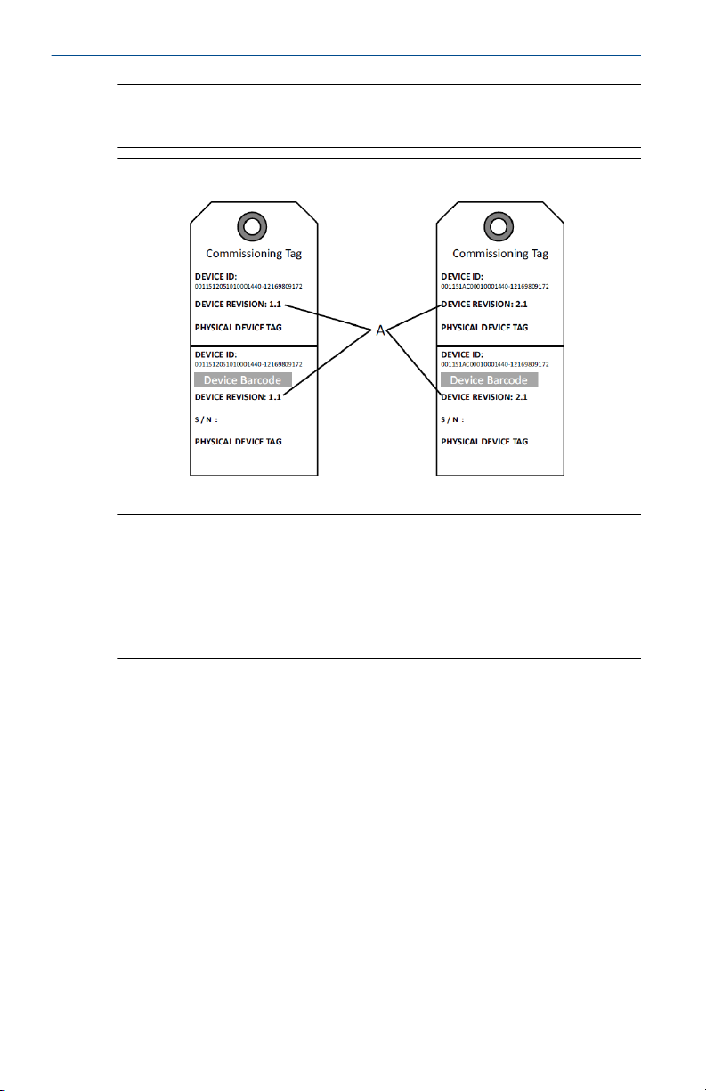
Commissioning (paper) tag
To identify which device is at a particular location use the removable tag
provided with the transmitter. Ensure the physical device tag (PD tag field) is
properly entered in both places on the removable commissioning tag and
tear off the bottom portion for each transmitter.
Page 8
Quick Start Guide November 2019
Note
The device description loaded in the host system must be at the same
revision as this device.
Figure 2-3: Commissioning Tag
A. Device revision
Note
The device description loaded in the host system must be at the same
revision as this device. The device description can be downloaded from the
host system website or Emerson.com/Rosemount by selecting Download
Device Drivers under Product Quick Links. You can also visit Fieldbus.org and
select End User Resources.
2.3
8 Emerson.com/Rosemount
Setting security switch
Prerequisites
Set Simulate and Security switch configuration before installation as shown
in Figure 2-4.
• The simulate switch enables or disables simulated alerts and simulated
AI Block status and values. The default simulate switch position is
enabled.
• The Security switch allows (unlocked symbol) or prevents (locked
symbol) any configuration of the transmitter.
• Default security is off (unlocked symbol).
• The security switch can be enabled or disabled in software.
Use the following procedures to change the switch configuration:
Page 9

A
B
November 2019 Quick Start Guide
Procedure
1. If the transmitter is installed, secure the loop, and remove power.
2. Remove the housing cover opposite the field terminal side. Do not
remove the instrument cover in explosive atmospheres when the
circuit is live.
3. Slide the security and simulate switches into the preferred position.
4. Reattach transmitter housing cover; it is recommended the cover be
tightened until there is no gap between the cover and housing to
comply with explosion proof requirements.
2.4 Setting simulate switch
The simulate switch is located on the electronics. It is used in conjunction
with the transmitter simulate software to simulate process variables and/or
alerts and alarms. To simulate variables and/or alerts and alarms, the
simulate switch must be moved to the enable position and the software
enabled through the host. To disable simulation, the switch must be in the
disable position or the software simulate parameter must be disabled
through the host.
Figure 2-4: Transmitter Electronics Board
Aluminum Polished 316 SST
A. Simulate switch
B. Security switch
Quick Start Guide 9
Page 10

Quick Start Guide November 2019
2.5 Connect the wiring and power up
Use copper wire of sufficient size to ensure the voltage across the
transmitter power terminals does not drop below 9 Vdc. Power supply
voltage can be variable, especially under abnormal conditions such as when
operating on battery backup. A minimum of 12 Vdc under normal operating
conditions is recommended. Shielded twisted pair type A cable is
recommended.
Use the following steps to wire the transmitter:
Procedure
1. To power the transmitter, connect the power leads to the terminals
indicated on the terminal block label.
Note
The Rosemount 2051 power terminals are polarity insensitive, which
means the electrical polarity of the power leads does not matter
when connecting to the power terminals. If polarity sensitive devices
are connected to the segment, terminal polarity should be followed.
When wiring to the screw terminals, the use of crimped legs is
recommended.
2. Ensure full contact with terminal block screw and washer. When
using a direct wiring method, wrap wire clockwise to ensure it is in
place when tightening the terminal block screw. No additional power
is needed.
Note
The use of a pin or a ferrule wire terminal is not recommended as the
connection may be more susceptible to loosening over time or under
vibration.
3. Ensure proper grounding. It is important the instrument cable shield
be:
4. Trimmed close and insulated from touching the transmitter housing.
5. Connected to the next shield if cable is routed through a junction
box.
6. Connected to a good earth ground at the power supply end.
7. If transient protection is needed, refer to section “Signal ground
wiring” for grounding instructions.
8. Plug and seal unused conduit connections.
9. Reattach the transmitter covers. It is recommended that the cover be
tightened until there is no gap between the cover and the housing.
10 Emerson.com/Rosemount
Page 11

DP
A
B
D
E
C
DP
A
B
D
E
C
November 2019 Quick Start Guide
10. The covers must only be capable of being released or removed with
the aid of a tool to comply with applicable ordinary locations
requirements.
Example
Figure 2-5: Wiring
Aluminum Polished 316 SST
A. Minimize distance
B. Trim shield and insulate
C. Protective grounding terminal (do not ground cable shield at the
transmitter)
D. Insulate shield
E. Connect shield back to the power supply ground
2.5.1 Signal ground wiring
Do not run signal wiring in conduit or open trays with power wiring, or near
heavy electrical equipment. Grounding terminations are provided on the
outside of the electronics housing and inside the terminal compartment.
These grounds are used when transient protect terminal blocks are installed
or to fulfill local regulations.
Procedure
1. Remove the field terminals housing cover.
2. Connect the wiring pair and ground as indicated in Figure 2-5.
a) Trim the cable shield as short as practical and insulate from
touching the transmitter housing.
Quick Start Guide 11
Page 12

Quick Start Guide November 2019
Note
Do NOT ground the cable shield at the transmitter; if the cable shield
touches the transmitter housing, it can create ground loops and
interfere with communications.
3. Continuously connect the cable shields to the power supply ground.
a) Connect the cable shields for the entire segment to a single
good earth ground at the power supply.
Note
Improper grounding is the most frequent cause of poor segment
communications.
4. Replace the housing cover. It is recommended that the cover be
tightened until there is no gap between the cover and the housing.
a) The covers must only be capable of being released or
removed with the aid of a tool to comply with applicable
ordinary locations requirements.
5. Plug and seal unused conduit connections.
Note
The Rosemount 2051HT polished 316 SST housing only provides
ground termination inside the terminal compartment.
12 Emerson.com/Rosemount
Page 13

November 2019 Quick Start Guide
3 Basic configuration
3.1 Configuration tasks
The transmitter can be configured via either the local operator interface
(LOI) - option code M4, or via a Class 2 Master (DD or DTM™ based). The two
basic configuration tasks for the PROFIBUS PA Pressure transmitter are:
Procedure
1. Assign address
2. Configure engineering units (scaling).
Note
Rosemount 2051 PROFIBUS Profile 3.02 devices are set to
identification number adaptation mode when shipped from the
factory. This mode allows the transmitter to communicate with any
Profibus control host with either the generic Profile GSD (9700) or
Rosemount 2051 specific GSD (3333) loaded on the host; therefore,
it is not required to change the transmitter identification number at
startup.
3.2 Assign address
The transmitter is shipped with a temporary address of 126. This must be
changed to a unique value between 0 and 125 in order to establish
communication with the host. Usually, addresses 0–2 are reserved for
masters or couplers, therefore transmitter addresses between 3 and 125 are
recommended.
Address can be set via either:
• LOI - see Table 3-1
• Class 2 Master - see Class 2 Master manual for setting address
3.3
Quick Start Guide 13
Configure engineering units
Unless otherwise requested, the transmitter ships with the following
settings:
• Measurement mode: Pressure
• Engineering units: Inches H2O
• Scaling: None
Engineering units should be confirmed or configured before installation.
Units can be configured for pressure, flow, or level measurement.
Page 14

Quick Start Guide November 2019
Measurement type, Units, Scaling, and Low Flow Cutoff (when applicable)
can be set via either:
• LOI – see Table 3-1
• Class 2 master – see Table 3-2 for parameter configuration
3.4 Configuration tools
Local operator interface (LOI)
When ordered, the LOI can be used for commissioning the device. To
activate the LOI, push either configuration button located under the top tag
of the transmitter, or use the push buttons located on the LCD. See Table
Table 3-1 for operation and menu information. The security jumper prevents
changes made using the LOI.
Table 3-1: LOI Button Operation
(1)
Button
Action Navigation Character
Scroll Moves down
menu
categories
Entry
Changes
character
(2)
value
Save?
Changes
between Save
and Cancel
Enter Selects menu
category
(1) Reverse scroll also available (scroll + enter).
(2) Characters blink when they can be changed.
Enters
character and
advances
Saves
Figure 3-1: LOI Menu
3.5
Class 2 Master
The Rosemount 2051 Profibus DD and DTM files are available at
Emerson.com or by contacting your local salesperson. See Table 3-2 for
steps to configure the transmitter for Pressure measurement. See the
Rosemount 2051 Reference Manual for Level configuration instructions.
14 Emerson.com/Rosemount
Page 15

November 2019 Quick Start Guide
Table 3-2: Pressure Configuration via Class 2 Master
Steps Actions
Put Transducer Block into Out of Service
Set blocks to Out of Service
Select Measurement Type Set Primary Value type to Pressure
Select Units
Enter Scaling
Set blocks to Auto
mode
Put Analog Input Block into Out of Service
mode
Set Engineering Units
Primary and secondary units must match
Configure engineering units under analog
output block
Set Scale In in Transducer Block to 0–100
Set Scale Out in Transducer Block to 0–100
Set PV Scale in Analog Input Block to 0–100
Set Out Scale in Analog Input Block to 0–100
Set Linearization in Analog Input Block to No
Linearization
Put Transducer Block into Auto mode
Put Analog Input Block into Auto mode
3.6 Host integration
Control host (Class 1)
The Rosemount 2051 device utilizes condensed status as recommended by
the Profile 3.02 specification and NE 107. See manual for condensed status
bit assignment information.
The appropriate GSD file must be loaded on the control host - Rosemount
2051 specific (rmt3333.gsd) or Profile 3.02 Generic (pa139700.gsd). These
files can be found on Emerson.com or Profibus.com.
Configuration host (class 2)
The appropriate DD or DTM file must be installed in the configuration host.
These files can be found at Emerson.com.
Quick Start Guide 15
Page 16

Quick Start Guide November 2019
4 Product certifications
Rev 1.2
4.1 European Directive Information
A copy of the EU Declaration of Conformity can be found at the end of the
Quick Start Guide. The most recent revision of the EU Declaration of
Conformity can be found at Emerson.com/Rosemount.
4.2 Ordinary Location Certification
As standard, the transmitter has been examined and tested to determine
that the design meets the basic electrical, mechanical, and fire protection
requirements by a nationally recognized test laboratory (NRTL) as accredited
by the Federal Occupational Safety and Health Administration (OSHA).
4.3 Installing Equipment in North America
The US National Electrical Code® (NEC) and the Canadian Electrical Code
(CEC) permit the use of Division marked equipment in Zones and Zone
marked equipment in Divisions. The markings must be suitable for the area
classification, gas, and temperature class. This information is clearly defined
in the respective codes.
4.4 Hazardous Locations Certifications
Note
Device ambient temperature ratings and electrical parameters may be
limited to the levels dictated by the hazardous location certificate
parameters.
4.5
4.5.1 I5 USA Intrinsic Safety (IS) and Nonincendive (NI)
16 Emerson.com/Rosemount
North America
Certificate:
Standards:
Markings:
Specific Condition of Use:
1. 1. The Model 2051 transmitter housing contains aluminum and is
FM16US0231X (HART)
FM Class 3600 – 2011, FM Class 3610 – 2010, FM Class 3611
– 2004, FM Class 3810 – 2005, ANSI/NEMA 250 – 2008
IS CL I, DIV 1, GP A, B, C, D; CL II, DIV 1, GP E, F, G; Class III; DIV
1 when connected per Rosemount drawing 02051-1009;
Class I, Zone 0; AEx ia IIC T4; NI CL 1, DIV 2, GP A, B, C, D;
T4(-50 °C ≤ Ta ≤ +70 °C); Type 4x
considered a potential risk of ignition by impact or friction. Care must
Page 17

November 2019 Quick Start Guide
be taken into account during installation and use to prevent impact
and friction.
Certificate:
Standards:
2041384 (HART/Fieldbus/PROFIBUS®)
ANSI/ISA 12.27.01-2003, CSA Std. C22.2 No.142-M1987, CSA
Std. C22.2. No.157-92
Markings:
IS CL I, DIV 1, GP A, B, C, D; CL II, DIV 1, GP E, F, G; Class III; DIV
1 when connected per Rosemount drawing 02051-1009;
Class I, Zone 0; AEx ia IIC T4; NI CL 1, DIV 2, GP A, B, C, D;
T4(-50 °C ≤ Ta ≤ +70 °C); Type 4x
4.5.2 I6 Canada Intrinsic Safety
Certificate:
Standards:
Markings:
2041384
CSA Std. C22.2 No. 142 - M1987, CSA Std. C22.2 No. 213 M1987, CSA Std. C22.2 No. 157 - 92, CSA Std. C22.2 No. 213
- M1987, ANSI/ISA 12.27.01 – 2003, CAN/CSA-E60079-0:07,
CAN/CSA-E60079-11:02
Intrinsically safe for Class I, Division 1, Groups A, B, C, and D
when connected in accordance with Rosemount drawing
02051-1008. Ex ia IIC T3C. Single Seal. Enclosure Type 4X
4.6 Europe
4.6.1 I1 ATEX Intrinsic Safety
Certificate:
Standards:
Markings:
Baseefa08ATEX0129X
EN60079-0:2012+A11:2013, EN60079-11:2012
Ex II 1 G Ex ia IIC T4 Ga (–60 °C ≤ Ta ≤ +70 °C)
Table 4-1: Input Parameters
Parameter HART Fieldbus/PROFIBUS
Voltage U
Current I
Power P
i
Capacitance Ci0.012 μF 0 μF
Inductance Li0 mH 0 mH
Quick Start Guide 17
30 V 30 V
i
200 mA 300 mA
i
1 W 1.3 W
Page 18

Quick Start Guide November 2019
Specific Conditions of Safe Use (X):
1. If the equipment is fitted with an optional 90 V transient suppressor,
it is incapable of withstanding the 500 V isolation from earth test and
this must be taken into account during installation.
2. The enclosure may be made of aluminum alloy and given a protective
polyurethane paint finish; however care should be taken to protect it
from impact and abrasion when located in Zone 0 from earth test
and this must be taken into account during installation.
4.7 International
4.7.1 I7 IECEx Intrinsic Safety
Certificate:
Standards:
Markings:
IECEx BAS 08.0045X
IEC 60079-0:2011, IEC 60079-11:2011
Ex ia IIC T4 Ga (–60 °C ≤ Ta ≤ +70 °C)
Table 4-2: Input Parameters
Parameter HART Fieldbus/PROFIBUS
Voltage U
Current I
Power P
i
Capacitance Ci0.012 μF 0 μF
Inductance Li0 mH 0 mH
30 V 30 V
i
200 mA 300 mA
i
1 W 1.3 W
Specific Conditions of Safe Use (X):
1. If the equipment is fitted with an optional 90 V transient suppressor,
it is incapable of withstanding the 500 V isolation from earth test and
this must be taken into account during installation.
2. The enclosure may be made of aluminum alloy and given a protective
polyurethane paint finish; however care should be taken to protect it
from impact and abrasion when located in Zone 0.
3. The equipment contains thin wall diaphragms. The installation,
maintenance and use shall take into account the environmental
conditions to which the diaphragms will be subjected. The
manufacturer’s instructions for installation and maintenance shall be
followed in detail to assure safety during its expected lifetime.
18 Emerson.com/Rosemount
Page 19

November 2019 Quick Start Guide
4.8 Additional Certifications
®
3-A
All Rosemount 2051HT transmitters with the following connections are 3-A
approved and labeled:
T32: 1½-in. Tri-Clamp
T42: 2-in. Tri-Clamp
If process connection B11 is selected, please reference the ordering table of
the Rosemount 1199 Diaphragm Seal Product Data Sheet for availability of
3-A certifications.
A 3-A certificate of compliance is available by selecting option code QA.
EHEDG
All Rosemount 2051HT transmitters with the following connections are
EHEDG approved and labeled:
T32: 1½-in. Tri-Clamp
T42: 2-in. Tri-Clamp
If process connection B11 is selected, please reference the ordering table of
the Rosemount 1199 Diaphragm Seal Product Data Sheet for availability of
EHEDG certifications.
An EHEDG certificate of compliance is available by selecting option code QE.
Ensure gasket selected for installation is approved to meet both application
and EHEDG certification requirements.
Quick Start Guide 19
Page 20

Quick Start Guide November 2019
4.9 Rosemount 2051HT Declaration of Conformity
20 Emerson.com/Rosemount
Page 21

November 2019 Quick Start Guide
Quick Start Guide 21
Page 22

Quick Start Guide November 2019
22 Emerson.com/Rosemount
Page 23

ᴹ
China RoHS
㇑᧗⢙䍘䎵䗷ᴰབྷ⎃ᓖ䲀٬Ⲵ䜘Ԧරࡇ㺘
Rosemount 2051HT
List of Rosemount 2051HT Parts with China RoHS Concentration above MCVs
䜘Ԧ〠
Part Name
ᴹᇣ⢙䍘
/ Hazardous Substances
䫵
Lead
(Pb)
⊎
Mercury
(Hg)
䭹
Cadmium
(Cd)
ޝԧ䬜
Hexavalent
Chromium
(Cr +6)
ཊⓤ㚄㤟
Polybrominated
biphenyls
(PBB)
ཊⓤ㚄㤟䟊
Polybrominated
diphenyl ethers
(PBDE)
⭥ᆀ㓴Ԧ
Electronics
Assembly
X O O O O O
༣փ㓴Ԧ
Housing
Assembly
O O O O O O
Րᝏಘ㓴Ԧ
Sensor
Assembly
X O O O O O
ᵜ㺘Ṭ㌫ᦞ
SJ/T11364
Ⲵ㿴ᇊ㘼ࡦ
This table is proposed in accordance with the provision of SJ/T11364.
O:
Ѫ䈕䜘ԦⲴᡰᴹ൷䍘ᶀᯉѝ䈕ᴹᇣ⢙䍘Ⲵ䟿൷վҾ
GB/T 26572
ᡰ㿴ᇊⲴ䲀䟿㾱≲
O: Indicate that said hazardous substance in all of the homogeneous materials for this part is below the limit requirement of
GB/T 26572.
X:
Ѫ൘䈕䜘Ԧᡰ֯⭘Ⲵᡰᴹ൷䍘ᶀᯉ䟼ˈ㠣ቁᴹа㊫൷䍘ᶀᯉѝ䈕ᴹᇣ⢙䍘Ⲵ䟿儈Ҿ
GB/T 26572
ᡰ㿴ᇊⲴ䲀䟿㾱≲
X: Indicate that said hazardous substance contained in at least one of the homogeneous materials used for this part is above
the limit requirement of GB/T 26572.
November 2019 Quick Start Guide
4.10 China RoHS
Quick Start Guide 23
Page 24

*00825-0300-4591*
00825-0300-4591, Rev. BA
Quick Start Guide
November 2019
Global Headquarters
Emerson Automation Solutions
6021 Innovation Blvd.
Shakopee, MN 55379, USA
+1 800 999 9307 or +1 952 906 8888
+1 952 204 8889
RFQ.RMD-RCC@Emerson.com
Latin America Regional Office
Emerson Automation Solutions
1300 Concord Terrace, Suite 400
Sunrise, FL 33323, USA
+1 954 846 5030
+1 954 846 5121
RFQ.RMD-RCC@Emerson.com
Asia Pacific Regional Office
Emerson Automation Solutions
1 Pandan Crescent
Singapore 128461
+65 6777 8211
+65 6777 0947
Enquiries@AP.Emerson.com
North America Regional Office
Emerson Automation Solutions
8200 Market Blvd.
Chanhassen, MN 55317, USA
+1 800 999 9307 or +1 952 906 8888
+1 952 204 8889
RMT-NA.RCCRFQ@Emerson.com
Europe Regional Office
Emerson Automation Solutions Europe
GmbH
Neuhofstrasse 19a P.O. Box 1046
CH 6340 Baar
Switzerland
+41 (0) 41 768 6111
+41 (0) 41 768 6300
RFQ.RMD-RCC@Emerson.com
Middle East and Africa Regional Office
Emerson Automation Solutions
Emerson FZE P.O. Box 17033
Jebel Ali Free Zone - South 2
Dubai, United Arab Emirates
+971 4 8118100
+971 4 8865465
RFQ.RMTMEA@Emerson.com
Linkedin.com/company/Emerson-
Automation-Solutions
Twitter.com/Rosemount_News
Facebook.com/Rosemount
Youtube.com/user/
RosemountMeasurement
©
2019 Emerson. All rights reserved.
Emerson Terms and Conditions of Sale are
available upon request. The Emerson logo is a
trademark and service mark of Emerson Electric
Co. Rosemount is a mark of one of the Emerson
family of companies. All other marks are the
property of their respective owners.
 Loading...