

Page 1
Product Data Sheet
00813-0200-4591, Rev AC
Rosemount™ 2051HT Hygienic Pressure
Transmitter
July 2019
■
Hygienic design conforms to 3-A® and EHEDG standards
■
Reference accuracy up to 0.1%
■
Rated for SIP/CIP process temperatures up to 302 °F (150 °C)
■
Rangeability of 50:1
■
Up to two year stability
■
4–20 mA/HART®, PROFIBUS® PA or FOUNDATION™ Fieldbus output and AMS Suite: Intelligent Device
Manager compatibility ensures easier configurations, calibrations, and operation
■
Proven technology from Emerson improves process reliability and robustness
Page 2

Rosemount 2051HT July 2019
Features and benefits
A foundation of reliable pressure measurement for the Life Science and Food and Beverage industries
Work more efficiently with the Rosemount™ 2051HT Hygienic Pressure Transmitter, an industry standard device that delivers
reliable process data and consistent batch results.
Hygienic design conforms to hygienic standards
The hygienic design of the Rosemount 2051HT features 32 μ-in. Ra mechanically polished wetted surfaces. The stainless steel (SST)
design is free of voids and crevices to ensure easy cleaning and wipe downs. The Rosemount 2051HT is also 3-A and EHEDG
approved.
Proven Emerson technology improves process reliability and robustness
The Rosemount 2051HT uses the same proven sensor and electronics technology found in other industry leading Rosemount
transmitters from Emerson. This ensures the transmitter to be robust and reliable, which improves your process consistency and
increases your plant availability
4–20 mA/HART®, PROFIBUS®, or FOUNDATION Fieldbus output and AMS Suite compatibility ensures easier configurations, calibrations and operation
Lower maintenance costs with AMS Suite software, improve device performance and enable easier configuration and setup.
Combining AMS Suite with the Rosemount 2051HT can also provide you with audit trail information to make FDA compliance
simpler and paper free.
Easy to use local configuration capabilities
The optional Local Operator Interface (LOI) features straightforward menus and built-in configuration buttons so you can
commission without complicated training or additional tools.
Contents
Features and benefits........................................................................................................................................................................ 2
Ordering Information........................................................................................................................................................................ 3
Specifications.................................................................................................................................................................................... 6
Product certifications...................................................................................................................................................................... 15
Dimensional drawings..................................................................................................................................................................... 16
Options........................................................................................................................................................................................... 18
2 www.emerson.com
Page 3

July 2019 Rosemount 2051HT
Ordering Information
Table 1: Rosemount™ 2051HT Hygienic In-line Pressure Transmitter Ordering Information
The starred offerings (★) represent the most common options and should be selected for best delivery. The non-starred offerings
are subject to additional delivery lead time.
Rosemount model
2051HT Hygienic Pressure Transmitter ★
Pressure type
G Gage ★
A Absolute ★
Performance class
Range 1–3 Range 0
B 0.10% span accuracy and 2-year stability 0.10% span accuracy and 6 month stability ★
C 0.20% span accuracy and 1-year stability 0.20% span accuracy and 6 month stability ★
Pressure range
Rosemount 2051HTG
(1)
Rosemount 2051HTA
0 –5 to 5 psi (–0,34 to 0,34 bar-g) N/A ★
1 –14.7 to 30 psi (–1,01 to 2,1 bar-g) 0 to 30 psia (0 to 2,1 bar-a) ★
2 –14.7 to 150 psi (–1,01 to 10,3 bar-g) 0 to 150 psia (0 to 10,3 bar-a) ★
3 –14.7 to 300 psi (–1,01 to 20,7 bar-g) N/A ★
Transmitter output
A 4–20 mA with digital signal based on HART® Protocol ★
F FOUNDATION™ Fieldbus Protocol ★
W PROFIBUS® PA Protocol
Sensor fill fluid
3 Neobee® M-20 ★
Housing material
1 Crevice-free polished 316 SST ★
2 Aluminum ★
Conduit entry size
A 1/2–14 NPT ★
(2)
B
Process connection style
M20 x 1.5 ★
(3)
Type Size Diaphragm Upper housing/extension
T32 Tri-Clamp 1 1/2-in. 316L SST 316L SST ★
T42 Tri-Clamp 2-in. 316L SST 316L SST ★
B11 Assemble to one Rosemount 1199 Diaphragm Seal with SST transmitter flange ★
3
Page 4

Rosemount 2051HT July 2019
Table 1: Rosemount™ 2051HT Hygienic In-line Pressure Transmitter Ordering Information (continued)
Rosemount model
Options (include with selected model number)
Extended product warranty
WR3 3-year limited warranty ★
WR5 5-year limited warranty ★
Plantweb™ control functionality
A01 FOUNDATION™ Fieldbus advanced control function block suite ★
Product certifications
I1 ATEX intrinsic safety ★
I5 USA intrinsic safety and non incendive ★
I6 Canada intrinsic safety ★
I7 IECEx intrinsic safety ★
Display and interface options
(5)
M4
LCD display with LOI ★
(4)
M5 LCD display ★
Configuration buttons
(5)(6)
D4 Analog zero and span ★
DZ Digital zero trim ★
Transient terminal block
T1 Transient protection terminal block ★
Software configuration
(5)
C1 Custom software configuration ★
Alarm levels
C4 NAMUR alarm and saturation levels, high alarm ★
CN NAMUR alarm and saturation levels, low alarm ★
CR Custom alarm and saturation signal levels, high alarm (requires C1 and Configuration Data Sheet) ★
C7 Custom alarm and saturation signal levels, low alarm (requires C1 and Configuration Data Sheet) ★
CT Low alarm (standard Rosemount alarm and saturation levels) ★
Special cleaning
P2 Cleaning for special services
P3 Cleaning for <1 PPM Chlorine/Fluorine
Wetted surface finish certification
Q16 Surface Finish Certification ★
Calibration Certification
Q4 Calibration Certificate ★
4 www.emerson.com
Page 5

July 2019
Rosemount 2051HT
Table 1: Rosemount™ 2051HT Hygienic In-line Pressure Transmitter Ordering Information (continued)
Rosemount model
QP Calibration certificate and tamper evident seal ★
Material traceability certification
Q8 Material traceability certification per EN 10204 3.1 ★
Certificate of compliance to 3-A
QA Certificate of compliance to 3-A ★
Certificate of compliance to EHEDG
QE Certification of compliance to EHEDG ★
Conduit electrical connector
GE M12, 4-pin, male connector (eurofast®) ★
GM A size mini, 4-pin, male connector (minifast®) ★
Increased Ingress Protection
V9 Transmitter IP69K Rating
★
(SST only)
Rosemount 2051HTG lower range limit varies with atmospheric pressure.
(1)
For aluminum housings, transmitter conduit entry will be 1/2-NPT and a 1/2-NPT to M20 thread adapter will be provided.
(2)
All process wetted parts have surface finish of Ra < 32 μ-in (0.81 μ-m) standard unless otherwise specified.
(3)
Housing material option 1 comes with polycarbonate cover standard. Housing material optin 2 comes with AI and glass cover standard.
(4)
Only available with HART 4—20mA output (code A) and PROFIBUS PA (code W).
(5)
CDS required with order, available with output code A only.
(6)
5
Page 6

Rosemount 2051HT July 2019
Specifications
Performance specifications
For zero-based spans, reference conditions, Neobee® M-20 oil fill, SST materials, 1 ½-in. Tri-Clamp process connections, silicone
gasket material, clamping torque of 45 in-lb, digital trim values set to equal range points.
For assemblies attached to a Rosemount™ 1199 Diaphragm Seal (option code B11), use Instrument Toolkit™ or the QZ option to
quantify the total performance of the assembly under operating conditions.
Note
QZ option is to be added to the Rosemount 1199 model string.
Table 2: Reference accuracy
Stated reference accuracy equations include terminal based linearity, hysteresis, and repeatability.
Range Performance class option B Performance class option C
0 ±0.10% of span
For spans less than 5:1, accuracy =
1 ±0.10% of span
For spans less than 5:1, accuracy =
2 ±0.10% of span
For spans less than 10:1, accuracy =
3 ±0.10% of span
For spans less than 2:1, accuracy =
±0.20% of span
For spans less than 5:1,
±0.20% of span
For spans less than 5:1,
±0.20% of span
For spans less than 10:1,
±0.20% of span
For spans less than 2:1,
Table 3: Long term stability
±50 °F (28 °C) temperature changes, and up to 300 psi (20,68 bar) line pressure
Range Performance class option B Performance class option C
0 ±0.3% of URL for 1 year ±0.2% of URL for 6 months
1–2 ±0.15% of URL for 2 years ±0.15% of URL for 1 year
3 ±0.2% of URL for 2 years ±0.2% of URL for 1 year
6 www.emerson.com
Page 7
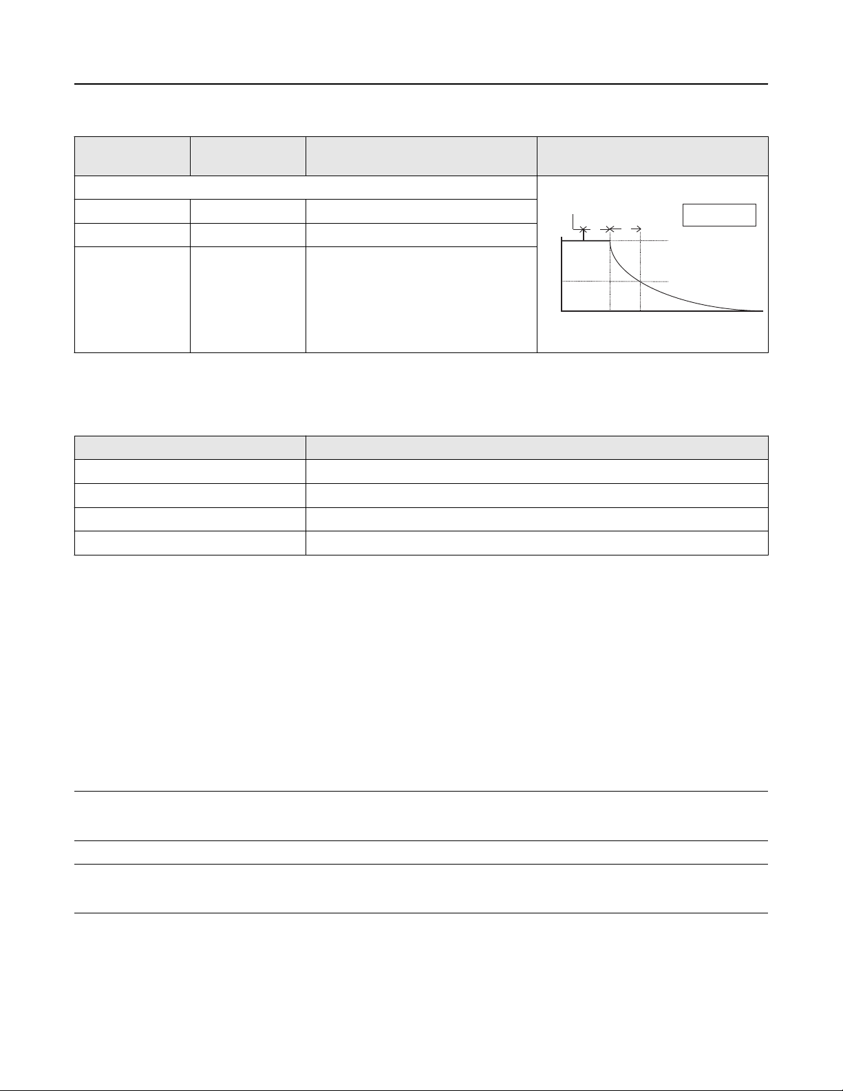
Pressure released
TdT
c
Transmitter Output vs. Time
100%
36.8%
0%
Time
63.2% of total
step change
= Dead time
= Time constant
T
d
T
c
Response time =
T
d
+
T
c
July 2019
Table 4: Dynamic performance
4–20 mA HART
Protocol
Total response time (Td +Tc)
(3)
®
(1)
FOUNDATION™ Fieldbus and PROFIBUS
PA Protocols
:
Ranges 0–3 145 ms 197 ms
Dead time (Td) 60 ms (nominal) 112 ms
(2)
Rosemount 2051HT
®
Typical HART transmitter response
time
Update rate 22 times per
second
22 times per second
(FOUNDATION Fieldbus)
20 times per second (PROFIBUS)
Dead time and update rate apply to all models and ranges; analog output only.
(1)
Transducer Block response time, Analog Input block execution time not included.
(2)
Nominal total response time at 75 °F (24 °C) reference conditions.
(3)
Table 5: Ambient temperature effect per 50 °F (28 °C)
Range Ambient temperature effect
0 ±(0.70% URL + 0.30% span)
1 ±(0.35% URL + 0.20% span)
2 ±(0.10% URL + 0.075% span)
3 ±(0.10% URL + 0.075% span)
For assemblies attached to a Rosemount 1199 Diaphragm Seal (option code B11) see Instrument Toolkit
Mounting position effects
Zero shifts to ±2.5 inH2O (6,22 mbar), which can be calibrated out. No span effect.
™
Vibration effect
Less than ±0.1% of URL when tested per the requirements of IEC 60770 control room level.
Electromagnetic compatibility (EMC)
Meets all industrial environment requirements of EN61326. Maximum deviation <1% Span during EMC disturbance.
Note
During surge event, device with 4-20mA (Transmitter output option code A) may exceed maximum EMC deviation limit or reset;
however, device will self-recover and return to normal operation within specified start-up time.
Note
During ESD event, device with FOUNDATION™ Fieldbus or PROFIBUS® (Transmitter output option code F or W) may exceed maximum
EMC deviation limit, however, device will self-recover and return to normal operation within specified start-up time.
Transient protection (option code T1)
Tested in accordance with IEEE C62.41.2-2002, location category B.
6 kV crest (0.5 μs–100 kHz)
7
Page 8
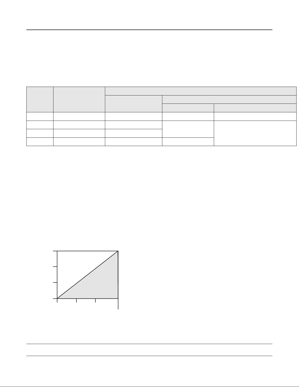
Communication requires a minimum
loop resistance of 250 ohms.
42.4
Voltage (Vdc)
10.5
20
30
1387
1000
500
0
Operating
region
Load (Ωs)
Rosemount 2051HT
3 kA crest (8 x 20 μs)
6 kV crest (1.2 x 50 μs)
Functional specifications
Table 6: Range and Sensor Limits
Range Minimum span Range and sensor limits
URL LRL
2051HTA 2051HTG
0 0.50 psi (0,034 bar) 5.00 psi (0,34 bar) N/A –5.00 psig (–0,34 bar)
1 1.00 psi (0,069 bar) 30.00 psi (2,07 bar) 0 psia (0 bar) –14.70 psig (–1,01 bar)
2 1.50 psi (0,10 bar) 150.00 psi (10,34 bar)
3 15.00 psi (1,03 bar) 300.00 psi (20,68 bar) N/A
Assumes atmospheric pressure of 14.70 psia (1,01 bar-a).
(1)
Service
Liquid, gas, and vapor applications
(1)
July 2019
4–20 mA HART® (output code A)
Power supply
External power supply required. Standard transmitter (4–20 mA) operates on 10.5–42.4 Vdc with no load.
Load limitations
Maximum loop resistance is determined by the voltage level of the external power supply described by:
Max. loop resistance = 43.5 (Power Supply voltage – 10.5)
Communication requires a minimumloop resistance of 250 ohms.
Note
For CSA approval, power supply must not exceed 42.4 V.
8 www.emerson.com
Page 9

July 2019 Rosemount 2051HT
Indication
Optional two-line LOI/LCD display
Optional configuration buttons
Configuration buttons need to be specified:
Digital zero trim (option code DZ) changes digital value of the transmitter and is used for performing a sensor zero trim.
Analog zero span (option code D4) changes analog value and can be used to rerange the transmitter with an applied pressure.
Output
Two-wire 4–20 mA, user selectable for linear or square root output. Digital process variable superimposed on 4–20 mA signal,
available to any host that conforms to HART Protocol.
The Rosemount 2051 comes with Selectable HART Revisions. Digital communications based on HART Revision 5 (default) or
Revision 7 (option code HR7) protocol can be selected. The HART revision can be switched in the field using any HART based
configuration tool or the optional local operator interface (M4).
Local Operator Interface (LOI)
The LOI utilizes a two-button menu with internal and external/terminal side configuration buttons. Internal buttons are always
configured for LOI. External buttons can be configured for either LOI (option code M4), Analog zero and span (option code D4) or
digital zero trim (option code DZ). See Rosemount 2051 Reference Manual for LOI configuration menu.
FOUNDATION Fieldbus (output code F)
Power supply
External power supply required; transmitters operate on 9.0 to 32.0 Vdc transmitter terminal voltage.
Current draw
17.5 mA for all configurations (including LCD display option)
Indication
Optional two-line LCD display
FOUNDATION Fieldbus block Execution Times
Block
Resource N/A
Sensor and SPM Transducer N/A
LCD Display N/A
Analog Input 1, 2 20 milliseconds
PID 25 milliseconds
Input Selector 20 milliseconds
Arithmetic 20 milliseconds
Signal Characterizer 20 milliseconds
Execution time
Integrator 20 milliseconds
Output Splitter 20 milliseconds
Control Selector 20 milliseconds
9
Page 10

Rosemount 2051HT
FOUNDATION Fieldbus parameters
Links 25 (max.)
Virtual Communications Relationships (VCR) 20 (max.)
July 2019
FOUNDATION Fieldbus function blocks (option A01)
Resource Block
The resource block contains diagnostic, hardware, and electronics information. There are no linkable inputs or outputs to the
resource block.
Sensor transducer block
The sensor transducer block contains sensor information and the ability to calibrate the pressure sensor or recall factory calibration.
LCD transducer block
The LCD transducer block is used to configure the LCD display meter.
Analog input (AI) block
The analog input Function Block processes the measurements from the sensor and makes them available to other function blocks.
The output value from the AI Block is in engineering units and contains a status indicating the quality of the measurement. The AI
Block is widely used for scaling functionality.
Input selector (ISEL) block
The Input Selector Function Block can be used to select the first good, hot backup, maximum, minimum, or average of as many as
eight input values and place it at the output. The block supports signal status propagation.
Integrator (INT) block
The Integrator Function Block integrates one or two variables over time. The block compares the integrated or accumulated value
to pre-trip and trip limits and generates discrete output signals when the limits are reached.
The INT function block is used as a totalizer. This block will accept up to two inputs, has six options how to totalize the inputs, and
two trip outputs.
Arithmetic (ARTH) block
The Arithmetic Function Block provides the ability to configure a range extension function for a primary input. It can also be used to
compute nine different arithmetic functions including flow with partial density compensation, electronic remote seals, hydrostatic
tank gaging, ratio control, and others.
Signal characterizer (SGCR) block
The Signal Characterizer Function Block characterizes or approximates any function that defines an input/output relationship. The
function is defined by configuring as many as twenty X,Y coordinates. The block interpolates an output value for a given input value
using the curve defined by the configured coordinates. Two separate analog input signals can be processed simultaneously to give
two corresponding separate output values using the same defined curve.
10 www.emerson.com
Page 11

July 2019
Proportional/Integral/Derivative (PID) block
The PID Function Block combines all of the necessary logic to perform PID control. The block supports mode control, signal scaling,
and limiting, feed forward control, override tracking, alarm limit detection, and signal status propagation.
Control selector block
The Control Selector Function Block selects one of two or three inputs to be the output. The inputs are normally connected to the
outputs of PID or other function blocks. One of the inputs would be considered normal and the other two overrides.
Output splitter block
The Output Splitter Function Block provides the capability to drive two control outputs from a single input. It takes the output of
one PID or other control block to control two valves or other actuators.
Backup link active scheduler (LAS)
The transmitter can function as a link active scheduler if the current link master device fails or is removed from the segment.
Rosemount 2051HT
PROFIBUS® PA Protocol (output code W)
Profile version
3.02
Power supply
External power supply required; transmitters operate on 9.0 to 32.0 Vdc transmitter terminal voltage. FISCO transmitters operate
on 9.0 to 17.5 Vdc.
Current draw
17.5 mA for all configurations (including LCD display option)
Output update rate
50 times per second
Standard function blocks
Analog input (AI block)
The AI function block processes the measurements and makes them available to the host device. The output value from the AI
block is in engineering units and contains a status indicating the quality of the measurement.
Physical block
The physical block defines the physical resources of the device including type of memory, hardware, electronics and diagnostic
information.
Transducer block
Contains actual sensor measurement data including the sensor diagnostics and the ability to trim the pressure sensor or recall
factory defaults.
Sensor overpressure limits
■
Range 0: 60 psi (4,14 bar)
■
Range 1: 150 psi (10,34 bar)
■
Range 2: 300 psi (20,68 bar)
■
Range 3: 600 psi (41,36 bar)
Note
Overpressure limit is dependent on the clamp/pressure adapter or sensor rating (whichever is lower).
11
Page 12

Rosemount 2051HT July 2019
Sensor burst pressure
All ranges: 900 psi (62,05 bar)
Temperature limits
Ambient
32 to 185 °F (0 to 85 °C)
175 °F with LCD display
Storage
–22 to 185 °F (–30 to 85 °C)
Process temperature limits
32 to 302 °F (0 to 150 °C)
Process temperatures above 185 °F (85 °C) require lowering the ambient limits by a 1.5:1 ratio:
Max. ambient temperature in °F = 185 —
(1)
Max. ambient temperature in °C = 85 —
For assemblies attached to a Rosemount 1199 Diaphragm Seal (option code B11), see Rosemount 1199 Seal Systems Product Data
Sheet for process temperature limits.
Turn-on time
Performance within specifications less than two seconds (7 seconds for PROFIBUS® PA and 20 seconds for FOUNDATION Fieldbus)
after power is applied to the transmitter.
Damping
4–20 mA HART® Protocol
Analog output response to a step input change is user-selectable from 0 to 60 seconds for one time constant. This software
damping is in addition to sensor module response time.
FOUNDATION Fieldbus Protocol
Transducer block: User-configurable
AI block: User-configurable
PROFIBUS® PA Protocol
AI block only: User-configurable
Failure mode alarm
HART 4–20mA Protocol (output code A)
If self-diagnostics detect a sensor or microprocessor failure, the analog signal is driven either high or low to alert the user. High or
low failure mode is user-selectable with a jumper/switch on the transmitter. The values to which the transmitter drives its output in
failure mode depend on whether it is configured to standard, NAMUR-compliant, or custom levels (see Table 7 below). The values
for each are as follows:
(1) Temperature limits are reduced in vacuum service; 212 °F (100 °C) limit for pressures below 3.9 psia.
12 www.emerson.com
Page 13

July 2019
Table 7: Alarm Configuration
High alarm Low alarm
Default ≥ 21.75 mA ≤ 3.75 mA
(1)
(1)
≥ 22.5 mA ≤ 3.6 mA
20.2–23.0 mA 3.4–3.8 mA
NAMUR compliant
Custom levels
Analog output levels are compliant with NAMUR recommendation NE 43, see option codes C4 or C5.
(1)
Rosemount 2051HT
FOUNDATION Fieldbus Protocol (output code F) and PROFIBUS PA Protocol (output code W)
If self-diagnostics detect a gross transmitter failure, that information gets passed as an alert and a status along with the process
variable.
Humidity limits
0–100 percent relative humidity
Physical specifications
Material selection
Emerson provides a variety of Rosemount™ products with various product options and configurations including materials of
construction that can be expected to perform well in a wide range of applications. The Rosemount product information presented
is intended as a guide for the purchaser to make an appropriate selection for the application.
It is the purchaser’s sole responsibility to make a careful analysis of all process parameters (such as all chemical components,
temperature, pressure, flow rate, abrasives, contaminants, etc.), when specifying product materials, options, and components for
the particular application. Emerson is not in a position to evaluate or guarantee the compatibility of the process fluid or other
process parameters with the product options, configuration, or materials of construction selected.
Process connections
■
1½ -in. tri-clamp
■
2 -in. tri-clamp
Process-wetted parts
Isolation diaphragm
316L SST
Process connector
316L SST
Surface finish
■
Ra < 32 μ-in. (0.81 μ-m) mechanically polished (standard on all connections)
■
Ra < 15 μ-in. (0.38 μ-m) mechanically polished and electropolished (requires wetted surface finish option F2)
Transmissible Spongiform Encephalopathy (TSE) Declaration
Emerson certifies no process wetted components used in this product contain substances of animal origin. Materials used in the
production or processing of wetted components for this product meet the requirements stated in EMA/410/01 Rev. 3 and ISO
22442-1:2015. Wetted components in this product are considered free of TSE.
13
Page 14

Rosemount 2051HT July 2019
Non-wetted parts
Electronics housing
316 SST or low-copper aluminum
Enclosures meet NEMA® Type 4x, IP66, IP68, and IP69K when properly installed.
Note
IP69K rating only available on units with a SST housing and option code V9 in the model string.
LOI and LCD display covers
■
Non-glass, polycarbonate LCD display cover with SST housing material (option 1)
■
Low-copper aluminum and glass LCD display cover with low-copper aluminum housing material (option 2)
Sensor module fill fluid
Neobee® M-20 (FDA approved)
Shipping weight for Rosemount 2051HT
3.44 lb (1,56 kg) with SST housing, LCD display with polycarbonate cover, and 1 ½-in. tri-clamp connection
14 www.emerson.com
Page 15

July 2019
Rosemount 2051HT
Product certifications
Rev 1.0
European Directive Information
A copy of the EU Declaration of Conformity can be found at the end of the Quick Start Guide. The most recent revision of the EU
Declaration of Conformity can be found at Emerson.com/Rosemount.
Ordinary Location Certification
As standard, the transmitter has been examined and tested to determine that the design meets the basic electrical, mechanical,
and fire protection requirements by a nationally recognized test laboratory (NRTL) as accredited by the Federal Occupational Safety
and Health Administration (OSHA).
Additional Certifications
3-A
All Rosemount™ 2051HT transmitters with the following connections are 3-A approved and labeled:
T32:
T42:
■
If process connection B11 is selected, please reference the ordering table of the Rosemount 1199 Diaphragm Seal Product Data
Sheet for availability of 3-A certifications.
■
A 3-A certificate of compliance is available by selecting option code QA.
EHEDG
All Rosemount 2051HT transmitters with the following connections are EHEDG approved and labeled:
T32:
T42:
■
If process connection B11 is selected, please reference the ordering table of the Rosemount 1199 Diaphragm Seal Product Data
Sheet for availability of EHEDG certifications.
■
An EHEDG certificate of compliance is available by selecting option code QE.
■
Ensure gasket selected for installation is approved to meet both application and EHEDG certification requirements.
1½-in. Tri-Clamp
2-in. Tri-Clamp
1½-in. Tri-Clamp
2-in. Tri-Clamp
15
Page 16

5.13
(130,2)
4.26
(108,1)
5.68
(144,2)
1.99
(50,5)
3.85
(97,8)
A
B
C
D
E
G
F
Rosemount 2051HT July 2019
Dimensional drawings
Figure 1: Rosemount™ 2051HT
(2)
Aluminum
Polished 316 SST
(2) For assemblies attached to a Rosemount 1199 Diaphragm Seal (option code B11), see Rosemount 1199 Diaphragm Seal System
Type 1 Drawings.
16 www.emerson.com
Page 17

4.14
(105,2)
4.44
(112,8)
5.36
(136,2)
3.43
(87,0)
G
A
C
F
B
D
E
July 2019
Aluminum
Rosemount 2051HT
A. 0.75 (20) clearance for cover removal
B. 1/2–14 NPT conduit connection
C. Terminal connections
D. Optional display cover
E. Transmitter circuitry
F. Certifications tag
G. 1 1/2 Tri-Clamp
(See Table 1 for other options.)
Dimensions are in inches (millimeters).
17
Page 18

Rosemount 2051HT
Options
Standard configuration
Unless otherwise specified, transmitter is shipped as follows:
ENGINEERING units psi (all ranges)
(1)
4 mA
(1)
20 mA
Output Linear
LCD display Installed or none
(1)
Alarm
Software tag N/A
Damping 0.4 seconds
Not applicable to FOUNDATION Fieldbus and PROFIBUS® PA. Protocols
(1)
0 (engineering units)
Upper range limit
High
July 2019
Custom configuration
Note
Only available with HART® 4–20 mA output (code A).
If option code C1 is ordered, the customer may specify the following data in addition to the standard configuration parameters.
■
Output information
■
Transmitter information
■
LCD display configuration
■
Hardware selectable information
■
Signal selection
■
Scaled variable
■
and more
For Rosemount™ 2051HT with HART® Protocol, refer to the Rosemount 2051 Configuration Data Sheet.
Tagging (two options available)
■
Tag may be permanently stamped on transmitter nameplate upon request, 56 characters maximum.
■
Tag may be stored in transmitter memory. Character limit is dependent on protocol.
— HART Revision 5: 8 characters
— HART Revision 7: 32 characters
— FOUNDATION Fieldbus: 32 characters
— PROFIBUS PA: 32 Characters
18 www.emerson.com
Page 19

July 2019
Rosemount 2051HT
Commissioning tag
For FOUNDATION Fieldbus only: A temporary commissioning tag is placed in the transmitter box. The tag indicates the device ID and
allows an area for writing the location.
Output information
Output range points must be the same unit of measure. Available units of measure for pressure include:
torr psf
(1)
cmH2O at 4 °C
atm inH2O mH2O at 4 °C
Pa inH2O at 4 °C inHg
kPa inH2O at 60 °F mmHg
MPa ftH2O cmHg at 0 °C
hPa at 0 ºC
(1)
ftH2O at 4 °C
mbar ftH2O at 60 °F
bar mmH2O
(2)
(1)
(1)
mHg at 0 °C
2
g/cm
2(1)
kg/m
psi mmH2O at 4 °C kg/cm
ftH2O at 68 F
(3)
mmH20 at 68 F inHg at 0 C
(1)
(1)
(1)
(1)
2
Field configurable only, not available for factory calibration or custom configuration (option code C1 “Software configuration”).
(1)
This unit is not available with PROFIBUS PA Protocol.
(2)
Units only available with PROFIBUS PA Output.
(3)
Display and Interface options
M4 Digital display with LOI
Available for 4–20 mA HART and PROFIBUS PA Protocols
M5 Digital display
■
Two-line, 8-digit LCD display for 4–20 mA HART, FOUNDATION Fieldbus, and PROFIBUS PA Protocols
■
Direct reading of digital data for higher accuracy
■
Displays user-defined flow, level, volume, or pressure units
■
Displays diagnostic messages for local troubleshooting
■
90° rotation capability for easy viewing
19
Page 20

Rosemount 2051HT July 2019
Configuration Buttons
Rosemount 2051 will ship with no buttons unless option D4 (analog zero and span), DZ (digital zero), or M4 (LOI) for local
configuration buttons are specified.(only available with 4–20 mA Hart output; PROFIBUS; code A)
External or rear/terminal side
Table 8: Button Configuration
(3)
(3)
(1)
Internal External or rear/
terminal side
N/A Digital zero trim
Analog zero and trim
(3)
Digital zero trim
Analog zero and trim
Option codes
(2)
DZ
(1)
D4
M4 LOI LOI
M4 + DZ
M4 + D4
Available with 4–20 mA HART and PROFIBUS PA Protocols. Housing material option 1 comes with rear/terminal-side buttons; housing material
(1)
option 2 comes with external buttons.
Not available for PROFIBUS.
(2)
Not provided with housing material option 1.
(3)
20 www.emerson.com
Page 21

July 2019 Rosemount 2051HT
21
Page 22

Rosemount 2051HT July 2019
22 www.emerson.com
Page 23

July 2019 Rosemount 2051HT
23
Page 24

00813-0200-4591
Rev. AC
July 2019
Global Headquarters
Emerson Automation Solutions
6021 Innovation Blvd.
Shakopee, MN 55379, USA
+1 800 999 9307 or +1 952 906 8888
+1 952 204 8889
RFQ.RMD-RCC@Emerson.com
Latin America Regional Office
Emerson Automation Solutions
1300 Concord Terrace, Suite 400
Sunrise, FL 33323, USA
+1 954 846 5030
+1 954 846 5121
RFQ.RMD-RCC@Emerson.com
Asia Pacific Regional Office
Emerson Automation Solutions
1 Pandan Crescent
Singapore 128461
+65 6777 8211
+65 6777 0947
Enquiries@AP.Emerson.com
North America Regional Office
Emerson Automation Solutions
8200 Market Blvd.
Chanhassen, MN 55317, USA
+1 800 999 9307 or +1 952 906 8888
+1 952 204 8889
RMT-NA.RCCRFQ@Emerson.com
Europe Regional Office
Emerson Automation Solutions Europe
GmbH
Neuhofstrasse 19a P.O. Box 1046
CH 6340 Baar
Switzerland
+41 (0) 41 768 6111
+41 (0) 41 768 6300
RFQ.RMD-RCC@Emerson.com
Middle East and Africa Regional Office
Emerson Automation Solutions
Emerson FZE P.O. Box 17033
Jebel Ali Free Zone - South 2
Dubai, United Arab Emirates
+971 4 8118100
+971 4 8865465
RFQ.RMTMEA@Emerson.com
Linkedin.com/company/Emerson-Automation-Solutions
Twitter.com/Rosemount_News
Facebook.com/Rosemount
Youtube.com/user/RosemountMeasurement
©
2019 Emerson. All rights reserved.
Emerson Terms and Conditions of Sale are available upon request. The Emerson logo is a
trademark and service mark of Emerson Electric Co. Rosemount is a mark of one of the
Emerson family of companies. All other marks are the property of their respective owners.
 Loading...