

Page 1
Rosemount Compact Flowmeters
Reference Manual
00809-0100-4810, Rev EC
May 2015
Page 2

Page 3

Reference Manual
NOTICE
00809-0100-4810, Rev EC
Rosemount Compact Flowmeters
Read this manual before working with the product. For personal and system safety, and for
optimum product performance, make sure you thoroughly understand the contents
before installing, using, or maintaining this product.
The United States has two toll-free assistance numbers and one International number.
Customer Central
1-800-999-9307 (7:00 a.m. to 7:00 P.M. CST)
International
1-(952) 906-8888
National Response Center
1-800-654-7768 (24 hours a day)
Equipment service needs
The products described in this document are NOT designed for nuclear-qualified
applications. Using non-nuclear qualified products in applications that require
nuclear-qualified hardware or products may cause inaccurate readings.
For information on Emerson Process Management nuclear-qualified products, contact your
local Emerson Process Management Sales Representative.
iii
Page 4

Reference Manual
00809-0100-4810, Rev EC
Page 5

Reference Manual
00809-0100-4810, Rev EC
Contents
1Section 1: Introduction
2Section 2: Installation
Contents
May 2015
1.1 Transmitter information . . . . . . . . . . . . . . . . . . . . . . . . . . . . . . . . . . . . . . . . . . . . . . . . .1
1.2 Receiving and inspection . . . . . . . . . . . . . . . . . . . . . . . . . . . . . . . . . . . . . . . . . . . . . . . .1
1.3 Returning the product. . . . . . . . . . . . . . . . . . . . . . . . . . . . . . . . . . . . . . . . . . . . . . . . . . . 1
1.4 Considerations . . . . . . . . . . . . . . . . . . . . . . . . . . . . . . . . . . . . . . . . . . . . . . . . . . . . . . . . .2
1.4.1 Functional. . . . . . . . . . . . . . . . . . . . . . . . . . . . . . . . . . . . . . . . . . . . . . . . . . . . . . . . 2
2.1 Safety messages. . . . . . . . . . . . . . . . . . . . . . . . . . . . . . . . . . . . . . . . . . . . . . . . . . . . . . . . 3
2.2 Installation. . . . . . . . . . . . . . . . . . . . . . . . . . . . . . . . . . . . . . . . . . . . . . . . . . . . . . . . . . . . . 4
2.2.1 Flowchart . . . . . . . . . . . . . . . . . . . . . . . . . . . . . . . . . . . . . . . . . . . . . . . . . . . . . . . . 4
2.2.2 Handling . . . . . . . . . . . . . . . . . . . . . . . . . . . . . . . . . . . . . . . . . . . . . . . . . . . . . . . . .5
2.2.3 Straight run requirements . . . . . . . . . . . . . . . . . . . . . . . . . . . . . . . . . . . . . . . . .5
2.2.4 Bolting a transmitter to the Rosemount 405. . . . . . . . . . . . . . . . . . . . . . . . . . 6
2.3 Location and orientation. . . . . . . . . . . . . . . . . . . . . . . . . . . . . . . . . . . . . . . . . . . . . . . . .8
2.3.1 Liquid - Rosemount 405C, 405P, and 405A . . . . . . . . . . . . . . . . . . . . . . . . . . .8
2.3.2 Gas - Rosemount 405C, 405P, and 405A . . . . . . . . . . . . . . . . . . . . . . . . . . . . .9
2.3.3 Steam - Rosemount 405C, 405P, and 405A. . . . . . . . . . . . . . . . . . . . . . . . . .10
2.3.4 Top mounting for steam . . . . . . . . . . . . . . . . . . . . . . . . . . . . . . . . . . . . . . . . . .11
2.3.5 Process Connections (Remote Mount Only) . . . . . . . . . . . . . . . . . . . . . . . . .12
2.4 405 Installation. . . . . . . . . . . . . . . . . . . . . . . . . . . . . . . . . . . . . . . . . . . . . . . . . . . . . . . .14
2.4.1 Recommended insulation guidelines . . . . . . . . . . . . . . . . . . . . . . . . . . . . . . .15
2.4.2 Remote RTD installation . . . . . . . . . . . . . . . . . . . . . . . . . . . . . . . . . . . . . . . . . .16
3Section 3: Commissioning
3.1 Safety messages. . . . . . . . . . . . . . . . . . . . . . . . . . . . . . . . . . . . . . . . . . . . . . . . . . . . . . .17
3.2 Direct mount applications . . . . . . . . . . . . . . . . . . . . . . . . . . . . . . . . . . . . . . . . . . . . . .18
3.2.1 Liquid service . . . . . . . . . . . . . . . . . . . . . . . . . . . . . . . . . . . . . . . . . . . . . . . . . . . .18
3.2.2 Gas service . . . . . . . . . . . . . . . . . . . . . . . . . . . . . . . . . . . . . . . . . . . . . . . . . . . . . .19
3.2.3 Steam service . . . . . . . . . . . . . . . . . . . . . . . . . . . . . . . . . . . . . . . . . . . . . . . . . . .20
3.3 Remote mount applications. . . . . . . . . . . . . . . . . . . . . . . . . . . . . . . . . . . . . . . . . . . . .21
3.3.1 Liquid service . . . . . . . . . . . . . . . . . . . . . . . . . . . . . . . . . . . . . . . . . . . . . . . . . . . .21
3.3.2 Gas service . . . . . . . . . . . . . . . . . . . . . . . . . . . . . . . . . . . . . . . . . . . . . . . . . . . . . .22
Tab le of Content s
3.3.3 Steam service . . . . . . . . . . . . . . . . . . . . . . . . . . . . . . . . . . . . . . . . . . . . . . . . . . .23
v
Page 6

Contents
May 2015
Reference Manual
00809-0100-4810, Rev EC
4Section 4: Operation and Maintenance
4.1 Safety messages. . . . . . . . . . . . . . . . . . . . . . . . . . . . . . . . . . . . . . . . . . . . . . . . . . . . . . .25
4.2 Troubleshooting. . . . . . . . . . . . . . . . . . . . . . . . . . . . . . . . . . . . . . . . . . . . . . . . . . . . . . .26
4.3 RTD maintenance. . . . . . . . . . . . . . . . . . . . . . . . . . . . . . . . . . . . . . . . . . . . . . . . . . . . . .28
4.3.1 Replacing an RTD . . . . . . . . . . . . . . . . . . . . . . . . . . . . . . . . . . . . . . . . . . . . . . . .28
4.3.2 Direct Mount for Compact Conditioning and Standard Orifice . . . . . . . . .31
4.3.3 Electrical RTD check procedure . . . . . . . . . . . . . . . . . . . . . . . . . . . . . . . . . . . .31
AAppendix A: Reference Data
A.1 Ordering information . . . . . . . . . . . . . . . . . . . . . . . . . . . . . . . . . . . . . . . . . . . . . . . . . .33
A.1.1 Rosemount 3051SF performance specifications . . . . . . . . . . . . . . . . . . . . .52
A.1.2 Rosemount 3051CF performance specifications . . . . . . . . . . . . . . . . . . . . .55
A.1.3 Rosemount 2051CF performance specifications . . . . . . . . . . . . . . . . . . . . .57
A.1.4 Rosemount 3051SF functional specifications . . . . . . . . . . . . . . . . . . . . . . . .58
A.1.5 Rosemount 3051CF functional specifications. . . . . . . . . . . . . . . . . . . . . . . .66
A.1.6 Rosemount 2051CF functional specifications. . . . . . . . . . . . . . . . . . . . . . . .73
A.1.7 Rosemount 3051SF physical specifications . . . . . . . . . . . . . . . . . . . . . . . . . .82
A.1.8 Rosemount 3051CF physical specifications. . . . . . . . . . . . . . . . . . . . . . . . . .84
A.1.9 Rosemount 2051CF physical specifications. . . . . . . . . . . . . . . . . . . . . . . . . .86
A.2 Specifications . . . . . . . . . . . . . . . . . . . . . . . . . . . . . . . . . . . . . . . . . . . . . . . . . . . . . . . . .91
A.2.1 Rosemount 405 performance specifications. . . . . . . . . . . . . . . . . . . . . . . . .91
A.2.2 Rosemount 405 functional specifications . . . . . . . . . . . . . . . . . . . . . . . . . . .91
A.2.3 Rosemount 405 physical specifications . . . . . . . . . . . . . . . . . . . . . . . . . . . . .93
A.2.4 Installation consideration . . . . . . . . . . . . . . . . . . . . . . . . . . . . . . . . . . . . . . . . .96
A.3 Dimensional drawings. . . . . . . . . . . . . . . . . . . . . . . . . . . . . . . . . . . . . . . . . . . . . . . . . .98
A.3.1Rosemount 3051 SFC Compact Flowmeter . . . . . . . . . . . . . . . . . . . . . . . . . .98
A.3.2Rosemount 3051 CFC Compact Flowmeter . . . . . . . . . . . . . . . . . . . . . . . . . .99
A.3.3Rosemount 2051 CFC Compact Flowmeter . . . . . . . . . . . . . . . . . . . . . . . . 100
A.3.4Rosemount 405 Compact Orifice Primary Element . . . . . . . . . . . . . . . . . . 101
A.4 Spare parts. . . . . . . . . . . . . . . . . . . . . . . . . . . . . . . . . . . . . . . . . . . . . . . . . . . . . . . . . . 103
BAppendix B: Product Certifications
B.1 Rosemount 3051SF Measurement Type D Certifications. . . . . . . . . . . . . . . . . . 109
vi
Table of Contents
Page 7

Reference Manual
00809-0100-4810, Rev EC
Section 1 Introduction
1.1 Transmitter information
If the 405 Primary Element was ordered assembled to a Rosemount 3051S Transmitter, the new
assembly is the Rosemount 3051SFC Compact Flowmeter. See the Rosemount 3051S Series
Pressure Transmitter Reference Manual (document number 00809-0100-4801) for information
regarding transmitter installation, configuration, and operation.
If the 405 Primary Element was ordered assembled to a Rosemount 3051S MultiVariable
transmitter, the new assembly is the Rosemount 3051SFC Compact Mass Flowmeter. See the
Rosemount 3051S MultiVariable Mass Flow Transmitter Reference Manual (document number
00809-0100-4803) for information regarding transmitter installation, configuration, and
operation.
If the 405 Primary Element was ordered assembled to a Rosemount 3051 Transmitter, the new
assembly is the Rosemount 3051CFC Compact Flowmeter. See the Rosemount 3051 Pressure
Transmitter Reference Manual (document number 00809-0100-4001) for information
regarding transmitter installation, configuration, and operation.
Section 1: Introduction
May 2015
If the 405 Primary Element was ordered assembled to a Rosemount 2051 Transmitter, the new
assembly is the Rosemount 2051CFC Compact Flowmeter. See the Rosemount 2051 Pressure
Transmitter Reference Manual (document number 00809-0100-4101) for information
regarding transmitter installation, configuration, and operation.
1.2 Receiving and inspection
Flowmeters are available in different models and with different options, so it is important to
inspect and verify that the appropriate model was delivered before installation.
Upon receipt of the shipment, check the packing list against the material received and the
purchase order. All items are tagged with a model number, serial number, and customer tag
number. Report any damage to the carrier.
1.3 Returning the product
To expedite the return process, call the Rosemount National Response Center toll-free at
800-654-7768. This center, available 24 hours a day, will assist you with any needed information
or materials.
The center will ask for:
Introduction
Product model
Serial numbers
The last process material to which the product was exposed
1
Page 8

Section 1: Introduction
May 2015
The center will provide:
A Return Material Authorization (RMA) number
Instructions and procedures that are necessary to return goods that were exposed to
hazardous substances
Note
If a hazardous substance is identified, a Material Safety Data Sheet (MSDS), required by law to be
available to people exposed to specific hazardous substances, must be included with the
returned materials.
1.4 Considerations
1.4.1 Functional
The Rosemount 405 produces the most accurate and repeatable measurement when it is used
in single-phase flow or steam flow above the saturation temperature. Location of the 405 in
pulsating flow will cause a noisy signal. Vibration can also distort the output signal and
compromise the structural limits of the flowmeter.
Reference Manual
00809-0100-4810, Rev EC
Mount the 405 in a secure run of pipe as far as possible from pulsation sources such as check
valves, reciprocating compressors or pumps, and control valves.
Install the 405 in the correct location within the piping branch to prevent measurement
inaccuracies caused by flow disturbances.
Maximum temperature for direct mount applications is 450 °F (232 °C). Maximum temperature
for remote mount applications is 850 °F (454 °C).
Vibration limits
Qualified per IEC61298-3 (2008) for field with general application or pipeline with low vibration
level (10-1000 Hz test frequency range, 0.15 mm displacement peak amplitude, 20 m/s
acceleration amplitude). The weight and length of the transmitter assembly shall not exceed 9.8
lbs (4.45 kg) and 8.60-in. (218.44 mm).
2
2
Introduction
Page 9

Reference Manual
00809-0100-4810, Rev EC
Section 2 Installation
Safety messages . . . . . . . . . . . . . . . . . . . . . . . . . . . . . . . . . . . . . . . . . . . . . . . . . . . . . . . . . . . . . . . . . . . . page 3
Installation . . . . . . . . . . . . . . . . . . . . . . . . . . . . . . . . . . . . . . . . . . . . . . . . . . . . . . . . . . . . . . . . . . . . . . . . . page 4
Location and orientation . . . . . . . . . . . . . . . . . . . . . . . . . . . . . . . . . . . . . . . . . . . . . . . . . . . . . . . . . . . . . page 8
405 installation . . . . . . . . . . . . . . . . . . . . . . . . . . . . . . . . . . . . . . . . . . . . . . . . . . . . . . . . . . . . . . . . . . . . . page 14
2.1 Safety messages
Instructions and procedures in this section may require special precautions to ensure the safety
of the personnel performing the operations. Refer to the following safety messages before
performing any operation in this section.
Section 2: Installation
May 2015
Explosions could result in death or serious injury.
Do not remove the transmitter cover in explosive atmospheres when the circuit is live.
Before connecting a HART
®
Communicator in an explosive atmosphere, make sure
the instruments in the loop are installed in accordance with intrinsically safe or
nonincendive field wiring practices.
Verify that the operating atmosphere of the transmitter is consistent with the
appropriate hazardous locations certifications.
Both transmitter covers must be fully engaged to meet explosion-proof requirements.
Failure to follow these installation guidelines could result in death or serious injury.
Make sure only qualified personnel perform the installation.
The product may be hot while in service, potentially causing burns. Handle with care.
Installation
3
Page 10
Section 2: Installation
Start.
Unpack Instrument
Review Product
Manual.
Verify proper location.
Hazardous
Location?
Bench
Configure?
Review Appendix B.
Configure write-protect and
failure alarm
Connect the bench power supply
Connect the instrument to a PC
Perform bench configuration tasks
(Optional) Perform bench
calibration tasks
Veri fy mode l
Remote
Mounted
Electronics?
Install electronics
Install flowmeter
Wire
Remote
Mounted
Electronics?
Finish.
Commission
Install hardware
Commission
May 2015
2.2 Installation
2.2.1 Flowchart
Reference Manual
00809-0100-4810, Rev EC
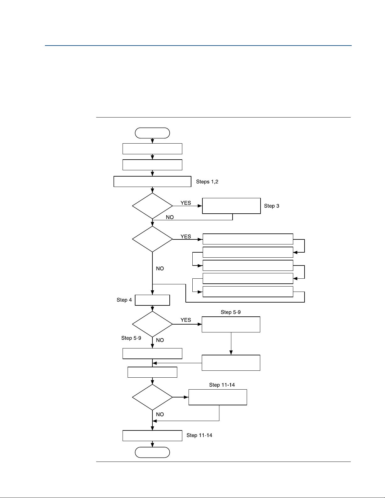
Figure 2-1 is an installation flowchart that provides guidance through the installation process.
Following the figure, an installation checklist has been provided to verify that all critical steps
have been taken in the installation process. The checklist numbers are indicated in the
flowchart.
Figure 2-1. Commissioning Chart
4
Installation
Page 11

Reference Manual
00809-0100-4810, Rev EC
2.2.2 Handling
The product tag is not designed to withstand the weight of the flowmeter - do not lift the
product by the tag.
Do not lift the product by the orifice holes. Holes have sharp edges that may cause personal
injury. Lift the product by the neck tube connecting the orifice plate to manifold/transmitter
assembly.
Section 2: Installation
May 2015
2.2.3 Straight run requirements
Table 2-1. 405C Straight Pipe Requirements
Beta 0.40 0.50 0.65
Reducer 2 2 2
Single 90° bend or tee 2 2 2
Two or more 90° bends in the same plane 2 2 2
Two or more 90° bends in different planes 2 2 2
Up to 10° of swirl 2 2 2
Butterfly valve (75% to 100% open) 2 5 5
Upstream (inlet)
side of primary
Downstream (outlet) side of primary
Table 2-2. 405P Straight Pipe Requirements
Beta 0.40 0.50 0.65
Reducer 5 8 12
Single 90° bend or tee 16 22 44
Two or more 90° bends in the same plane 10 18 44
Two or more 90° bends in different planes 50 75 60
Expander 12 20 28
Ball / Gate valve fully open 12 12 18
Upstream (inlet)
side of primary
Downstream (outlet) side of primary
(1)(2)(3) (4)
(1)
(1)(2)
2 2 2
6 6 7
Installation
Table 2-3. 405A Straight Run Requirements
(1)
Without
straightening
With straightening vane
vane
Annubar® averaging pitot tube -
sensor Size 1
Reducer 12 12 8 4
Expander 18 18 8 4
Single 90° bend or tee 8 10 8 4
Two or more 90 ° bends in the same plane 11 16 8 4
Two or more 90° bends in different planes 23 28 8 4
Butterfly Valve (75-100% open) 30 30 8 4
Ball/Gate Valve fully open 8 10 8 4
Upstream (inlet)
side of primary
Downstream (outlet) side of primary
(1) Consult an Emerson Process Management representative if a disturbance is not listed.
(2) If using flow straighteners, refer to ISO 5167 for recommended links.
(3) Use straightening vane to reduce the required straight run length.
(4) In Plane means the Annubar is in the same plane as the elbow. Out of Plane means the bar is perpendicular to
the plane of the upstream elbow. Refer to Figure 2-2 on page 6.
In
plane
Out of
(4)
plane
4 4 4 4
From
(4)
disturbance
From
straightening
vane
(3)
5
Page 12
Section 2: Installation
FLOW
In plane Out of plane
May 2015
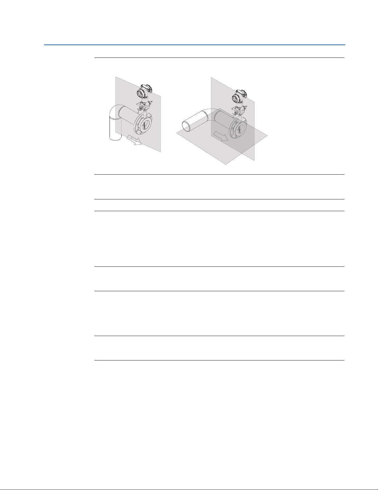
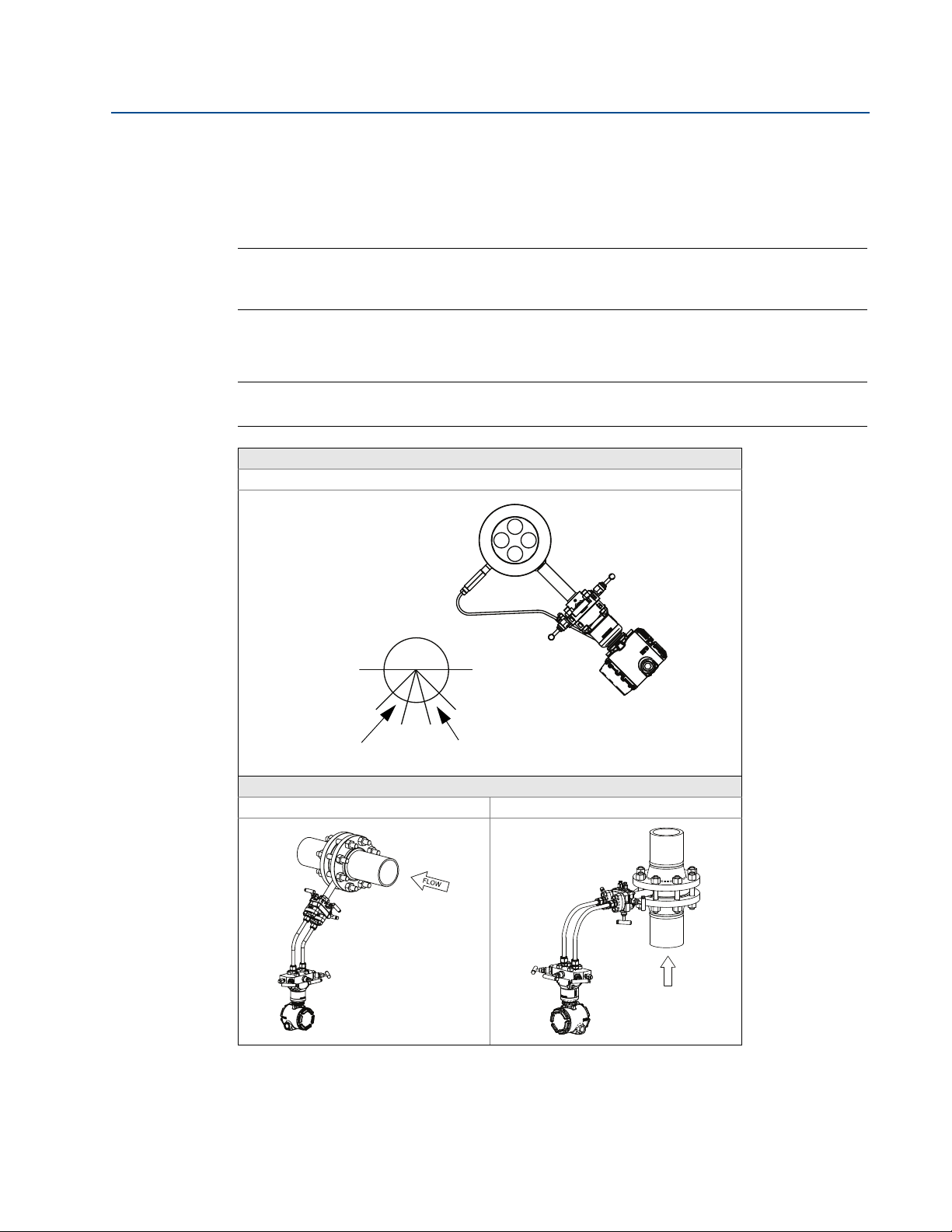
Figure 2-2. Compact Annubar Flowmeter In Plane and Out of Plane
Note
The above figure depicts in plane and out of plane orientations only. Refer to
for recommended straight run requirements
Reference Manual
00809-0100-4810, Rev EC
FLOW
Table 2-3 on page 5
2.2.4 Bolting a transmitter to the Rosemount 405
If the Rosemount 405 is ordered separately from the Rosemount transmitter and will be used in
a direct mount configuration, it will need to be assembled to the transmitter. Follow the
directions below to assemble the 405 to a transmitter with a coplanar configuration.
Note
Units shipped from the factory direct mounted are pressure tested and characterized with the
primary attached. Factory assembly is recommended for best performance.
1. Remove the body bolts (4) from the transmitter.
2. Remove the socket head cap screws from the bottom of the coplanar flange and
remove the coplanar flange.
Note
Protect the transmitter sensing diaphragms and do not remove the O-rings in transmitter
sensor module.
3. Carefully assemble the 405 to the pressure transmitter sensor making sure the “H” and
“L” on transmitter and primary match.
4. Use studs and nuts supplied with the 405 to connect the transmitter sensor to the
manifold head of the 405.
5. Preload to 150 lbs/in. then final torque at 300 lbs/in. Tighten evenly in a cross pattern.
6
Installation
Page 13
Reference Manual
00809-0100-4810, Rev EC
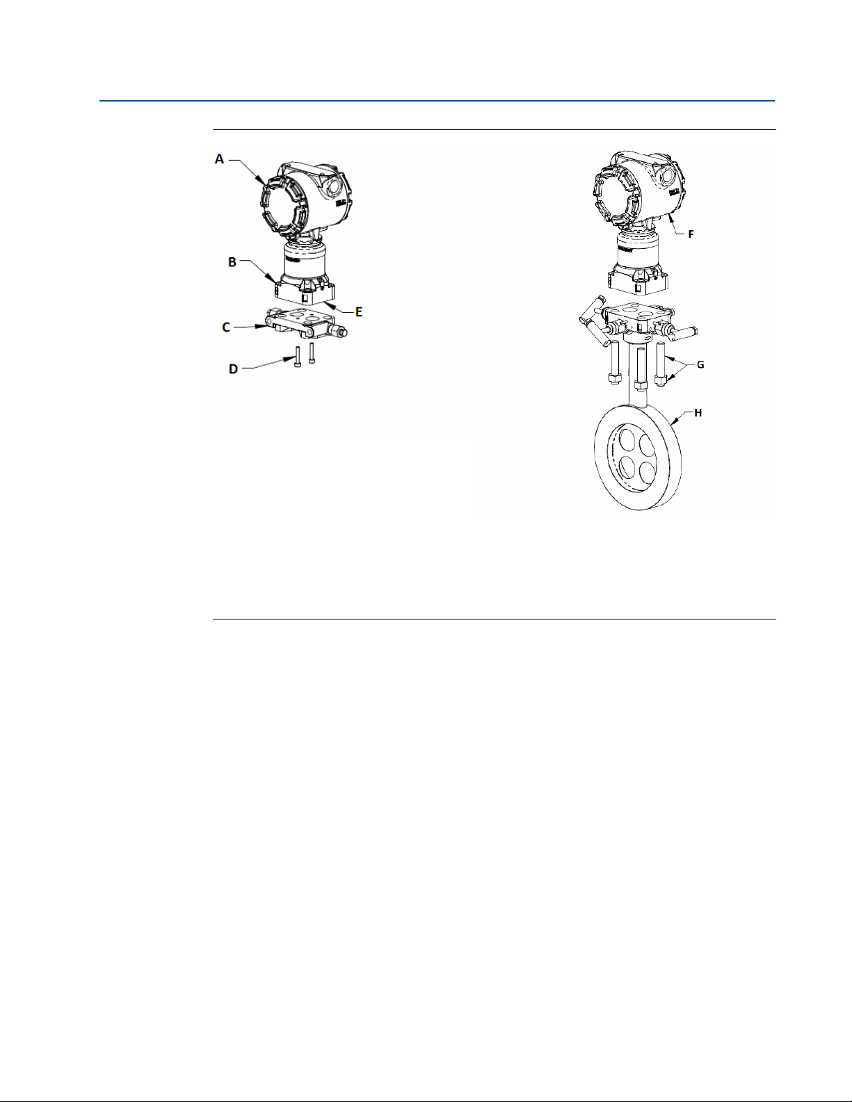
Figure 2-3. Bolting the 405 to a Transmitter
Section 2: Installation
May 2015
A. Transmitter E. Sensing diaphragms and O-rings (do not disturb or remove)
B. Sensing module F. Transmitter
C. Coplanar flange G. Studs and nuts
D. Flange screws H. Rosemount 405
Installation
7
Page 14
Section 2: Installation
30°
Recom mended
Zone 30°
Recommended
Zone 30°
45°
45°
May 2015
2.3 Location and orientation
The primary element can be installed in any position around the circumference of the pipe,
provided the vents are positioned properly for bleeding or venting. Optimal results for liquid in a
vertical line or steam are obtained when flow is up.
Note
The maximum acceptable temperature for direct mounting is 450 °F (232 C°). Refer to
and orientation” on page 8 if the process could potentially exceed this temperature.
2.3.1 Liquid - Rosemount 405C, 405P, and 405A
Note
The 405 should not be used in vertical liquid or steam applications if the fluid is flowing down.
Direct mount
Horizontal liquid
Reference Manual
00809-0100-4810, Rev EC
“Location
Remote mount
Horizontal liquid Vertical liquid
FLOW
Vent location will depend on direction of flow. The vent is fixed to the downstream side.
8
Installation
Page 15

Reference Manual
45°45°
Recom mended
Zone 90°
360°
Flow
FLOW
00809-0100-4810, Rev EC
2.3.2 Gas - Rosemount 405C, 405P, and 405A
Note
Due to drain vent orientation, a direct mount 405 should not be used in vertical gas applications
if the fluid is flowing up. Consider remote mounting the pressure transmitter to facilitate
condensate draining.
Direct mount
Horizontal gas Vertical gas
Section 2: Installation
May 2015
Remote mount
Horizontal gas Vertical gas
Gas in vertical pipes
The Rosemount 405 should be mounted with vents on bottom to allow condensate
drainage.
Installation
9
Page 16

Section 2: Installation
30°
Recom mended
Zone 30°
Recommended
Zone 30°
45°
45°
FLOW
May 2015
2.3.3 Steam - Rosemount 405C, 405P, and 405A
Note
The 405 should not be used in vertical liquid or steam applications if the fluid is flowing down.
Direct mount
Horizontal steam
Reference Manual
00809-0100-4810, Rev EC
Remote mount
Horizontal steam Vertical steam
Note
For the 405A in steam applications, with DP readings in a low flow condition as low as 0.75
inH
O in horizontal pipes consider installing the primary element/flowmeter in the Top
2
Mounting for steam configuration.
10
Installation
Page 17
Reference Manual
60°
60°
Recommended
Zone 60°
00809-0100-4810, Rev EC
2.3.4 Top mounting for steam
Top mounting in steam is an alternative mounting method for steam installations that can be
used if there are space restrictions or other concerns. This installation method is intended for
applications that run with limited interruptions or shutdowns. Also, for outdoor applications,
top mounting can eliminate the need for heat tracing, if steam is flowing.
Direct mount - 405C, 405P, and 405A
Horizontal top mounting for steam up to 400 °F (204 °C)
Note
For the 405A in wet steam applications, do not mount the flowmeter at the direct vertical
position. Mounting at an angle will avoid measurement inaccuracy due to water running
along the bottom of the pipe.
Section 2: Installation
May 2015
Remote mount up to 850 °F (454 °C) - 405C, 405P, and 405A
Note
When top mounting with a remote mount transmitter, use enough impulse piping to dissipate
the process heat to avoid damaging the transmitter.
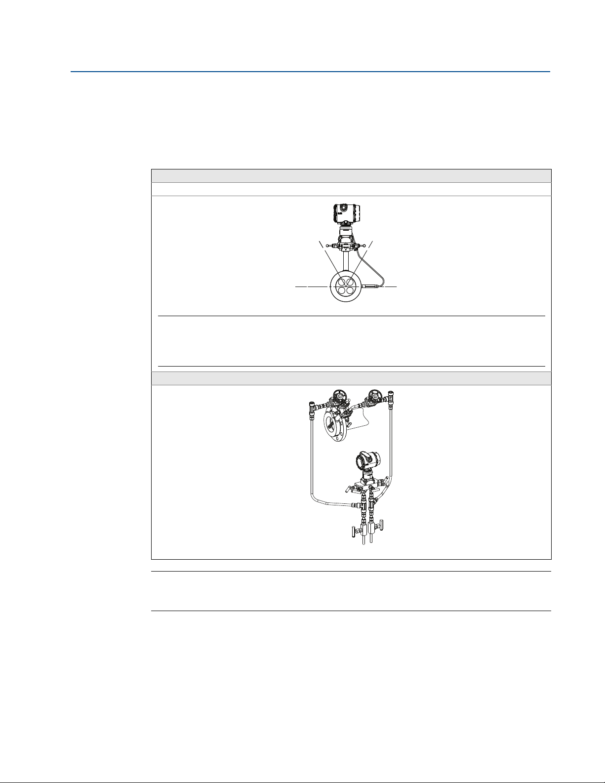
Suggested top mounting orientations: For steam up to 400 °F (204 °C) use direct mount
orientation and for steam up to 850 °F (454 °C) use remote mount orientation. For direct
mounting, ambient temperature should be less than 100 °F (38 °C). For remote mount
installations, the impulse piping should slope up slightly from the instrument connections on
the 405A Compact Annubar primary element to the cross fittings, allowing condensate to drain
back into the pipe. From the cross fittings, the impulse piping should be routed downward to
Installation
11
Page 18

Section 2: Installation
May 2015
the transmitter and the drain legs. The transmitter should be located below the instrument
connections of the 405A Compact Annubar primary element.
For technologies C, P, and A, depending on the environmental conditions, it may be necessary
to insulate the mounting hardware.
2.3.5 Process connections (remote mount only)
The 405 is available with either ¼-in. – 18 NPT connections (standard) or 1/2-in. – 14 NPT
connections (option code E)
centers of 2-in. (51 mm), 2
lubricant or sealant when making the process connections.
Ensure all four flange studs are installed and tightened prior to applying pressure to prevent
process leakage. When properly installed, the flange studs will protrude through the top of the
module housing.
Note
Do not attempt to loosen or remove the flange studs while the 405 is in service.
(1)
. The 1/2-in. connections can be rotated to attain connection
1
/8-in. (54 mm), or 2 1/4-in. (57 mm). The threads are Class 2; use a
Reference Manual
00809-0100-4810, Rev EC
Perform the following to install flange adapters to the head of the 405.
1. Place O-ring in the groove on bottom of the flange adapter.
2. Position flange adapters over NPT connections on the adapter plate.
3. Insert studs through 405 head, adapter plate, and flange adapters.
4. Thread nuts onto studs. Tighten nuts to 300 in-lbs. (34 N-m).
(1) The Rosemount 405A is only available with 1/2-in. - 14 NPT connections for remote mount transmitter connections.
12
Installation
Page 19
Reference Manual
00809-0100-4810, Rev EC
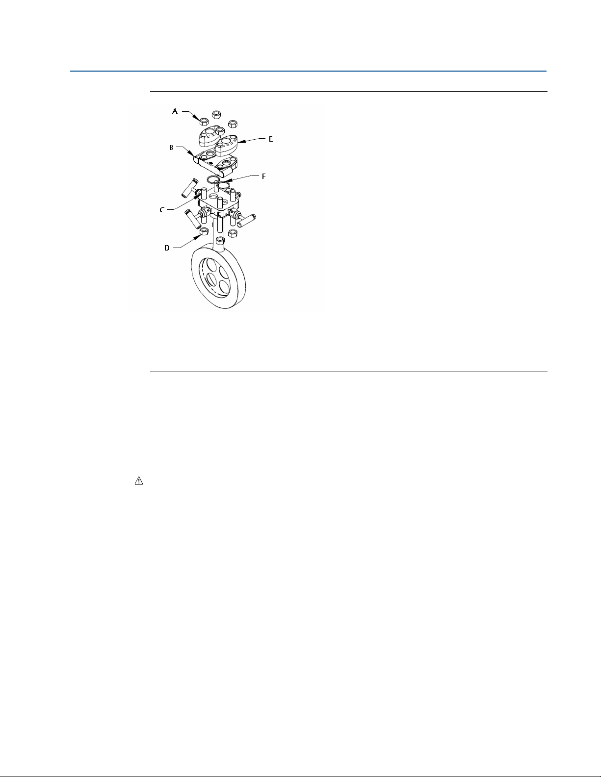
Figure 2-4. Installing the Flange Adapters to a 405
Section 2: Installation
May 2015
A. Nut D. Nut
B. Adapter plate E. Flange adapter
C. Stud F. O -R ing
When compressed, PTFE O-rings tend to cold flow, which aids in their sealing capabilities. When
removing adapter plates or adapters, visually inspect the O-rings. Replace them if there are any
signs of damage, such as nicks or cuts. If they are undamaged, you may reuse them. If you
replace the O-rings, retorque the nuts after installation to compensate for cold flow.
High temperature units (option code T)
Alloy O-rings should be replaced any time the unit is disassembled.
Installation
13
Page 20

Section 2: Installation
May 2015
2.4 405 installation
Install the 405 according to the procedure below.
Reference Manual
00809-0100-4810, Rev EC
1. Orient the assembly according to the guidelines provided in
page 8
. Ensure the flow arrow is pointing in the same direction as the process flow.
“Location and orientation” on
Note
An ANSI alignment ring is provided standard with the 405. If a DIN or JIS alignment ring is
required, it must be ordered as an option. Contact an Emerson Process Management sales
representative for additional information.
Note
For ease of installation, the gasket may be secured to the flange face with small pieces of tape.
Be sure the gasket and/or tape do not protrude into the pipe.
2. If using an alignment ring with through holes, proceed to
Step 9.
3. Insert two studs through the flange holes located opposite the head of the 405.
4. Place the alignment ring on the 405 body (see
Figure 2-5).
5. Insert gaskets.
6. Insert the 405 between the flanges so that the indentations on the alignment ring
contact the installed studs. The studs must contact the alignment ring in the
indentation marked with the appropriate flange rating to ensure proper alignment.
7. Install remaining studs and nuts (hand tight). Ensure that three of the studs are in
contact with the alignment ring.
8. Lubricate studs and tighten nuts in a cross pattern to the appropriate torque per local
standards.
Note
Step 9 through Step 12 are for use with alignment rings that have through holes.
9. Place the alignment ring on the 405 body (see
Figure 2-5).
10. Insert the 405 between the flanges. Insert one stud through the flange hole located
opposite the 405 head; passing through the alignment ring through hole and the
opposite flange hole. The stud must contact the alignment ring through the through
hole marked with the appropriate flange rating to ensure proper alignment.
11. Repeat
Step 10 for a second (2) stud opposite the 405 head.
12. Insert gaskets.
13. Install remaining studs and nuts (hand tight). Ensure that three of the studs are in
contact with the alignment ring.
14. Lubricate studs and tighten nuts in a cross pattern to the appropriate torque per local
standards.
14
Installation
Page 21

Reference Manual
00809-0100-4810, Rev EC
Section 2: Installation
May 2015
Note
Standard
1
/16-in. gaskets are recommended for use with the 405. Using other gaskets could
potentially caused a bias shift in the measurement.
2.4.1 Recommended insulation guidelines
For Flowmeters with integral temperature assembly:
It is recommended for the meter to be insulated when the process ambient temperature is
greater than 30 °F (-1 °C).
1. For line sizes
(100 mm) of insulation of at least a 4.35 R-factor.
2. For line sizes 6-in. (150 mm) to 12-in. (300 mm), it is recommended to have 5-in.
(125 mm) of insulation of at least a 4.35 R-factor.
The full thickness stated above may not be necessary for the entire flowmeter, but is required
for the temperature sensor area at a minimum. Insulation is needed to ensure meeting our
specified temperature measurement accuracy.
Figure 2-5. 405 Installation
1
/2-in. (15 mm) to 4-in. (100 mm), it is recommended to have 4-in.
Installation
(1)
A. 405
B. Alignment Ring G. 405
C. Existing Pipe Assembly with Flange H. Transmitter
D. Nut I. Stud
E. (2) Gasket
(1) This installation drawing applies to the 405C, 405P, and 405A.
(2) The installation drawing applies when using the Rosemount 3051S, Rosemount 3051S MultiVariable,
Rosemount 3051, and Rosemount 2051 Transmitter. See the following documents for quick installation
instruction of the transmitters:
Rosemount 3051S MultiVariable Transmitter: document number 00825-0100-4803
Rosemount 3051S: document number 00825-0100-4801
Rosemount 3051: document number 00825-0100-4001
Rosemount 2051: document number 00825-0100-4101
F. Alignment Ring
(1)
(2)
15
Page 22

Section 2: Installation
May 2015
2.4.2 Remote RTD installation
A remote RTD requires that the process piping be modified. Follow site specific requirements for
installation. Install the RTD thermowell in close proximity downstream
element. The standard supplied RTD connection cable is 12 ft long. Consult factory for longer
lengths.
5
Drill a
/8-in. (16 mm) to 3/4-in. (19 mm) hole at the RTD location and weld on a customer
supplied 1-in. (25 mm) tall
weld coupling. The thermowell material is 316 SST with
will be inserted 1
1
/2-in. (38 mm) into the pipe internal diameter.
For remote RTD applications with pipe diameters less than 2 inches (50 mm) consult factory.
1
/2 inch -14 NPT weld coupling. The RTD thermowell threads into the
Reference Manual
00809-0100-4810, Rev EC
(1)
of the primary
1
/2–14 ANPT threads. When installed It
(1) For the 405P, at least six pipe diameters downstream of the primary element. For the 405C, two pipe diameters downstream of the primary
element.
16
Installation
Page 23

Reference Manual
00809-0100-4810, Rev EC
Section 3 Commissioning
Safety messages . . . . . . . . . . . . . . . . . . . . . . . . . . . . . . . . . . . . . . . . . . . . . . . . . . . . . . . . . . . . page 17
Direct mount applications . . . . . . . . . . . . . . . . . . . . . . . . . . . . . . . . . . . . . . . . . . . . . . . . . . . page 18
Remote mount applications . . . . . . . . . . . . . . . . . . . . . . . . . . . . . . . . . . . . . . . . . . . . . . . . . . page 21
3.1 Safety messages
Instructions and procedures in this section may require special precautions to ensure the safety
of the personnel performing the operations. Refer to the following safety messages before
performing any operation in this section.
Explosions could result in death or serious injury.
Do not remove the transmitter cover in explosive atmospheres when the circuit is live.
Before connecting a HART
the instruments in the loop are installed in accordance with intrinsically safe or
nonincendive field wiring practices.
Verify that the operating atmosphere of the transmitter is consistent with the
appropriate hazardous locations certifications.
Both transmitter covers must be fully engaged to meet explosion-proof requirements.
®
Communicator in an explosive atmosphere, make sure
Section 3: Commissioning
May 2015
Failure to follow these installation guidelines could result in death or serious injury.
Make sure only qualified personnel perform the installation.
If the line is pressurized, serious injury or death could occur by opening valves.
Commissioning
17
Page 24
Section 3: Commissioning
May 2015
3.2 Direct mount applications
3.2.1 Liquid service
1. Pressurize line.
2. Open the equalizer valve.
3. Open the high and low side valves.
4. Bleed drain/vent valves until no gas is apparent in the liquid.
5. Close the vent/drain valves.
6. Close the low side valve.
7. Check transmitter zero according to the transmitter product manual so that the output
on the test meter reads zero percent of span.
8. Close the equalizer valve.
Reference Manual
00809-0100-4810, Rev EC
9. Open the low side valve. The system is now operational.
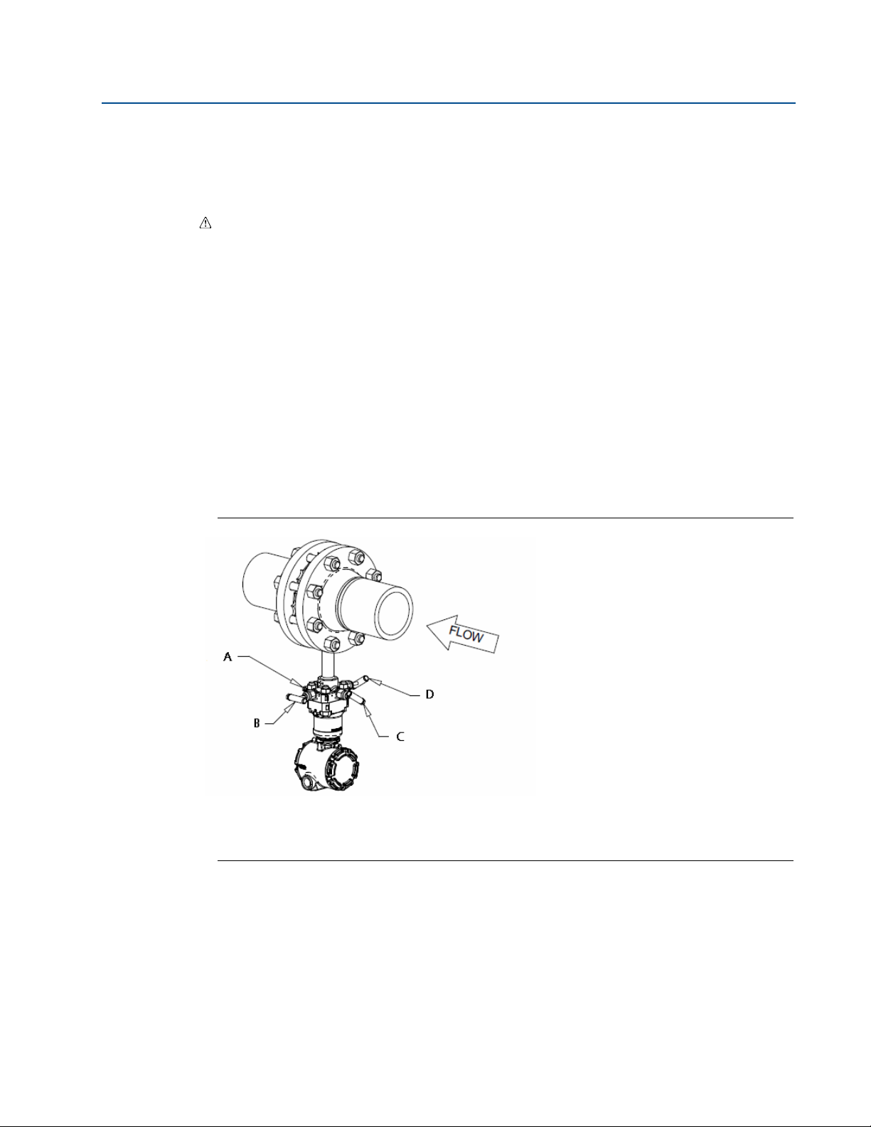
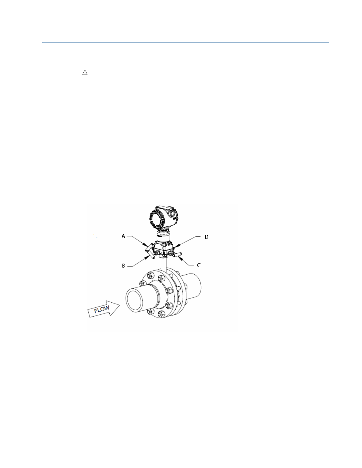
Figure 3-1. Direct Mount Liquid Service
A. (2) Drain/Vent C. Equalizer Valve
B. Low Valve D. High Valve
18
Commissioning
Page 25
Reference Manual
00809-0100-4810, Rev EC
3.2.2 Gas service
1. Pressurize line.
2. Open the equalizer valve.
3. Open the high and low side valves.
4. Open drain/vent valves to ensure no liquid is present.
5. Close the vent/drain valves.
6. Close the low side valve.
7. Check transmitter zero according to the transmitter product manual so the output on
the test meter reads zero percent of span.
8. Close the equalizer valve.
9. Open the low side valve. The system is now operational.
Section 3: Commissioning
May 2015
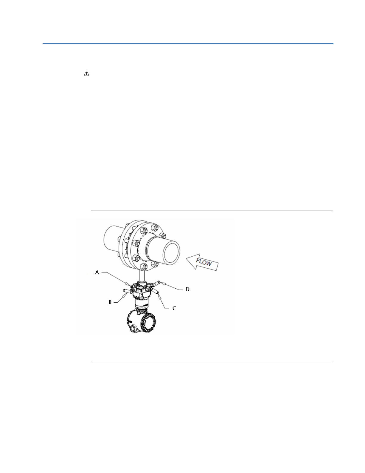
Figure 3-2. Direct Mount Gas Service
A. High Valve C. Low Valve
B. Equalizer Valve D. (2) Drain/Vent
Commissioning
19
Page 26
Section 3: Commissioning
May 2015
3.2.3 Steam service
1. Remove pressure from line.
2. Open equalizer, high, and low side valves.
3. Zero electronics.
4. Fill manifold and transmitter with water via drain vents.
5. Close low side valve to prevent possible heat damage to transmitter.
6. Pressurize line.
7. Gently tap electronics body, manifold head, and 405 body with a small wrench to
dislodge any entrapped air.
8. Zero electronics.
9. Close the equalizer valve. Then open the low side valve.
Reference Manual
00809-0100-4810, Rev EC
10. The system is now operational.
Figure 3-3. Direct Mount Steam Service
A. (2) Drain/Vent C. Equalizer Valve
B. Low Valve D. High Valve
20
Commissioning
Page 27

Reference Manual
00809-0100-4810, Rev EC
3.3 Remote mount applications
3.3.1 Liquid service
1. Zero electronics and pressurize line.
2. Open equalizer valves on transmitter manifold and 405.
3. Open high and low side transmitter manifold valves and 405 valves.
4. Bleed vent valves on transmitter manifold until no air is present.
5. Close vent valves.
6. Close equalizer valve on 405.
7. Check transmitter zero. If transmitter does not read zero repeat Step 1 through Step 7.
8. Close equalizer valve on transmitter manifold.
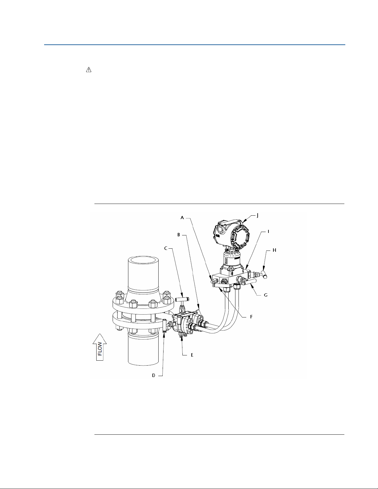
Figure 3-4. Remote Liquid Service
Section 3: Commissioning
May 2015
Commissioning
A. Vents F. Transmit ter
B. 405 High Valve G. Manifold Low Valve
C. Transmitter Manifold H. Manifold Vent
D. Manifold High Valve I. 405 Equalizer Valve
E. Manifold Equalizer Valve J. 405 Low Valve
21
Page 28
Section 3: Commissioning
May 2015
3.3.2 Gas service
1. Zero electronics and pressurize line.
2. Open equalizer valves on transmitter manifold and 405.
3. Open high and low side transmitter manifold valves and 405 valves.
4. Open drain/vent valves on transmitter manifold to ensure no liquids are present.
5. Close drain/vent valves.
6. Close low side transmitter manifold valve.
7. Close 405 equalizer valve.
8. Check transmitter zero. If transmitter does not read zero repeat Step 1 through Step 7.
9. Close equalizer on transmitter manifold.
10. Open low side valve on transmitter manifold. The system is now operational.
Reference Manual
00809-0100-4810, Rev EC
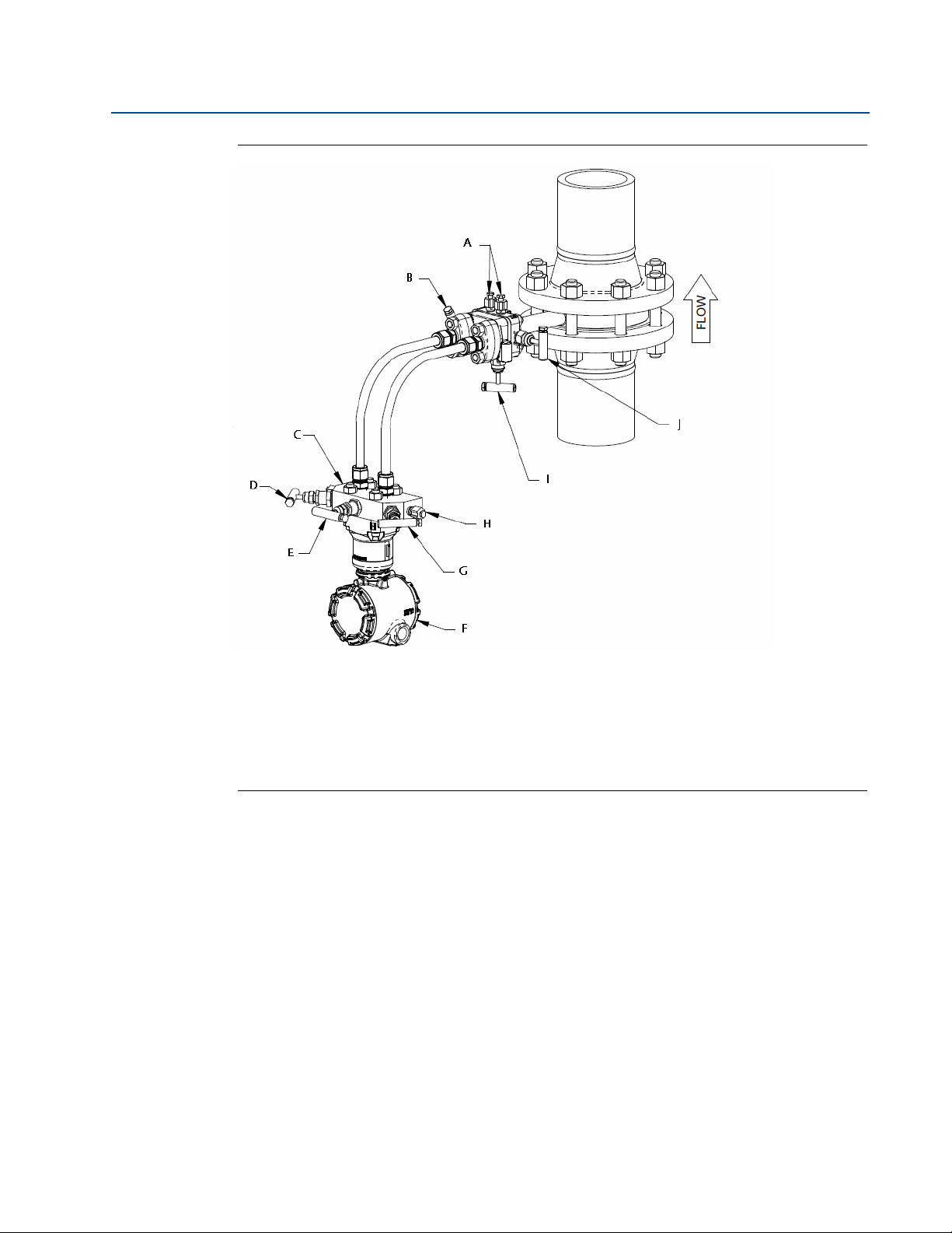
Figure 3-5. Remote Gas Service
A. Manifold Vents F. Manifold High Valve
B. 405 Low Valve G. Manifold Equalizer Valve
C. 405 Equalizer Valve H. Manifold Low Valve
D. 405 High Valve I. Transmitter Manifold
E. Drain/Vents J. Transmitter
22
Commissioning
Page 29

Reference Manual
00809-0100-4810, Rev EC
3.3.3 Steam service
1. Remove pressure from line.
2. Open equalizer valves, high side valves, and low side valves on both the 405 and
transmitter manifold.
3. Zero electronics.
4. Fill transmitter manifold, instrument lines, and 405 with water via drain vents on
transmitter manifold.
5. Close 405 equalizer valve and transmitter manifold vents.
6. Close low side transmitter manifold valve.
7. Pressurize line.
8. Gently tap electronics body, transmitter manifold, instrument lines, and 405 with a
small wrench to dislodge any trapped air.
Section 3: Commissioning
May 2015
9. Check transmitter zero. If transmitter does not read zero repeat Step 4 through Step 8.
10. Close the transmitter equalizer and open low side valve on transmitter manifold. The
system is now operational.
Commissioning
23
Page 30
Section 3: Commissioning
May 2015
Figure 3-6. Remote Steam Service
Reference Manual
00809-0100-4810, Rev EC
A. Drain/Vents F. Tran smitter
B. 405 High Valve G. Manifold Low Valve
C. Transmitter Manifold H. Manifold Vent
D. Manifold High Valve I. 405 Equalizer Valve
E. Manifold Equalizer Valve J. 405 Low Valve
24
Commissioning
Page 31

Reference Manual
00809-0100-4810, Rev EC
Section 4: Operation and Maintenance
Section 4 Operation and Maintenance
Safety messages . . . . . . . . . . . . . . . . . . . . . . . . . . . . . . . . . . . . . . . . . . . . . . . . . . . . . . . . . . . . page 25
Troubleshooting . . . . . . . . . . . . . . . . . . . . . . . . . . . . . . . . . . . . . . . . . . . . . . . . . . . . . . . . . . . . page 26
RTD maintenance . . . . . . . . . . . . . . . . . . . . . . . . . . . . . . . . . . . . . . . . . . . . . . . . . . . . . . . . . . . page 28
4.1 Safety messages
Procedures and instructions in this section may require special precautions to ensure the safety
of the personnel performing the operations. Information that raises potential safety issues is
indicated by a warning symbol ( ). Refer to the following safety messages before performing
an operation preceded by this symbol.
May 2015
Explosions can result in death or serious injury.
Do not remove the instrument cover in explosive environments when the circuit is live.
Both transmitter covers must be fully engaged to meet
explosion-proof requirements.
Before connecting a communicator in an explosive atmosphere, make sure the
instruments in the loop are installed in accordance with intrinsically safe or
nonincendive field wiring practices.
Electrical shock can result in death or serious injury.
Avoid contact with the leads and the terminals.
Operation and Maintenance
25
Page 32

Section 4: Operation and Maintenance
May 2015
Reference Manual
00809-0100-4810, Rev EC
4.2 Troubleshooting
If a malfunction is suspected despite the absence of a diagnostic messages on the
communicator display, follow the procedures described below to verify that the flowmeter
hardware and process connections are in good working order. Always approach the most likely
and easiest-to-check conditions first.
Symptom Possible cause Corrective action
Questionable accuracy
Improper installation
or erroneous flow signal
System leaks Check for leaks in instrument piping. Repair and seal all leaks.
Contamination/plugging Remove the flowmeter and check for contamination.
Closed valve Verify that both Rosemount transmitter (PH & PL) or (MH &
Calibration Is the calibration too high or low for the flow rate?
Connections (remote mount
only)
Entrapped air (liquid
applications)
Rosemount transmitter
misalignment
Operating conditions Are the operating conditions in compliance with those given at
Spiking flow signal Two-phase flow The flowmeter is a head measurement device and will not
Spiking flow signal
(Stream Service)
Improper insulation (vertical
pipes only)
Excessive vibration
Milliamp reading is zero No flow in system.
Power polarity
Electronics not in
Power supply
communication
Milliamp reading is low
Zero Trim
or high
No response to changes
in applied flow
Blocked upstream piping
and/or blocked impulse piping
Is the flow arrow pointed in the direction of the flow?
Verify the cross reservoirs are perfectly level with one
another.
Is there sufficient straight run upstream and downstream of
the flowmeter?
ML) valves are open. Verify that vent, equalizer, and line valves
are properly positioned per the “start up procedure.”
Verify that the high side of the electronics is connected to the
high side of the flowmeter. Check the same for the low side.
Are there uneven water legs caused by air entrapment in the
instrument connections? If so, bleed air.
Misalignment of the flowmeter beyond 3 degrees will cause an
erroneous signal.
the time the flowmeter was purchased? Check the flow
calculation and the fluid parameters for accuracy.
Double-check pipe inside diameter for proper sizing.
accurately measure a two-phase flow.
Added insulation may be required to ensure that a phase
change occurs at the cross reservoirs.
Check the impulse piping for vibration.
Check if power polarity is reversed
Verify voltage across terminals (should be 10–55V dc)
Check for bad diode in terminal block
Replace electronics terminal block
Check power supply voltage at electronics (10.5V minimum)
Check load resistance (250 ohms minimum)
Check if unit is addressed properly
Replace electronics board
Check pressure variable reading for saturation
Check if output is in alarm condition
Perform 4–20 mA output trim
Replace electronics board
Check test equipment
Check impulse piping for blockage
Check for disabled span adjustment
Check electronics security switch
Verify calibration settings (4 and 20 mA points)
Contact factory for replacement
26
Operation and Maintenance
Page 33

Reference Manual
00809-0100-4810, Rev EC
Symptom Possible cause Corrective action
Low reading/high
reading
Erratic reading for
pressure variable
Blocked upstream piping
and/or blocked impulse piping
Blocked upstream piping
and/or blocked impulse piping
Check impulse piping for blockage
Check test equipment
Perform full sensor trim (if software revision is 35 or higher)
Contact factory for replacement
Check impulse piping for blockage
Check damping
Check for EMF interference
Contact factory for replacement
Check flow direction
Check that the flow arrow on the neck of the 405 points in the direction of flow. If the DP
transmitter is remote mounted from the 405, be sure that the impulse tubing is connected
correctly from the 405 to the DP transmitter (high to high and low to low).
Check orientation
Section 4: Operation and Maintenance
May 2015
Improper orientation can result in inaccurate measurements.
Check zero
The transmitter may read off in the high or low direction if not zeroed properly at start-up/commissioning. Refer to the appropriate transmitter reference manual for additional information.
Check valves
The correct valve setting for flow measurement are; equalizer valve fully closed, high and low
side valves fully open.
Check configuration/scaling
Is the 20mA DP URL of the 405 set properly? This may involve sizing the 405 in the Toolkit
Software program to confirm.
Confirm the DCS or PLC and transmitter on 405 are scaled consistently.
Is the square root being taken in the DCS or transmitter attached to the 405? The square root
should not be taken in both places.
Check Rosemount Pressure Transmitter configuration
If a Rosemount Pressure Transmitter is being used, its enhanced functionality should be taken
into account during configuration and troubleshooting. The square root should not be taken in
the DCS if a 3051S MultiVariable Transmitter is being used.
See the Rosemount Pressure Transmitter Reference manuals for additional information.
Rosemount 3051S MultiVariable Reference Manual is document number 00809-0100-4803.
Rosemount 3051 Pressure Transmitter Reference Manual is document number
00809-0100-4001. Rosemount 2051 Pressure Transmitter Reference Manual is document
number 00809-0100-4101.
Operation and Maintenance
27
Page 34

Section 4: Operation and Maintenance
May 2015
4.3 RTD maintenance
4.3.1 Replacing an RTD
Direct mount - Compact Annubar
If an RTD needs to be replaced on a direct mounted Compact Annubar Flowmeter, proceed as
follows:
1. Close instrument valves to ensure the pressure is isolated from the transmitter.
2. Open the bleed valves on the transmitter to remove all pressure.
3. Remove cap and RTD wiring only from temperature housing and from the transmitter.
4. Remove transmitter.
5. Remove RTD plug.
Reference Manual
00809-0100-4810, Rev EC
6. Pull RTD wire out of the nipple and remove RTD. Remove RTD by inserting the wires
through a
7
/16-in. deep socket. Then use pliers or vise grips to rotate the socket. The RTD
is in a thermowell. No live line pressure will be present.
7. Install new RTD and thread finger tight plus
1
/8 of a turn. Thread wires through the
nipple. Note it may be easier to remove the terminal block from the temperature
housing to reinsert the RTD wires.
8. Using appropriate thread lubricant, reinstall the
1
/2-in. NPT plug.
9. Use the same PTFE gaskets to reinstall the transmitter to the Annubar Flowmeter sensor
head.
10. Use a torque wrench to tighten the stainless steel hex nuts in a cross pattern to 300
in-lbs.
11. Reconnect RTD wires in the temperature housing and replace cover.
12. Open instrument valves.
28
Operation and Maintenance
Page 35

Reference Manual
B
C
E
D
A
00809-0100-4810, Rev EC
Figure 4-1. Exploded View of Direct Mounted Annubar, Integral RTD Installation
Section 4: Operation and Maintenance
May 2015
A. RTD Plug
B. 1/4” MNPT RTD
C. 1/4” MNPT Close Nipple
D. 1/4” FNPT x 1/2” MNPT Adapter
E. Temperature Housing
Remote mount- Compact Annubar
If an RTD needs to be replaced on a remote mounted Compact Annubar Flowmeter, proceed as
follows:
1. Close instrument valves to ensure that the pressure is isolated from the transmitter.
2. Open bleed valves on transmitter to remove all pressure.
3. Remove cap from temperature housing.
4. Remove RTD wiring from terminal block.
5. Remove temperature housing from head.
6. Pull RTD wire out of nipple and remove RTD. The RTD is in a thermowell. No live line
pressure will be present.
7. Install new RTD and thread wires through the nipple.
8. Using appropriate thread lubricant or tape, install terminal housing onto remote head.
9. Reconnect RTD wires to the terminal.
10. Open instrument valves.
Operation and Maintenance
29
Page 36

Section 4: Operation and Maintenance
A
C
B
J
H
I
E
G
D
F
May 2015
Remote mount for compact conditioning and standard orifice
If an RTD needs to be replaced on a remote mount Rosemount 405 with primary element
technology P and C, proceed as follows:
1. Close instrument valves to ensure the pressure is disconnected from the transmitter.
2. Open bleed valves on the transmitter to remove all pressure.
3. Remove cap.
4. Remove RTD wiring only from terminal.
5. Remove terminal housing from the head.
6. Pull RTD wire out of nipple and remove RTD. The RTD is in a thermowell, so no live line
pressure will be present.
7. Install new RTD and thread wires through the nipple.
8. Using appropriate thread lubricant or tape, install terminal housing onto remote head.
Reference Manual
00809-0100-4810, Rev EC
9. Reconnect RTD wires to terminal. This diagram is for a typical RTD transmitter wiring
connection.
10. Open instrument valves.
A. Rubber Bushing (Slide stop to edge of armored cable) F. C ap
B. Compression Fitting G. Bushing
C. 3/4 to 1/2–in. NPT Adapter (Screws into RTD Connection Head) H. Compression
D. Washer I. Fitting
E. Cap J. Connect to transmitter
30
Operation and Maintenance
Page 37

Reference Manual
00809-0100-4810, Rev EC
Section 4: Operation and Maintenance
May 2015
4.3.2 Direct mount for compact conditioning and standard orifice
If an RTD needs to be replaced on a direct mount Rosemount Integrated Orifice Flowmeter,
proceed as follows:
Note
RTD wires are specifically bent for each unit, contact Rosemount for replacement RTD cable
prior to disassembling the unit.
1. Close instrument valves to ensure that the pressure is disconnected from the
transmitter.
2. Open the bleed valves on the transmitter to remove all pressure.
3. Remove the cap.
4. Remove the RTD wiring only from the terminal.
5. Unscrew the union adapter from the transmitter's conduit entry.
6. Unscrew the hex compression fitting from the 405 Orifice Plate and remove the RTD
and metal wire from the unit. Remove the union adapter and hex compression fitting
from RTD cable.
7. With the terminal block facing the user, thread the male half of the union adapter into
the transmitter's left conduit entry, wrench tight.
8. Thread the hex compression fitting into the side of the 405 orifice plate, tighten to
250 lbs.
9. Insert the new RTD into the compression fitting until it bottoms out.
10. Tighten the plug on top of the compression fitting, wrench tight.
11. Attach the female end of the union adapter to the wire end of the RTD, wrench tight.
12. Run the wires into the conduit entry and connect both halves of the union fitting
together with the coupling nut, wrench tight.
13. Reconnect the RTD wires to the terminal. This diagram is for a typical RTD transmitter
wiring connection.
14. Open the instrument valves.
4.3.3 Electrical RTD check procedure
If the RTD is not functioning properly, perform the following checks to determine if the RTD is
functioning properly. Figure 4-2 shows the schematic of a 4-wire RTD.
Operation and Maintenance
31
Page 38

Section 4: Operation and Maintenance
Red
Red
White
White
May 2015
Continuity check
1. Using an Ohm meter or a multimeter, check the resistance between each of the red and
white wires.
2. If the resistance measured represents the proper temperature, proceed to the
Grounding check .
3. If the resistance measured does not represent the proper temperature or no resistance
is measured (i.e. Open circuit), the RTD is damaged and must be replaced.
Grounding check
1. Using an Ohm meter or a Multimeter, test for each wire of the RTD to the sheath for a
resistance value. If the RTD is installed in the Annubar sensor, test to the instrument
connections of Annubar instead of the sheath of the RTD. All tests should measure an
infinite resistance (i.e. Open circuit) between the RTD wires and the sheath.
2. If all tests verify an open circuit, the RTD is functioning properly.
Reference Manual
00809-0100-4810, Rev EC
3. If any tests confirm a shorted wire to the RTD sheath, the RTD is damaged and must be
replaced.
Figure 4-2. Schematic of a Typical 4-Wire RTD
This section covers RTD maintenance procedures.
32
Operation and Maintenance
Page 39

Reference Manual
00809-0100-4810, Rev EC
Appendix A: Reference Data
Appendix A Reference Data
Ordering information . . . . . . . . . . . . . . . . . . . . . . . . . . . . . . . . . . . . . . . . . . . . . . . . . . . . . . . . . . . . . . . . page 33
Specifications . . . . . . . . . . . . . . . . . . . . . . . . . . . . . . . . . . . . . . . . . . . . . . . . . . . . . . . . . . . . . . . . . . . . . . . page 90
Dimensional drawings . . . . . . . . . . . . . . . . . . . . . . . . . . . . . . . . . . . . . . . . . . . . . . . . . . . . . . . . . . . . . . . page 97
Rosemount 405 Compact Orifice Primary Element . . . . . . . . . . . . . . . . . . . . . . . . . . . . . . . . . . . . . . page 100
Spare parts . . . . . . . . . . . . . . . . . . . . . . . . . . . . . . . . . . . . . . . . . . . . . . . . . . . . . . . . . . . . . . . . . . . . . . . . . page 102
A.1 Ordering information
Table A-1. Rosemount 3051SFC Compact Flowmeter Ordering Information
★ The Standard offering represents the most common options. The starred options (★) should be selected for best delivery.
The Expanded offering is subject to additional delivery lead time.
Measurement
typ e
Model Product description
3051SFC Compact Flowmeter
Transmitter feature board measurement type
D 1-7
• •
May 2015
• = Available
— = Unavailable
1
Tem pe ra tu re
2 Compensated Flow Calculations – Differential & Static Pressures
3 Compensated Flow Calculations – Differential Pressure & Temperature
4 Compensated Flow Calculations – Differential Pressure
D Differential Pressure
Process Variables Only (No Flow Calculations) – Differential & Static Pressures with
Fully Compensated Mass & Energy Flow Calculations – Differential & Static Pressure w/
5
Tem pe ra tu re
6 Process Variables Only (No Flow Calculations) – Differential & Static Pressures
7 Process Variables Only (No Flow Calculations) – Differential Pressure & Temperature
Primary element technology
A Annubar® Averaging Pitot Tube
C Conditioning Orifice Plate
P Orifice Plate
Material type
S 316 SST
Line size
(1)
005
(1)
010
(1)
015
020 2-in. (50 mm)
030 3-in. (80 mm)
040 4-in. (100 mm)
1
/2-in. (15 mm)
1-in. (25 mm)
11/2-in. (40 mm)
— • ★
— • ★
— • ★
— • ★
• — ★
— •
— •
— •
• • ★
• • ★
• • ★
• • ★
• • ★
• • ★
• • ★
• • ★
• • ★
• • ★
Reference Data
33
Page 40

Appendix A: Reference Data
May 2015
Reference Manual
00809-0100-4810, Rev EC
Table A-1. Rosemount 3051SFC Compact Flowmeter Ordering Information
★ The Standard offering represents the most common options. The starred options (★) should be selected for best delivery.
The Expanded offering is subject to additional delivery lead time.
Line size
060 6-in. (150 mm)
080 8-in. (200 mm)
(2)(3)
100
120
(2)(3)
10-in. (250 mm)
12-in. (300 mm)
Primary element type
N000 Annubar Sensor Size 1
N040 0.40 Beta Ratio ()
N050 0.50 Beta Ratio ()
(4)
N065
0.65 Beta Ratio ()
Temperature measurement
(6)
T
(5)
0
(6)
R
Integral RTD
No Temperature Sensor
Remote Thermowell and RTD
Transmitter connection platform
3 Direct-mount
7 Remote-mount, NPT Connections
Differential pressure range
• • ★
• • ★
• • ★
• • ★
• • ★
• • ★
• • ★
• • ★
D 1-7
— • ★
• • ★
• •
• • ★
• • ★
1 0 to 25 inH2O (0 to 62.3 mbar)
2 0 to 250 inH2O (0 to 623 mbar)
3 0 to 1000 inH2O (0 to 2.5 bar)
Static pressure range
(7)
A
None
D Absolute 0 to 800 psia (0 to 55.2 bar)
(8)
E
Absolute 0 to 3626 psia (0 to 250 bar)
J Gage -14.2 to 800 psig (-0.979 to 55.2 bar)
(8)
K
Gage -14.2 to 3626 psig (-0.979 to 250 bar)
Transmitter output
A 4–20 mA with digital signal based on HART® protocol
(9)
F
(10)(11)
X
FOUNDATION™ fieldbus protocol
Wireless
• • ★
• • ★
• • ★
• • ★
— • ★
— • ★
— • ★
— • ★
• • ★
• — ★
• — ★
34
Reference Data
Page 41

Reference Manual
00809-0100-4810, Rev EC
Appendix A: Reference Data
Table A-1. Rosemount 3051SFC Compact Flowmeter Ordering Information
★ The Standard offering represents the most common options. The starred options (★) should be selected for best delivery.
The Expanded offering is subject to additional delivery lead time.
Transmitter housing style Material
Conduit entry size
May 2015
00 None (customer-supplied electrical connection)
1A PlantWeb® Housing Aluminum1/2-14 NPT
1B PlantWeb Housing Aluminum M20 x 1.5
1J PlantWeb Housing SST
1
/2-14 NPT
1K PlantWeb Housing SST M20 x 1.5
2A Junction Box Housing Aluminum1/2-14 NPT
2B Junction Box Housing Aluminum M20 x 1.5
• — ★
• • ★
• • ★
• • ★
• • ★
• — ★
• — ★
Junction Box housing with output for remote
2E
display and interface Aluminum1/2-14 NPT
• — ★
Junction Box housing with output for remote
2F
2J Junction Box Housing SST
2M
(12)
5A
(12)
5J
(10)(13)
7J
1C PlantWeb Housing Aluminum G1/2
1L PlantWeb Housing SST G1/2
2C Junction Box Housing Aluminum G1/2
display and interface Aluminum M20 x 1.5
1
/2-14 NPT
Junction Box housing with output for remote
display and interface SST
1
/2-14 NPT
Wireless PlantWeb housing Aluminum1/2-14 NPT
Wireless PlantWeb housing SST
1
/2-14 NPT
Quick Connect (A size Mini, 4-pin male termination)
• — ★
• — ★
• — ★
• — ★
• — ★
• — ★
• •
• •
• —
Junction Box housing with output for remote
2G
display and interface Aluminum G1/2
• —
Transmitter performance cla ss D 1-7
3051S MultiVariable™SuperModule, Measurement Types 1, 2, 5, and 6
• •
Ultra for Flow: up to 0.75% flow rate accuracy, 14:1 flow turndown, 10-yr stability,
3
5 Classic MV: up to 1.10% flow rate accuracy, 8:1 flow turndown, 5-yr stability
3051S Single Variable SuperModule, Measurement Types 3, 4, 7, and D
limited 12-yr warranty
• • ★
— • ★
• •
Ultra: up to 0.90% flow rate accuracy, 8:1 flow turndown, 10-yr stability, limited 12-yr
1
2 Classic: up to 1.40% flow rate accuracy, 8:1 flow turndown, 5-yr stability
(14)
3
warranty
Ultra for Flow: up to 0.75% flow rate accuracy, 14:1 flow turndown, 10-yr stability,
limited 12-yr warranty
• — ★
• — ★
• • ★
Wireless options (requires option code X and wireless PlantWeb housing)
Update rate, operating frequency, and protocol D 1-7
WA User Configurable Update Rate
Operating frequency and protocol
3 2.4 GHz DSSS, IEC 62591 (WirelessHART®)
Reference Data
• — ★
• — ★
35
Page 42

Appendix A: Reference Data
May 2015
Reference Manual
00809-0100-4810, Rev EC
Table A-1. Rosemount 3051SFC Compact Flowmeter Ordering Information
★ The Standard offering represents the most common options. The starred options (★) should be selected for best delivery.
The Expanded offering is subject to additional delivery lead time.
Omni-directional wireless antenna
WK External Antenna
WM Extended Range, External Antenna
WN High-Gain, Remote Antenna
SmartPower
(15)
1
™
Adapter for Black Power Module (I.S. Power Module Sold Separately)
• — ★
• — ★
• —
• — ★
Other options (include with selected model number)
Extended product warranty D 1-7
WR3 3-year limited warranty
WR5 5-year limited warranty
Installation accessories
A
C
D
G DIN Alignment Ring (PN 16)
H DIN Alignment Ring (PN 40)
J DIN Alignment Ring (PN 100)
B JIS Alignment Ring (10K)
R JIS Alignment Ring (20K)
S JIS Alignment Ring (40K)
ANSI Alignment Ring (150#) (only required for 10-in. (250 mm) and 12-in. (300mm)
line sizes)
ANSI Alignment Ring (300#) (only required for 10-in. (250 mm) and 12-in. (300mm)
line sizes)
ANSI Alignment Ring (600#) (only required for 10-in. (250 mm) and 12-in. (300mm)
line sizes)
Remote adapters D 1-7
• • ★
• • ★
• • ★
• • ★
• • ★
• • ★
• • ★
• • ★
• •
• •
• •
E Flange adapters 316 SST (1/2-in. NPT)
• • ★
High temperature applications
T Graphite Valve Packing (Tmax = 850 °F)
• •
Flow calibration
(16)
WC
WD
(17)(18)
Flow Calibration, 3 Pt, Conditioning Option C (all Pipe Schedules)
Flow Calibration, 10 Pt, Conditioning Option C (all Schedules), Annubar Option A
(Schedule 40)
• •
• •
Pressure testing
P1 Hydrostatic Testing with Certificate
• •
Special cleaning D 1-7
(19)
P2
PA Cleaning per ASTM G93 Level D (section 11.4)
36
Cleaning for Special Processes
• •
• •
Reference Data
Page 43

Reference Manual
00809-0100-4810, Rev EC
Appendix A: Reference Data
Table A-1. Rosemount 3051SFC Compact Flowmeter Ordering Information
★ The Standard offering represents the most common options. The starred options (★) should be selected for best delivery.
The Expanded offering is subject to additional delivery lead time.
Special inspection
May 2015
QC1 Visual & Dimensional Inspection with Certificate
QC7 Inspection & Performance Certificate
• • ★
• • ★
Transmitter calibration certification
Q4 Calibration Data Certificate for Transmitter
QP Calibration Certificate and Tamper Evident Seal
• • ★
• • ★
Quality certification for safety
(20)(21)
QS
(20)(21)(25)
QT
Prior-use certificate of FMEDA data
Safety Certified to IEC 61508 with certificate of FMEDA data
• — ★
• — ★
Material traceability certifications
Q8 Material Traceability Certification per EN 10204:2004 3.1
• • ★
Code conformance
J2 ANSI / ASME B31.1
J3 ANSI / ASME B31.3
J4 ANSI / ASME B31.8
• •
• •
• •
Material conformance
(22)
J5
NACE MR-0175/ISO 15156
• •
Country certification
J1 Canadian Registration
• •
Product certifications D 1-7
E1 AT EX Flam eproof
I1 ATEX Intrinsic Safety
IA ATEX FISCO Intrinsic Safety; for FOUNDATION™ fieldbus protocol only
N1 ATEX Type n
ND ATE X Dust
K1 ATEX Flameproof, Intrinsic Safety, Type n, Dust (combination of E1, I1, N1, and ND)
E4 TIIS Flameproof
E5 FM Explosion-proof, Dust Ignition-proof
I5 FM Intrinsically Safe, Division 2
FM Explosion-proof, Dust Ignition-proof, Intrinsically Safe, Division 2 (combination of
K5
E6
(23)
E5 and I5)
CSA Explosion-proof, Dust Ignition-proof, Division 2
I6 CSA Intrinsically Safe
K6
(23)
CSA Explosion-proof, Dust Ignition-proof, Intrinsically Safe, Division 2 (combination of
E6 and I6)
E7 IECEx Flameproof, Dust Ignition-proof
I7 IECEx Intrinsic Safety
Reference Data
• • ★
• • ★
• — ★
• • ★
• • ★
• • ★
• • ★
• • ★
• • ★
• • ★
• • ★
• • ★
• • ★
• • ★
• • ★
37
Page 44

Appendix A: Reference Data
May 2015
Reference Manual
00809-0100-4810, Rev EC
Table A-1. Rosemount 3051SFC Compact Flowmeter Ordering Information
★ The Standard offering represents the most common options. The starred options (★) should be selected for best delivery.
The Expanded offering is subject to additional delivery lead time.
Product certifications D 1-7
K7
E3 China Flameproof
I3 China Intrinsic Safety
(23)(24)
KA
(23)(24)
KB
(24)
KC
(23)(24)
KD
and N7)
ATEX and CSA Flameproof, Intrinsically Safe, Division 2 (combination of E1, I1, E6, and
I6)
FM and CSA Explosion-proof, Dust Ignition-proof, Intrinsically Safe, Division 2
(combination of E5, E6, I5, and I6)
FM and ATEX Explosion-proof, Intrinsically Safe, Division 2 (combination of E5, E1, I5,
and I1)
FM, CSA, and ATEX Explosion-proof, Intrinsically Safe (combination of E5, E6, E1, I5, I6,
and I1)
• • ★
• • ★
• • ★
• • ★
• • ★
• • ★
• • ★
Shipboard approvals
IECEx Flameproof, Dust Ignition-proof, Intrinsic Safety, Type n (combination of E7, I7,
SBS American Bureau of Shipping
• • ★
Sensor fill fluid and O-ring options D 1-7
L1 Inert Sensor Fill Fluid
L2 Graphite-filled (PTFE) O-ring
LA Inert sensor fill fluid and graphite-filled (PTFE) O-ring
Digital display
(25)
M5 PlantWeb® LCD display
(21)(26)(27)
M7
M8
M9
(21)(26)
(21)(26)
Remote mount LCD display and interface, PlantWeb housing, no cable, SST bracket
Remote mount LCD display and interface, PlantWeb housing, 50 ft. (15m) cable, SST
bracket
Remote mount LCD display and interface, PlantWeb housing, 100 ft. (31m) cable, SST
bracket
• • ★
• • ★
• • ★
• • ★
• • ★
• • ★
• • ★
Transient protection
(28)
T1
Transient terminal block
• • ★
Manifold for remote mount option
F2 3-Valve Manifold, SST
F6 5-Valve Manifold, SST
PlantWeb control functionality
A01 FOUNDATION fieldbus Advanced Control Function Block Suite
PlantWeb diagnostic functionality
D01 FOUNDATION fieldbus Diagnostics Suite
(29)
DA2
Advanced HART Diagnostic Suite
PlantWeb enhanced measurement functionality
(30)
H01
38
FOUNDATION fieldbus Fully Compensated Mass Flow Block
• • ★
• • ★
• — ★
• — ★
• — ★
• — ★
Reference Data
Page 45

Reference Manual
Appendix A: Reference Data
00809-0100-4810, Rev EC
Table A-1. Rosemount 3051SFC Compact Flowmeter Ordering Information
★ The Standard offering represents the most common options. The starred options (★) should be selected for best delivery.
The Expanded offering is subject to additional delivery lead time.
Cold temperature
May 2015
BRR -60 °F (-51 °C) Cold Temperature Start-up
Alarm limit
(20)(21)
C4 NAMUR Alarm & Saturation Levels, High Alarm
C5 NAMUR Alarm & Saturation Levels, Low Alarm
C6 Custom Alarm & Saturation Levels, High Alarm
C7 Custom Alarm & Saturation Levels, Low Alarm
C8 Low Alarm (Standard Rosemount Alarm & Saturation Levels)
• • ★
• • ★
• • ★
• • ★
• • ★
• • ★
Hardware adjustments and ground screw
(20)(21)(31)
D1
D4 External ground screw assembly
(20)(21)(31)
DA
Hardware Adjustments (zero, span, alarm, security).
Hardware adjustments (zero, span, alarm, security) and external ground screw
assembly
• — ★
• • ★
• — ★
Conduit plug
DO 316 SST Conduit Plug
• • ★
Conduit electrical connector
(32)
ZE
ZM A size Mini, 4-pin, Male Connector (minifast®)
M12, 4-pin, Male Connector (eurofast®)
• • ★
• • ★
Typical model number: 3051SFC 1 C S 060 N 065 T 3 2 J A 1A 3
(1) Available with primary element technology P only.
(2) For the 10-in. (250 mm) and 12-in. (300 mm) line size, the alignment ring must be ordered (Installation Accessories).
(3) 10-in. (250 mm) and 12-in. (300 mm) line sizes not available with Primary Element Technology A.
(4) For 2-in. (50 mm) line sizes the Primary Element Type is 0.6 for Primary Element Technology Code C.
(5) Required for Measurement Type codes 2, 4, 6, and D.
(6) Only available with Transmitter Feature Board Measurement Type: 1, 3, 5, 7.
(7) Required for Measurement Type codes 3, 4, 7, and D.
(8) For Measurement Type 1, 2, 5, and 6 with DP range 1, absolute limits are 0.5 to 2000 psi (0,03 to 137,9 bar) and gage limits are -14.2 to 2000 psig (-0,98 to
137,9 bar).
(9) Requires PlantWeb housing.
(10) Available approvals are FM Intrinsically Safe, Division 2 (option code I5), CSA Intrinsicall y Safe (option code I6), ATEX Intrinsic Safety (optio n code I1), and IECEx
Intrinsic Safety (option code I7).
(11) Requires wireless options and wireless PlantWeb housing.
(12) Only available with output code X.
(13) Available with output code A only.
(14) Only available with differential pressure ranges 2 and 3, and silicone fill fluid.
(15) Long-life Power Module must be shipped separately, order Part No. 00753-9220-0001.
(16) Available with p rimary element technol ogy C only.
(17) Available with p rimary element technol ogy C or A only.
(18) For Annubar Option A, consult factory for pipe schedules other than Sch. 40.
(19) Available with primary element technology C or P only.
(20) Not available with Output Protocol code F.
(21) Not available with output code X.
(22) Materials of Construction comply with metallurgical requirements within NACE MR0175/ISO for sour oil field production environments. Environmental limits
apply to certain materials. Consult latest standard for details. Selected materials also conform to NACE MR0103 for sour refining environments.
(23) Not available with M20 or G ½ conduit entry size.
(24) Not available with Temperature Measurement option T: Integral RTD
(25) Not available with housing code 7J.
(26) Not available with output code F, option code DA2, or option code QT.
(27) See the 3051S Reference Manual (document number 00809-0100-4801) for cable requirements. Contact an Emerson Process Management representative for
additional information.
(28) Not available with Housing code 00, 5A, 5J, or 7J. External ground screw assembly (option code D4) is included with the T1 option. The T1 option is not needed
with FISCO Product Certifications, transient protection is included with the FISCO Product Certification code IA.
(29) Includes Hardware Adjustments (option code D1) as standard. Not available with output code X.
(30) Requires Rosemount Engineering Assistant version 5.5.1 to configure. Also requires Measurement Type D and output code F.
(31) Not available with housing style codes 2E, 2F, 2G, 2M, 5A, 5J, or 7J.
(32) Not available with Housing code 5A, 5J, or 7J. Available with Intrinsically Safe approvals only. For FM Intrinsically Safe, Division 2 (option code I5) or FM FISCO
Intrinsically Safe (option code IE), install in accordance with Rosemount drawing 03151-1009 to maintain outdoor rating (NEMA 4X and IP66).
Reference Data
39
Page 46

Appendix A: Reference Data
May 2015
Reference Manual
00809-0100-4810, Rev EC
Table A-2. Rosemount 3051CFC Compact Flowmeter Ordering Information
★ The Standard offering represents the most common options. The starred options (★) should be selected for best delivery.
__The Expanded offering is subject to additional delivery lead time.
Model Product description
3051CFC
(1)
Compact Flowmeter
Measurement type
D Differential Pressure ★
Primary element technology
A Annubar Averaging Pitot Tube ★
C Conditioning Orifice Plate ★
P Orifice Plate ★
Material type
S 316 SST ★
Line size
(2)
005
(2)
010
(2)
015
020 2-in. (50 mm) ★
1
/2-in. (15 mm) ★
1-in. (25 mm) ★
11/2-in. (40 mm) ★
030 3-in. (80 mm) ★
040 4-in. (100 mm) ★
060 6-in. (150 mm) ★
080 8-in. (200 mm) ★
(3)(4)
100
120
(3)(4)
10-in. (250 mm) ★
12-in. (300 mm) ★
Primary element type
N000 Annubar Sensor Size 1 ★
N040 0.40 Beta Ratio ★
N050 0.50 Beta Ratio
(5)
N065
0.65 Beta Ratio ★
Temperature measurement
0 No Temperature Sensor ★
R Remote Thermowell and RTD
(6)
T
Integral Temperature
Transmitter connection platform
3 Direct-mount ★
7 Remote-mount, NPT Connections ★
40
Reference Data
Page 47

Reference Manual
00809-0100-4810, Rev EC
Appendix A: Reference Data
May 2015
Table A-2. Rosemount 3051CFC Compact Flowmeter Ordering Information
★ The Standard offering represents the most common options. The starred options (★) should be selected for best delivery.
__The Expanded offering is subject to additional delivery lead time.
Differential pressure range
1 0 to 25 in H2O (0 to 62,16 mbar) ★
2 0 to 250 in H2O (0 to 621,60 mbar) ★
3 0 to 1000 in H2O (0 to 2,48 bar) ★
Transmitter output
(7)
A
4–20 mA with digital signal based on HART Protocol ★
F FOUNDATION fieldbus Protocol ★
(8)
W
X
M
(9)
(10)
PROFIBUS PA Protocol ★
Wireless (requires wireless options and engineered polymer housing) ★
Low-Power 1-5 Vdc with Digital Signal Based on HART Protocol
Transmitter housing material Conduit entry size
A Aluminum
B Aluminum M20 x 1.5 ★
J SST
K SST M20 x 1.5 ★
(11)
P
(12)
D
(12)
M
Engineered polymer No conduit entries ★
Aluminum G1/2
SST G1/2
1
/2-14 NPT ★
1
/2-14 NPT ★
Transmitter performance cla ss
1 Up to ±1.65% flow rate accuracy, 8:1 flow turndown, 5-year stability ★
Wireless options (requires Wireless Output Code X and Engineered Polymer Housing Code P)
Wireless transmit rate, operating frequency, and protocol
WA3 User Configurable Transmit Rate, 2.4GHz WirelessHART ★
Antenna and SmartPower
WP5 Internal Antenna, Compatible with Green Power Module (I.S. Power Module Sold Separately) ★
HART Revision Configuration (requires HART Protocol Output Code A)
(7)
HR5
HR7
(7)
Configured for HART Revision 5 ★
Configured for HART Revision 7 ★
Options (include with selected model number)
Extended product warranty
WR3 3-year limited warranty ★
WR5 5-year limited warranty ★
Reference Data
41
Page 48

Appendix A: Reference Data
May 2015
Reference Manual
00809-0100-4810, Rev EC
Table A-2. Rosemount 3051CFC Compact Flowmeter Ordering Information
★ The Standard offering represents the most common options. The starred options (★) should be selected for best delivery.
__The Expanded offering is subject to additional delivery lead time.
Installation accessories
AB ANSI Alignment Ring (150#) (only required for 10-in. [250 mm] and 12-in. [300mm] line sizes) ★
AC ANSI Alignment Ring (300#) (only required for 10-in. [250 mm] and 12-in. [300mm] line sizes) ★
AD ANSI Alignment Ring (600#) (only required for 10-in. [250 mm] and 12-in. [300mm] line sizes) ★
DG DIN Alignment Ring (PN16) ★
DH DIN Alignment Ring (PN40) ★
DJ DIN Alignment Ring (PN100) ★
JB JIS Alignment Ring (10K)
JR JIS Alignment Ring (20K)
JS JIS Alignment Ring (40K)
Remote adapters
FE Flange Adapters 316 SST (1/2-in NPT) ★
High temperature application
HT Graphite Valve Packing (Tmax = 850 °F)
Flow calibration
(13)
WC
WD
(13)(14)
Flow Calibration, 3 pt, Conditioning Orifice Option C (all pipe schedules)
Flow Calibration, 10 pt, Conditioning Option C (all schedules), Annubar Option A (Schedule 40)
Pressure testing
P1 Hydrostatic Testing with Certificate
Special cleaning
(15)
P2
Cleaning for Special Services
PA Cleaning per ASTM G93 Level D (Section 11.4)
Special inspection
QC1 Visual & Dimensional Inspection with Certificate ★
QC7 Inspection and Performance Certificate ★
Transmitter calibration certification
Q4 Calibration Certificate for Transmitter ★
Quality certification for safety
(16)
QS
QT
(16)
Prior-use certificate of FMEDA data ★
Safety certified to IEC 61508 with certificate of FMEDA ★
Material traceability certification
Q8 Material Traceability Certification per EN 10204:2004 3.1 ★
42
Reference Data
Page 49

Reference Manual
00809-0100-4810, Rev EC
Appendix A: Reference Data
May 2015
Table A-2. Rosemount 3051CFC Compact Flowmeter Ordering Information
★ The Standard offering represents the most common options. The starred options (★) should be selected for best delivery.
__The Expanded offering is subject to additional delivery lead time.
Code conformance
J2 ANSI/ASME B31.1
J3 ANSI/ASME B31.3
J4 ANSI/ASME B31.8
Materials conformance
(17)
J5
NACE MR-0175/ISO 15156
Country certification
J1 Canadian Registration
Product certifications
E8 ATE X Flameproof, Dust ★
(18)
I1
ATEX Intrinsic Safety and Dust ★
IA ATEX FISCO Intrinsic Safety; for FOUNDATION fieldbus or PROFIBUS PA protocols only ★
N1 ATEX Type n and Dust ★
K8 ATEX Flameproof, Intrinsic Safety, Type n, Dust (combination of E8, I1 and N1) ★
E5 FM Explosion-proof, Dust Ignition-proof ★
(19)
I5
FM Intrinsically Safe, Nonincendive ★
IE FM FISCO Intrinsically Safe; for FOUNDATION fieldbus or PROFIBUS PA protocols only ★
K5 FM Explosion-proof, Dust Ignition-proof, Intrinsically Safe, and Division 2 (combination of E5 and I5) ★
C6 CSA Explosion-proof, Dust Ignition-proof, Intrinsically Safe, and Division 2 ★
(11)
I6
CSA Intrinsically Safe ★
K6 CSA and ATEX Explosion-proof, Intrinsically Safe, and Division 2 (combination of C6, E8, and I1) ★
E7 IECEx Flameproof, Dust Ignition-proof ★
I7 IECEx Intrinsic Safety ★
N7 IECEx Type n ★
K7 IECEx Flameproof, Dust Ignition-proof, Intrinsic Safety, and Type n (combination of I7, N7 and E7) ★
E2 INMETRO Flameproof ★
I2 INMETRO Intrinsic Safety ★
IB INMETRO FISCO intrinsically safe; for FOUNDATION fieldbus or PROFIBUS PA protocols only ★
K2 INMETRO Flameproof, Intrinsic Safety ★
E3 China Flameproof ★
I3 China Intrinsic Safety ★
KB FM and CSA Explosion-proof, Dust Ignition-proof, Intrinsically Safe, and Division 2 (combination of K5 and C6) ★
KD CSA, FM, and ATEX Explosion-proof, Intrinsically Safe (combination of K5, C6, I1, and E8) ★
Reference Data
43
Page 50

Appendix A: Reference Data
May 2015
Reference Manual
00809-0100-4810, Rev EC
Table A-2. Rosemount 3051CFC Compact Flowmeter Ordering Information
★ The Standard offering represents the most common options. The starred options (★) should be selected for best delivery.
__The Expanded offering is subject to additional delivery lead time.
Sensor fill fluid and O-ring options
(20)
L1
Inert Sensor Fill Fluid ★
L2 Graphite-Filled (PTFE) O-ring ★
(20)
LA
Inert Sensor Fill Fluid and Graphite-Filled (PTFE) O-ring ★
Shipboard approvals
(20)
SBS
SLL
(20)(21)
American Bureau of Shipping ★
Lloyds Register (LR)
Display and interface options
(22)
M4
LCD Display with Local Operator Interface ★
M5 LCD Display ★
Transient protection
(20)(23)
T1
Transient terminal block ★
Manifold for remote mount option
F2 3-Valve Manifold, Stainless Steel ★
F6 5-Valve Manifold, Stainless Steel ★
PlantWeb control functionality
(24)
A01
FOUNDATION fieldbus Control Function Block Suite ★
PlantWeb diagnostic functionality
(15)
DA0
D01
(24)
Power Advisory HART Diagnostic ★
FOUNDATION fieldbus Diagnostic Suite ★
Low power output
C2 0.8-3.2 Vdc Output with Digital Signal Based on HART Protocol (available with Output code M only)
Alarm levels
(16)
C4
CN
CR
CS
CT
(16)
(16)
(16)
(16)
NAMUR Alarm and Saturation Levels, High Alarm ★
NAMUR Alarm and Saturation Levels, Low Alarm ★
Custom alarm and saturation signal levels, high alarm ★
Custom alarm and saturation signal levels, low alarm ★
Rosemount Standard low alarm ★
Ground screw
(20)(25)
V5
External Ground Screw Assembly ★
Configuration buttons
(16)
D4
DZ
(26)
Analog Zero and Span ★
Digital Zero Trim ★
Typical model number: 3051CFC D C S 060 N 065 0 3 2 A A 1 WC E5 M5
44
Reference Data
Page 51

Reference Manual
00809-0100-4810, Rev EC
(1) Select Configuration Buttons (option code D4 or DZ) or Local Operator Interface (option code M4) if local configuration buttons are required.
(2) Available with Primary Element Technology P only.
(3) 10-in. (250 mm) and 12-in. (300 mm) line sizes not available with Primary Element Technology A.
(4) For the 10-in. (250 mm) and 12-in. (300 mm) line size, the alignment ring must be ordered (Installation Accessories).
(5) For 2-in. (50 mm) line sizes the Primary Element Type is 0.6 for Primary Element Technology Code C.
(6) Available with Primary Element Technology A only.
(7) Option HR5 configures the HART output to HART Revision 5. Option HR7 configures the HART output to HART Revision 7. The device can be field configured to
HART Revision 5 or 7 if desired. HART Revision 5 is the default HART output.
(8) For local addressing and configuration, M4 (Local Operator Interface) is required.
(9) Requires wireless options and engineered polymer housing. Available approvals are FM Intrinsically Safe, (option code I5), CSA Intrinsically Safe (option code I6),
ATEX Intrinsic Safety (option code I1), and IECEx Intrinsic Safety (option code I7).
(10) Only available with C6, E2, E5, I5, K5, KB and E8 approval. Not available with GE, GM, SBS, DA0, M4, D4, DZ, QT, HR5, HR7, CR, CS, CT.
(11) Only available with Wireless Output (output code X).
(12) Not available with Product certifications options E8, K8, E5, K5, C6, K6, E7, K7, E2, K2, E3, KB, KD.
(13) Available with Primary Element Technology C only.
(14) For Annubar option A, consult factory for pipe schedules other than schedule 40.
(15) Available with Primary Element Technology C or P only.
(16) Only available with HART 4-20 mA Output (output code A).
(17) Materials of Construction comply with metallurgical requirements within NACE MR0175/ISO for sour oil field production environments. Environmental limits
apply to certain materials. Consult latest standard for details. Selected materials also conform to NACE MR0103 for sour refining environments.
(18) Dust approval not applicable to output code X. See
(19) Nonincendive certification not provided with Wireless output option code (X).
(20) Not available with W ireless output (output code X).
(21) Only available with product certifications E7, E8, I1, I7, IA, K7, K8, KD, N1, N7
(22) Not available with output code F - F
(23) The T1 option is not needed with FISCO Product Certifications, transient protection is included with the FISCO Product Certification code IA , IB, and IE.
(24) Only valid with F
(25) The V5 option is not needed with the T1 option; external ground screw assembly is included with the T1 option.
(26) Only available with 4-20 mA HART Output (output code A) and Wireless output (output code X).
OUNDATION fieldbus (output code F).
OUNDATION fieldbus or Wireless output (output code X) or Low Power (output code M).
“IEC 62591 (WirelessHART Protocol)” on page 97 for wireless approvals
Appendix A: Reference Data
May 2015
Reference Data
45
Page 52

Appendix A: Reference Data
May 2015
Reference Manual
00809-0100-4810, Rev EC
Table A-3. Rosemount 2051CFC Compact Flowmeter Ordering Information
★ The Standard offering represents the most common options. The starred options (★) should be selected for best delivery.
The Expanded offering is subject to additional delivery lead time.
Model Product description
2051CFC Compact Flowmeter
Measurement type
D Differential Pressure ★
Primary element technology
A Annubar Averaging Pitot Tube ★
C Conditioning Orifice Plate ★
P Orifice Plate ★
Material type
S 316 SST ★
Line size
005
010
015
(1)
(1)
(1)
1
/2-in. (15 mm) ★
1-in. (25 mm) ★
11/2-in. (40 mm) ★
020 2-in. (50 mm) ★
030 3-in. (80 mm) ★
040 4-in. (100 mm) ★
060 6-in. (150 mm) ★
080 8-in. (200 mm) ★
(2)(3)
100
120
(2)(3)
10-in. (250 mm) ★
12-in. (300 mm) ★
Primary element type
N000 Annubar Sensor Size 1 ★
N040 0.40 Beta Ratio ★
N050 0.50 Beta Ratio ★
(4)
N065
0.65 Beta Ratio ★
Temperature measurement
0 No Temperature Sensor ★
(5)
T
R Remote Thermowell and RTD
3 Direct-mount ★
Integral RTD
Transmitter connection platform
7 Remote-mount, NPT Connections ★
46
Reference Data
Page 53

Reference Manual
00809-0100-4810, Rev EC
Appendix A: Reference Data
May 2015
Table A-3. Rosemount 2051CFC Compact Flowmeter Ordering Information
★ The Standard offering represents the most common options. The starred options (★) should be selected for best delivery.
The Expanded offering is subject to additional delivery lead time.
Differential pressure range
1 0 to 25 in H2O (0 to 62,3 mbar) ★
2 0 to 250 in H2O (0 to 623 mbar) ★
3 0 to 1000 in H2O (0 to 2,5 bar) ★
Transmitter output
(6)
A
4–20 mA with digital signal based on HART Protocol ★
F FOUNDATION fieldbus Protocol ★
W PROFIBUS PA Protocol ★
X Wireless ★
M Low-Power, 1-5 Vdc with Digital Signal Based on HART Protocol
Transmitter housing material Conduit entry size
A Aluminum
B Aluminum M20 x 1.5 ★
J SST
(7)
K
(8)
P
SST M20 x 1.5 ★
Engineered Polymer No Conduit Entries ★
1
/2-14 NPT ★
1
/2-14 NPT ★
D Aluminum G1/2
(7)
M
SST G1/2
Transmitter performance cla ss
1 up to ±2.00% flow rate accuracy, 5:1 flow turndown, 2-year stability ★
Wireless options (requires Wireless output code X and Engineered Polymer housing code P)
Wireless transmit rate, operating frequency and protocol
WA3 User Configurable Transmit Rate, 2.4GHz WirelessHART ★
Antenna and SmartPower
WP5 Internal Antenna, Compatible with Green Power Module (I.S. Power Module Sold Separately) ★
Options (include with selected model number)
Extended product warranty
WR3 3-year limited warranty ★
WR5 5-year limited warranty
Installation accessories
AB ANSI Alignment Ring (150#) (only required for 10-in. [250 mm] and 12-in. [300 mm] line sizes) ★
AC ANSI Alignment Ring (300#) (only required for 10-in. [250 mm] and 12-in. [300 mm] line sizes) ★
★
AD ANSI Alignment Ring (600#) (only required for 10-in. [250 mm] and 12-in. [300 mm] line sizes) ★
Reference Data
47
Page 54

Appendix A: Reference Data
May 2015
Reference Manual
00809-0100-4810, Rev EC
Table A-3. Rosemount 2051CFC Compact Flowmeter Ordering Information
★ The Standard offering represents the most common options. The starred options (★) should be selected for best delivery.
The Expanded offering is subject to additional delivery lead time.
Installation accessories
DG DIN Alignment Ring (PN16) ★
DH DIN Alignment Ring (PN40) ★
DJ DIN Alignment Ring (PN100) ★
JB JIS Alignment Ring (10K)
JR JIS Alignment Ring (20K)
JS JIS Alignment Ring (40K)
Remote adapters
FE Flange Adapters 316 SST (1/2-in NPT) ★
High temperature application
HT Graphite Valve Packing (Tmax = 850 °F)
Flow calibration
(9)
WC
WD
(10)(11)
Flow Calibration, 3 Pt, Conditioning Orifice Option C (all pipe schedules)
Flow Calibration, 10 Pt, Conditioning Option C (all schedules), Annubar Option A (Schedule 40)
Pressure testing
P1 Hydrostatic Testing with Certificate
Special cleaning
(12)
P2
Cleaning for Special Services
PA Cleaning per ASTM G93 Level D (Section 11.4)
Special inspection
QC1 Visual & Dimensional Inspection with Certificate ★
QC7 Inspection and Performance Certificate ★
Transmitter calibration certification
Q4 Calibration Certificate for Transmitter ★
Quality certification for safety
(13)
QS
QT
(14)
Prior-use certificate of FMEDA data ★
Safety Certified to IEC 61508 with certificate of FMEDA ★
Material traceability certification
Q8 Material Traceability Certification per EN 10204:2004 3.1 ★
Code conformance
J2 ANSI/ASME B31.1
J3 ANSI/ASME B31.3
J4 ANSI/ASME B31.8
48
Reference Data
Page 55

Reference Manual
00809-0100-4810, Rev EC
Appendix A: Reference Data
May 2015
Table A-3. Rosemount 2051CFC Compact Flowmeter Ordering Information
★ The Standard offering represents the most common options. The starred options (★) should be selected for best delivery.
The Expanded offering is subject to additional delivery lead time.
Materials conformance
(15)
J5
NACE MR-0175 / ISO 15156
Country certification
J1 Canadian Registration
Product certifications
(7)
E1
(7)
E2
(7)
E3
E5 FM Explosion-proof, Dust Ignition-proof ★
E6 CSA Explosion-proof, Dust Ignition-proof, Division 2 ★
(7)
E7
(7)
I1
(7)
I2
(7)
I3
ATE X Flameproof ★
INMETRO Flameproof ★
China Flameproof ★
IECEx Flameproof ★
ATEX Intrinsic Safety ★
INMETRO Intrinsically Safe ★
China Intrinsic Safety ★
I5 FM Intrinsically Safe, Division 2 ★
I6 CSA Intrinsically Safe ★
(7)
I7
IA
IE
IF
IG
K1
(7)
(7)(16)
(7)(13)
(7)(13)
(7)
IECEx Intrinsic Safety ★
ATEX FISCO Intrinsic Safety; for FOUNDATION fieldbus protocol only ★
FM FISCO Intrinsically Safe ★
CSA FISCO Intrinsically Safe ★
IECEx FISCO Intrinsically Safe ★
ATEX Flameproof, Intrinsic Safety, Type n, Dust ★
K5 FM Explosion-proof, Dust Ignition-proof, Intrinsically Safe, Division 2 (combination of E5 and I5) ★
K6 CSA Explosion-proof, Dust Ignition-proof, Intrinsically Safe, Division 2 (combination of E6 and I6) ★
(7)
K7
KA
KB
KC
KD
N1
N7
ND
(7)
(7)
(7)
(7)
(7)
(7)
IECEx Flameproof, Dust Ignition-proof, Intrinsic Safety, Type n (combination of E7, I7, and N7) ★
ATEX and CSA Flameproof, Intrinsically Safe, Division 2 ★
FM and CSA Explosion-proof, Dust Ignition-proof, Intrinsically Safe, Division 2 (combination of E5, E6, I5, and
I6)
FM and ATEX Explosion-proof, Intrinsically Safe, Division 2 ★
FM, CSA, and ATEX Explosion-proof, Intrinsically Safe (combination of E5, I5, E6, I6, E1, and I1) ★
ATEX Type n ★
IECEx Type n ★
ATE X Dust ★
★
Reference Data
49
Page 56

Appendix A: Reference Data
May 2015
Reference Manual
00809-0100-4810, Rev EC
Table A-3. Rosemount 2051CFC Compact Flowmeter Ordering Information
★ The Standard offering represents the most common options. The starred options (★) should be selected for best delivery.
The Expanded offering is subject to additional delivery lead time.
Sensor fill fluid and O-ring options
(17)
L1
Inert Sensor Fill Fluid ★
L2 Graphite-Filled (PTFE) O-ring ★
(17)
LA
Inert Sensor Fill Fluid and Graphite-Filled (PTFE) O-ring ★
Display and interface options
(18)
M4
LCD Display with Local Operator Interface ★
M5 LCD Display ★
Transient protection
(17)(19)
T1
Transient terminal block ★
Manifold for remote mount option
F2 3-Valve Manifold, Stainless Steel ★
F6 5-Valve Manifold, Stainless Steel ★
Alarm limit
(20)(21)
C4
CN
CR
CS
CT
(20)(21)
(20)
(20)
(20)
NAMUR Alarm and Saturation Levels, High Alarm ★
NAMUR Alarm and Saturation Levels, Low Alarm ★
Custom Alarm and saturation signal levels, high alarm (requires C1 and Configuration Data Sheet) ★
Custom Alarm and saturation signal levels, low alarm (requires C1 and Configuration Data Sheet) ★
Low Alarm (standard Rosemount alarm and saturation levels) ★
PlantWeb control functionality
(13)
A01
FOUNDATION fieldbus Advanced Control Function Block Suite ★
Hardware adjustments
(20)
D4
DZ
(22)
Zero and Span Hardware Adjustments ★
Digital Zero Trim ★
Ground screw
(23)
V5
External Ground Screw Assembly ★
HART revision configuration
(20)(24)
HR5
HR7
(20)(25)
Configured for HART Revision 5 ★
Configured for HART Revision 7 ★
Typical model number: 2051CFC D C S 060 N 065 0 3 2 A A 1 WC E5 M5
50
Reference Data
Page 57

Reference Manual
00809-0100-4810, Rev EC
(1) Not available for Primary Element Technology C.
(2) For the 10-in. (250 mm) and 12-in. (300 mm) line size, the alignment ring must be ordered (Installation Accessories).
(3) 10-in. (250 mm) and 12-in. (300 mm) line sizes not available with Primary Element Technology A.
(4) For 2-in. (50 mm) line sizes the Primary Element Type is 0.6 for Primary Element Technology Code C.
(5) Available with Primary Element Technology A only.
(6) HART Revision 5 is the default HART output. The Rosemount 2051 with Selectable HART can be factory or field configured to HART Revision 7. To order HART
Revision 7 factory configured, add option code HR7.
(7) Not available with Low Power Output Code M.
(8) Only available with output code X.
(9) Available with primary element technology C only.
(10) Available with p rimary element technol ogy C or A only.
(11) For Annubar Option A, consult factory for pipe schedules other than Sch. 40.
(12) Available with primary element technology C or P only.
(13) Only valid with F
(14) Only available with 4-20 mA HART output (output code A).
(15) Materials of Construction comply with metallurgical requirements within NACE MR0175/ISO for sour oil field production environments. Environmental limits
apply to certain materials. Consult latest standard for details. Selected materials also conform to NACE MR0103 for sour refining environments.
(16) Not available with Primary Element Technology P.
(17) Not available with output code X.
(18) Not available with F
(19) Not available with Housing code 00, 5A, or 7J. The T1 option is not needed with FISCO Product Certifications, transient protection is included with the FISCO
Product Certification code IA.
(20) Only available with 4-20 mA HART (output codes A and M).
(21) NAMUR-compliant operation is pre-set at the factory and cannot be changed to standard operation in the field.
(22) Only available with HART 4-20 mA (Output Codes A and M) and Wireless (Output Code X).
(23) The V5 option is not needed with the T1 option; external ground screw assembly is included with the T1 option.
(24) Configures the HART output to HART Revision 5. The device can be field configured to HART Revision 7 if needed.
(25) Configures the HART output to HART Revision 7. The device can be field configured to HART Revision 5 if 14 needed.
OUNDATION fieldbus Output Code F.
OUNDATION fieldbus (Output Code F) or Wireless (Output Code X).
Appendix A: Reference Data
May 2015
Reference Data
51
Page 58

Appendix A: Reference Data
May 2015
Reference Manual
00809-0100-4810, Rev EC
A.1.1 Rosemount 3051SF performance specifications
Performance assumptions include: measured pipe I.D, transmitter is trimmed for optimum flow
accuracy, and performance is dependent on application parameters.
Table A-4. MultiVariable Flow Performance - Flow Reference Accuracy (Measurement Type 1)
3051SFC_A Compact Annubar Flowmeter - Annubar Option A
Classic MV (8:1 flow turndown) Ultra for Flow (14:1 flow turndown)
Ranges 2-3 Uncalibrated ±1.60% of Flow Rate ±1.55% of Flow Rate
Calibrated ±1.00% of Flow Rate ±0.80% of Flow Rate
3051SFC Compact Orifice Flowmeter - Conditioning Option C
Classic MV (8:1 flow turndown) Ultra for Flow (14:1 flow turndown)
Ranges 2-3
3051SFC Compact Orifice Flowmeter - Orifice Option P
Ranges 2-3
(1) Measurement Types 2 - 4 assume that the unmeasured variables are constant. Additional uncertainty will depend on the variation in the unmeasured
variables. DP Calibrated at up to 1/10th full scale to optimize accuracy over range of use.
(2) Range 1 flowmeters experience an additional uncertainty up to 0.9%. Consult your Emerson Process Management Representative for exact specifications.
(3) For line size less than 2 in. (50 mm) or greater than 8 in. (200 mm), add an additional 0.5% uncertainty.
=0.4 ±1.10% of Flow Rate ±0.75% of Flow Rate
=0.50, 0.65 ±1.45% of Flow Rate ±1.15% of Flow Rate
(3)
Classic MV (8:1 flow turndown) Ultra for Flow (14:1 flow turndown)
=0.4 ±1.45% of Flow Rate ±1.30% of Flow Rate
=0.50, 0.65 ±1.45% of Flow Rate ±1.30% of Flow Rate
(1)(2)
Table A-5. Flow Performance - Flow Reference Accuracy (Measurement Type D)
(1)(2)(3)
3051SFC_A Compact Annubar Flowmeter-Annubar Option A
Classic (8:1 flow turndown) Ultra (8:1 flow turndown) Ultra for Flow (14:1 flow turndown)
Ranges 2-3 Uncalibrated ±1.70% of Flow Rate ±1.65% of Flow Rate ±1.55% of Flow Rate
Calibrated ±1.25% of Flow Rate ±0.95% of Flow Rate ±0.80% of Flow Rate
3051SFC Compact Orifice Flowmeter – Conditioning Option C
Classic (8:1 flow turndown) Ultra (8:1 flow turndown) Ultra for Flow (14:1 flow turndown)
Ranges 2-3
3051SFC Compact Orifice Flowmeter - Orifice Option P
Ranges 2-3
(1) For Measurement Types 5 - 7, refer to the Reference Accuracy specification for the 3051SMV with Measurement Type P.
(2) These flow measurement accuracies assume a constant density, viscosity, and expansibility factor.
(3) Range 1 flowmeters experience an additional uncertainty up to 0.9%. Consult your Emerson Process Management Representative for exact specifications.
(4) For line size less than 2 in. (50 mm) or greater than 8 in. (200 mm), add an additional 0.5% uncertainty.
=0.4 ±1.10% of Flow Rate ±0.9% of Flow Rate ±0.75% of Flow Rate
=0.65 ±1.40% of Flow Rate ±1.25% of Flow Rate ±1.15% of Flow Rate
(4)
Classic (8:1 flow turndown) Ultra (8:1 flow turndown) Ultra for Flow (14:1 flow turndown)
=0.4 ±1.80% of Flow Rate ±1.35% of Flow Rate ±1.30% of Flow Rate
=0.65 ±1.80% of Flow Rate ±1.35% of Flow Rate ±1.30% of Flow Rate
52
Reference Data
Page 59

Reference Manual
00809-0100-4810, Rev EC
Rosemount 3051SF dynamic performance
Total time response at 75 °F (24 °C), includes dead time
Dead time
Update rate
Appendix A: Reference Data
(1)
3051SF_D 3051SF_1, 2, 5, or 6 3051SF_3, 4, or 7
DP Ranges 2-5: 100 ms
Range 1: 255 ms
Range 0: 700 ms
(1) For FOUNDATION fieldbus (output code F), add 52 ms to stated values (not including segment
macro-cycle).
For option code DA2, add 45 ms (nominal) to stated values.
(1)
DP Range 1: 310 ms
DP Range 2: 170 ms
DP Range 3: 155 ms
AP & GP: 240 ms
DP Ranges 2-5: 145 ms
DP Range 1: 300 ms
DP Range 0: 745 ms
3051SF_D 3051SF_1-7
45 ms (nominal) DP: 100 ms
AP & GP: 140 ms
RTD Interface: 1 s
(1) For option code DA2, dead time is 90 milliseconds
(nominal).
(1)
3051SF_D 3051SF_1-7
22 updates per sec. DP: 22 updates per sec.
AP & GP: 11 updates per sec.
RTD Interface: 1 update per sec.
(1) Does not apply to Wireless (output code X). See“Wireless Self-Organizing Net works” on page -63 for wireless update rate.
Calculated Variables:
Mass / Volumetric Flow Rate: 22 updates per sec.
Energy Flow Rate: 22 updates per sec.
Totalized Flow: 1 update per sec.
May 2015
Mounting position effects
Models Ultra, Ultra for Flow, Classic and Classic MV
3051SF_3, 4, 7, or D Zero shifts up to ±1.25 inH2O (3,11 mbar), which can be zeroed
3051SF_1, 2, 5, or 6 DP Sensor: Zero shifts up to ±1.25 inH2O (3,11 mbar), which can be zeroed
GP/AP Sensor: Zero shifts to ±2.5 inH2O (6,22 mbar), which can be zeroed
Span: no effect
Span: no effect
Span: no effect
Vibration effect for Rosemount3051SFC
Less than ±0.1% of URL when tested per the requirements of IEC60770-1 field with general
application or pipeline with low vibration level (10-1000 Hz test frequency range, 0.15mm
displacement peak amplitude, 20 m/s
2
acceleration amplitude)
(1)
Power supply effect
Less than ±0.005% of calibrated span per volt change in voltage at the transmitter terminals
(1) Stainless steel temperature housing is not recommended with primary element technology A in applications with mechanical vibration.
Reference Data
53
Page 60

Appendix A: Reference Data
May 2015
Electromagnetic compatibility (EMC)
Meets all relevant requirements of EN 61326 and NAMUR NE-21.
(1) NAMUR NE-21 does not apply to wireless output code X.
(2) 3051SMV and 3051SF_1, 2, 3, 4, 5, 6, 7 requires shielded cable for both temperature and loop
wiring.
Transient protection (option T1)
Meets IEEE C62.41.2-2002, Location Category B
6 kV crest (0.5 s - 100 kHz)
3 kA crest (8 × 20 microseconds)
6 kV crest (1.2 × 50 microseconds)
Meets IEEE C37.90.1-2002 Surge Withstand Capability
SWC 2.5 kV crest, 1.0 MHz wave form
Reference Manual
00809-0100-4810, Rev EC
(1)(2)
54
Reference Data
Page 61

Reference Manual
00809-0100-4810, Rev EC
Appendix A: Reference Data
A.1.2 Rosemount 3051CF performance specifications
Performance specifications covers both HART, FOUNDATION fieldbus and PROFIBUS PA protocols
unless specified. For zero-based spans, reference conditions, silicone oil fill, glass-filled PTFE
o-rings, SST materials, coplanar flange (3051C) or
digital trim values set to equal range points.
Conformance to specification (±3 [Sigma])
Technology leadership, advanced manufacturing techniques and statistical process control
ensure specification conformance to at least ±3.
Table A-6. Flow performance - flow reference accuracy
3051CFC_A Compact Annubar Flowmeter - Annubar Option A
Ranges 2-3 Standard ±2.10% of Flow Rate at 8:1 flow turndown
Calibrated ±1.80% of Flow Rate at 8:1 flow turndown
3051CFC Compact Orifice Flowmeter – Conditioning Option C
Ranges 2-3
= 0.40 ±1.75% of Flow Rate at 8:1 flow turndown
= 0.50, 0.65 ±1.95% of Flow Rate at 8:1 flow turndown
3051CFC Compact Orifice Flowmeter - Orifice Option P
Ranges 2-3
(1) Range 1 flowmeters may experience an additional uncertainty up to 0.9%. Consult your Emerson Process Management Representative for exact
specifications.
= 0.4 ±2.00% of Flow Rate at 8:1 flow turndown
= 0.50, 0.65 ±2.00% of Flow Rate at 8:1 flow turndown
(1)
1
/2 in.- 14 NPT (3051T) process connections,
May 2015
Total performance
Total performance is based on combined errors of reference accuracy, ambient temperature
effect, and static pressure effect.
For ±50 °F (28 °C) temperature changes, up to 1000 psi (6,9 MPa) line pressure (CD only), from
1:1 to 5:1 rangedown.
Models Total performance
3051CF
Ranges 2-5 ±0.15% of span
Long term stability
Models Long term stability
3051CF
Ranges 2-5
3051CF Low/Draft Range
Ranges 0-1 ±0.2% of URL for 1 year
±0.2% of URL for 10 years
±50 °F (28 °C) temperature changes, and up to 1000 psi (6,9 MPa) line
pressure
Reference Data
55
Page 62

Appendix A: Reference Data
T
c
T
d
Td = Dead Time
T
c
= Time Constant
Pressure Released
Response Time = Td+T
c
63.2% of Total
Step Change
Time
0%
100%
36.8%
Tra nsmi tte r Ou tpu t vs. Time
May 2015
Dynamic performance
Reference Manual
00809-0100-4810, Rev EC
FOUNDATION
fieldbus and
PROFIBUS PA
Protocols
152 ms
307 ms
N/A
(3)
Total response time (Td + Tc)
3051CF, Ranges 2-5:
Range 1:
Range 0:
4 - 20 mA HART
(1)
1 - 5 Vdc HART Low
Power
(2)
:
100 ms
255 ms
700 ms
Dead Time (Td) 45 ms (nominal) 97 ms
Update Rate 22 times per second 22 times per second
(1) Dead time and update rate apply to all models and ranges; analog output only.
(2) Nominal total response time at 75 °F (24 °C) reference conditions.
(3) Transducer block response time, Analog Input block execution time not included.
Vibration effect for 3051CFC
Less than ±0.1% of URL when tested per the requirements of IEC60770-1 field with general
application or pipeline with low vibration level (10-1000 Hz test frequency range, 0.15mm
displacement peak amplitude, 20 m/s2 acceleration amplitude).
Power supply effect
Less than ±0.005% of calibrated span per volt.
Typical HART Transmitter Response
Time
(1)
Electromagnetic Compatibility (EMC)
Meets all relevant requirements of EN 61326 and Namur NE-21.
Transient protection (Option Code T1)
Meets IEEE C62.41, Category Location B
6 kV crest (0.5 s - 100 kHz)
3 kV crest (8 × 20 microseconds)
6 kV crest (1.2 × 50 microseconds)
Note
Calibrations at 68 °F (20 °C) per ASME Z210.1 (ANSI)
(1) Stainless steel temperature housing is not recommended with primary element technology A in applications with mechanical vibration.
56
Reference Data
Page 63

Reference Manual
00809-0100-4810, Rev EC
Appendix A: Reference Data
A.1.3 Rosemount 2051CF performance specifications
Performance assumptions include: measured pipe I.D, transmitter is trimmed for optimum flow
accuracy, and performance is dependent on application parameters.
Table A-7. Flow performance - Flow reference accuracy
2051SFC_A Compact Annubar Flowmeter - Annubar Option A
Ranges 2-3 Standard ±2.60% of Flow Rate at 5:1 flow turndown
Calibrated ±2.30% of Flow Rate at 5:1 flow turndown
2051CFC Compact Orifice Flowmeter – Conditioning Option C
(1)
May 2015
Ranges 2-3
=0.4 ±2.25% of Flow Rate at 5:1 flow turndown
=0.50, 0.65 ±2.45% of Flow Rate at 5:1 flow turndown
2051CFC Compact Orifice Flowmeter - Orifice Option P
(2)
=0.4 ±2.50% of Flow Rate at 5:1 flow turndown
Ranges 2-3
=0.50, 0.65 ±2.50% of Flow Rate at 5:1 flow turndown
(1) Range 1 flowmeters may experience an additional uncertainty up to 0.9%. Consult your Emerson Process Management Representative for exact
specifications.
(2) For smaller line sizes, see Rosemount Compact Orifice.
Reference Data
57
Page 64

Appendix A: Reference Data
May 2015
A.1.4 Rosemount 3051SF functional specifications
Range and sensor limits
Flowmeter with Coplanar sensor module
Range
1 0 inH2O (0 mbar) 25 inH2O (62,3 mbar)
2 0 inH2O (0 bar) 250 inH2O (0,62 bar)
3 0 inH2O (0 bar) 1000 inH2O (2,49 bar)
Lower (LRL) Upper (URL)
Flowmeter with MultiVariable sensor module
Range
1 0 inH2O (0 mbar) 25.0 inH2O (62,3 mbar)
2 0 inH2O (0 bar) 250.0 inH2O (0,62 bar)
3 0 inH2O (0 bar) 1000.0 inH2O (2,49 bar)
Lower (LRL) Upper (URL)
DP Sensor (3051SF_3, 4, or 7)
DP Sensor (3051SF 1, 2, 5, or 6)
Reference Manual
00809-0100-4810, Rev EC
Static Pressure Sensor (GP/AP)
Range
3
4
(1) For SP Range 4 with DP Range 1, the URL is 2000 psi (137,9 bar).
(2) Inert Fill: Minimum pressure = 1.5 psia (0,10 bar) or -13.2 psig (-0,91 bar).
Lower (LRL) Upper (URL)
(2)
GP
: -14.2 psig (0,98 bar)
AP: 0.5 psia (34,5 mbar)
(2)
GP
: -14.2 psig (0,98 bar)
AP: 0.5 psia (34,5 mbar)
GP: 800 psig (55,16 bar)
AP: 800 psia (55,16 bar)
GP: 3626 psig (250 bar)
AP: 3626 psia (250 bar)
Process temperature RTD interface (3051SF_1, 3, 5 or 7)
(1)
(1)
Lower (LRL) Upper (URL)
-328 °F (-200 °C) 1562 °F (850 °C)
(1) Transmitter is compatible with any Pt 100 RTD sensor. Examples of compatible RTDs include Rosemount
Series 68 and 78 RTD Temperature Sensors.
Minimum span limits
Transmitter with Coplanar sensor module (single variable)
Range
1 0.5 inH2O (1,24 mbar) 0.5 inH2O (1,24 mbar)
2 1.3 inH2O (3,11 mbar) 2.5 inH2O (6,23 mbar)
3 5.0 inH2O (12,4 mbar) 10.0 inH2O (24,9 mbar)
Ultra & Ultra for Flow Classic
DP Sensor (3051SF_D, 3, 4 or 7)
58
Reference Data
Page 65

Reference Manual
00809-0100-4810, Rev EC
Transmitter with MultiVariable sensor module
Appendix A: Reference Data
Range
1 0.5 inH2O (1,24 mbar) 0.5 inH2O (1,24 mbar)
2 1.3 inH2O (3,11 mbar) 2.5 inH2O (6,23 mbar)
3 5.0 inH2O (12,4 mbar) 10.0 inH2O (24,9 mbar)
Ultra for Flow Classic MV
DP Sensor (3051SF_1, 2, 5, or 6)
May 2015
Range
3 4.0 psi (276 mbar) 8.0 psi (522 mbar)
4 18.13 psi (1,25 bar) 36.26 psi (2,50 bar)
Ultra for Flow Classic MV
Static Pressure Sensor (GP/AP)
Process temperature RTD Interface (3051SF_1, 3, 5 or 7)
Minimum Span = 50 °F (28 °C)
Service
3051SF_5, 6, 7, or D (direct process variable output):
Liquid, gas, and steam applications
3051SF_1, 2, 3, or 4 (mass and energy flow output):
Some fluid types are only supported by certain measurement types
Fluid Compatibility with Pressure and Temperature Compensation
Ordering
code
Measurement type Liquids Saturated steam Superheated steam Gas and natural gas
1 DP / P/ T (Full Compensation)
2 DP / P
3 DP / T
4 DP only
• • • •
• • • •
• • — —
• • — —
• Available — Not available
Fluid types
Reference Data
4–20 mA/HART
Zero and span adjustment
Zero and span values can be set anywhere within the range.
Span must be greater than or equal to the minimum span.
Output
Two-wire 4–20 mA is user-selectable for linear or square root output. Digital process variable
superimposed on 4–20 mA signal, available to any host that conforms to the HART protocol.
Power supply
External power supply required.
3051SF_D: 10.5 to 42.4 Vdc with no load
3051SF_D with Advanced HART Diagnostics Suite: 12 to 42.4 Vdc with no load
3051SF_1-7: 12 to 42.4 Vdc with no load
59
Page 66

Appendix A: Reference Data
Voltage (Vdc)
Load (Ohms)
Operating
Region
1387
1000
500
0
10.5 20 30
42.4
Voltage (Vdc)
Load (Ohms)
Operating
Region
1322
1000
500
0
12.0 20 30
42.4
May 2015
Load limitations
Maximum loop resistance is determined by the voltage level of the external power supply, as
described by:
Maximum Loop Resistance = 43.5 * (Power Supply Voltage – 10.5)
The Field Communicator requires a minimum loop resistance of 250 for communication.
Maximum Loop Resistance = 43.5 * (Power Supply Voltage – 12.0)
Reference Manual
00809-0100-4810, Rev EC
3051SF_D
3051SF_1-7 and 3051SF_D with HART Diagnostics
(option code DA2)
The Field Communicator requires a minimum loop resistance of 250 for communication.
Advanced HART Diagnostics Suite
(Option Code DA2)
The Rosemount 3051SF provides Abnormal Situation Prevention indication for a breakthrough
in diagnostic capability. The 3051SF ASP Diagnostics Suite for HART includes Statistical Process
Monitoring (SPM), variable logging with time stamp and advanced process alerts. The enhanced
EDDL graphic display provides an intuitive and user-friendly interface to better visualize these
diagnostics.
The integral SPM technology calculates the mean and standard deviation of the process variable
22 times per second and makes them available to the user. The 3051SF uses these values and
highly flexible configuration options for customization to detect many user-defined or
application specific abnormal situations (e.g. detecting plugged impulse lines and fluid
composition change). Variable logging with time stamp and advanced process alerts capture
valuable process and sensor data to enable quick troubleshooting of application and installation
issues.
FOUNDATION fieldbus
Power supply
External power supply required; transmitters operate on 9.0 to 32.0 Vdc transmitter terminal
voltage.
60
Reference Data
Page 67

Reference Manual
00809-0100-4810, Rev EC
Current draw
17.5 mA for all configurations (including LCD display option)
F
Standard function blocks
Resource block
Contains hardware, electronics, and diagnostic information.
Transducer block
Contains actual sensor measurement data including the sensor diagnostics and the
LCD block
Appendix A: Reference Data
May 2015
OUNDATION fieldbus parameters
Schedule Entries 14 (max.)
Links 30 (max.)
Virtual Communications Relationships (VCR) 20 (max.)
ability to trim the pressure sensor or recall factory defaults.
Configures the local display.
2 Analog input blocks
Processes the measurements for input into other function blocks. The output value is in
engineering or custom units and contains a status indicating measurement quality.
PID Block with auto-tune
Contains all logic to perform PID control in the field including cascade and feedforward.
Auto-tune capability allows for superior tuning for optimized control performance.
Backup Link Active Scheduler (LAS)
The transmitter can function as a Link Active Scheduler if the current link master device fails or is
removed from the segment.
Software upgrade in the field
Software for the 3051SF with F
F
OUNDATION fieldbus Common Device Software Download procedure.
OUNDATION Fieldbus is easy to upgrade in the field using the
PlantWeb alerts
Enable the full power of the PlantWeb digital architecture by diagnosing instrumentation issues,
communicating advisory, maintenance, and failure details, and recommending a solution.
Reference Data
Advanced Control Function Block Suite (Option Code A01)
Input selector block
Selects between inputs and generates an output using specific selection strategies such
as minimum, maximum, midpoint, average, or first “good.”
61
Page 68

Appendix A: Reference Data
May 2015
Arithmetic block
Provides pre-defined application-based equations including flow with partial density
compensation, electronic remote seals, hydrostatic tank gauging, ratio control and
others.
Signal characterizer block
Characterizes or approximates any function that defines an input/output relationship
by configuring up to twenty X, Y coordinates. The block interpolates an output value for
a given input value using the curve defined by the configured coordinates.
Integrator block
Compares the integrated or accumulated value from one or two variables to pre-trip
and trip limits and generates discrete output signals when the limits are reached. This
block is useful for calculating total flow, total mass, or volume over time.
Output splitter block
Splits the output of one PID or other control block so that the PID will control two valves
or other actuators.
Reference Manual
00809-0100-4810, Rev EC
Control selector block
Selects one of up to three inputs (highest, middle, or lowest) that are normally
connected to the outputs of PID or other control function blocks.
Block Execution time
Resource N/A
Tr an sd u ce r N/A
LCD Block N/A
Analog Input 1, 2 20 milliseconds
PID with Auto-tune 35 milliseconds
Input Selector 20 milliseconds
Arithmetic 20 milliseconds
Signal Characterizer 20 milliseconds
Integrator 20 milliseconds
Output Splitter 20 milliseconds
Control Selector 20 milliseconds
Fully compensated mass flow block (Option Code H01)
Calculates fully compensated mass flow based on differential pressure with external process
pressure and temperature measurements over the fieldbus segment. Configuration for the mass
flow calculation is easily accomplished using the Rosemount Engineering Assistant.
ASP Diagnostics Suite for F
The Rosemount 3051SF ASP Diagnostics Suite for F
OUNDATION fieldbus (Option Code D01)
OUNDATION fieldbus provides Abnormal
Situation Prevention indication and enhanced EDDL graphic displays for easy visual analysis.
62
The integral Statistical Process Monitoring (SPM) technology calculates the mean and standard
deviation of the process variable 22 times per second and makes them available to the user. The
3051SF uses these values and highly flexible configuration options for customization to detect
many user-defined or application specific abnormal situations (e.g. detecting plugged impulse
lines and fluid composition change).
Reference Data
Page 69

Reference Manual
00809-0100-4810, Rev EC
Wireless self-organizing networks
Output
WirelessHART, 2.4 GHz DSSS
Local display
The optional 5-digit LCD display can display user-selectable information such as primary variable
in engineering units, percent of range, sensor module temperature, and electronics
temperature. Display updates at up to once per minute.
Update rate
WirelessHART, user selectable 8 seconds to 60 minutes
Power module
Appendix A: Reference Data
May 2015
Field replaceable, keyed connection eliminates the risk of incorrect installation, Intrinsically Safe
Lithium-thionyl chloride power module with polybutadine terephthalate (PBT) enclosure.
Ten-year life at one-minute update rate.
(1) Reference conditions are 70 °F (21 °C), and routing data for three additional network devices.
NOTE: Continuous exp osure to ambient temperature l imits of -40 °F or 185 ° F (-40 °C or 85 °C) may r educe specified life by less
than 20 percent.
(1)
Overpressure limits
Transmitters withstand the following limits without damage:
Coplanar sensor module (single variable)
(1)
Range
3051SF_3, 4, 7, or D
1 2000 psi (137,9 bar)
2 3626 psi (250,0 bar)
3 3626 psi (250,0 bar)
(1) The overpressure limit of a DP Sensor with the P9 option is 4500 psig
(310,3 bar). The overpressure limit of a DP Sensor with the P0 option
is 6092 psig (420 bar).
Coplanar MultiVariable sensor module (3051SF_1, 2, 5, or 6)
Static pressure
Range 3 GP/AP 1600 psi (110,3 bar) 1600 psi (110,3 bar) 1600 psi (110,3 bar)
Range 4 GP/AP 2000 psi (137,9 bar) 3626 psi (250 bar) 3626 psi (250 bar)
DP
Differential pressure
Range 1 Range 2 Range 3
Reference Data
63
Page 70

Appendix A: Reference Data
May 2015
Static pressure limits
Coplanar sensor module
Operates within specifications between static line pressures of:
Range
1 0.5 psia to 2000 psig (0,03 to 137,9 bar)
2 0.5 psia to 3626 psig (0,03 to 150 bar)
3 0.5 psia to 3626 psig (0,03 to 150 bar)
(1) The static pressure limit of a DP Sensor with the P9 option is 4500
psig (310,3 bar). The static pressure limit of a DP Sensor with the P0
option is 6092 psig (420 bar).
Coplanar MultiVariable sensor module (3051SF_1, 2, 5, or 6)
Operates within specifications between static line pressures of 0.5 psia (0,03 bar) and the values
in the table below:
DP Sensor
(1)
3051SF_3, 4, 7, or D
Reference Manual
00809-0100-4810, Rev EC
Static pressure
Range 3 GP/AP 800 psi (57,91 bar) 800 psi (57,91 bar) 800 psi (57,91 bar)
Range 4 GP/AP 2000 psi (137,9 bar) 3626 psi (250 bar) 3626 psi (250 bar)
Range 1 Range 2 Range 3
Differential pressure
Burst pressure limits
Coplanar sensor module
10000 psig (689,5 bar)
Temperature limits
Ambient
-40 to 185 °F (-40 to 85 °C)
With LCD display
With option code P0: -20 to 185 °F (-29 to 85 °C)
(1) LCD display may not be readable and LCD updates will be slower at
temperatures below -4 °F (-20 °C).
Storage
-50 to 185 °F (-46 to 85 °C)
With LCD display: -40 to 185 °F (-40 to 85 °C)
With wireless output: -40 to 185 °F (-40 to 85 °C)
(1)
: -40 to 175 °F (-40 to 80 °C)
64
Process temperature limits
For 3051SFC Temperature Limits, see “Process temperature limits” on page 91.
Reference Data
Page 71

Reference Manual
00809-0100-4810, Rev EC
Humidity limits
0–100% relative humidity
Appendix A: Reference Data
May 2015
Turn-on time
(1)
When power is applied to the transmitter during startup, performance will be
within specifications per the time period described below:
Tra ns mi tt er Turn-on time (typical)
3051S, 3051SF_D 2 seconds
Diagnostics 5 seconds
3051SMV, 3051SF_1-7 5 seconds
(1) Does not apply to wireless option code X.
Volumetric displacement
Less than 0.005 in3 (0,08 cm3)
Damping
(1)
Analog output response time to a step change is user-selectable from 0 to 60 seconds for one
time constant. For 3051SF_1-7, each variable can be individually adjusted. Software damping is
in addition to sensor module response time.
(1) Does not apply to wireless option code X.
Failure mode alarm
HART 4-20 mA (output option code A)
If self-diagnostics detect a gross transmitter failure, the analog signal will be driven offscale to
alert the user. Rosemount standard (default), NAMUR, and custom alarm levels are available
(see
Alarm configuration below).
High or low alarm signal is software-selectable or hardware-selectable via the optional switch
(option D1).
Alarm configuration
High alarm Low alarm
Default 21.75 mA 3.75 mA
NAMUR compliant
Custom levels
(1) Analog output levels are compliant with NAMUR recommendation NE 43, see option
codes C4 or C5.
(2) Low alarm must be 0.1 mA less than low saturation and high alarm must be 0.1 mA
greater than high saturation.
(1)
22.5 mA 3.6 mA
(2)
20.2 - 23.0 mA 3.4 - 3.8 mA
Reference Data
65
Page 72

Appendix A: Reference Data
Communication requires a minimum
loop resistance of 250 ohms.
(1) For CSA approval, power supply must not exceed 42.4 V.
Max. Loop Resistance = 43.5 (Power Supply Voltage – 10.5)
Voltage (Vdc)
Load (s)
Operating
Regio n
1387
1000
500
0
10.5 20 30
42.4
(1)
May 2015
A.1.5 Rosemount 3051CF functional specifications
Range and sensor limits
Table A-8. 3051CF Range and Sensor Limits
Range Minimum span Upper (URL) Lower (LRL)
1 0.50 inH2O (1,24 mbar) 25.00 inH2O (62,16 mbar) -25.00 inH2O (-62,16 mbar)
2 1.67 inH2O (4,15 mbar) 250.00 inH2O (621,60 mbar) -250.00 inH2O (-621,60 bar)
3 6.67 inH2O (16,58 mbar) 1000.00 inH2O (2,48 bar) -1000.00 inH2O (-2,48 bar)
4-20 mA HART (output code A)
Power supply
External power supply required. Standard transmitter (4-20mA) operates on 10.5-42.4 Vdc with
no load
Load limitations
Maximum loop resistance is determined by the voltage level of the external power supply
described by:
Reference Manual
00809-0100-4810, Rev EC
Indication
Optional two line LCD/LOI Display
Optional configuration buttons
Configuration buttons need to be specified:
Digital Zero trim (option code DZ) changes digital value of the transmitter and is used for
performing a sensor zero trim.
Analog Zero Span (option code D4) changes analog value and can be used to re-range the
transmitter with an applied pressure.
Output
Two-wire 4-20mA, user selectable for linear or square root output. Digital process variable
superimposed on 4-20 mA signal, available to any host that conforms to HART protocol. The
3051 comes with Selectable HART Revisions. Digital communications based on HART Revision 5
66
(default) or Revision 7 (option code HR7) protocol can be selected. The HART revision can be
switched in the field using any HART based configuration tool or the optional local operator
interface (M4).
Reference Data
Page 73

Reference Manual
00809-0100-4810, Rev EC
Power advisory diagnostics
Power Advisory Diagnostics pro-actively detect and notify you of degraded electrical loop
integrity before it can affect your process operation. Example loop problems that can be
detected include water in the terminal compartment, corrosion of terminals, improper
grounding, and unstable power supplies.
The Device Dashboard presents the diagnostics in a graphical, task-based interface that
provides single-click access to critical process/device information and descriptive graphical
troubleshooting.
Local operator interface
The LOI utilizes a 2 button menu with internal and external configuration buttons. Internal
buttons are always configured for Local Operator Interface. External Buttons can be configured
for either LOI (option code M4), Analog Zero and Span (option code D4) or Digital Zero Trim
(option code DZ). See Rosemount 3051 product manual (00809-0100-4007) for LOI
configuration menu.
FOUNDATION fieldbus (output code F)
Appendix A: Reference Data
May 2015
Power supply
External power supply required; transmitters operate on 9.0 to 32.0 V dc transmitter terminal
voltage. FISCO transmitters operate on 9.0 to 17.5 V dc.
Current draw
17.5 mA for all configurations (including LCD display option)
Indication
Optional 2-line LCD display
FOUNDATION fieldbus block execution times
Block Execution time
Resource N/A
Sensor and SPM Transducer N/A
LCD Display N/A
Analog Input 1, 2 20 milliseconds
PID 25 milliseconds
Input Selector 20 milliseconds
Arithmetic 20 milliseconds
Signal Characterizer 20 milliseconds
Integrator 20 milliseconds
Output Splitter 20 milliseconds
Control Selector 20 milliseconds
Reference Data
FOUNDATION fieldbus parameters
Links 25 (max.)
Virtual Communications Relationships (VCR) 20 (max.)
67
Page 74

Appendix A: Reference Data
May 2015
FOUNDATION fieldbus function blocks (option A01)
Resource block
The resource block contains diagnostic, hardware, and electronics information. There are no
linkable inputs or outputs to the Resource Block.
Sensor transducer block
The sensor transducer block contains sensor information and the ability to calibrate the
pressure sensor or recall factory calibration.
LCD transducer block
The LCD transducer block is used to configure the LCD display meter.
Analog input (AI) block
The AI block processes the measurements from the sensor and makes them available to other
function blocks. The output value from the AI block is in engineering units and contains a status
indicating the quality of the measurement. The AI Block is widely used for scaling functionality.
Reference Manual
00809-0100-4810, Rev EC
Input selector (ISEL) block
The ISEL block can be used to select the first good, hot backup, maximum, minimum, or average
of as many as eight input values and place it at the output. The block supports signal status
propagation.
Integrator (INT) block
The INT block integrates one or two variables over time. The block compares the integrated or
accumulated value to pre-trip and trip limits and generates discrete output signals when the
limits are reached.
The INT block is used as a totalizer. This block will accept up to two inputs, has six options how to
totalize the inputs, and two trip outputs.
Arithmetic (ARTH) block
The ARTH block provides the ability to configure a range extension function for a primary input.
It can also be used to compute nine different arithmetic functions including flow with partial
density compensation, electronic remote seals, hydrostatic tank gaging, ratio control, and
others.
Signal characterizer (SGCR) block
The SGCR block characterizes or approximates any function that defines an input/output
relationship. The function is defined by configuring as many as twenty X,Y coordinates. The
block interpolates an output value for a given input value using the curve defined by the
configured coordinates. Two separate analog input signals can be processed simultaneously to
give two corresponding separate output values using the same defined curve.
68
PID block
The PID function block combines all of the necessary logic to perform proportional/integral/derivative (PID) control. The block supports mode control, signal scaling and limiting, feed
forward control, override tracking, alarm limit detection, and signal status propagation.
Reference Data
Page 75

Reference Manual
00809-0100-4810, Rev EC
Control selector block
The control selector function block selects one of two or three inputs to be the output. The
inputs are normally connected to the outputs of PID or other function blocks. One of the inputs
would be considered normal and the other two overrides.
Output splitter block
The output splitter function block provides the capability to drive two control outputs from a
single input. It takes the output of one PID or other control block to control two valves or other
actuators.
Backup Link Active Scheduler (LAS)
The transmitter can function as a Link Active Scheduler if the current link master device fails or is
removed from the segment.
FOUNDATION fieldbus Diagnostics Suite (option code D01)
The 3051C FOUNDATION fieldbus Diagnostics Suite features SPM technology to detect changes in
the process, process equipment, or installation conditions (such as plugged impulse lines) of the
transmitter. This is done by modeling the process noise signature (using the statistical values of
mean and standard deviation) under normal conditions and then comparing the baseline values
to current values over time. If a significant change in the current values is detected, the
transmitter can generate an alert.
Appendix A: Reference Data
May 2015
PROFIBUS PA (output code W)
Profile version
3.02
Power supply
External power supply required; transmitters operate on 9.0 to 32.0 Vdc transmitter terminal
voltage.
Current draw
17.5 mA for all configurations (including LCD display option)
Output update rate
Four times per second
Standard function blocks
Analog input (AI block)
The AI function block processes the measurements and makes them available to the host
device. The output value from the AI block is in engineering units and contains a status
indicating the quality of the measurement.
Reference Data
Physical block
The physical block defines the physical resources of the device including type of memory,
hardware, electronics and diagnostic information.
69
Page 76

Appendix A: Reference Data
May 2015
Transducer block
Contains actual sensor measurement data including the sensor diagnostics and the ability to
trim the pressure sensor or recall factory defaults.
Indication
Optional 2-line LCD display
Local operator interface
Optional external configuration buttons
Wireless (output code X)
Output
IEC 62591 (WirelessHART), 2.4 GHz DSSS
Wireless radio (internal antenna, WP5 option)
Frequency: 2.400 - 2.485 GHz
Channels: 15
Modulation: IEEE 802.15.4 compliant DSSS
Reference Manual
00809-0100-4810, Rev EC
Transmission: Maximum of 10 dBm EIRP
Local display
The optional 3-line, 7-digit LCD display can display user-selectable information such as primary
variable in engineering units, scaled variable, percent of range, sensor module temperature, and
electronics temperature. The display updates based on the wireless update rate.
Digital zero trim
Digital Zero trim (option DZ) is an offset adjustment to compensate for mounting position effects,
up to 5% of URL.
Update rate
User selectable 1 sec. to 60 min.
Wireless sensor module for in-line transmitters
The 3051 Wireless transmitter requires the engineered polymer housing to be selected. The
standard sensor module will come with aluminum material. If stainless steel is required, the
option WSM must be selected.
Power module
Field replaceable, keyed connection eliminates the risk of incorrect installation, Intrinsically Safe
Lithium-thionyl chloride Power Module with PBT/PC enclosure. Ten-year life at one minute update rate.
(1) Reference conditions are 70 °F (21 °C), and routing data for three additional network devices.
Note: Continuous exposure to ambient temperature limits of -40 °F or 185 °F (-40 °C or 85 °C) may reduce specified life by less
than 20 percent.
(1)
70
Reference Data
Page 77

Reference Manual
00809-0100-4810, Rev EC
1-5 Vdc HART low power (output code M)
Output
Three wire 1-5 Vdc or 0.8-3.2 Vdc (Option Code C2) user-selectable output. Also user selectable
for linear or square root output configuration. Digital process variable superimposed on voltage
signal, available to any host conforming to the HART protocol. Low-power transmitter operates
on 6-12 Vdc with no load.
Power consumption
3.0 mA, 18-36 mW
Minimum load impedance
Appendix A: Reference Data
May 2015
100 k (V
Indication
Optional 5-digit LCD display
out
wiring)
Burst pressure limits
3051CF
10000 psig (69 MPa)
Failure mode alarm
If self-diagnostics detect a sensor or microprocessor failure, the analog signal is driven either
high or low to alert the user. High or low failure mode is user-selectable with a jumper on the
transmitter. The values to which the transmitter drives its output in failure mode depend on
whether it is factory-configured to standard or NAMUR-compliant operation. The values for
each are as follows:
Standard operation
Output code Linear output Fail high Fail low
A 3.9 I 20.8 I 21.75 mA I 3.75 mA
M 0.97 V 5.2 V 5.4 V V 0.95 V
Reference Data
NAMUR-compliant operation
Output code Linear output Fail high Fail low
A3.8 I 20.5 I 22.5 mA I 3.6 mA
Low power output
1-5 Vdc HART Low Power (output code M)
Output
Three-wire 1-5 Vdc (option code C2) user-selectable output. Also user selectable for linear or
square root output configuration. Digital process variable superimposed on voltage signal,
available to any host conforming to the HART protocol. Low-power transmitter operates on 6-12
Vdc with no load.
71
Page 78

Appendix A: Reference Data
May 2015
Power consumption
3.0 mA, 18-36 mW
Minimum load impedance
Reference Manual
00809-0100-4810, Rev EC
100 k (V
out
wiring)
Indication
Optional 5-digit LCD display
Output code F, W, and X
If self-diagnostics detect a gross transmitter failure, that information gets passed as a status
along with the process variable.
Temperature limits
For 3051CFC temperature limits
Process temperature limits
Direct mount transmitter
-40 to 450 °F (-40 to 232 °C)
Up to 400 °F (204 °C) when top mounted in steam service
Remote mount transmitter
-148 to 850 °F (-100 to 454 °C) – Stainless Steel
Differential pressure limits
Maximum differential pressure (DP) up to 800 inH
O (2 bar).
2
Note
When the temperature is 400-850 °F (204-454 °C), the DP Limit should be 400 inH2O (1 bar).
A.1.6 Rosemount 2051CF functional specifications
Table A-9. Range and sensor limits
Range 2051CF minimum span Range and sensor limits
1 0.5 inH2O (1,24 mbar) 0 to 25 inH2O (62,16 mbar)
2 2.5 inH2O (4,14 mbar) 0 to 250 inH2O (0,62 bar)
3 6.67 inH2O (16,58 mbar) 0 to 1000 inH2O (2,49 bar)
Service
Liquid, gas, and steam applications
72
Reference Data
Page 79

Reference Manual
Voltage (Vdc)
Load (Ohms)
Operating
Regio n
1387
1000
500
0
10.5 20 30
42.4
00809-0100-4810, Rev EC
Protocols
4–20 mA HART (Output Code A)
Output
Power supply
Tur n -on time
Appendix A: Reference Data
May 2015
Two-wire 4–20 mA, user-selectable for linear or square root output. Digital process variable
superimposed on 4–20 mA signal, available to any host that conforms to the HART protocol.
External power supply required. Standard transmitter operates on 10.5 to 42.4 Vdc with no
load.
Performance within specifications less than 2.0 seconds after power is applied to the
transmitter.
Load limitations
Maximum loop resistance is determined by the voltage level of the external power supply,
as described by:
Maximum Loop Resistance = 43.5 * (Power Supply Voltage – 10.5)
The Field Communicator requires a minimum loop resistance of 250 for
communication.
Reference Data
73
Page 80

Appendix A: Reference Data
May 2015
FOUNDATION fieldbus (Output Code F)
Power supply
External power supply required; transmitters operate on 9.0 to 32.0 Vdc transmitter terminal
voltage for non-I.S. applications, 9.0 to 30 Vdc for entity model intrinsically safe applications
and 9.0 to 17.5 Vdc for FISCO intrinsically safe applications.
Current draw
17.5 mA for all configurations (including LCD display option)
Indication
Optional 2-line LCD display
FOUNDATION fieldbus function block
Execution times
Block Execution time
Resource N/A
Tr an sd u ce r N/A
LCD Display Block N/A
Analog Input 1, 2 20 milliseconds
PID 25 milliseconds
Arithmetic 20 milliseconds
Input Selection 20 milliseconds
Signal Characterizer 20 milliseconds
Integrator 20 milliseconds
Output Splitter 20 milliseconds
Control Selector 20 milliseconds
Reference Manual
00809-0100-4810, Rev EC
74
FOUNDATION fieldbus parameters
Schedule Entries 7 (max.)
Links 25 (max.)
Virtual Communications Relationships
(VCR)
20 (max.)
Standard function blocks
Resource block
The resource block contains diagnostic, hardware and electronics information. There are
no linkable inputs or outputs to the Resource Block.
Sensor transducer block
The sensor transducer block contains sensor information including the sensor diagnostics
and the ability to trim the pressure sensor or recall factory calibration.
LCD display transducer block
The LCD display transducer block is used to configure the LCD display meter.
Reference Data
Page 81

Reference Manual
00809-0100-4810, Rev EC
Analog input (AI) block
Note
The channel, Set XD_Scale, Set L_Type, and sometimes Set Out_Scale are typically configured
by instrument personnel. Other AI block parameters, block links, and schedule are typically
configured by the control systems configuration engineer.
Input selector (ISEL) block
Appendix A: Reference Data
May 2015
The AI block processes the measurements from the sensor and makes them available to
other function blocks. The output value from the AI block is in engineering units and
contains a status indicating the quality of the measurement. The AI block is widely used for
scaling functionality.
The ISEL block can be used to select the first good, Hot Backup
™
, maximum, minimum, or
average of as many as eight input values and place it at the output. The block supports
signal status propagation.
Integrator (INT) block
The INT block integrates one or two variables over time. The block compares the integrated
or accumulated value to pre-trip and trip limits and generates discrete output signals when
the limits are reached.
The INT block is used as a totalizer. This block will accept up to two inputs, has six options
how to totalize the inputs, and two trip outputs.
Arithmetic (ARTH) block
The ARTH block provides the ability to configure a range extension function for a primary
input. It can also be used to compute nine different arithmetic functions including flow with
partial density compensation, electronic remote seals, hydrostatic tank gauging, ratio
control and others.
Signal characterizer (SGCR) block
The SGCR block characterizes or approximates any function that defines an input/output
relationship. The function is defined by configuring as many as twenty X,Y coordinates. The
block interpolates an output value for a given input value using the curve defined by the
configured coordinates. Two separate analog input signals can be processed
simultaneously to give two corresponding separate output values using the same defined
curve.
Reference Data
PID block
The PID function block combines all of the necessary logic to perform proportional/integral/derivative (PID) control. The block supports mode control, signal scaling and limiting,
feed forward control, override tracking, alarm limit detection, and signal status
propagation.
Control selector block
The control selector Function Block selects one of two or three inputs to be the output. The
inputs are normally connected to the outputs of PID or other function blocks. One of the
inputs would be considered Normal and the other two overrides.
75
Page 82

Appendix A: Reference Data
May 2015
Output splitter block
The output splitter function block provides the capability to drive two control outputs from
a single input. It takes the output of one PID or other control block to control two valves or
other actuators.
Backup Link Active Scheduler (LAS)
The transmitter can function as a LAS if the current link master device fails or is removed from
the segment.
PROFIBUS PA (Output Code W)
Profile version
3.02
Power supply
External power supply required; transmitters operate on 9.0 to 32.0 Vdc transmitter terminal
voltage for non-I.S. applications, 9.0 to 30 Vdc for entity model intrinsically safe applications
and 9.0 to 17.5 Vdc for FISCO intrinsically safe applications.
Reference Manual
00809-0100-4810, Rev EC
Current draw
17.5 mA for all configurations (including LCD display option)
Output update rate
Four times per second
Standard function blocks
Analog Input (AI Block)
The AI function block processes the measurements and makes them available to the host
device. The output value from the AI block is in engineering units and contains a status
indicating the quality of the measurement.
Physical block
The physical block defines the physical resources of the device including type of memory,
hardware, electronics, and diagnostic information.
Transducer block
Contains actual sensor measurement data including the sensor diagnostics and the ability
to trim the pressure sensor or recall factory defaults.
76
Indication
Optional 2-line LCD display
LOI
Optional external configuration buttons.
Reference Data
Page 83

Reference Manual
00809-0100-4810, Rev EC
Wireless (Output Code X)
Output
IEC 62591 (WirelessHART), 2.4 GHz DSSS
Wireless radio (internal antenna, WP5 option)
Frequency: 2.400 - 2.485 GHz
Channels: 15
Modulation: IEEE 802.15.4 compliant DSSS
Transmission: Maximum of 10 dBm EIRP
Local display
The optional 3-line, 7-digit LCD display can display user-selectable information such as primary
variable in engineering units, scaled variable, percent of range, sensor module temperature, and
electronics temperature. The display updates based on the wireless update rate.
Digital zero trim
Appendix A: Reference Data
May 2015
Digital Zero trim (option DZ) is an offset adjustment to compensate for mounting position
effects, up to 5% of URL.
Update rate
User selectable 1 sec. to 60 min.
Wireless sensor module for In-Line transmitters
The 2051 Wireless Transmitter requires the engineered polymer housing to be selected. The
standard sensor module will come with aluminum material. If stainless steel is required, the
option WSM must be selected.
Power module
Field replaceable, keyed connection eliminates the risk of incorrect installation, Intrinsically Safe
Lithium-thionyl chloride Power Module with PBT/PC enclosure. Ten-year life at one minute update rate.
(1) Reference conditions are 70 °F (21 °C), and routing data for three additional network devices.
Note: Continuous exposure to ambient temperature limits of -40 °F to 185 °F (-40 °C to 85 °C) may reduce specified life by less
than 20 percent.
HART 1-5 Vdc Low Power (Output Code M)
Output
Three wire 1–5 Vdc output, user-selectable for linear or square root output. Digital process
variable superimposed on voltage signal, available to any host conforming to the HART
protocol.
(1)
Reference Data
2051
Digital communications based on HART Revision 5 protocol.
77
Page 84

Appendix A: Reference Data
May 2015
2051 with selectable HART
The 2051 with Selectable HART comes with Selectable HART Revisions. Digital
communications based on HART Revision 5 (default) or Revision 7 (option code HR7)
protocol can be selected. The HART revision can be switched in the field using any HART
based configuration tool or the optional local operator interface (LOI).
LOI
The LOI utilizes a 2 button menu with internal and external configuration buttons. Internal
buttons are always configured for Local Operator Interface. External Buttons can be
configured for either LOI, (option code M4), Analog Zero and Span (option code D4) or
Digital Zero Trim (option code DZ). See 2051 with Selectable HART product manual
(00809-0100-4107) for LOI configuration menu.
Power supply
External power supply required. Standard transmitter operates on 9 to 28 Vdc with no load.
Power consumption
Reference Manual
00809-0100-4810, Rev EC
3.0 mA, 27–84 mW
Output load
100 k or greater (meter input impedance)
Tur n -on time
Performance within specifications less than 2.0 seconds after power is applied to the
transmitter.
Overpressure limits
Transmitters withstand the following limits without damage:
2051CF Flowmeters
Ranges 2–5: 3626 psig (250 bar)
4500 psig (310,3 bar) for Option Code P9
Range 1: 2000 psig (137,9 bar)
Static pressure limit
Operates within specifications between static line pressures of -14.2 psig (0.034 bar)
and 3626 psig (250 bar)
Range 1: 0.5 psia to 2000 psig (34 mbar and 137,9 bar)
78
Burst pressure limits
2051CF
10000 psig (689,5 bar)
Reference Data
Page 85

Reference Manual
00809-0100-4810, Rev EC
Temperature limits
For 2051CFC temperature limits-process temperature limits
Direct Mount Transmitter
-40 to 450 °F (-40 to 232 °C)
Up to 400 °F (204 °C) when top mounted in steam service
Remote Mount Transmitter
-148 to 850 °F (-100 to 454 °C) – Stainless Steel
Appendix A: Reference Data
May 2015
Transmitter temperature limits
Ambient
(1)
–40 to 185 °F (–40 to 85 °C)
With LCD display
Storage
(2)
: –40 to 175 °F (–40 to 80 °C)
(1)
–50 to 230 °F (–46 to 110 °C)
With LCD display: –40 to 185 °F (–40 to 85 °C)
(1) Limits for silicone fill fluid only.
(2) LCD display may not be readable and LCD display updates will be slower at temperatures below -4
Remote mount transmitter temperature limits
At atmospheric pressures and above.
2051C
Silicone Fill Sensor
Inert Fill Sensor
(1) Process temperatures above 185 °F (85 °C) require derating the ambient limits by a 1.5:1 ratio.
(1)
(1)
–40 to 250 °F (–40 to 121 °C)
–40 to 185 °F (–40 to 85 °C)
Humidity limits
0–100% relative humidity
Volumetric displacement
°F (-20 °C).
Reference Data
Less than 0.005 in
3
(0,08 cm3)
Damping
Analog output response to a step input change is user-selectable from 0 to 25.6 seconds for one
time constant. This software damping is in addition to sensor module response time.
Failure mode alarm
If self-diagnostics detect a sensor or microprocessor failure, the analog signal is driven either
high or low to alert the user. High or low failure mode is user-selectable with a jumper on the
transmitter. The values to which the transmitter drives its output in failure mode depend on
whether it is factory-configured to standard or NAMUR-compliant operation. The values for
each are as follows:
79
Page 86

Appendix A: Reference Data
T
c
T
d
Td = Dead Time
T
c
= Time Constant
Pressure Released
Response Time = Td+T
c
63.2% of Total
Step Change
Time
0%
100%
36.8%
Tra nsmi tte r Ou tpu t vs. Time
May 2015
Standard operation
Output code Linear output Fail high Fail low
A 3.9 I 20.8 I 21.75 mA I 3.75 mA
M 0.97 V 5.2 V 5.4 V V 0.95 V
NAMUR-compliant operation
Output code Linear output Fail high Fail low
A 3.8 I 20.5 I 22.5 mA I 3.6 mA
Output code F
If self-diagnostics detect a gross transmitter failure, that information gets passed as a status
along with the process variable.
Table A-10. Long term stability
Models Standard Performance option, P8
2051CF
Range 1 (CF)
Ranges 2-5
±0.2% of URL for 1 year,
Reference Stability
±0.1% of URL for 2 years,
Operating Stability
Reference Manual
00809-0100-4810, Rev EC
±0.125% of URL for 5 years,
Operating Stability
Table A-11. Dynamic performance
4 - 20 mA HART
1 - 5 Vdc HART Low
Power
Total response time (Td + Tc)
2051CF
Range 3-5:
Range 1:
Range 2:
Dead Time (Td)
Update Rate 22 times per second 22 times per second
(1) Dead time and update rate apply to all models and ranges; analog output only.
(2) Nominal total response time at 75 °F (24 °C) reference conditions.
(3) Transmitter fieldbus output only, segment macro-cycle not included.
(2)
:
115 milliseconds
270 milliseconds
130 milliseconds
60 milliseconds
(nominal)
(1)
FOUNDATION
fieldbus
152 milliseconds
307 milliseconds
152 milliseconds
97 milliseconds
(3)
Typical HART transmitter response
time
Vibration effect for 2051CFC
Less than ±0.1% of URL when tested per the requirements of IEC60770-1 field or pipeline with
high vibration level (10-60 Hz 0.21mm displacement peak amplitude/60-2000 Hz 3g).
Vibration effect for 2051CFC_A
Less than ±0.1% of URL when tested per the requirements of IEC60770-1 field or pipeline with
high vibration level (10-60 Hz, 0.15mm displacement peak amplitude/ 60-2000 Hz 2g).
(1) Stainless steel temperature housing is not recommended with primary element technology A in applications with mechanical vibration.
80
(1)
Reference Data
Page 87

Reference Manual
00809-0100-4810, Rev EC
Appendix A: Reference Data
A.1.7 Rosemount 3051SF physical specifications
Safety-certified transmitter failure values
Safety accuracy: 2.0%
Safety response time: 1.5 seconds
(1) Does not apply to wireless option code X.
(2) A 2% variation of the transmitter mA output is allowed before a safety trip. Trip values in the DCS or safety logic solver should be
derated by 2%.
(2)
Electrical connections
1
/2–14 NPT, G1/2, and M20 × 1.5 conduit. HART interface connections fixed to terminal block for
Output code A and X.
Process connections
Coplanar sensor module
Standard1/4-18 NPT on 2 1/8-in. centers
Process-wetted parts
(1)
May 2015
For 3051SFC wetted parts, see “Physical details” on page 92.
Process isolating diaphragms
Coplanar sensor module
316L SST (UNS S31603), Alloy C-276 (UNS N10276), Alloy 400 (UNS
N04400), Tantalum (UNS R05440), Gold-Plated Alloy 400, Gold-plated
316L SST
Drain/vent valves
316 SST, Alloy C-276, or Alloy 400/K-500 material
(Drain vent seat: Alloy 400, Drain vent stem: Alloy K-500)
Process flanges and adapters
Plated carbon steel
SST: CF-8M (Cast 316 SST) per ASTM A743
Cast C-276: CW-12MW per ASTM A494
Cast Alloy 400: M-30C per ASTM A494
Non-wetted parts
Electronics housing
Low-copper aluminum alloy or CF-8M (Cast 316 SST)
NEMA 4X, IP 66, IP 68 (66 ft (20 m) for 168 hours)
Note: IP 68 not available with Wireless Output.
Reference Data
Paint for aluminum housing
Polyurethane
81
Page 88

Appendix A: Reference Data
May 2015
Coplanar sensor module housing
SST: CF-3M (Cast 316L SST)
Bolts
Plated carbon steel per ASTM A449, Type 1
Austenitic 316 SST per ASTM F593
ASTM A453, Class D, Grade 660 SST
ASTM A193, Grade B7M alloy steel
ASTM A193, Class 2, Grade B8M SST
Alloy K-500
Sensor module fill fluid
Silicone or inert halocarbon
Cover O-rings
Nitirile Butadiene (NBR)
Wireless antenna
Reference Manual
00809-0100-4810, Rev EC
PBT/polycarbonate (PC) integrated omni-directional antenna
Power module
Field replaceable, keyed connection eliminates the risk of incorrect installation, Intrinsically Safe
Lithium-thionyl chloride power module with PBT enclosure.
Pipe orientation
Pipe orientation for Compact Flowmeters.
Process
(1)
Orientation/flow direction
Gas Liquid Steam
Horizontal D/R D/R D/R
Vertical Up R D/R R
Vertical Down D/R NR NR
(1) D = Direct mount acceptable (recommended)
R = Remote mount acceptable
NR = Not recommended
Pipe centering
Improper centering of any orifice type device can cause an error of up to ±5% in small line sizes. A
centering mechanism (centering ring) independent of flange rating comes standard with the
405 Compact Series.
82
Reference Data
Page 89

Reference Manual
00809-0100-4810, Rev EC
Appendix A: Reference Data
Figure A-1. Conditioning Orifice
A.1.8 Rosemount 3051CF physical specifications
Electrical connections
1
/2–14 NPT, PG 13.5, G1/2, and M20 × 1.5 (CM20) conduit. HART interface connections fixed to
terminal block.
Process connections
For 3051CFC-material of construction
May 2015
316/316L SST
Orifice plate
316/316L SST
Alloy C-276
Alloy 400
Body
316 SST (CF8M), material per ASTM A351
Pipe material (if applicable)
A312 Gr 316/316L
Flange
A182 Gr 316/316L
Flange pressure limits are per ANSI B16.5
Flange face finish per ANSI B16.5, 125 to 250 RMS
Body bolts/studs
ASTM A193 Gr B8M studs
ASTM A193 Gr B8M Class 2 body studs provided for high temperature Option Code G
Reference Data
Transmitter connection studs
ASTM A193 Gr B8M studs
83
Page 90

Appendix A: Reference Data
May 2015
Gaskets/O-rings
Glass filled PTFE
Alloy X-750 provided for high temperature Option Code G
Gaskets and O-rings must be replaced each time the 3051SFP is disassembled for
installation or maintenance.
Orifice type
Square edge–orifice bore sizes
0.066-in. and larger
Reference Manual
00809-0100-4810, Rev EC
Quadrant edge–orifice bore sizes (for
0.034-in. (0.86 mm)
0.020-in. (0.51 mm)
0.014-in. (0.35 mm)
0.010-in. (0.25 mm)
1
/2-in. (15 mm) line size only)
Note
Integral orifice bodies contain corner tapped pressure ports.
Process-wetted parts
Drain/vent valves
316 SST, Alloy C-276, or Alloy 400 material (Alloy 400 not available with 3051L)
Process flanges and adapters
Plated carbon steel, SST cast CF-8M (cast version of 316 SST, material per ASTM-A743), C-Type
cast alloy CW12MW, or cast alloy M30C
Wetted O-rings
Glass-filled PTFE or Graphite-filled PTFE
Table A-12. Process isolating diaphragms
Isolating diaphragm material
Alloy C-276 •
Alloy 400 •
Ta nt a l u m •
Gold-plated Alloy 400 •
Gold-plated SST •
3051CD
3051CG
84
Non-wetted parts
Electronics housing
Low-copper aluminum or CF-8M (Cast version of 316 SST). Enclosure Type 4X, IP 65, IP 66, IP 68
Reference Data
Page 91

Reference Manual
00809-0100-4810, Rev EC
Coplanar sensor module housing
CF-3M (Cast version of 316L SST, material per ASTM-A743)
Bolts
TM A449, Type 1 (zinc-cobalt plated carbon steel)
ASTM F593G, Condition CW1 (Austenitic 316 SST)
ASTM A193, Grade B7M (zinc plated alloy steel)
Alloy K-500
Sensor module fill fluid
Silicone oil (D.C. 200)
Paint
Polyurethane
Cover O-rings
Nitirile Butadiene (NBR)
Appendix A: Reference Data
May 2015
A.1.9 Rosemount 2051CF physical specifications
Electrical connections
1
/2–14 NPT, G1/2, and M20 × 1.5 conduit.
2051CF process-wetted parts
For 2051CFC wetted parts-material of construction
Body/Plate
316/316L SST
50 micro-inch Ra surface finish
Manifold Head/Valves
316 SST
Flange Studs and Nuts
Customer supplied
Available as a spare part
Transmitter Connection Studs and Nuts
Studs– A193 Grade B8M.
Nuts– A194 Grade 8M.
Reference Data
85
Page 92

Appendix A: Reference Data
May 2015
Gasket and O-rings
Gaskets are customer supplied.
Durlon 8500 fiber gaskets are recommended. Consult an Emerson Process
Management representative for use with other gaskets.
Available as a spare part
Note
Gaskets and O-rings should be replaced when the 405 is disassembled.
Process isolating diaphragms
316L SST, Alloy C-276, or Tantalum
Non-wetted parts for 2051CF
Electronics housing
Low-copper aluminum or CF-8M (Cast version of 316 SST). Enclosure Type 4X, IP 65, IP 66, IP68
Reference Manual
00809-0100-4810, Rev EC
Coplanar sensor module housing
CF-3M (Cast version of 316L SST)
Bolts
ASTM A449, Type 1 (zinc-cobalt plated carbon steel)
ASTM F593G, Condition CW1 (Austenitic 316 SST)
ASTM A193, Grade B7M (zinc plated alloy steel)
Sensor module fill fluid
Silicone oil (D.C. 200) or Fluorocarbon oil
Paint
Polyurethane
Cover O-rings
Nitirile Butadiene (NBR)
86
Reference Data
Page 93

Reference Manual
00809-0100-4810, Rev EC
Appendix A: Reference Data
Rosemount 405 Compact Primary Element utilizes an easy to install direct mount
primary element assembly.
Available with Conditioning Orifice Plate Primary Element Technology or
Compact Annubar Primary Element Technology
405P/C orifice primary elements are based on ASME/ISO corner tap design
Available in
1
/2 to 12-in. (15 - 300 mm) line sizes
Table A-13. Rosemount 405 Compact Primary Element Ordering Information
★ The Standard offering represents the most common options. The starred options (★) should be selected for best delivery.
The Expanded offering is subject to additional delivery lead time.
Model Product description
405 Compact Primary Element
Primary element technology
May 2015
A Annubar Averaging Pitot Tube
C Conditioning Orifice Plate
P Orifice Plate
Material type
S 316 SST
Line size
(1)
005
010
015
1
/2-in. (15 mm)
(1)
1-in. (25 mm)
(1)
11/2-in. (40 mm)
020 2-in. (50 mm)
030 3-in. (80 mm)
040 4-in. (100 mm)
060 6-in. (150 mm)
080 8-in. (200 mm)
(2)(3)
100
120
10-in. (250 mm)
(2)(3)
12-in. (300 mm)
Temperature measurement
N No Temperature Measurement
(4)
T
Integral RTD
Primary element type
★
★
★
★
★
★
★
★
★
★
★
★
★
★
★
★
000 Annubar Sensor Size 1
040 0.40 Beta Ratio ()
050 0.50 Beta Ratio ()
(5)
065
0.65 Beta Ratio ()
Reference Data
★
★
★
★
87
Page 94

Appendix A: Reference Data
May 2015
Reference Manual
00809-0100-4810, Rev EC
Table A-13. Rosemount 405 Compact Primary Element Ordering Information
★ The Standard offering represents the most common options. The starred options (★) should be selected for best delivery.
The Expanded offering is subject to additional delivery lead time.
Transmitter connection
D3 Direct mount
R3 Remote mount, NPT connections
(6)
A3
Traditional, Direct mount, 3-valve Integral Manifold with adapter plate, SST
Options (include with selected model number)
Installation accessories
A ANSI Alignment Ring (150#)
C ANSI Alignment Ring (300#)
D ANSI Alignment Ring (600#)
G DIN Alignment Ring (PN 16)
Installation accessories
H DIN Alignment Ring (PN 40)
J DIN Alignment Ring (PN 100)
B JIS Alignment Ring (10K)
R JIS Alignment Ring (20K)
S JIS Alignment Ring (40K)
Remote adapters
E Flange adapters 316 SST (1/2-in. NPT)
High temperature application
★
★
★
★
★
★
★
★
★
T Graphite valve packing (Tmax = 850 °F)
Flow calibration
(7)
WC
WD
Flow Calibration, 3 Pt, Conditioning Orifice Option C (all Pipe Schedules)
(8)(9)
Flow Calibration, 10 Pt, Conditioning Option C (all Schedules), Annubar Option A (Schedule 40)
Pressure testing
P1 Hydrostatic testing
Special cleaning
(10)
P2
Cleaning for Special Processes
PA Cleaning per ASTM G93 Level D (section 11.4)
Special inspection
QC1 Visual & Dimensional Inspection with Certificate
QC7 Inspection & Performance Certificate
Material traceability certification
Q8 Material Traceability Certification per EN10204:2004 3.1
Code conformance
88
★
★
★
Reference Data
Page 95

Reference Manual
00809-0100-4810, Rev EC
Appendix A: Reference Data
Table A-13. Rosemount 405 Compact Primary Element Ordering Information
★ The Standard offering represents the most common options. The starred options (★) should be selected for best delivery.
The Expanded offering is subject to additional delivery lead time.
J2 ANSI/ASME B31.1
J3 ANSI/ASME B31.3
J4 ANSI/ASME B31.8
Materials conformance
(11)
J5
NACE MR-0175 / ISO 15156
Country certification
J1 Canadian Registration
Typical model number: 405 C S 040 N 040 D3
(1) Available with primary element technology P only.
(2) For the 10-in. (250 mm) and 12-in. (300 mm) line size, the alignment ring must be ordered (Installation Accessories).
(3) 10-in. (250 mm) and 12-in. (300 mm) line sizes not available with Primary Element Technology A.
(4) Available with Primary Element Technology A only.
(5) For 2-in. (50 mm) line sizes the Beta Ratio is 0.6 for Primary Element Type code C.
(6) A3 transmitter connection available with primary element technology C or P only.
(7) Available with primary element technology C only.
(8) Available with primary element technology C or A only.
(9) For Annubar Option A, consult factory for pipe schedules other than Sch. 40.
(10) Available with p rimary element technology C or P only
(11) Materials of Construction comply with metallurgical requirements within NACE MR0175/ISO for sour oil field production environments. Environmental
limits apply to certain materials. Consult latest standard for details. Selected materials also conform to NACE MR0103 for sour refining environments.
May 2015
Reference Data
89
Page 96

Appendix A: Reference Data
May 2015
A.2 Specifications
A.2.1 Rosemount 405 performance specifications
Table A-14. 405C Compact Conditioning Orifice Technology
Beta ratio Discharge coefficient uncertainty
= 0.40 ±0.50%
= 0.50 ±1.00%
= 0.65
Table A-15. 405P Compact Orifice Technology
Line size Discharge coefficient uncertainty
1
1 to 11/2-in. (25 to 40 mm) line size ±1.75%
2 to 12-in. (50 to 300 mm) line size ±1.25%
Table A-16. 405A Compact Annubar Technology
K Factor uncertainty
All Sizes Uncalibrated ±1.50%
(1)
(1) For 0.65 beta and ReD< 10,000 add an additional 0.5% to the Discharge Coefficient
Uncertainty.
/2-in.(15 mm) ±2.25%
Calibrated ±0.75%
±1.00%
Reference Manual
00809-0100-4810, Rev EC
Line sizes
1-in. (25 mm) – not available for the 405C and 405A
1
2-in. (50 mm)
3-in. (80 mm)
4-in. (100 mm)
6-in. (150 mm)
8-in. (200 mm)
10-in. (250 mm) – not available for the 405A
12-in. (300 mm) – not available for the 405A
1
/2-in. (15 mm) – not available for the 405C and 405A
1
/2-in. (40 mm) – not available for the 405C and 405A
Sizing
Contact an Emerson Process Management sales representative assistance. A “Configuration
Data Sheet” is required prior to order for application verification.
A.2.2 Rosemount 405 functional specifications
90
Service
Liquid
Gas
Vapor
Reference Data
Page 97

Reference Manual
00809-0100-4810, Rev EC
Process temperature limits
Direct mount transmitter
-40 to 450 °F (-40 to 232 °C)
Up to 400 °F (204 °C) when top mounted in steam service
Remote mount transmitter
-148 to 850 °F (-100 to 454 °C) – Stainless Steel
Differential pressure limits for primary element technology C
and P for all sizes
Table A-17. Maximum Allowable DP [Measurement in inH2O (bar)]
Differential pressure limits for primary element technology A
Table A-18. Maximum Allowable DP (Measurement in inH2O [bar])
Appendix A: Reference Data
May 2015
Max DP < 400 °F (200 °C) Max DP = 400-800 °F (200-454 °C)
800 inH20 (2bar) 400 inH20 (1bar)
Line size Max DP @ < 450 °F (200 °C) Max DP @ 450-850 °F (200-454 °C)
2 (50 mm) 1500 (3.73) 1500 (3.73)
3 (80 mm) 900 (2.24) 790 (1.97)
4 (100 mm) 570 (1.42) 500 (1.24)
6 (150 mm) 290 (0.72) 250 (0.62)
8 (200 mm) 190 (0.47) 160 (0.40)
Maximum working pressure
Pressure retention per ANSI B16.5 600# or DIN PN100
Vibration effect for 405A, 405C, and 405P
Qualified per IEC61298-3 (2008) for field with general application or pipeline with low vibration
level (10-1000 Hz test frequency range, 0.15 mm displacement peak amplitude, 20 m/s
acceleration amplitude).
The weight and length of the transmitter assembly shall not exceed 9.8 lbs (4.45 kg) and
8.60-in. (218.44 mm).
(1)
2
Assembly to a transmitter
Select option code C11 for the Rosemount 3051S Transmitter (or option code S3 for the
Rosemount 3051C or 2051C Transmitter) to factory assemble the Rosemount 405 to a
Rosemount Pressure Transmitter. If the 405 and transmitter are not factory assembled, they
may be shipped separately. For a consolidated shipment, inform the Emerson Process
Management representative when placing the order.
(1) Stainless steel temperature housing is not recommended with primary element technology A in applications with mechanical vibration.
Reference Data
91
Page 98

Appendix A: Reference Data
May 2015
A.2.3 Rosemount 405 physical specifications
Temperature measurement for primary element
technology P and C
Integral RTD
100 Ohm platinum RTD temperature sensor assembly
(316 SST Mineral Insulated Cable) with
NPT connection to transmitter RTD sensor is separated from process fluid by
is pressure retaining rated for ANSI 600#. Complies with IEC-751 Class B accuracy.
Meets Intrinsic Safety certification.
(1) Only available with 3051SFC Compact Orifice Flowmeter models.
Remote RTD
100 Ohm platinum with
housing) Model 0078D21N00A025T32Ex Connection Head: 00644-4410-0011
Standard RTD cable is shielded armored cable, length is 12 ft. (3.66 m)
Remote RTD material is SST Thermowell
(1) Only available with 3051SFC, 3051CFC or 2051CFC Compact Orifice Flowmeter models.
1
(1)
(1)
1
/2-in. x 1/2-in. NPT, 316 SST
1
/4-in. NPT connection to wafer side and 1/2-in.
/2-in. NPT nipple and union (078 series with Rosemount 644
Reference Manual
00809-0100-4810, Rev EC
1
/16-in. and
Temperature measurement for primary element technology A
Integral RTD
100 Ohm platinum RTD
4-wire RTD (a = 0.00385)
Physical details
Body
316/316L SST
Manifold head/valves
316 SST
Orifice plate for primary element technologies C and P
50 micro-inch Ra surface finish
Annubar primary element for primary element technology A
Roughened surface finish
Flange studs and nuts
Customer supplied
Available as a spare part
92
Transmitter connection studs and nuts
Studs– A193 Grade B8M
Nuts– A194 Grade 8M
Reference Data
Page 99

Reference Manual
00809-0100-4810, Rev EC
Gasket and O-rings
Gaskets are customer supplied.
Gaskets and O-rings are available as spare parts.
Note
Gaskets and O-rings should be replaced when the 405 is disassembled.
Transmitter connections
Direct mount
Available with Rosemount 3051SMV, 3051S, 3051, and 2051 transmitters, ranges 1, 2,
Appendix A: Reference Data
May 2015
and 3.
Remote mount
Primary element technology C or P available with
(option code E) connections.
Remote Mount transmitter connections available with
technology A.
1
/4-in. NPT (standard) or 1/2-in. NPT
1
/2-in. NPT for primary element
Orifice plate design
Orifice type
Square edged
Orifice pressure taps
Corner
Alignment rings
Table A-19. Mounts Between the Following Flange Configurations
ASME B16.5 (ANSI) DIN JIS
Class 150
Class 300
Class 600
ANSI 150 - 600# alignment ring is included as standard when ordering for up to 8-in. line size.
For the 10-in. and 12-in. line size, the alignment ring must be ordered (Installation Accessories).
PN16 (option code G)
PN40 (option code H)
PN100 (option code H)
10k (option code B)
20k (option code R)
40k (option code S)
Reference Data
Typical orifice hole sizes
For 405C, beta is calculated by: = dC / Pipe ID
typical orifice hole size (d
= 2d). The tables below show the diameter of the typical orifice
C
holes.
(1) Based on Schedule 40.
Table A-20. = 0.4 (Measurement in inches [mm])
Line size 405C 405P
1
/2-in. (15 mm) Not Available 0.249 (6.325)
1-in. (25 mm) Not Available 0.420 (10.668)
11/2-in. (40 mm) Not Available 0.644 (16.358)
2-in. (50 mm) 0.413 (10.490) 0.827 (21.006)
3-in. (80 mm) 0.614 (15.596) 1.227 (31.166)
(1)
, where the calculated bore is equal to 2 x
(1)
93
Page 100

Appendix A: Reference Data
May 2015
Reference Manual
00809-0100-4810, Rev EC
Table A-20. = 0.4 (Measurement in inches [mm])
(1)
Line size 405C 405P
4-in. (100 mm) 0.805 (20.447) 1.610 (40.894)
6-in. (150 mm) 1.213 (30.810) 2.426 (61.620)
8-in. (200 mm) 1.596 (40.538) 3.192 (81.077)
10-in. (250 mm) 2.004 (50.902) 4.008 (101.80)
12-in. (300 mm) 2.400 (60.960) 4.800 (121.92)
(1) Tolerance = ±0.002-in.
Table A-21. = 0.65 (Measurement in inches [mm])
(1)
Line size 405C 405P
1
/2-in. (15 mm) Not Available 0.404 (10.262)
1-in. (25 mm) Not Available 0.682 (17.323)
11/2-in. (40 mm) Not Available 1.047 (26.594)
2-in. (50 mm) 0.620 (15.748)
(2)
1.344 (34.138)
3-in. (80 mm) 0.997 (25.324) 1.994 (50.648)
4-in. (100 mm) 1.308 (33.223) 2.617 (66.472)
6-in. (150 mm) 1.971 (50.063) 3.942 (100.127)
8-in. (200 mm) 2.594 (65.888) 5.188 (131.775)
10-in. (250 mm) 3.257 (82.728) 6.513 (165.43)
12-in. (300 mm) 3.900 (99.060) 7.800 (198.120)
(1) Tolerance = ±0.002-in.
(2) For 2-in. (50 mm) line size, the Beta ( = 0.60.
Table A-22. = 0.50 (Measurement in inches [mm])
(1)
Line size 405C 405P
1
/2-in. (15 mm) Not Available 0.311 (7.899)
1-in. (25 mm) Not Available 0.525 (13.335)
11/2-in. (40 mm) Not Available 0.805 (20.447)
2-in. (50 mm) 0.517 (13.125) 1.034 (26.264)
3-in. (80 mm) 0.767 (19.481) 1.534 (38.963)
4-in. (100 mm) 1.007 (25.565) 2.013 (51.130)
6-in. (150 mm) 1.516 (38.512) 3.033 (77.038)
8-in. (200 mm) 1.995 (50.679) 3.991 (101.371)
10-in. (250 mm) 2.505 (63.627) 5.010 (127.254)
12-in. (300 mm) 3.000 (76.200) 6.000 (152.400)
(1) Tolerance = ±0.002-in.
Table A-23. 405 P or C Weight (Measurement in lb. [kg])
Line size Direct mount (D3) Remote mount (R3)
1
/2-in. (15 mm) 3.50 (1.73) 7.5 (3.70)
1-in. (25 mm) 4.25 (2.10) 8.25 (4.07)
11/2-in. (40 mm) 4.75 (2.34) 8.75 (4.32)
2-in. (50 mm) 5.00 (2.47) 9.00 (4.44)
3-in. (80 mm) 7.00 (3.45) 11.00 (5.43)
4-in. (100 mm) 9.50 (4.69) 13.50 (6.67)
6-in. (150 mm) 13.00 (6.41) 17.00 (8.40)
8-in. (200 mm) 18.25 (9.00) 22.25 (10.99)
10-in. (250 mm) 23.50 (11.59) 27.50 (13.58)
12-in. (300 mm) 29.50 (14.55) 33.50 (16.54)
94
Reference Data
 Loading...