

Page 1

Instruction Manual
LIQ_MAN_CFA3000/rev. C
September 2014
Model CFA-3000
Colorimetric Valve-Pump-based Monitor
Page 2

ESSENTIAL INSTRUCTIONS
READ THIS P
AGE BEFORE PROCEEDING!
Your purchase from Rosemount Analytical, Inc. has
resulted in one of the finest instruments available for
your particular application. These instruments have
been designed, and tested to meet many national
and international standards. Experience indicates
that its performance is directly related to the quality
of the installation and knowledge of the user in operating and maintaining the instrument. To ensure their
continued operation to the design specifications, personnel should read this manual thoroughly before
proceeding with installation, commissioning, operation, and maintenance of this instrument. If this
equipment is used in a manner not specified by the
manufacturer, the protection provided by it against
hazards may be impaired.
• Failure to follow the proper instructions may cause
any one of the following situations to occur: Loss
of life; personal injury; property damage; damage
to this instrument; and warranty invalidation.
• Ensure that you have received the correct model
and options from your purchase order. Verify that
this manual covers your model and options. If not,
call 1-800-854-8257 or 949-757-8500 to request
correct manual.
• For clarification of instructions, contact your
Rosemount representative.
• Follow all warnings, cautions, and instructions
marked on and supplied with the product.
• Use only qualified personnel to install, operate,
update, program and maintain the product.
• Educate your personnel in the proper installation,
operation, and maintenance of the product.
• Install equipment as specified in the Installation
section of this manual. Follow appropriate local
and national codes. Only connect the product to
electrical and pressure sources specified in this
manual.
• Use only factory documented components for
repair. Tampering or unauthorized substitution of
parts and procedures can affect the performance
and cause unsafe operation of your process.
• All equipment doors must be closed and protective
covers must be in place unless qualified personnel
are performing maintenance.
• If this equipment is used in a manner not specified
by the manufacturer, the protection provided by it
against hazards may be impaired.
WARNINGS
RISK OF ELECTRICAL SHOCK
Equipment protected throughout by double insulation.
• Installation of cable connections and servicing of this
product require access to shock hazard voltage levels.
• Main power and relay contacts wired to separate power
source must be disconnected before servicing.
• Do not operate or energize instrument with case open!
• Signal wiring connected in this box must be rated at least
240 V.
• Non-metallic cable strain reliefs do not provide grounding
between conduit connections! Use grounding type bushings and jumper wires.
• Unused cable conduit entries must be securely sealed by
non-flammable closures to provide enclosure integrity in
compliance with personal safety and environmental protection requirements. Unused conduit openings must be
sealed with NEMA 4X or IP65 conduit plugs to maintain
the ingress protection rating (NEMA 4X).
• Electrical installation must be in accordance with the
National Electrical Code (ANSI/NFPA-70) and/or any
other applicable national or local codes.
• Operate only with front and rear panels fastened and in
place over terminal area.
• Safety and performance require that this instrument be
connected and properly grounded through a three-wire
power source.
• Proper relay use and configuration is the responsibility of
the user.
CAUTION
This product generates, uses, and can radiate radio frequency
energy and thus can cause radio communication interference.
Improper installation, or operation, may increase such interference. As temporarily permitted by regulation, this unit has not
been tested for compliance within the limits of Class A computing devices, pursuant to Subpart J of Part 15, of FCC Rules,
which are designed to provide reasonable protection against
such interference. Operation of this equipment in a residential
area may cause interference, in which case the user at his
own expense, will be required to take whatever measures may
be required to correct the interference.
WARNING
This product is not intended for use in the light
industrial, residential or commercial environments
per the instrument’s certification to EN50081-2.
Emerson Process Management
Rosemount Analytical Inc.
2400 Barranca Parkway
Irvine, CA 92606 USA
Tel: (949) 757-8500
Fax: (949) 474-7250
http://www.raihom.com
© Rosemount Analytical Inc. 2005
Page 3

CFA-3000 Colorimetric Analyzer
Ta
ble of Contents
Instruction Manual
Table of
Contents
1.0 INTRODUCTION ....................................................................................... 1
1.1 Thoroughly Read This Manual ................................................................... 2
1.2 Analyzer Benefits ....................................................................................... 2
1.3 WARNING -- Electrical Shock Hazard ....................................................... 3
1.4 CFA-3000 Series Monitors - Approvals...................................................... 3
2.0 INSTALLING THE ANALYZER.................................................................4
2.1 Unpack Parts ............................................................................................. 4
2.2 Mount Main Cabinet................................................................................... 6
2.3 Mount Reagent Cabinet ............................................................................. 6
2.4 Install Waste Tube ..................................................................................... 9
2.5 Mount Overflow Sampling Assembly ......................................................... 9
2.6 Prepare Electrical Connections................................................................ 12
2.7 Install Colorimeter Assembly.................................................................... 13
2.8 Install Valve Pump Assembly................................................................... 14
2.9 Prepare Reagent Containers ................................................................... 16
3.0 OPERATING THE ANALYZER............................................................... 17
3.1 Operational Overview .............................................................................. 17
3.2 Check Sample Stream ............................................................................. 18
3.2.1 Check Fluidics.......................................................................................... 19
3.2.2 Check Reagents ...................................................................................... 19
3.2.3 Turn On Power......................................................................................... 19
3.2.4 Test Valve Pump Operation..................................................................... 20
3.2.5 Set Up Stream Parameters...................................................................... 23
3.3 Set Reagent Supply Time ........................................................................ 25
3.4 Set Scaling Outputs ................................................................................. 25
3.4.1 Record GAIN and mV........................................................................... 26
3.4.2 Initiate Auto Calibration............................................................................ 27
3.5 Process a Grab Sample........................................................................... 28
3.6 Manually Sample a Particular Stream...................................................... 28
3.7 Shutdown................................................................................................. 29
3.8 Quick Start ............................................................................................... 29
4.0 MAINTAINING THE ANALYZER ............................................................ 30
4.1 Analyzer Equipment................................................................................. 30
4.2 Colorimeter Assembly.............................................................................. 30
5.0 TROUBLESHOOTING PROCEDURES .................................................. 32
5.1 Troubleshooting Chart ............................................................................. 32
5.2 Test Functions ......................................................................................... 34
6.0 REPAIR PROCEDURES......................................................................... 35
6.1 Replace Valve Pump Assembly ............................................................... 35
6.2 Replace Circuit Boards ............................................................................ 37
6.3 Replace Fuses ......................................................................................... 37
6.4 Replace Colorimeter Components ........................................................... 39
2
Page 4

CFA-3000 Colorimetric Analyzer
Instruction Manual
6.4.1 Replace Interference Filter................................................................ ....... 39
6.4.2 Replace Flowcell...................................................................................... 39
6.4.3 Replace 5 Vdc Source Lamp ................................................................... 40
7.0 INSTRUMENT DESCRIPTION................................................................ 41
7.1 Analyzer Front View................................................................................. 41
7.1.1 Main Cabinet............................................................................................ 41
7.1.2 Reagent Cabinet ...................................................................................... 41
7.2 Keypad Panel........................................................................................... 43
7.3 Card Cage................................................................................................ 44
7.3.1 Card Cage and Door................................................................................ 44
7.3.2 CPU Board............................................................................................... 44
7.3.3 Analog Board ................................ ........................................................... 44
7.3.4 Valve Board ............................................................................................. 44
7.3.5 Power Supply Board ................................................................................ 44
7.3.6 Analog Board DIP Switches..................................................................... 46
7.4 Colorimeter Assembly.............................................................................. 47
7.5 Rear of Main Cabinet ............................................................................... 48
7.6 Valve Pump Assembly ............................................................................. 49
7.7 Interface Ports.......................................................................................... 50
7.8 Relay Output Option ................................................................................ 50
7.9 Multi-Output Board................................................................................... 50
7.10 Overflow Sampling Assemblies................................................................ 51
8.0 ADDITIONAL FEATURES.......................................................................53
8.1 Chart Recorders and Data Loggers ......................................................... 53
8.2 Computer Interface .................................................................................. 56
8.2.1 Data Output Format ................................................................................. 56
8.2.2 Data Configuration ................................................................................... 56
8.2.3 RS232-C Function Commands ................................................................ 57
8.2.4 Initiating RS232-C Communications to Computer.................................... 58
8.2.5 Printer Interface ....................................................................................... 60
8.2.6 Set Printer Internal Clock ......................................................................... 60
Appendix A. CHEMISTRIES....................................................................................... 61
Appendix B. SPECIFICATIONS ..................................................................................62
Appendix C. POWER INTERCONNECT DESCRIPTION............................................ 64
Appendix D. BYPASS FOR CALIBRATION................................................................ 66
Appendix E. KEYPAD HELP SHEETS....................................................................... 67
ORDERING INFORMATION......................................................................................... 73
3
Page 5

CFA-3000 Colorimetric Analyzer
Figures
Instruction Manual
Figure 2-1. Opened Assembled Cabinet................................................................ 10
Figure 2-2. Mounting Main and Reagent Cabinets................................................. 12
Figure 2-3. Attaching Grounding Strap .................................................................. 12
Figure 2-4a. Single-stream Overflow Sampling Assembly ....................................... 14
Figure 2-4b. Multi-stream Overflow Sampling Assembly ......................................... 14
Figure 2-5. Input/Output Panel............................................................................... 16
Figure 2-6. Colorimeter Assembly.......................................................................... 16
Figure 2-7. Valve Pump Assembly......................................................................... 18
Figure 2-8. Heating Bath and Pump Connectors ................................................... 18
Figure 2-9. Sample Bottle Placement in Cabinet (for all methods; colors refer to
reagent straw colors) ........................................................................... 19
Figure 3-1. Simple Block Diagram ......................................................................... 20
Figure 3-2. Numbered Positions on a Single-Stream Keypad................................ 23
Figure 3-3. Valve Pump LED Designations............................................................ 25
Figure 3-4. Logic Flow for Single-stream Parameter Definition.............................. 26
Figure 3-5. Logic Flow for Multi-stream Parameter Definition ................................ 27
Figure 4-1. Colorimeter Assembly.......................................................................... 34
Figure 6-1. Remove Valve Pump Assembly........................................................... 36
Figure 6-2. Card Cage ........................................................................................... 38
Figure 6-3. Colorimeter Assembly.......................................................................... 39
Figure 6-4. Replace 5 V dc Source Lamp .............................................................. 40
Figure 7-1. Analyzer Front View............................................................................. 42
Figure 7-2. Card Cage and Boards ........................................................................ 45
Figure 7-3. Analog Board DIP Switches (with #3 set in OFF position for multi-stream
analyzer).............................................................................................. 46
Figure 7-4. Colorimeter Assembly.......................................................................... 47
Figure 7-5. Electrical Wiring and Components in Rear Cabinet............................. 48
Figure 7-6. Valve Pump Assembly......................................................................... 49
Figure 7-7. Interface Ports ..................................................................................... 50
Figure 7-8. "D" Connector for Relay Output ........................................................... 50
Figure 7-9. Single-Stream Overflow Sampling Assembly ...................................... 51
Figure 7-10. Multi-stream Overflow Sampling Assembly (three-stream option) ....... 52
Figure 8-1. Input/Output Panel............................................................................... 53
Figure 8-2. Typical Trace Recording with Calibration of Single Stream System .... 54
Figure 8-3. Typical Stream Trace Recording with Calibration of Multi-stream System
............................................................................................................. 55
Figure 8-4. Numbered Positions on a Single-Stream Keypad............................... 58
Figure C-1. CFA-3000 Colorimetric Analyzer Block Diagram ................................. 64
Figure D-1. Calibration Bypass Wiring.................................................................... 65
Figure E-1. Keypad Panel for Single Stream Option .............................................. 66
Figure E-2. Number Positions on a Single-Stream Keypad................................... 66
Figure E-3. Keypad Panel for Multi-stream Option................................................. 69
4
Page 6

CFA-3000 Colorimetric Analyzer
Tables
Instruction Manual
Table 5-1. Troubleshooting Chart ......................................................................... 32
Table 5-2. Test Functions ..................................................................................... 34
Table 7-2. Main Cabinet Parts .............................................................................. 41
Table 7-2. Reagent Cabinet Parts ........................................................................ 41
Table 7-3. Buttons/LED Functions ........................................................................ 43
Table 7-4. Card Cage Parts.................................................................................. 44
Table 7-5. CPU Board Components ..................................................................... 44
Table 7-6. Analog Board Components.................................................................. 44
Table 7-7. Valve Board Components.................................................................... 44
Table 7-8. Power Supply Board Components....................................................... 44
Table 7-9. Analog Board DIP Switch Positions ..................................................... 46
Table 7-10. Colorimeter Assembly Parts ................................................................ 47
Table 7-11. Back Cabinet Parts .............................................................................. 48
Table 7-12. Valve Pump Parts................................................................................ 49
Table 7-13. Interface Ports ..................................................................................... 50
Table 7-14. Relay Output Option Pin Assignments................................................ 50
Table 7-15. Multi-output Pin Assignments on “D” Connector................................. 50
Table 7-16. Overflow Sampling Assembly Parts ..................................................... 51
Table 8-1. Stream Identification Blips (SIBs) ........................................................ 53
Table 8-2. Normal Data Output Format ................................................................ 56
Table 8-3. Data Configuration............................................................................... 56
Table 8-4. RS232-C Pin Configuration ................................................................. 57
Table 8-5. RS232-C Commands........................................................................... 59
Table 8-6. Printer Port Pin Configuration .............................................................. 60
Table E-1. Single-stream Keypad Help Sheet....................................................... 68
Table E-2. Multi-stream Keypad Help Sheet ......................................................... 71
5
Page 7

CFA-3000 Colorimetric Analyzer
Instruction Manual
1.0 Introduction
The Rosemount Analytical CFA-3000 Series analyzers are designed for minimum
maintenance and maximum reliability. The touch of a button starts the microprocessorcontrolled program, calibrates the analyzer, keeps it calibrated, and reports results directly
- unattended - for months at a time. Maintenance is simplified by a modular design with
quick disconnect fittings, labeled tubing, and color-coded components.
The CFA-3000 Series includes analyzers for many common chemical parameters,
including: silica, phosphate, hexavalent chromium (Cr+6), iron, copper, and ammonia.
Sample concentration is clearly indicated on the digital display panel, and output signals
are provided to drive recorders, alarms, or other external devices such as printers or
computers. The specific chemistry of your individual analyzer is discussed in Appendix A,
Chemistries.
Your purchase from Rosemount Analytical provides you with one of the finest instruments
available for your particular application. These instruments have been designed and
tested to meet many national and international standards. Experience indicates that its
performance is directly related to the quality of the installation and knowledge of the user
in operating and maintaining the instrument.
6
Page 8

CFA-3000 Colorimetric Analyzer
Instruction Manual
1.1 Thoroughly Read This Manual
This instruction manual describes installation, operation, and maintenance of the CFA3000 Colorimetric Analyzer. To ensure continued operation to the design specifications,
personnel should read this manual thoroughly before proceeding with installation,
operation, or maintenance of the analyzer.
Ensure that you have received the correct model and options from your purchase
order. Verify that this manual covers your model and options. If not, call: 1-800-8548257 or 949-757-8500 to request the correct manual.
For any inquiries about your analyzer, contact your Rosemount Analytical
representative.
Failure to follow the documented instructions may cause any one of the following
situations to occur: damage to this instrument and warranty invalidation.
Follow all warnings, cautions, and instructions supplied with the product.
Only qualified personnel should install, operate, update, program, and maintain the
product.
All personnel must learn proper installation, operation, and maintenance of the
product.
Install, operate, and maintain equipment exactly as specified in this manual.
Follow appropriate local and national codes.
Only connect the analyzer to electrical sources specified in this manual.
Use only components supplied by Rosemount Analytical or recommended by them
for replacement. Tampering or unauthorized substitution of parts and procedures
may affect the performance of the analyzer as well as void the warranty.
All protective covers must be in place and cabinet panels must be closed at all
times after installation or maintenance.
1.2 Analyzer Benefits
The CFA-3000 Colorimetric Analyzer offers the following benefits:
Maintenance-free pump
Patented blank baseline for silica
7
Page 9

CFA-3000 Colorimetric Analyzer
Instruction Manual
1.3 WARNING --Electrical Shock Hazard
Installation of cable connections and servicing of this product require access to shock
hazard voltage levels.
Main power and relay contacts wired to separate power sources must be disconnected
before servicing.
Non-metallic cable strain relief does not provide grounding between conduit connections!
Use grounding type bushings and jumper wires.
Electrical installation must be in accordance with the National Electrical Code (ANSI/NFPA-
70) and/or any other applicable national or local codes.
Operate only with:
1. Main console rear cover fastened.
2. Left side power terminal cover closed.
3. Keypad assembly latched closed.
Safety and performance require that this instrument be connected and properly grounded
through a three-wire power source.
Proper configuration and use is the responsibility of the user.
1.4 CFA-3000 Series Monitors Approvals
Mark ID Description
9700516
EN 61010-1
Safety of electrical
equipment
EN 55011 Limits of RF equipment
EN 50082-1:92 Generic immunity from
electrostatic discharge,
RF & Fast Transient/
Burst Immunity
ETL LISTED CONFORMS
TO UL STD. 3101-1
ETL LISTED CERTIFIED
TOCAN/CSA C22.2
No. 1010.1-92
8
Page 10

CFA-3000 Colorimetric Analyzer
Instruction Manual
2.0 Installing The Analyzer
2.1 Unpack Parts
When you receive your new CFA-3000 analyzer, carefully unpack the items in the
following list.
Main cabinet
Reagent cabinet
Mounting brackets
Overflow sampler assembly
Flowcell assembly
Colorimeter assembly with interference filter assembly
Waste tube assembly
Accessories pack
Startup reagents
Valve pump assembly (integrated housing includes pump, labeled tubes with
straws)
If any of the items are missing or damaged, contact Rosemount Analytical at:
Toll-free number: (800) 854-8257
Direct number: (949) 757-8500
Fax: (949) 863-9159
Inspect each piece to confirm that there is no damage or loose parts. If anything is missing
or appears broken or damaged, contact Rosemount Analytical at the toll-free phone
number above.
Fill out the warranty card located on the back of this manual and mail it
immediately.
9
Page 11

CFA-3000 Colorimetric Analyzer
Instruction Manual
After analyzer has been unpacked and all parts accounted for, install as described in
following sections. Refer to Figure 2-1 to view a completely installed analyzer.
Figure 2-1. Opened Assembled Cabinet
10
Page 12

CFA-3000 Colorimetric Analyzer
Instruction Manual
2.2 Mount Main Cabinet
General Recommendations:
This cabinet is not for outdoor installation.
Environmental conditions of enclosed facility:
Temperature:
min. 50°F to max. 113°F
(min 10°C – max. 45°C)
±10° within regulated range.
Humidity: non-condensing
Mount cabinet on a wall or other suitable vertical surface, at least 42” (107 cm)
wide and 43-1/2” (111 cm) off the floor.
Mounting surface must be able to support 250 pounds (113.6 kg).
Allow 1-1/2 feet (.5 m) of clearance at left side of analyzer for access to
input/output panel, and allow for swing out for rear access.
Allow 12” (.3 m) at right side for access to overflow tube assembly (if single
stream).
Mount cabinet level, or with a slight backward tilt for proper leak detector
operation.
To mount main cabinet, proceed as follows ( see Figure 2-2):
1. Securely attach supplied "L" brackets to wall using suitable hardware. Brackets
must be anchored properly to support 250 pounds (113.6 kg).
2. Attach main cabinet to "L" brackets using supplied four bolts, split ring washers,
and hex nuts.
2.3 Mount Reagent Cabinet
To mount reagent cabinet, proceed as follows:
1. Loosen the four bolts in bottom of main cabinet.
2. Lift reagent cabinet and attach to main cabinet by placing heads of bolts into
keyhole slots in top of reagent cabinet.
3. Slide reagent cabinet back.
4. Feed grounding strap on bottom of main cabinet through notched hole in left rear
corner and attach it to stud on back of reagent cabinet (see Figure 2-3).
5. Tighten screws to attach reagent cabinet to main cabinet.
6. For multi-stream units, plug valve bank cable into positive fit receptacle at left side
of cabinet (refer to Figure 7-1, “Multi-stream Valve Panel Connector”).
11
Page 13

CFA-3000 Colorimetric Analyzer
Figure 2
-
2. Mounting Main
Figure 2
-
3. Attaching
Instruction Manual
and Reagent Cabinets
Grounding Strap
12
Page 14

CFA-3000 Colorimetric Analyzer
Instruction Manual
2.4 Install Waste Tube
To install waste tube, proceed as follows (refer to Figure 2-1):
1. Guide waste tube through main cabinet into reagent cabinet and out through
bottom of reagent cabinet.
2. Secure plastic waste tube in clamp in lower right side of main cabinet.
3. Insert Colorimeter drain tube into waste tube.
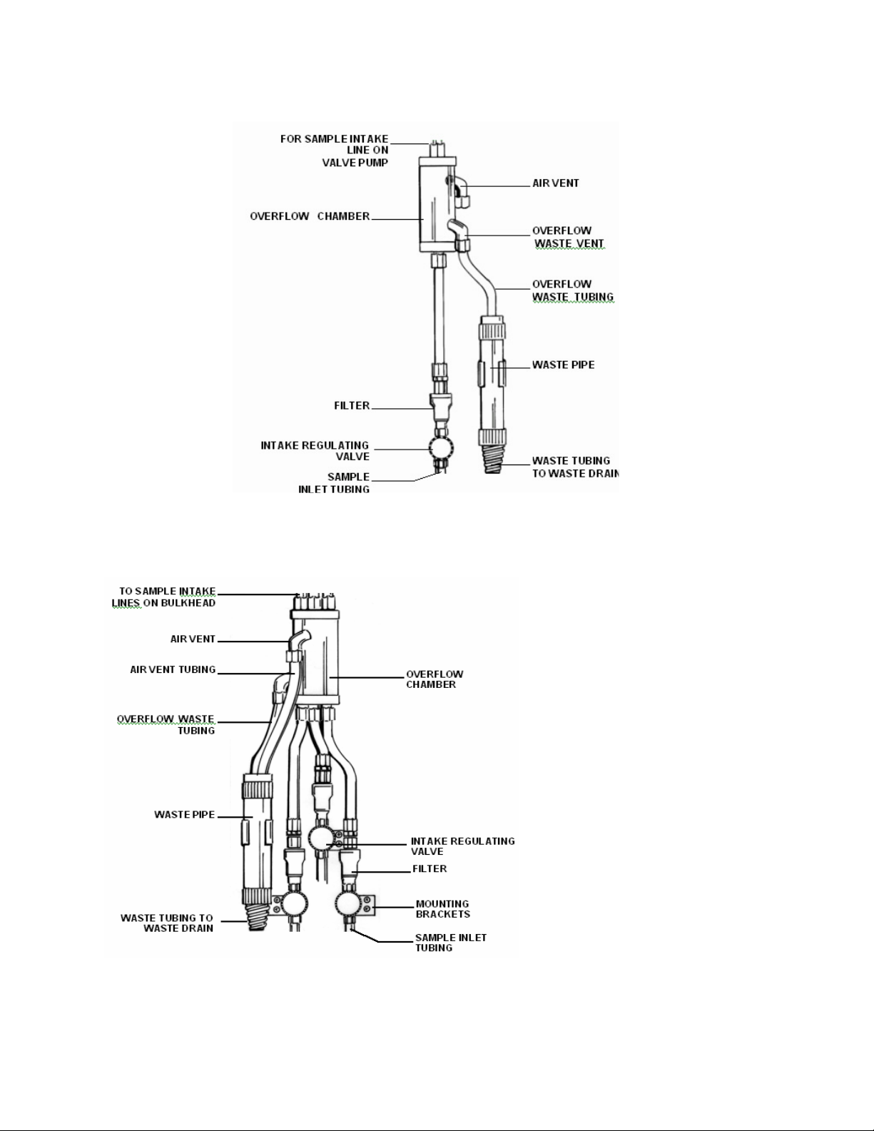
2.5 Mount Overflow Sampling Assembly
The Sample intake tube should extend into
The overflow tube approximately ½” – 1”
To mount overflow sampling assembly proceed as follows (for sample configurations, see
Figures 2-4a and 2-4b):
1. Mount overflow sampler assembly on outer, right side of reagent cabinet using the
provided four machine screws. For multi-stream units, mount overflow assembly on
left side of cabinet. (If using IF-100 In-Line Filter, refer to instruction sheet
accompanying filter for complete installation instructions.)
2. Place ends of air vent tubing and overflow waste tubing into waste pipe.
3. Connect waste pipe to drain.
4. Supply sample stream to regulating or intake valve with 1/4? tubing (plastic or
steel) as follows: Insert tubing into tube fitting. Make sure tubing rests firmly on
shoulder of fitting and nut is finger-tight. Mark nut at 6 o’clock position. While
holding fitting body steady with a wrench, tighten nut 1-1/4 turns (go to 9 o’clock
position).
5. For multi-stream assembly, connect sample intake line to bulkhead fitting.
6. For single-stream assembly, attach sample intake line to valve pump.
7. Make sure that sample liquid overflows into overflow chamber.
(1.25 – 2.54 cm).
13
Page 15
CFA-3000 Colorimetric Analyzer
Instruction Manual
Figure 2-4a. Single-stream Overflow Sampling Assembly
Figure 2-4b. Multi-stream
Overflow Sampling
Assembly
three-stream option)
14
Page 16

CFA-3000 Colorimetric Analyzer
Instruction Manual
2.6 Prepare Electrical Connections
WARNING:
Connect output signals, if any, before connecting the power supply.
CAUTION:
For proper operation and for safety, electrical connections to this equipment
must be made in accordance with local or national electrical code as applicable.
This equipment must be grounded. A qualified electrician should wire this
equipment to an electrical circuit.
Electrical connections are made to and from the cabinet at the input/output panel, located on
the left side of the analyzer. See Figure 2-5.
Terminals are provided for ground, power supply, high/low alarms, output signals,
calibration and status relays
.Output signals - a voltage output of 0-5 Vdc and a floating, ungrounded current
output of 4-20 mA are available for remote readout or control of a process.
Also available are contact closures for the following:
High alarm Leak Alarm
Low Alarm Lamp Alarm
Calibration
To make electrical connections, proceed as follows:
Use cable glands to hold cables securely in holes above input/output panel.
1. Remove solid caps from the holes above the input/output panel by puncturing with an
awl and prying them out. (Note: remove caps only from those holes that will be used.)
2. Replace with permanent connectors.
3. Connect alarms and external computer interfaces (if any).
4. Feed 3-wire power cable into analyzer through hole above the input/output panel.
5. Connect wires to appropriate contacts on Terminal Strip TB3.(See next page)
15
Page 17
CFA-3000 Colorimetric Analyzer
Instruction Manual
Figure 2-5. Input/Output Panel
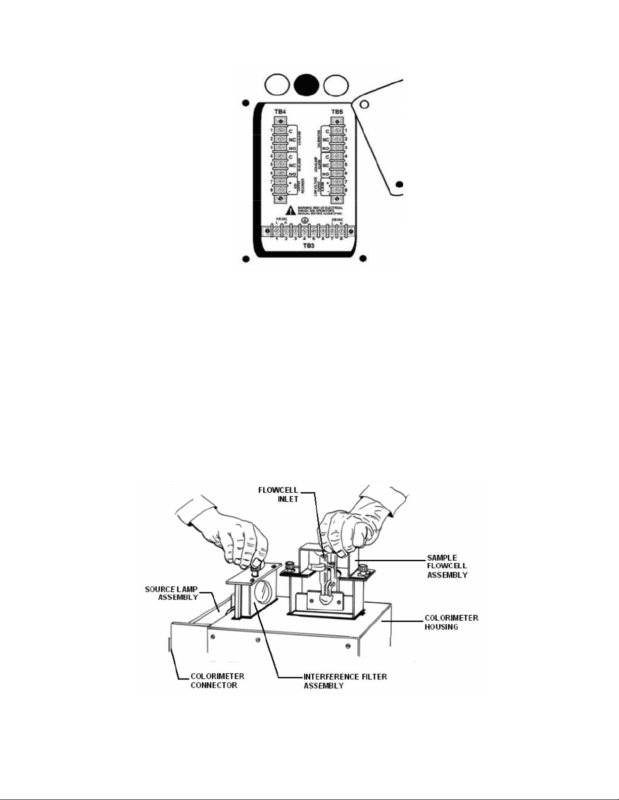
2.7 Colorimeter Assembly Installation
(assembly comes factory-installed)
To install colorimeter assembly, proceed as follows:
1. Insert flowcell assembly into slot on top of colorimeter (interference filter and lamp
pre-installed as part of the colorimeter assembly (see Figure 2-6).
2. Hand-tighten thumbscrews on top of flowcell assembly. Then, tighten screws onehalf turn with screwdriver.
3. Slide colorimeter into connector in inside back of cabinet (refer to Figure 2-1).
Housing will latch in place, automatically.
Figure 2-6. Colorimeter Assembly
Pls Note: lamp may be halogen or LED; filter or aperture may be used
16
Page 18

CFA-3000 Colorimetric Analyzer
Instruction Manual
2.8 Install Valve Pump Assembly
The pump assembly has a vacuum pressure system that:
o Eliminates internal pump tubing
o Uses significantly less reagent
o Accurately moves fluids through the analyzer.
Perform the following procedure to install valve pump assembly:
1. Tilt pump assembly towards you.
2. .Align the hinge pins and sockets, and slide assembly tray as far as possible to
right (see Figure 2-7). Carefully lay tray down into cabinet
3. Plug in the two connectors to the back of the cabinet (6-position connector for
heating bath; 9-position connector for pump) (see Figure 2-8).
4. Connect 16-pin connector from pump assembly to small connector on CPU board
(yellow ejector) above connector for keypad panel.
5. Attach colorimeter inlet tubing on left side of pump to flowcell inlet (see Figure 2-
1).
6. Continue with procedure depending on whether system is single-stream or multistream
For single-stream, continue:
6. Thread tube labeled Sample" through hole 0n bottom of shelf to the right of pump
assembly, and out through hole on left side of cabinet.
7. Connect Sample tube to top of overflow sample on left side of cabinet.
8. Guide all other tubes that are attached to valve pump assembly through reagent
cabinet access hole.
For multi-stream, continue:
6. Thread Sample tube from pump assembly through reagent access hole on the
right side of the valve pump assembly, and connect to Common (C) on #1 multistream solenoid valve on left side of reagent cabinet.
Guide all other tubes that are attached to valve pump assembly through reagent cabinet
access hole.
17
Page 19

CFA-3000 Colorimetric Analyzer
Instruction Manual
Figure 2-7. Valve Pump Assembly (comes factory-installed)
Figure 2-8. Pump Connector
(Pls Note: Heating Bath is not usually used on colorimetric Valve-Pump systems,
but may be required for ammonia systems.
18
Page 20

CFA-3000 Colorimetric Analyzer
Instruction Manual
2.9 Prepare Reagent Containers
Prepare reagent containers as follows:
1. Remove screw caps from reagent bottles.
2. Using an awl, make one hole in foil for the reagent straw. DO NOT let awl touch
reagent.
3. Place Standard and Reagent bottles into reagent cabinet, as shown in Figure 2-9.
4. Insert color-coded reagent straws and labeled Standard straw leading from valve
pump assembly into holes punched in corresponding bottles.
Figure 2-9. Five Liter Sample Bottle Placement in Cabinet (for all methods; colors
refer to reagent straw colors)
19
Page 21

CFA-3000 Colorimetric Analyzer
3.0
Operating the Analyzer
Instruction Manual
2.0 Analyzer
2.0 Analyzer
3.1 Operational Overview
The analyzer uses a batch flow method for automatically analyzing a sample against a fixed
standard (refer to block diagram in Figure 3-1). That is, the touch of a button starts the
microprocessor-controlled program, calibrates the analyzer, takes measurements of
samples, and reports results directly --- unattended---for months at a time.
The automated monitoring program determines the sequence for activating each of the valve
pumps in the valve pump assembly to inject air and fluids into the reaction chamber. Each
valve pump is associated with a specific input via the quick disconnect connector on the side
of the assembly (the number of reagents is determined by your particular chemistry and
procedure).For example, the inputs for silica chemistry would be:
Sulfuric acid, reagent #1
Ammonium molybdate, reagent #2
Oxalic acid, reagent #3
Reducing reagent #4
Sample
Grab sample
Baseline
Standard
Air
Flow cell wash
Evacuation of chamber
Re-circulate
For a multi-stream system, solenoid valves in the analyzer reagent cabinet open and close
streams for sampling. When sampling, the keypad panel LEDs identify which sample stream
(valve number) is associated with the displayed value, and which valve is now open for
sampling. Although the system runs samples on its own, you may also perform a manual
grab sampling or a manual calibration at any time.
20
Figure 3-1. Simple Block Diagram
Page 22

CFA-3000 Colorimetric Analyzer
Instruction Manual
3.2 Check Sample Stream
Check that the sample intake tube is ½ to 1 inch (1.25 to 2.54 cm) into the liquid.
Sample should just overflow the overflow tube. There should be no particulate or
bubbles in the tube.
Using a Multi-Stream Overflow Sampler
Multi-stream analysis requires an overflow sampler assembly that will accommodate the
extra sample streams. One multi-stream chamber allows for up to three sample streams; for
4 - 6 streams, use two chambers.
The sample tubes connect to solenoid valves in the reagent cabinet. The analyzer uses the
valves to cycle through all sample lines, in sequence. First, stream 1 valve is opened, and
Valve 1 LED on the keypad panel is lit. When the measurement is complete, Valve 1 will be
closed, and Valve 2 is opened to begin sampling stream 2. The keypad panel will show
Valve 1 LED lit as the Displayed Stream, and Valve 2 LED is lit for the Selected Stream.
LEDs on the valve pump assembly light up when a particular fluid is taken up by the valve
pump assembly. Figure 3?2 identifies the valve pump LED designations.
3.2.1 Check Fluidics
Check the following:
Colorimeter inlet tubing is in place and secure in sample flowcell inlet.
Liquid should overflow in overflow chamber.
Waste tubing is in waste pipe.
Sample tube is connected to Overflow Sampler Assembly for single stream; and, for
multi-stream, it is connected to Common (C) port of sample solenoid valve #1, on left
side of reagent cabinet.
System has no leaks.
3.2.2 Check Reagents
Check the following:
One hole has been punched in all reagent cap liners.
Reagent straws are placed in appropriate reagent containers.
High and low standard tubing are in appropriate containers.
3.2.3 Turn On Power
1. Open the keypad panel door to expose the circuit boards.
2. Press each board in to ensure proper seating.
3. Simultaneously press Power button on the back wall of upper cabinet and Reset
button on the CPU board (yellow ejector), then release.
21
Page 23

CFA-3000 Colorimetric Analyzer
Instruction Manual
4. First release the Power button, then the Reset button. The Keypad should display
”H E L O", then four dashes "-- -- -- --".
5. Pull pump forward and check leak detector by dipping finger in tap water and
touching detector behind pump. Leak detector LED on keypad panel will light up.
6. Turn main power switch to OFF
7. Dry leak detector.
8. Wait 20 seconds, then switch main power switch back to ON. Leak detector LED
should be off.
3.2.4 Test Valve Pump Operation
Reaction cell takes approx. 30 minutes to heat up.
If leak detector LED does not light up:
Adjust potentiometer on analog board counter-clockwise for more sensitivity.
Turn off power to reset system.
Wait 20 seconds, and simultaneously press Power and Reset buttons.
Dip finger in tap water and touch leak detector contacts on bottom of cabinet behind
the valve pump. LED should light up.
If problem persists, contact Rosemount Analytical.
The test procedure allows you to confirm that all physical connections are installed properly,
and to ensure that the pump is taking up the proper fluids at the correct time.
Enter Test Mode:
1. Put all straws and Sampling tube into a beaker of DI water.
2. Turn power on by simultaneously pressing Power button on the back of upper
cabinet and Reset button on CPU board (yellow ejector).
3. First release Power button, then Reset button. Keypad should display "H E L O",
then four dashes "-- -- -- --".
To enter test mode, continue with the step appropriate for your analyzer setup:
For single-stream,
continue:
For multistream,
continue:
Referring to Figure
3-2, on keypad
panel, press
position 15 and
then 2.
On keypad panel,
press:
then
.
22
Page 24

CFA-3000 Colorimetric Analyzer
Instruction Manual
The keypad buttons may now be used to test pump operation. Do not rush through the
test steps – when a specific step is initiated, it takes approx. 2 seconds to pump air
through the system. Actual pumping of a liquid takes approximately 4 seconds. After this
operation is finished, another 4 seconds elapses before the pump is primed for the next
test step.
To exit the test at any time, press the ENTER button on the keypad panel.
If a test step does not work properly, try the following:
Take a syringe and shoot air through straw to make sure it is not clogged.
Check that corresponding LED on valve pumps lights up (refer to Figure 4-1).
Check that fluid is picked up in correct tube.
If the problem still persists, contact Rosemount Analytical.
Single-Stream
Keypad
Multi-stream
Option
Figure 3-2. Numbered Positions
Begin Test:
Confirm that the corresponding Pump LED lights up for each step (refer to Figure 3-3 for
LED designations during test):
23
Page 25

CFA-3000 Colorimetric Analyzer
Instruction Manual
1. Press ZERO to test air. Press ZERO to turn off.
AUTO
2. Press to simulate one shot of Reagent #4. Look at blue straw to confirm that
MULTI
water is pumped up through tube. Repeat a few times until you see water is in clear
section of tube.
3. Press to simulate one shot of Reagent #3. Check green straw and its clear
MANUAL
tube.
4. Press to simulate one shot of Reagent #2. Check orange straw and its clear
SET
STREAM
tube.
5. Press to simulate one shot of Reagent #1. Check red straw and its clear tube.
HIGH
6. Press to simulate one shot of Sample coming from overflow sampler. Check
ALARM
tube labeled "Sample."
SCALE
7. Press to simulate one shot of Standard. Check corresponding clear straw and
20mA
its clear tube.
REAGENT
8. Press to simulate one shot of Standard solution. Check clear straw labeled
LEVEL
STANDARD and tube.
9. Repeat Step 9 until you see fluid shoot into reaction chamber.
LOW
10. Press to simulate evacuation from the reaction chamber to the flowcell.
ALARM
Check the tube going up to flowcell.
GAIN/
11. Press to simulate one shot of Grab solution. Check clear straw and tube.
mV
12. Press to wash flowcell.
LOW
13. Press to empty reaction chamber. If there is any fluid left, it will be shot
ALARM
through to Waste.
LOW
14. Press once to exit test.
ALARM
24
Page 26

CFA-3000 Colorimetric Analyzer
RECIRCULATE
STANDARD
BASELINE
EVACUATE
AIR
GRAB
REAGENT 4
REAGENT 2
SAMPLE
REAGENT 3
REAGENT 1
FLOWCELL WASH
STANDARD
OPERATIONS
TEST
OPERATIONS
REAGENT
LEVEL
4mA
LOW
ALARM
SCALE
20mA
ZERO
BUTTON
GAIN
mV
HIGH
ALARM
MANUAL
SET
STREAM
AUTO
MULTI
Instruction Manual
15. Restore all tubes to appropriate reagent containers.
16. Connect tube leading to Overflow Sampler for single-stream system, or to Sampling
solenoid valve #1 for multi-stream system.
NOTE: The LCD on the display board will display the keypad position which is
assigned to a specific valve-pump. When the LCD number disappears, the
next position may be pressed. The sequence is given on page 24.
Figure 3-3. Valve Pump LED Designations
25
Page 27

CFA-3000 Colorimetric Analyzer
Instruction Manual
3.2.5 Set Up Stream Parameters
The analyzer is programmed to measure a single-stream system at 4 sample cycles per
hour. The multi-stream default is 1 cycle per stream, but you may define parameters for
individual streams, such as modifying the number of cycles or the alarm threshold values.
The alarm values are used to activate alarms or controllers when the sample is outside of
the specified concentration range. A high alarm will activate when the sample concentration
exceeds a pre-set limit. A low alarm will activate when the sample concentration is below the
pre-set limit.
The contacts for the alarm outputs are located at the input/output panel on the cabinet side.
The system must be in an alarm condition for at least one minute to activate the alarm
contact.
Use the logical flows below to define desired stream parameters.
Figure 3-4. Logic Flow for Single-stream Parameter Definition
26
Page 28

CFA-3000 Colorimetric Analyzer
Instruction Manual
Default Display:
1 0 0 1
(Stream 1, one
cycle)
Change
Change
Stream
Stream
Number?
Number?
NONO
Change
Change
Number of
Number of
Cycles?
Cycles?
YESYES
NONO
Sample Display:
2 0 0 1
(Stream 2, one cycle)
Set
Set
Alarms?
Alarms?
NONO
Go to Next
Go to Next
Stream
Stream
YESYES
Sample Display:
1 0 0 2
(Stream 1, two cycles)
YESYES
Set High
Set High
Alarm?
Alarm?
YESYES
NONO
Default Alarm
Display:
0 0 0 0
Alarm LED
lights up, if
alarm is on
Sample Display
for 10 ppb:
0 0 1 0
NOTE: if setting High Alarm, Low Alarm
must be set lower than High
Alarm Value
Set Low
Set Low
Alarm?
Alarm?
YESYES
NONO
Figure 3-5. Logic Flow for Multi-stream Parameter Definition
27
Page 29

CFA-3000 Colorimetric Analyzer
Instruction Manual
3.3 Set Reagent Supply Time
Use the keypad panel to remind you when you need to replace the reagent. The analyzer
will count pump cycles and count down the number of days left. To specify the duration,
proceed as follows:
1. Press
Sample Display: 0 0 9 0
2. Press
To determine how many days are left until you have to replace reagent,
press once.
Look at the LCD and record the number of days;
then press
once to set counter for 90 days (3 months).
to exit and clear display.
again to get out of mode.
3.4 Set Scaling Outputs
Set output 4 -20 mA 0 -5 Vdc from the keypad panel, (refer to Figures 7 -2 and 7 -3), then
adjust 4-20 mA and 0-5 Vdc at your external device.
Set output scale to: 4 mA/0 V
1. Press .once then .to display 4 mA and for 0 Vdc.
The sample Display for 4 mA and for 0 Vdc: 0 0 0 4
2. To exit, press
Set output scale to: 20 mA/5 V
1. Press
28
once then to display 20 mA and 5 Vdc.
Page 30

CFA-3000 Colorimetric Analyzer
Instruction Manual
The sample Display for 20 mA and for 5 Vdc: 0 0 2 0
2. To exit, press
ENTER
To display the Full-scale concentration value embedded in the E-Prom:
SCALE
Press two times. To exit, press
20mA
ENTER
3.1.5 Record GAIN and mV
Record GAIN
Use the GAIN value to help identify the energy level of the Colorimeter. A Gain decrease
may indicate that there is a problem with the electronics, the optics, the flowcell, or the
source lamp. An average Gain value should range from 9 -11. Higher than this range
shows low energy; lower than this range shows too much energy.
GAIN
1. Press twice. Sample Display for value of 11: 0 0 1 1
2. To exit, press
D mV
ENTER
Record
DmV
Use the DmV value to determine that the method’s span and slope are correct. The
change in millivolts (
DmV) is the spread between a baseline and a full-scale standard at
the time of calibration. The values are relative to the chemical parameter being measured
Record the millivolt values for both baseline and full-scale standard.
GAIN
1. Press
D mV
The sample Display for value of 150 mV is: 0 1 5 0
2. To exit function, press
ENTER
29
Page 31

CFA-3000 Colorimetric Analyzer
Instruction Manual
3.4.2 Initiate Auto Calibration
Some silica analyzers are shipped with the auto calibration feature disabled. These
instruments are typically used in high ambient temperature applications. For these
instruments, calibration will be initiated by pressing the AUTO CAL. button followed by
pressing the ENTER button once a week. This shall be done once each seven days
following the first calibration (startup calibration).
Before starting calibration, make sure that the analyzer is running reagents
and baseline solution for at least 20 minutes. **
AUTO
To initiate auto calibration, press on the keypad panel – the CALIBRATION LED
will light. When multi-stream systems are being calibrated, only Stream 1 LED is lit.
CAL.
Baseline calibration will run first for approximately 17 minutes. Full-scale calibration
follows, lasting approximately 17 minutes (the actual time for calibration depends on the
chemistry). When full-scale calibration is finished, CALIBRATION LED goes out and the
value is displayed on the LCD. The “-000-” display signifies that a delay is required before
the next sample is displayed.
Sample analysis automatically begins after calibration. The time delay from the start of
sample analysis to display of results is approximately 17 minutes. This allows sufficient
time for the previous solution to wash through system, for sample and reagents to react,
for analyzer to measure sample and display concentration value.
When the CALIBRATION LED and the ”-000-” display in a single -stream system go out,
the displayed value on the keypad panel is the actual stream value.
For a multi-stream system, after auto calibration, Sample Stream status LEDs will light to
show sample stream valve currently selected and sample stream concentration currently
displayed. For example, for the first stream sample, VALVE SELECTED LED is lit for that
stream; dashes display on the keypad panel. When analyzer finishes sampling one stream
and moves on to the next, the display shows the previous sample stream concentration
value, and its VALVE DISPLAYED LED lights up. VALVE SELECTED LED will be lit for
next valve in sequence.
Note: If for any reason a calibration is not wanted and needs to be aborted, press:
DECIMAL
HIGH
then , then to abort the calibration. Press twice in rapid
ALARM
SET
STREAM
succession on initial start-up for priming of sample & reagents.
30
AUTO
CAL.
Page 32

CFA-3000 Colorimetric Analyzer
Instruction Manual
3.5 Process a Grab Sample
The analyzer allows you to rapidly analyze a grab sample.
Press
holder on the overflow sample panel.
The procedure below can be performed at any time, even in the midst of sampling.
If visible, suspended solids are present in the sample, filter it to 8 microns or less.
1. Place the clear grab sample inlet tube into a beaker containing the grab sample.
2. Press
The system analyzes the grab sample and after 15 minutes, displays the results
when complete (The results are “flashed” on the display).
After the display of the grab sample’s value, a multi-stream analyzer begins
processing the next stream in sequence.
on the keypad panel, to introduce a grab sample into the analyzer from the
one time. The display shows flashing dashes, “ -- -- -- --“ .
Grab Sample Display: 0 0 2 0 (flashing for three minutes)
3. To display measurement for previous grab sample, press
4. Press button to return to normal operation.
twice.
3.6 Manually Sample a Particular Stream.
Use this procedure to manually switch between sample streams in a multi-stream system.
This operation can be performed at any time, except during calibration.
Press one time. Sample Display: 0 0 0 1 .
Press and to change stream number. Sample Display: 0 0 0 3
Press to start sampling desired stream.
31
Page 33

CFA-3000 Colorimetric Analyzer
Instruction Manual
Press to return to multi-stream automatic analysis.
3.7 Shutdown
To shut down the CFA-3000 for only a few days, press main Power button in back of upper
cabinet to OFF position. Leave reagent straws in reagent containers.
To shut down the analyzer for more than a day, perform the following procedure:
Some chemistries may require specific wash solutions. Check Appendix A,
"Chemistries," for details.
1. Remove straws from reagent containers and place them into a beaker of DI water.
2. Press
twice within a two-second interval to activate priming. This allows wash
solution or DI water to be injected rapidly through system.
3. After priming finishes (after 10-15 minutes), press the main Power button in back of
upper cabinet to OFF position.
3.8 Quick Start
If the analyzer has been shut down during normal operations, turn power on and press
once.
If the CFA-3000 has been turned off for an extended shutdown:
1. Press
2. Press once to perform calibration.
twice to prime.
32
Page 34

CFA-3000 Colorimetric Analyzer
4.0
Maintaining the Analyzer
Instruction Manual
Your CFA -3000 Series analyzer is a precision instrument which, if maintained prop erly,
should provide years of accurate and reliable service.
4.1 Analyzer Equipment.
Even though the analyzer normally runs automatically, perform the following activities,
quarterly:
1. Start Auto Calibration after reagent replenishment (see Section, "Perform Auto
Calibration").
2. Check mV value.
3. Check Gain value.
4.2 Colorimeter Assembly
Remove assembly from cabinet, inspect annually (refer to Figure 4-1):
Flowcell drip tray
Optics lens
Interference filter assembly or aperture
LED or Halogen lamp
Note: To replace Colorimeter parts, refer to Section 6, REPAIR PROCEDURES?.
Use the following procedure to inspect and clean the Colorimeter assembly:
1. Remove colorimeter housing from inside back of cabinet.
2. Loosen thumbscrews on top of flowcell assembly, and carefully lift it out of housing
(see Figure 4-1).
3. Clean the interference filter (if present) with optical cleaning paper or cloth. (Use only
material designed to clean optical surfaces).
4. Return interference filter assembly (if present) into the colorimeter housing and
secure with the thumbscrew (2 hand turns, then ¼ to ½ turn with screwdriver)
5. Loosen thumbscrews on top of the flowcell assembly and carefully lift it out of the
housing (see figure 4-1)
6. Clean the flowcell using following procedure:
a. Remove four screws attaching flowcell shell cover.
b. Remove shell and mounting cover.
c. Drain excess fluid in flowcell drip tray.
d. If a colored “coating” is visible in the flowcell, pour in 0.5 normal NaOH solution
(part no.180-1030-42) into the top vent of the chamber until fill level remains
stable in the chamber.
33
Page 35

CFA-3000 Colorimetric Analyzer
Instruction Manual
e. With a cotton swab or pipe cleaner, remove residual waste from inner walls of
the flowcell.
f. Flush with DI water when finished and replace shell cover.
7. Return flowcell assembly into colorimeter housing and secure with thumbscrews,
then tighten with a screwdriver.
8. Inspect source lamp (if halogen bulb; it should last at least 1 year; if LED it should
last for 10 years or more.)
Figure 4-1. Colorimeter Assembly
Note: Source lamp may be a halogen bulb or a wavelength-specific LED, depending upon
the method’s requirements. Also, an interference filter or an aperture may be used to
control the amount of energy required for optimum measurement.
34
Page 36

CFA-3000 Colorimetric Analyzer
5.0
Troubleshooting Procedures
Instruction Manual
This chapter is divided into two sections:
Troubleshooting Chart: -a list of symptoms, probable causes, and remedies.
Test Functions:– test functions for diagnostic information.
Troubleshooting Chart
Symptoms observed during operation are generally enough to identify a faulty
component.Such symptoms, together with probable causes and remedies are listed in the
following troubleshooting chart.
Table 5.1: Troubleshooting Chart
Problem
No power
Pump is
inoperative
Keypad
lights or
display
fails to
light up
or buttons
fail to
operate
Keypad
lights or
display
fails to
Probable
Cause
Power
switch OFF
Power
switch
defective
Valve pump
switch OFF
Blown fuse Replace fuse
Leak
detector
activated
Bad
electrical
connection
Still
inoperative
Circuit
boards are
not seated
properly
Display or
associated
power circuit
faulty
Circuit
boards are
not seated
properly
Press power
switch ON
Call
Rosemount
Analytical
Press switch
ON
Find and fix
leaking;
check
pump’s
electrical
connection
Check
pump’s plugs
to CPU &
connector
Call
Rosemount
Analytical
Remove and
reinstall
circuit boards
Call
Rosemount
Analytical
Remove and
reinstall
circuit boards
Remedy
Problem
light up
or buttons
fails to
operate
DO NOT ATTEMPT TO REMOVE OR
INSTALL PC BOARDS UNLESS SYSTEM
Problem
Alarms
not
activated
Probable
Cause
Display or
associated
power circuit
faulty
Connector
faulty or not
properly
inserted
Remedy
Call
Rosemount
Check
connection,
including
plastic
connector
from keypad
to display
board
WARNING:
POWER IS TURNED OFF!
Probable
Cause
Incorrect
settings
Readjust
settings, making
sure that low
alarm is set
lower than high
alarm setting.
Remedy
35
Page 37

CFA-3000 Colorimetric Analyzer
Instruction Manual
Problem
Signal
not
repetitive
(same
sample
not
repetitive)
No
signal, or
signal offscale
high
No
signal, or
signal offscale
high
Problem
Loss of
sensitivity
Reagent
Loss of Replace
Probable
Cause
Insufficient
time for alarm
to respond
Small leak or
clogging in
fluidics
Lamp leads
loose at
terminal board
Optical
component
loose
Precipitate in
flowcell
Clogged
tubing
Connector or
wires loose
Lamp power
supply faulty
Connector or
wires loose
Lamp power
supply faulty
Faulty circuit
board
Incorrect mV
value or LED/
lamp is not on
Probable
Cause
Reagents old,
contaminated
or improperly
prepared
straws in
wrong
container
Remedy
Alarm condition
must exist for
minimum of 60
seconds before
alarm activates.
Check all tubing
lines and
connections
Tighten lamp
leads
Tighten
aperature
holder and
flowcell
Flush out
flowcell
Replace
Check circuit
boards for
proper seating
Replace lamp
power supply
Check circuit
boards for proper
seating
Replace lamp
power supply
Replace power
supply circuit
board;
Check mV value -
- if not correct,
call Rosemount
Analytical
Remedy
Change
reagents
Check
placement of
straws
Problem
Decreased
pumping
volume
Leak
detector
LED lights
up
Lamp LED
lit
Problem
Silica
analyzer
flowcell is
colored
Excessive
Colorimeter
source
Probable
Cause
Remedy
sample flow sample filter at
overflow panel
Tubes
pinched shut
or clogged
from deposits
Remove
condition
causing
“pinched”
lines; replace
sample filter at
overflow panel
Leak in
fluidics
Repair leak
and dry leak
detector
contacts;
turn main
power OFF for
20 seconds
High humidity Adjust screw
on leak
detector
potentiometer
on analog
board; turn
clockwise to
decrease
sensitivity
Connector
faulty or not
properly
inserted
Check
connection to
analog board;
replace analog
board
LED or Bulb
out
Lamp power
supply is
faulty
Check bulb or
LED
Check for
proper output
voltage – 5.0 ±
0.1 Vdc
Probable
Cause
Reagent
deposits
Rinse fluidics
with 0.5N
Remedy
NaOH, see
Maintenance
section
Refer to
silica
concentrations
Lamp or LED
burned out
Appendix,
"Chemistries"
Replace lamp
or LED
36
Page 38

CFA-3000 Colorimetric Analyzer
Instruction Manual
Problem
lamp or
LEDdoes
not light
Power supply
Faulty
Probable
Cause
failure
connector
Remedy
Call Rosemount
Analytical
Call Rosemount
Analytical
5.2 Test Functions
The analyzer has a number of test
functions available for diagnosing
problems
Table 5.2. Test Functions
Check Test Procedure Exit
Front
panel
display
System
sensitivit
y
( mV )
Test LEDs and LCD on
keypad:
a. Press Power button
and Reset button on
the CPU board (yellow
ejector).
b. Release power, then
Reset button.
c. Press the following
keys in sequence:(key
#’s 15, 5, 6)
Press:
then
Press:
Press:
then
Check Test Procedure Exit
Check
lamp
power
supply in
rear of
cabinet
Check
Gain
value:
if flowcell
and
optics
are in
good
working
condition,
gain
should
not vary
from
initial
value (±
2 units)
Locate test points on
lamp power supply
with a meter. Power
supply for 5 Vdc lamp
should measure 5.0
V dc.
Press
twice.
Press
twice
37
Page 39

CFA-3000 Colorimetric Analyzer
Instruction Manual
6.0 Repair Procedures
The Colorimetric analyzers are designed with modular components for quick and easy
replacement. The following sections contain instructions to remove parts and replace them.
For more complex repairs, or diagnostic assistance, contact Rosemount Analytical at:
Telephone: (800) 854-8257, (949) 757-8500
Fax: (949) 863-9159
6.1 Replace Valve Pump Assembly
Use the following procedure to replace pump assembly:
1. Turn off power to analyzer.
2. Pull back of pump assembly towards you to a 45-degree angle (see Figure 6-1).
3. Unplug the two connectors from the back of the cabinet. (9-position connector for
pump).
4. Disconnect pump assembly’s “D” connector from right side of pump.
5. Remove all liquid tubes from pump.
6. Disconnect flowcell inlet tube** from bottom of reaction cell (right side of valve pump).
7. Slide assembly to the left to disengage from pins, and remove pump assembly.
8. To install a new pump assembly, refer to Section, " Install Valve Pump Assembly".
** Note: Be extremely careful-flowcell is very fragile
Figure 6-1. Remove Valve Pump Assembly
38
Page 40

CFA-3000 Colorimetric Analyzer
Instruction Manual
6.2 Replace Circuit Boards
Use the following procedure to replace circuit boards:
1. Turn off power.
2. Open latch from right side of keypad panel; and open door.
3. Disconnect all cables and plugs from board to be replaced.
4. Unlatch colored clip from board to be replaced (refer to Figure 6-2).
5. Pull circuit board straight out.
6. Reverse steps to replace board and reconnect cables. Press firmly to ensure that
boards are properly seated.
7. Turn power on.
8. Perform Automatic Calibration (refer to Section, “Initiate Auto Calibration”).
Please NOTE: Valve-pump connector is on CPU board
WARNING: DO NOT ATTEMPT TO REMOVE OR INSTALL PC BOARDS
UNLESS SYSTEM POWER IS TURNED OFF!
Figure 6-2. Card Cage
IMPORTANT: Do Not remove any PC board or component without first shutting off
Power to the analyzer.
39
Page 41

CFA-3000 Colorimetric Analyzer
Instruction Manual
6.3 Replace Fuses
Use the following procedure to replace fuses (all fuses are 1A):
1. Turn off power.
2. From inside upper left corner near pump switch, press down on fuse cap and turn
counter-clockwise to remove.
3. Pull fuse and cap straight out.
4. Replace fuse in cap (make sure the new fuse is the same type and rating as the one
you are replacing).
5. Press fuse cap in place and turn clockwise.
6. Turn power on.
6.4 Replace Colorimeter
Components
When replacing Colorimeter components
always take care not to damage flowcell.
To replace colorimeter assembly or any of
its components, first do the following (refer
to Figure 6-3):
Turn off power.
Loosen spring-loaded latch on right side of
colorimeter housing the cradle. Slide the
colorimeter out of connector. Place on a
clean, stable surface.
4. Install the new flowcell assembly into
colorimeter housing and secure with
thumbscrews (two hand turns then one
turn with a screwdriver
6.4.1 Replace Interference Filter
Or Aperture
1. Loosen thumbscrew on top of
interference filter or aperture
assembly.
2. lift the assembly out of housing.
Install a new assembly into the
colorimeter housing and secure
with thumbscrew (two hand turns,
then one turn with screwdriver).
6.4.2 Replace Flowcell
1. Loosen two screws on top of the
flowcell assembly
2. Lift the flowcell assembly out of the
housing
3. Discard the contents of the flowcell.
Figure 6.3: Colorimeter Components
4. Install the new flowcell assembly into
colorimeter housing and secure with
thumbscrews (two hand turns then one turn
with a screwdriver..
40
Page 42

CFA-3000 Colorimetric Analyzer
Instruction Manual
6.4.3 Replace 5 Vdc Or LED Source Lamp
Use the following procedure to replace a 5 Vdc lamp (halogen “long-life” bulb or LED):
1. Turn off power to analyzer.
2. Remove the colorimeter housing from inside back of cabinet, and let the lamp cool
down.
3. Loosen contacts in lamp housing and remove lamp lead wires
4. Unscrew two screws securing lamp block to housing, and remove block.
5. Take out lamp by loosening middle screw.
6. Re-install new bulb and block.
7. Re-connect lamp lead wires to screw contacts next to lamp.
8. Power up analyzer.
NOTE: The LED is polarity-sensitive; be sure to connect the “+” (positive) lead to the “+”
terminal of the 2-position block.
Figure 6-4. Replace 5 Vdc Source Lamp
NOTE: The colorimeter may have either a halogen bulb or LED as a light source and; also
may have either interference filter or aperture.
41
Page 43

CFA-3000 Colorimetric Analyzer
7.0
I
nstrument Description
Instruction Manual
7.1 Analyzer Front View (Refer to Fig. 7-1).
7.1.1 Main Cabinet
Table 7-1. Main Cabinet Parts
Part Function
Main Cabinet
Reagent Cabinet
Door Hinges
Door Latch
Keypad Panel and
Driver Board
HB Lamp
HB T 1 A
LAMP PS T 1.0 A
PUMP T 1.0 A
XFMR T 1.0 A
Pump On/Off
On/Off
Colorimeter
Waste Drain Pan
Pump Connector
Heating Bath
Connector
Valve Pump
Assembly
Splash-proof enclosure
protects analyzer
Splash-proof enclosure
protects reagents and
solenoid valves
Pin hinges mount doors
on
main and reagent
cabinets
Secures cabinet door
External side contains
touch buttons for
controlling analyzer,
digital display, and status
panels. Internal side
contains driver board
Indicates when
proportional controller is
heating the heat bath
1 A fuse for heating bath
1 A fuse for power
supply to colorimetric
lamp
1 A fuse for pump
1 A fuse for transformer
Lighted switch controls
power to pump
Main power switch
Detector
Drain pan directs waste
solutions to waste tube
9-position connector
connects pump to main
cabinet electronics
6-position connector
connects to heating bath
assembly
Includes pump, PC
board, labeled tubes,
and reaction vessel
assembly (chemistry
module with integrated
heating bath)
Part Function
Chemistry
Module Tubing
Carries sample and
reagent to valve pump
assembly
Quickdisconnects
Connects reagents,
samples, and standards
to valve pump assembly
Waste Tube
Carries waste solutions
to drain
Leak Detector
Senses leakage of
solutions in main
cabinet, shuts pump off,
and activates leak LED
7.1.2 Reagent Cabinet
Table 7-2. Reagent Cabinet Parts
Part Function
Multi-Stream Valve
Panel
(Multi-Stream
option only)
Multi-Stream
Connector
(Multi-Stream
option only)
Bulkhead Fitting
Allows sequential
analysis of up to six
sample streams
Positive fit connector
connects Multi-stream
valve panel to main
cabinet electronics
Fitting that directs
individual sample
stream to sample
valve
Overflow Sample
Assembly
Supplies continuous
sample streams for
analyzer
42
Page 44

CFA-3000 Colorimetric Analyzer
Instruction Manual
For multistream monitor, Overflow Sampling Assembly
mounts on left side, when facing analyzer.
Figure 7-1. Analyzer Front View
43
Page 45

7.2 Keypad Panel
The keypad panel has a four-digit liquid
crystal display with an adjustable decimal
point. The panel also has indicator LED’s
and pressure-sensitive buttons.
Table 7-3. Buttons/LED Functions
Button/LED Function
For Both Single and Multi-stream Options
LEAK LED
CALIBRATION
LED
ISE/LAMP LED
REAGENTS LED
UP or DOWN
Arrow
When lit, indicates leak
in main cabinet
When lit, indicates
calibration in progress
Lamp bulb is out; (LED
will last for 10 years+)
but indicator will not
show LED out
When lit, indicates
reagents need to be
replaced
Increases or decreases
displayed value
Sets value or exits
function
Sets high alarm limit
Sets low alarm limit
Two functions:
-- Sets 90 day clock for
reagent usage
-- Displays number of
days remaining until
next replacement of
reagents
Sets scale to adjust
output to 4 mA and 0
Vdc on recording
device
Sets scale to adjust
output to 20 mA and 5
Vdc on recording device
Button/LED Function
Two functions:
-- Displays Gain value
For Multi-stream option only
Sample
Streams
LEDs
-- Displays change in mV
Initiates processing from
grab sample
Initiates automatic
calibration of analyzer
(Not used)
VALVE SELECTED
shows which valve
(stream) is being
analyzed, and VALVE
DISPLAYED shows which
valve is associated with
completed and displayed
value
Initiates automatic multistream analysis
Initiates single stream
analysis
Enters function to identify
parameters for each
stream (such as number
of cycles and high and low
alarms)
(Not used)
Page 46

CFA-3000 Colorimetric Analyzer
configurations:
Instruction Manual
7.3 Card Cage
The card cage is located directly behind
the keypad panel. To access the card
cage, lift latches from right side of keypad
panel and open hinged door. (Refer to
Figure 7-2.)
7.3.1 Card Cage and Door
Table 7-4. Card Cage Parts
Part Function
Keypad Panel
Door
Display Board
CPU Board
180-B028-01
Valve Board
180-B016-01
(only supplied for
multi-stream
option or for RS232 output on
single stream)
Analog Board
180-B025-02
For multistream
180-B025-01*
Power Supply
Board
180-B012-03
7.3.2 CPU Board
Table 7-5. CPU Board Components
Component Function
0Vdc - 5Vdc
Connector
4mA –20mA
Connector
Computer Memory
Opens to access card
cage
Circuit board contains
electronics for keypad
and
LCD display
Central processing
circuit
board processes the
signal
fed to the digital display
and any external
devices. (Yellow ejector)
Circuit board controls
multi-stream accessory.
Jumper should be
installed on back of
valve board. (Purple
ejector)
Circuit board converts
signals from analog to
digital and processes
signals from "fault"
detectors (Orange
ejector)
Supplies voltage to
electrical circuitry
(Blue ejector)
To recording device.
To recording device.
Clears microprocessor
Reset
Valve Pump
Connector
Display Board
Cable Connector
memory
Connector for cable
from valve pump
Connector for display
board cable
7.3.3 Analog Board
Table 7-6. Analog Board Components
Component Function
Potentiometer
Adjusts sensitivity of
leak detector –
clockwise for less
sensitivity; counterclockwise for greater
sensitivity
Analog Board
DIP Switch
Contains 8 rocker
switches for setting
various functional
processes (see Figure
7-3)
Signal Input
Connector
On 180-B025-01:
20 multi-stream
output
potentiometers
For process signals
For each stream 2 – 6,
potentiometers for 4 mA,
20 mA, 0 V, 5 V
(multi-stream only)
7.3.4 Valve Board
Table 7-7. Valve Board Components
Component Function
Multi-stream
Panel Connector
Connector for cable
connector from display
board
7.3.5 Power Supply Board
Table 7-8 Power Supply Board
Part Function
18-pin Female
Connector
6-pin Male
Connector
6-pin Female
Connector
For relays
Operating power
Valve Pump Power
45
Page 47

CFA-3000 Colorimetric Analyzer
Instruction Manual
Please NOTE: Valve-pump connector is on CPU board
Figure 7-2. Card Cage and Boards
IMPORTANT
: Do Not remove any PC board or component without first shutting off
Power to the analyzer.
46
Page 48

Page 49

CFA-3000 Colorimetric Analyzer
Instruction Manual
7.4 Colorimeter Assembly
The Colorimeter Assembly is housed on
the back wall of the upper cabinet slightly
above the valve pump assembly. Table 79 lists the components included in the
Colorimeter Assembly.
Table 7-10. Colorimeter Assembly Parts
Part Function
Colorimeter
Housing
Source Lamp
(halogen or LED)
Interference Filter
Assembly (or
Aperture)
Sample Flowcell
Assembly
Sample Flowcell
Inlet
Colorimeter
Connector
Contains and protects
optics and electronics
that measure
transmittance of reacted
sample stream
Provides light source for
colorimeter
Allows passage of
desired
wavelength/amount of
light from source lamp
beam
Reacted sample flows
through cell for analysis.
Sidearm of flowcell
which receives sample
Electronics connector
for colorimeter
Figure 7-4. Colorimeter Assembly
Please note:
o Either a halogen bulb or LED is the light source
o An interference filter or an aperture is used to control or reduce the amount of light as
necessary
48
Page 50

CFA-3000 Colorimetric Analyzer
Instruction Manual
7.5 Rear of Main Cabinet
In the rear of the main cabinet are a
number of electrical components and
connectors. The following diagram is for
reference, only.
Table 7-11: Back Cabinet Parts
Part Function
Backplane
Board
Power
Transformer
Heating Bath
Connector
Pump
Connector
220Vdc
Transformer
Circuit boards plug into
front side
Supplies ac voltage to
electronics
Interconnect to heating
bath
Interconnect to valve pump
Optional part for specific
electrical requirements
(208 V – 240 V)
Figure 7-5. Electrical Wiring and Components in Rear Cabinet
49
Page 51

CFA-3000 Colorimetric Analyzer
Instruction Manual
7.6 Valve Pump Assembly
The vacuum pump assembly includes the
pump, PC board, and reaction cell.
Table 7-12. Valve Pump Parts
Part Function
Pump Housing
Pump
Reagent Barb
Fittings
Reaction Vessel
Assembly
6-position
Connector
9-position
Connector
LED * Green is OK; RED is low
pressure
Contains and protects
valve pump electronics
Valve pump routes
sample and reagents
through the analyzer
Male half of tubing
connector. Tubes are
connected to reagents
and sample
Contains reaction cell,
heating block
Electrical power to
heating bath
Electrical power to pump
Part Function
Sample and
Reagent Tubing
“D” Connector Connects to small, 16-
Vent Line
Pump Drip Tray
LEDS
Color-coded straws and
labeled tubes for
transport of solutions
pin connector on CPU
board
Vents reaction cell to
waste
Catches leaks and
directs them to the leak
detector
Identify which injector is
active.
* Vacuum/Pressure LED is located on the
upper right corner of the Valve-Pump as it
is installed
Figure 7-6. Valve Pump Assembly
50
Page 52

7.7 Interface Ports
1 2 3 4 5 6 7 8 9 10 11 12 13 /
The interface ports (labeled for recorder,
printer, relay output, and RS-232) are
located on the lower, left outside wall.
Table 7-13. Interface Ports
Port Function
RS-232-C For connection of
computer interface or
other accessories
Relay Output Optional relay contact
(multi-stream analyzer
only)
Printer For connection of printer
cable
Recorder For connection of
external recorder; for
multi-output, 4-20 mA
and 0-5 Vdc outputs for
streams 2 through 6.
Table 7-14. Relay Output Option
Pin Assignments
Pin No. Description
1 NO 9 C Stream #1 Alarm or ID
2 NO 10 C Stream #2 Alarm or ID
3 NO 11 C Stream #3 Alarm or ID
4 NO 12 C Stream #4 Alarm or (#1*) ID
5 NO 13 C Stream #5 Alarm or (#2*) ID
6 NO 14 C Stream #6 Alarm or (#3*) ID
If there are 3 streams or less, both stream ID
and alarms may be optionally configured.
7.9 Multi-Output Board
The output for Stream #1 is obtained from the
Input/Output Panel (see Figure 2-5). The
additional five outputs are obtained from the
lower left-hand side of the analyzer. Table 714 gives the pin assignments on the “D”
connector for a multi-stream system:
____________________________________
\
\ 14 15 16 17 18 19 20 21 22 23 24 25_ /
Figure 7-7. Interface Ports
7.8 Relay Output Option
This port (see Figure 7-7) is a collection of
contact closures that can be used to
identify either the stream being displayed
or the alarm that is activated (multi-stream
systems only). these are not “powered”
contacts.
Relay Contact Ratings:
100 Vdc -- max voltage
10 Vdc-- max DC current
1.0 A -- max carry current
0.5 A -- max switched current
Figure 7-1. "D" Connector for Relay Output
Table 7-15. Multi-output Pin Assignments
on “D” Connector
0-5 Vdc 4-20mA
Stream Signal Ground Signal Ground
2 15 2 14 1
3 17 4 16 3
4 19 6 18 5
5 21 8 20 7
6
23 10 22 9
Page 53

CFA-3000 Colorimetric Analyzer
Instruction Manual
7.10 Overflow Sampling
Assemblies
Table 7-16. Overflow Sampling
Assembly Parts
Part Function
Intake/Regulating
Valve
Overflow Tube
Sample Intake
Tubing
Air Vent
Regulates flow of
sample into overflow
sampler assembly
Assures adequate
supply of sample and
reproducible results by
eliminating positive
pressure from sample
stream.
Tubing which carries
sample from overflow
tube to analyzer (one to
six stream
configurations)
NOTE: Sample intake
tube should be no
more than 1 to 1-1/2"
into the sample.
Allows air to escape
overflow tube as it fills
with sample.
Part Function
Overflow Waste
Vent
Waste Pipe
Overflow Tubing
Filters
(180-1341-08)
Sample Inlet
Tubing
Common Panel
Allows excess sample
to escape.
Carries waste to drain.
All overflow tubes feed
into common
waste pipe.
Replaceable filters are
mounted down
stream from each intake
regulating valve.
1/8" x 1/4" tubing
(provided by customer).
Mounts multi-stream
Overflow Sampler
Assembly to left side of
analyzer (facing front
panel).
Panel with dimensions
22-1/4” x 9" will support
up to six streams.
Figure 7-9. Single-Stream Overflow
Sampling Assembly
52
Page 54

CFA-3000 Colorimetric Analyzer
Instruction Manual
Figure 7-10. Multi-stream Overflow Sampling Assembly
(three-stream option)
53
Page 55

CFA-3000 Colorimetric Analyzer
Instruction Manual
8.0 Additional Features
8.1 Chart Recorders and Data Loggers
A chart recorder or other data acquisition device may be connected to the analyzer for a
permanent record of sample concentration. Setting the output 4 -20 mA 0 -5 Vdc from the
keypad panel allows you to adjust 4-20 mA and 0-5 Vdc to a recording device.
These input devices must be isolated or have a floating ground (not reference to ground).
The contacts for recorder output are located at the input/output panel on the side of the
analyzer (see Figure 8-1).
The analyzer will operate normally with data output to the chart recorder or other device.
During normal operation, calibration is performed bi -weekly. This may vary by Chemistry. To
indicate the beginning and end of a calibration sequence, the rec order makes a quick trace
down to zero, and up to full scale. This is called a calibration marker. After calibration, the
recorder resumes recording the sample values (refer to Figure 8-2).
When a recorder is connected to a multi-stream system, a “stream identification blip” (SIB) is
produced prior to the output signal for that particular stream. This allows quick identification
of individual stream readings on the recorder. SIB values are shown in Table 8 -1, and
tracings are illustrated in Figure 8-3.
Stream #
Voltage
Output
% Scale of
Recording
Marking
Figure 8-1. Input/Output Panel
1 0.5 10
2 1.0 20
3 1.5 30
4 2.0 40
5 2.5 50
6 3.0 60
Grab 3.5 70
54
Page 56

CFA-3000 Colorimetric Analyzer
Instruction Manual
Figure 8-2. Typical Trace Recording with Calibration of Single Stream System
55
Page 57

CFA-3000 Colorimetric Analyzer
Instruction Manual
Figure 8-3. Typical Stream Trace Recording with Calibration
of Multi-stream System
56
Page 58

CFA-3000 Colorimetric Analyzer
Instruction Manual
8.2 Computer Interface
The computer interface is an RS232-C
serial data interchange port operating at
1200 baud. The serial port receives the
same information as the printer, and has
the capability to transmit information,
enabling remote control of the analyzer.
8.2.1 Data Output Format
The data output formats contain no control
characters, with the exception of <CR>
carriage return, <LF> line feed, and the
preamble/postamble described below:
Table 8-2. Normal Data Output Format
Data Format
Preamble NUL, STX, NUL =
(00, 02, 00 Hex
notation)
Date/Time ASCII string of 25
characters, followed
by 7 spaces
Concentration ASCII string of 5
characters, followed
by 9 spaces
Stream Number One ASCII character
Mode An ASCII string,
consisting of 7
spaces, followed by
three possible
messages: NOT
calibrated, Manual,
or Automatic.
Calibration Status There are two ASCII
messages
transmitted: CAL
when calibration is in
progress, and blank
when good data is
available.
Postamble: NUL,
EOT, NUL = (00, 04,
00
Hex notation)
Postamble NUL, EOT, NUL =
(00,04,00 Hex
notation)
8.2.2 Data Configuration
The computer must be set to match the
fixed data configuration of the analyzer,
which is:
Table 8-3. Data Configuration
Parameter Setting
Baud Rate 1200
Data 8 bits, high order bit
set to zero
Parity None
Stop Bits 1
8.2.3 RS232-C Function Commands
The RS-232C interface can be used as
follows:
By direct hookup to a non-MacIntosh®
based computer A program on disc can
be obtained from Rosemount Analytical
for remote control. Cable length must
less than 150 feet.
. By direct hookup to a non-intelligent
terminal. No program disc is required.
Cable length must be less than 150 feet
By communication through a modem. One
modem located at the analyzer can
communicate over a telephone network to
another modem hooked up to an IBM PC
or compatible computer or a non-intelligent
terminal.
Pin configuration is described in Table 8-4.
Table 8-4. RS232-C Pin Configuration
Pin
Circuit
No.
EIA
1 AA 101 - - - - Protective
* 2 BA 103 From
* 3 BB 104 To
* 4 CA 105 From
*5 CB 106 To Clear to
Circuit
CCITT
Direction
of Signal
Term.
Terminal
Terminal
Description
Ground
Transmitted
Data
Received
Data
Request to
Send
57
Page 59

CFA-3000 Colorimetric Analyzer
Instruction Manual
Terminal Send
*6 CC 107 To
Terminal
* 7 AB 102 - - - - Signal to
*8 CF 109 To
Terminal
9 - - Reserved for
10 - - Reserved for
Pin
Circuit
No.
EIA
11 Unassigned
*12 SCF (High
Speed
Indicator)
13 SCB Secondary
14 SBA Secondary
15 DB Transmission
16 SBB Secondary
17 DD Receiver
18 Unassigned
19 SCA Secondary
*20 CD 108.2 From
21 CG Signal
*22 CE Ring
Circuit
CCITT
Direction
of Signal Description
Secondary
Terminal
Data Set
Ready
Ground
Received
Line Signal
Detector
Data Set
Testing
Data Set
Testing
Received
Line Signal
Detector
Clear to
Send
Transmitted
Data
Signal
Timing
Source
Received
Data
Element
Timing (DCE
Source)
Request to
Send
Data
Terminal
Ready
Quality
Detector
Indicator
23 CH/CI Data Signal
Rate
Selector
24 DA Transmit
Signal
Element
Timing
25 Unassigned
8.2.4 Initiating RS232-Communications
to the Computer
1. With the computer and CFA-3000
power turned off, connect RS232-C
cable to the computer and to the
RS232-C port on the CFA-3000
analyzer. (If a printer is to be used,
connect it to the printer port on the
analyzer).
2. Turn on power to the analyzer.
3. From the analyzer keypad panel, turn
on the printer by pressing the following
buttons:
From a multi-stream keypad:
and , then .
From a single-stream keypad,
referring to Figure 8-4, press position
5, then 1, and then 10.
4. Turn on computer
Figure 8-4. Numbered Positions on a
Single-Stream Keypad
58
Page 60

CFA-3000 Colorimetric Analyzer
Instruction Manual
5. If you purchased program from SI,
run it from your computer, by typing
in CFATERM, then press Return.
6. When a blinking cursor appears on
the screen, press Return. The
screen will display M>.
7. At this point, all of the RS232-C
functions listed in Table 8-4 are
accessible.
8. To set up a file to collect data in the
computer, press <alt-L> (formatted)
or <alt-C> (capture).
9. Type in file name (up to 8
characters).
10. To start collecting data, press
Return. The display will show a
blinking cursor.
11. To access the command functions
again, press Return. The screen will
display M>.
Use the commands in Table 8-5 to control
the analyzer.
Table 8-5. RS232-C Commands
Command Function
AUTOCAL Runs full-scale automatic
calibration
AUTOVALV Resumes automatic valve
selection
DATA Forces printing of analyzer
data
DISVALV
Command
MANVALV To operate valves manually
MILLIVOLTS
RECFS For recorder fullscale output,
Displays stream parameters,
including sample cycles, low
and Function
high alarm settings
(for multi-stream, one stream
continuously). For example,
to monitor stream 3, enter
MANVALV 3.
Displays difference between
baseline and full scale
calibration mV values from
previous calibration
press Q to quit
RECZERO For recorder zero output,
press Q to quit
REGDEP Displays number of days
remaining until reagent must
be replaced
RESET Resets the computer for a full
wipeout
SETCLO Sets clock calendar, Date is
entered as follows: day of
week,
year, month, date, hour,
minute,
second. Day of week is coded
as
Sunday = 0, Monday = 1,
Tuesday = 2, etc. Year is
entered as last two digits of
year. Month and date must be
two digits, use leading zeros
as necessary. A 24 hour
format is used for hour entry.
For example, to set the clock
at Thursday, April 12,
2003 at 4:35 p.m., enter
SETCLO 4030412163500.
SETHAL
SETLAL
SETVTIM
TIME Displays date and time.
Changes stream high alarm
setting. For example, to
change
stream 1 to 25, enter
SETHAL 1,25.
Changes stream low alarm
setting. For example, to
change
stream 2 to 50, enter
SETLAL 2,50.
Changes stream valve cycles.
For example, to change
stream 2 to 2 cycles, enter
SETVTIM 2,20.
59
Page 61

CFA-3000 Colorimetric Analyzer
Instruction Manual
8.2.5 Printer Interface
The printer interface is a female parallel
port designed to be compatible with IBM
PC-type cables and printers. This built-in
capability permits text printing only, no
graphics.
Table 8-6. Printer Port Pin Configuration
Pin
No.
1 STB/ Negative going pulse
2 D0 Data Bit 0
3 D1 Data Bit 1
4 D2 Data Bit 2
5 D3 Data Bit 3
6 D4 Data Bit 4
7 D5 Data Bit 5
8 D6 Data Bit 6
9 D7 Data Bit 7
10 ACK/ Acknowledge from printer
11 BUSY Busy, from printer
12 PE Paper empty, from printer
13 SEL/ Printer selected, from
14 PFD/ Paper feed, to printer
15 ERR/ Error, from printer
16 INIT/ Initialize, to printer
17 SEL Select, to printer
18 GND Ground
19 GND Ground
20 GND Ground
21 GND Ground
22 GND Ground
23 GND Ground
24 GND Ground
25 GND Ground
Signal
Name
Description
printer
8.2.6 Set Printer Internal Clock
Set printer's internal clock before printing;
perform the following procedure:
1. From analyzer keypad panel, turn on
printer:
From a multi-stream keypad, press:
and , then .
From a single-stream keypad,
referring to Figure 8-4, press position
15, then 1, and then 10
2. Enter data as follows:
a. Day of the week first, one digit:
Sunday = 0, Monday =1
Press enter.
b. Year, two digits: 2003 = 03, 2004
= 04
Press enter.
c. Month, two digits: Jan = 01, Feb
= 02
Press enter.
d. Day of the month, two digits: 01,
02
Press enter.
e. Hour, using 24-hour format:
8:00 AM = 08, 1:00 PM = 13
Press enter.
f. Minute, two digits: 01, 02
Press enter.
Example: To set the clock for
Friday, August 16, 2003 at 4:35 PM:
Press…
or
or
or
or
or
or
Analyzer
Displays
5 ENTER
03 ENTER
08 ENTER
16 ENTER
16 ENTER
35 ENTER
Press…
60
Page 62

CFA-3000 Colorimetric Analyzer
Instruction Manual
Appendix A Chemistries
Method: Silica-01A
(0-100 ppb to 0-20 ppm)
General Description
The procedure for the determination of
soluble silicates is based upon the
reduction of molybdosilicic acid to
molybdenum blue by a reducing agent.
The molybdenum blue is measured at 820
nm. Oxalic acid is introduced to the sample
stream to prevent interference from
phosphate.
Silica in Water
Range: 0-100 ppb to 0-10 ppm (as SiO
ug or mg/l)
Reagents
WARNING: Reagents for the CFA-3030
are NOT directly compatible with older
CFA-1030 silica analyzers.
,
2
Working Standards
Baseline Solution ("0" Silica) #180-3030-31
100 ppb #180-3030-40
200 ppb #180-3030-46
250 ppb #180-3030-41
300 ppb #180-3030-57
500 ppb #180-3030-55
1.0 ppm #180-3030-58
2.0 ppm #180-3030-91
2.5 ppm #180-3030-92
3.0 ppm #9210448
5.0 ppm #180-3030-47
10.0 ppm #180-3030-93
20.0 ppm #180-3030-51
Operating Notes
1. The use of glassware for storage of
reagents should be avoided as much as
possible since it may contribute silicates.
REAGENT #1, Sulfuric Acid (Red)
REAGENT #2, Ammonium Molybdate
(Orange)
REAGENT #3, Oxalic Acid (Green)
REAGENT #4, Reducing Agent
2. The chemicals used for reagents and
distilled water should be free of silicates.
3. The sample stream must be filtered to
10 microns or less before being
introduced to the system with an inline
filter.
61
Page 63

CFA-3000 Colorimetric Analyzer
Instruction Manual
Appendix B Specifications
Accuracy:
Silica (CFA 3030)
0-100 ppb through 0 – 500 ppb
ranges: ±5% of reading or ±2 ppb,
whichever is greater
0 – 5 ppm through 0 – 30 ppm ranges:
±5% of reading or ±0.5 ppm, whichever
is greater
0 – 50 through 0 – 120 ppm ranges:
±5% of reading or ±3 ppm, whichever is
greater
Phosphate (CFA 3047)
0 – 3 ppm through 0 – 25 ppm ranges:
±5% of reading or ±0.1 ppm, whichever
is greater
0 – 50 ppm and 0 – 100 ppm ranges:
±5% of reading or ±1 ppm, whichever is
greater
Hydrazine (CFA 3011)
±10% of reading or ±5 ppb, whichever is
greater
Temperature: 0-50° C (32-122°F)
Filter: 8 micron filter in sample line is
recommended (#180-1341-08).
Multiple Stream Option:
General: up to 6 sample streams;
measurement is sequential
Response Time: 15 minutes
(methoddependent)
Outputs:
4-20 mA or 0-5 Vdc (non-isolated).
(Isolated output is optional).
Load requirements for 4-20 mA output:
450 ohms minimum, 1200 ohms
maximum
Load requirements for 0-5 Vdc output:
10 k Ohms, minimum
The range of outputs is the same as the
measurement range. Parallel output for
printer is optional for single stream,
standard for multi-stream monitors.
RS232C output is optional for single
stream monitors, standard for multistream monitors.
Alarms:
Automatic Calibration: 40 minutes. three
times per week
Total Calibration: 40 minutes,
Reagent Consumption: 5 L of each
reagent per 3 months
Standard Consumption: 5 L of standard,
5 L of baseline solution per 3 months
Sample Requirements:
Flow: 40-50 mL/min
Current standard bottles are:
“0”-(baseline): 5.0 L
Full-scale: 5.0 L
Pressure: <10 psig (<170 kPa) (overflow
cup must drain to atmosphere)
General: contact closures for
• leak detection,
• calibration in progress,
• source lamp failure .
Contact closures are rated: 2 A at 250
Vac or 3 A at 30 Vdc; delay on/off is 1
minute
Streams 2 through 6 (multi-stream
option):
• One alarm relay for each stream;
contacts have dc ratings
• 100 Vdc (maximum-carry only)
• 0.5 A (maximum-switched)
• delay on/off time is 1 minute
62
Page 64

CFA-3000 Colorimetric Analyzer
Instruction Manual
Display: Single line LCD, 4 1/2 digits,
readout in concentration units. For
multistream option display remains at
last value until new stream reading is
stable.
Status LEDs:
• Leak
• Lamp failure
• Quarterly maintenance due
• Calibration in progress
For multi-stream analyzers, status LEDs
show:
• the sample stream currently selected
• the sample stream for which data is
being displayed
Environmental: The analyzer is not
intended for outdoor use. Install in a
clean, indoor environment.
Ambient Temperature: 40-120° F (10-45°
C) must be regulated to ± 10° within
range, avoid temperature swings greater
than ± 10° F (± 5± C) over a 12-hour
period
Dimensions:
Height of Analyzer Cabinet:
25.75 in. (654 mm)
Height of Reagent Cabinet:
18.25 in. (464 mm)
Width: 18 in. (457 mm)
Depth: 16 in. (406 mm)
Space Requirements:
Wall mounting: Allow 18 in. (457 mm)
on one side for swing out access to rear
panel. Allow 12 in. (305 mm) on the
other side for access to input/output
panel and overflow sampler.
Panel Mounting: Allow 12 in. (305 mm)
on both sides for access to input/output
panel and overflow panel.
Weight: 117 lb (53 kg). Add up to 60 lb
(27.3 kg) for full weight of reagents and
standards.
Shipping Weight of Analyzer: 138 lb
(63 kg)
Shipping Weight of Reagents: up to 64 lb
(29 kg) per kit (3 months supply)
Humidity: 5-95% (noncondensing)
Pollution degree: Standard
Altitude: Not applicable
Power:
Standard: 115 Vac (±10%), 60 Hz, 3 A
Optional: 230 Vac (±10%), 50 Hz, 1.5 A
63
Page 65

CFA-3000 Colorimetric Analyzer
Appendix C
POWER INTERCONNECT DESCRIPTION
Instruction Manual
The block diagram in Figure C-1 graphically shows the distribution of power and signals
throughout the analyzer. The raised numbers (e.g.,
(6)
) in the description below relate to the
circled numbers on the diagram. For clarity, minor components such as fuses are not shown.
1. For 110 Vac 50/60 Hz option, line power enters the analyzer at the Power Entry barrier
strip TB3
(1)
, with the following connections (refer to Figure 2-5 and Figure C-1):
Line (hot) connection is TB3-1
Neutral is TB3-2
Safety (chassis) ground connection is TB3-4
For 220 Vac 50/60 Hz option, the following connections are used:
L1 connection is TB3-7
L2 connection is TB3-8
Safety (chassis) ground connection is TB3-4
2. For 110 VAC 50/60 Hz option, line power flows through the Power Switch and other
minor components to barrier strip TB1. TB1 serves as the line power distribution point.
For 220 VAC 50/60 Hz option, line power flows through the Power Switch and other
minor components to the primary of the Stepdown Transformer
(2)
. The Stepdown
Transformer converts the input 220 VAC to 110 VAC for compatibility with the standard
CFA-3000 electronics. From the Stepdown Transformer secondary power flows to
barrier strip TB1.
3. From TB1, for both options, line power flows to the Colorimeter Lamp Power Supply
the Power Transformer
(3)
located in the Card Cage
, the Pump Power Supply
(8)
.
(5)
and the Power Supply Board (8e)
(4)
,
4. The Colorimeter Lamp Power Supply produces highly regulated DC current which
energizes the Colorimeter Lamp
(4a)
.
5. The Power Transformer converts standard line-voltage to low-voltage AC for use by the
CFA-3000 electronics. The Power Transformer secondaries feed the Power Supply
Board, which converts the low-voltage AC to regulated DC current, and to the heater
element in the Heating Bath
externally available at the I/O Panel
(7)
. Relay contacts on the Power Supply Board are
(10)
for activation of alarm and status indicators.
Multi-stream Analyzer Option
In units equipped with the Multi-stream option, a Valve Board
contains relay contacts that are externally available at the Interface Ports
drivers to activate the sample stream indicators located on the Keypad Panel
(8c)
will be installed. This board
(11)
as well as LED
(9)
. The Valve
64
Page 66

CFA-3000 Colorimetric Analyzer
Instruction Manual
Board also provides interfaces for a printer and serial data communications, externally
available at the Interface Ports.
If the monitor includes a multi-output analog board, analog recorder drivers for each stream
are installed on the Analog Board
(8d)
. These outputs are externally available at the Interface
Ports.
Figure C-1. CFA-3000 Colorimetric Analyzer Block Diagram
65
Page 67

CFA-3000 Colorimetric Analyzer
Appendix D
BYPASS FOR CALIBRATION
Instruction Manual
To avoid extraneous alarms from external devices, rewire output as shown below:
Figure D-1. Calibration Bypass Wiring
66
Page 68

CFA-3000 Colorimetric Analyzer
Appendix E
KEYPAD HELP SHEETS
Instruction Manual
E.1. Single-Stream Keypad "Help Sheet"
Figure E-1. Keypad Panel for Single Stream Option
Figure E-2. Number Positions on a Single-Stream Keypad
67
Page 69

CFA-3000 Colorimetric Analyzer
Instruction Manual
Table E-1. Single-stream Keypad Help Sheet
Press … Function To Exit, Press …
Referring to Figure E-2, on
keypad panel, press
position 15 and then 2.
or
Initiates automatic calibration
Initiates priming and auto
calibration
Sets scale to adjust output to
4mA and 0 Vdc on external
device
Initiate valve pump test
operation
Display high alarm setting
Set high alarm value
No action required
No action required
68
or
Display low alarm setting
Change low alarm value
(MUST BE SET LOWER
THAN HIGH ALARM)
Page 70

CFA-3000 Colorimetric Analyzer
Instruction Manual
Press … Function To Exit, Press …
Referring to Figure 8-4, press
position 15, then 1, and then
10
Set reagent supply time
Display number of days
remaining until replacement of
reagents
Set output scale for 20mA and
5 Vdc
Display mV
Display Gain value
Initiate grab sample
Display measurement of
previous grab sample
Turn on printer
No action required
Referring to Figure 8-4, press
Turn off printer
No action required
position 15, then 1, and then
10
69
Page 71

CFA-3000 Colorimetric Analyzer
Instruction Manual
E.2. Multi-Stream Keypad "Help Sheet"
Figure E- 3. Keypad Panel for Multi-stream Option
Table E-2. Multi-stream Keypad Help Sheet
Press … Function To Exit, Press …
Initiates automatic calibration
No action required
Initiates priming and auto
No action required
calibration
Sets scale to adjust output to
4mA and 0Vdc on external device
Initiate valve pump test operation
70
Page 72

CFA-3000 Colorimetric Analyzer
Instruction Manual
Press … Function To Exit, Press …
Display a particular stream in
() or
()
Then, () or
()or
multi-stream system, to set
parameters
Set number of cycles for a
particular stream in multi-stream
system
Set high alarm value for stream
(IF ONLY A LOW ALARM VALUE
IS DESIRED, GO TO SET LOW
ALARM)
()
Press … Function To Exit, Press …
()or
Change low alarm value
(MUST BE SET LOWER
THAN HIGH ALARM SETTING)
Display low alarm setting
Display high alarm setting
Initiates multi-stream sampling
Set reagent supply time (90
days)
No action required
71
Page 73

CFA-3000 Colorimetric Analyzer
Instruction Manual
Press … Function To Exit, Press …
Display number of days
remaining until replacement of
reagents
Set output scale for 20mA and
5Vdc
Display mV
Press … Function To Exit, Press …
Display Gain value
Initiate grab sample
Display measurement of
previous grab sample
Turn on printer
Turn off printer
No action required
No action required
72
Page 74

CFA-3000 Colorimetric Analyzer
Instruction Manual
ORDERING INFORMATION
Reagents
Analyzer reagents are available from
Rosemount Analytical on a contract basis.
Refer to APPENDIX A, "Chemistries" for
specific ordering information or contact
Rosemount Analytical.
Replacement Parts and Accessories
Part Part No.
Valve Pump Assembly 185-A001-01
Colorimeter Assembly 180-S007-01/2
Solenoid Valve, multistream
Waste Tube Assembly 180-1346-01
Mounting Brackets 180-2004-01
Overflow Sampler
Assembly:
1 Stream Analyzer 180-1300-01
2 Stream Analyzer 180-1300-02
3 Stream Analyzer 180-1300-03
4 Stream Analyzer 180-1300-04
5 Stream Analyzer 180-1300-05
6 Stream Analyzer 180-1300-06
IF-100 In-Line Filter 180-1400-01
Fuse, T 1 A/250 Vdc 625-0003-02
Clamp, single-stream
overflow
Clamp, multi-stream
overflow
Clamp, drain 180-2029-01
CPU Board 180-B028-01
Power Supply Board 180-B012-03
Analog Board 180-B025-02
Multi Output Board 180-B025-01
Valve Board 180-B016-01
Keypad & Display Board
Assembly, single stream
Keypad & Display Board
Assembly, multi-stream
180-B301-01
180-1327-01
180-1337-01
185-B003-01
185-B004-01
Part Part No.
E Prom
Sample Line Tubing
(.0625" ID)
Filter, disposable
(for overflow panel
assembly)
(NOTE:
specify
chemistry
range with
decimal
places,
part #'s of
analog, and
line
frequency,
50/60 Hz,
number of
streams)
180-2852-01
180-1341-08
73
Page 75

MODEL CFA 3000 RETURN OF MATERIAL
RETURN OF MATERIAL
GENERAL.
To expedite the repair and return of instruments, proper communication between the customer and the factory is
important. Before returning a product for repair, call 1-949-757-8500 for a Return Materials Authorization (RMA)
number.
WARRANTY REPAIR.
The following is the procedure for returning instruments still under warranty:
1. Call Emerson Process Management for authorization.
2. To verify warranty, supply the factory sales order number or the original purchase order number. In the case
of individual parts or sub-assemblies, the serial number on the unit must be supplied.
3. Carefully package the materials and enclose your “Letter of Transmittal” (see Warranty). If possible, pack the
materials in the same manner as they were received.
4. Send the package prepaid to:
Emerson Process Management
Liquid Division
2400 Barranca Parkway
Irvine, CA 92606
Attn: Factory Repair
RMA No. ____________
Mark the package: Returned for Repair
Model No. ____
NON-WARRANTY REPAIR.
The following is the procedure for returning for repair instruments that are no longer under warranty:
1. Call Emerson Process Management for authorization.
2. Supply the purchase order number, and make sure to provide the name and telephone number of the individual to be contacted should additional information be needed.
3. Do Steps 3 and 4 of the Warranty Repair section above.
NOTE
Consult the factory for additional information regarding service or repair.
Page 76

A Worldwide Network of Sales and Service
Emerson Process Management’s field sales offices are your source for more information on the fill line of Rosemount Analytical
products. Field sales personnel will work closely with you to supply technical data and application information.
For more information, please contact your nearest Emerson Process Management sales office.
Immediate, Reliable Analytical Support
Now there’s a way to quickly get the right answers for your liquid analytical instrumentation questions: the Analytical Customer Support Center.
Our staff of trained professionals is ready to provide the information you need. If you are placing an
order, verifying delivery, requesting application information, or just want to contact a Rosemount
Analytical representative, a call to the Customer Support Center will provide you with the right people, the right answers, right now.
The right people, the right answers, right now.
THE AMERICAS HEADQUARTERS
Emerson Process Management
Rosemount Analytical Inc.
Liquid Center of Excellence
2400 Barranca Parkway
Irvine, CA 92606
Phone: +1.949.757.8500
Toll Free: +1.800.854.8257
Fax: +1.949.474.7250
ASIA-PACIFIC
Emerson Process Management
Asia Pacific Private Ltd.
1 Pandan Crescent
Singapore 0512
Republic of Singapore
Phone: 65.777.8211
Fax: 65.777.0947
EUROPE
Emerson Process Management AG
Blegistrasse 21
CH-6341 Baar-Walterswil
Switzerland
T 41.41.768.6111
T 41.41.761.8740
VISIT OUR WEBSITE AT
www.rosemountanalytical.com
GERMANY
Emerson Process Management Process
Gas Analyzer Center of Excellence
GmbH & Co. OHG
Industriestrasse 1
63594 Hasselroth
Germany
T 49.6055.884.0
F 49.6055.884.20
LATIN AMERICA
Emerson Process Management
Rosemount Analytical
10241 West Little York, Suite #200
Houston, TX 77040 USA
T 713.467.6000
F 713.827.3328
MIDDLE EAST AND AFRICA
Emerson Process Management
EPM Building
P. O. Box 17033
Jebe Ali Free Zone
Dubai, United Arab Emirates
T 971.4.8835235
F 971.4.8835312
Page 77

WARRANTY
Seller warrants that the firmware will execute the programming instructions provided by Seller, and that the Goods manufactured
or Services provided by Seller will be free from defects in materials or workmanship under normal use and care until the expiration of the applicable warranty period. Goods are warranted for twelve (12) months from the date of initial installation or eighteen
(18) months from the date of shipment by Seller, whichever period expires first. Consumables, such as glass electrodes,
membranes, liquid junctions, electrolyte, o-rings, catalytic beads, etc., and Services are warranted for a period of 90
days from the date of shipment or provision.
Products purchased by Seller from a third party for resale to Buyer ("Resale Products") shall carry only the warranty extended by
the original manufacturer. Buyer agrees that Seller has no liability for Resale Products beyond making a reasonable commercial
effort to arrange for procurement and shipping of the Resale Products.
If Buyer discovers any warranty defects and notifies Seller thereof in writing during the applicable warranty period, Seller shall, at
its option, promptly correct any errors that are found by Seller in the firmware or Services, or repair or replace F.O.B. point of manufacture that portion of the Goods or firmware found by Seller to be defective, or refund the purchase price of the defective portion of the Goods/Services.
All replacements or repairs necessitated by inadequate maintenance, normal wear and usage, unsuitable power sources, unsuitable environmental conditions, accident, misuse, improper installation, modification, repair, storage or handling, or any other
cause not the fault of Seller are not covered by this limited warranty, and shall be at Buyer's expense. Seller shall not be obligated to pay any costs or charges incurred by Buyer or any other party except as may be agreed upon in writing in advance by
an authorized Seller representative. All costs of dismantling, reinstallation and freight and the time and expenses of Seller's personnel for site travel and diagnosis under this warranty clause shall be borne by Buyer unless accepted in writing by Seller.
Goods repaired and parts replaced during the warranty period shall be in warranty for the remainder of the original warranty period or ninety (90) days, whichever is longer. This limited warranty is the only warranty made by Seller and can be amended only
in a writing signed by an authorized representative of Seller. Except as otherwise expressly provided in the Agreement, THERE
ARE NO REPRESENTATIONS OR WARRANTIES OF ANY KIND, EXPRESS OR IMPLIED, AS TO MERCHANTABILITY, FITNESS FOR PARTICULAR PURPOSE, OR ANY OTHER MATTER WITH RESPECT TO ANY OF THE GOODS OR SERVICES.
RETURN OF MATERIAL
Material returned for repair, whether in or out of warranty, should be shipped prepaid to:
Emerson Process Management
Liquid Division
2400 Barranca Parkway
Irvine, CA 92606
The shipping container should be marked:
Return for Repair
Model
_______________________________
The returned material should be accompanied by a letter of transmittal which should include the following information (make a
copy of the "Return of Materials Request" found on the last page of the Manual and provide the following thereon):
1. Location type of service, and length of time of service of the device.
2. Description of the faulty operation of the device and the circumstances of the failure.
3. Name and telephone number of the person to contact if there are questions about the returned material.
4. Statement as to whether warranty or non-warranty service is requested.
5. Complete shipping instructions for return of the material.
Adherence to these procedures will expedite handling of the returned material and will prevent unnecessary additional charges
for inspection and testing to determine the problem with the device.
If the material is returned for out-of-warranty repairs, a purchase order for repairs should be enclosed.
Page 78

LIQ_MAN_CFA3000
8
Rev. B
January 2014
facebook.com/EmersonRosemountAnalytical
AnalyticExpert.com
Credit Cards for U.S. Purchases Only.
twitter.com/RAIhome
youtube.com/user/RosemountAnalytical
Emerson Process Management
2400 Barranca Parkway
Irvine, CA 92606 USA
Tel: (949) 757-8500
Fax: (949) 474-7250
rosemountanalytical.com
©2014 Rosemount Analytical, Inc. All rights reserved.
The Emerson logo is a trademark and service mark of Emerson Electric Co. Brand name is a mark
of one of the Emerson Process Management family of companies. All other marks are the property
of their respective owners.
The contents of this publication are presented for information purposes only, and while effort has
been made to ensure their accuracy, they are not to be construed as warranties or guarantees,
express or implied, regarding the products or services described herein or their use or applicability.
© Rosemount Analytical Inc. 2014
All sales are governed by our terms and conditions, which are available on request. We reserve the
right to modify or improve the designs or specifications of our products at any time without notice.
 Loading...