

Page 1
Reference Manual
00809-0100-4148, Rev CA
Rosemount® 148 Temperature Transmitter
April 2014
Page 2

Page 3

Reference Manual
NOTICE
00809-0100-4148, Rev CA
Rosemount 148 Temperature
Transmitter
Rosemount 148 Hardware Revision 5
Read this manual before working with the product. For personal and system safety, and for
optimum product performance, make sure to thoroughly understand the contents before
installing, using, or maintaining this product.
The United States has two toll-free assistance numbers and one international number:
Customer Central
1-800-999-9307 (7:00 a.m. to 7:00 p.m. CST)
National Response Center
1-800-654-7768 (24 hours a day)
Equipment service needs
International
1-952-906-8888
The products described in this document are NOT designed for nuclear-qualified
applications.
Using non-nuclear qualified products in applications that require nuclear-qualified
hardware or products may cause inaccurate readings.
For information on nuclear-qualified products, contact an Emerson Process Management
Sales Representative.
v
Page 4

Reference Manual
00809-0100-4148, Rev CA
vi
Page 5

Reference Manual
00809-0100-4148, Rev CA
1Contents
2Section 1: Introduction
Table of Contents
April 2014
1.1 Safety messages. . . . . . . . . . . . . . . . . . . . . . . . . . . . . . . . . . . . . . . . . . . . . . . . . . . . . . . . 1
1.1.1 Warnings . . . . . . . . . . . . . . . . . . . . . . . . . . . . . . . . . . . . . . . . . . . . . . . . . . . . . . . . 1
1.2 Overview . . . . . . . . . . . . . . . . . . . . . . . . . . . . . . . . . . . . . . . . . . . . . . . . . . . . . . . . . . . . . . 2
1.2.1 Manual . . . . . . . . . . . . . . . . . . . . . . . . . . . . . . . . . . . . . . . . . . . . . . . . . . . . . . . . . . 2
1.2.2 Transmitter . . . . . . . . . . . . . . . . . . . . . . . . . . . . . . . . . . . . . . . . . . . . . . . . . . . . . . 2
1.3 Considerations . . . . . . . . . . . . . . . . . . . . . . . . . . . . . . . . . . . . . . . . . . . . . . . . . . . . . . . . .3
1.3.1 General . . . . . . . . . . . . . . . . . . . . . . . . . . . . . . . . . . . . . . . . . . . . . . . . . . . . . . . . . . 3
1.3.2 Mechanical. . . . . . . . . . . . . . . . . . . . . . . . . . . . . . . . . . . . . . . . . . . . . . . . . . . . . . . 3
1.3.3 Electrical . . . . . . . . . . . . . . . . . . . . . . . . . . . . . . . . . . . . . . . . . . . . . . . . . . . . . . . . .3
1.3.4 Environmental. . . . . . . . . . . . . . . . . . . . . . . . . . . . . . . . . . . . . . . . . . . . . . . . . . . . 3
1.4 Return of materials . . . . . . . . . . . . . . . . . . . . . . . . . . . . . . . . . . . . . . . . . . . . . . . . . . . . . 5
1.5 Product Recycling/Disposal . . . . . . . . . . . . . . . . . . . . . . . . . . . . . . . . . . . . . . . . . . . . . . 5
3Section 2: Installation
2.1 Safety messages. . . . . . . . . . . . . . . . . . . . . . . . . . . . . . . . . . . . . . . . . . . . . . . . . . . . . . . . 7
2.1.1 Warnings . . . . . . . . . . . . . . . . . . . . . . . . . . . . . . . . . . . . . . . . . . . . . . . . . . . . . . . . 7
2.2 Mounting. . . . . . . . . . . . . . . . . . . . . . . . . . . . . . . . . . . . . . . . . . . . . . . . . . . . . . . . . . . . . . 8
2.3 Installation. . . . . . . . . . . . . . . . . . . . . . . . . . . . . . . . . . . . . . . . . . . . . . . . . . . . . . . . . . . . . 9
2.3.1 Typical European and Asia Pacific installation. . . . . . . . . . . . . . . . . . . . . . . . 10
2.3.2 Typical North and South American installation. . . . . . . . . . . . . . . . . . . . . . .11
2.4 Set the switches . . . . . . . . . . . . . . . . . . . . . . . . . . . . . . . . . . . . . . . . . . . . . . . . . . . . . . .11
2.4.1 Failure mode . . . . . . . . . . . . . . . . . . . . . . . . . . . . . . . . . . . . . . . . . . . . . . . . . . . .11
2.5 Wiring. . . . . . . . . . . . . . . . . . . . . . . . . . . . . . . . . . . . . . . . . . . . . . . . . . . . . . . . . . . . . . . .12
2.5.1 Sensor connections . . . . . . . . . . . . . . . . . . . . . . . . . . . . . . . . . . . . . . . . . . . . . .13
2.6 Power supply. . . . . . . . . . . . . . . . . . . . . . . . . . . . . . . . . . . . . . . . . . . . . . . . . . . . . . . . . .15
2.6.1 Surges/transients . . . . . . . . . . . . . . . . . . . . . . . . . . . . . . . . . . . . . . . . . . . . . . . .15
2.6.2 Ground the transmitter . . . . . . . . . . . . . . . . . . . . . . . . . . . . . . . . . . . . . . . . . . .15
4Section 3: Configuration
3.1 Safety messages. . . . . . . . . . . . . . . . . . . . . . . . . . . . . . . . . . . . . . . . . . . . . . . . . . . . . . .19
3.1.1 Warnings . . . . . . . . . . . . . . . . . . . . . . . . . . . . . . . . . . . . . . . . . . . . . . . . . . . . . . .19
3.2 Rosemount 148 PC Programmer . . . . . . . . . . . . . . . . . . . . . . . . . . . . . . . . . . . . . . . .20
Tab le of C ontents
3.2.1 PC Programmer software installation. . . . . . . . . . . . . . . . . . . . . . . . . . . . . . .20
3.2.2 PC Programmer hardware setup . . . . . . . . . . . . . . . . . . . . . . . . . . . . . . . . . . .20
3.2.3 Configuring with the Rosemount 148 PC Programmer. . . . . . . . . . . . . . . .21
3.2.4 Information . . . . . . . . . . . . . . . . . . . . . . . . . . . . . . . . . . . . . . . . . . . . . . . . . . . . . 23
i
Page 6

Table of Contents
April 2014
Reference Manual
00809-0100-4148, Rev CA
5Section 4: Operation and Maintenance
4.1 Safety messages. . . . . . . . . . . . . . . . . . . . . . . . . . . . . . . . . . . . . . . . . . . . . . . . . . . . . . .25
4.1.1 Warnings . . . . . . . . . . . . . . . . . . . . . . . . . . . . . . . . . . . . . . . . . . . . . . . . . . . . . . .25
4.2 Hardware . . . . . . . . . . . . . . . . . . . . . . . . . . . . . . . . . . . . . . . . . . . . . . . . . . . . . . . . . . . . .26
4.2.1 Maintenance . . . . . . . . . . . . . . . . . . . . . . . . . . . . . . . . . . . . . . . . . . . . . . . . . . . .26
4.2.2 Diagnostic messages . . . . . . . . . . . . . . . . . . . . . . . . . . . . . . . . . . . . . . . . . . . . .26
AAppendix A: Specifications
A.1 Transmitter specifications . . . . . . . . . . . . . . . . . . . . . . . . . . . . . . . . . . . . . . . . . . . . . .27
A.1.1 Functional specifications . . . . . . . . . . . . . . . . . . . . . . . . . . . . . . . . . . . . . . . . . .27
A.1.2 Physical specifications . . . . . . . . . . . . . . . . . . . . . . . . . . . . . . . . . . . . . . . . . . . .28
A.1.3 Performance specifications. . . . . . . . . . . . . . . . . . . . . . . . . . . . . . . . . . . . . . . .29
A.2 Dimensional drawings. . . . . . . . . . . . . . . . . . . . . . . . . . . . . . . . . . . . . . . . . . . . . . . . . .32
A.3 Ordering information . . . . . . . . . . . . . . . . . . . . . . . . . . . . . . . . . . . . . . . . . . . . . . . . . .34
BAppendix B: Product Certifications
B.1 Approved manufacturing locations . . . . . . . . . . . . . . . . . . . . . . . . . . . . . . . . . . . . . .37
B.2 European directive information. . . . . . . . . . . . . . . . . . . . . . . . . . . . . . . . . . . . . . . . . .37
B.3 Ordinary location certification from FM approvals . . . . . . . . . . . . . . . . . . . . . . . . .37
B.3.1 North America . . . . . . . . . . . . . . . . . . . . . . . . . . . . . . . . . . . . . . . . . . . . . . . . . . .37
B.3.2 Europe. . . . . . . . . . . . . . . . . . . . . . . . . . . . . . . . . . . . . . . . . . . . . . . . . . . . . . . . . .38
B.3.3 International . . . . . . . . . . . . . . . . . . . . . . . . . . . . . . . . . . . . . . . . . . . . . . . . . . . .39
B.3.4 Combinations . . . . . . . . . . . . . . . . . . . . . . . . . . . . . . . . . . . . . . . . . . . . . . . . . . .40
B.4 Tables . . . . . . . . . . . . . . . . . . . . . . . . . . . . . . . . . . . . . . . . . . . . . . . . . . . . . . . . . . . . . . . .40
ii
Table of Contents
Page 7

Reference Manual
00809-0100-4148, Rev CA
Section 1 Introduction
Safety messages . . . . . . . . . . . . . . . . . . . . . . . . . . . . . . . . . . . . . . . . . . . . . . . . . . . . . . . . . . . . page 1
Overview . . . . . . . . . . . . . . . . . . . . . . . . . . . . . . . . . . . . . . . . . . . . . . . . . . . . . . . . . . . . . . . . . . page 2
Considerations . . . . . . . . . . . . . . . . . . . . . . . . . . . . . . . . . . . . . . . . . . . . . . . . . . . . . . . . . . . . . page 3
Return of materials . . . . . . . . . . . . . . . . . . . . . . . . . . . . . . . . . . . . . . . . . . . . . . . . . . . . . . . . . . page 5
Product recycling/disposal . . . . . . . . . . . . . . . . . . . . . . . . . . . . . . . . . . . . . . . . . . . . . . . . . . . page 5
1.1 Safety messages
Instructions and procedures in this section may require special precautions to ensure the safety
of the personnel performing the operations. Information that potentially raises safety issues is
indicated by a warning symbol . Please refer to the following safety messages before
performing an operation preceded by this symbol.
Section 1: Introduction
April 2014
1.1.1 Warnings
Failure to follow these installation guidelines could result in death or serious injury:
Make sure only qualified personnel perform the installation
Explosions could result in death or serious injury:
Do not remove the connection head cover in explosive atmospheres when the circuit
is live.
Verify that the operating atmosphere of the transmitter is consistent with the
appropriate hazardous locations certifications.
All connection head covers must be fully engaged to meet explosion-proof
requirements.
Process leaks could result in death or serious injury:
Do not remove the thermowell while in operation.
Install and tighten thermowells and sensors before applying pressure.
Electrical shock could cause death or serious injury:
Use extreme caution when making contact with the leads and terminals.
Introduction
1
Page 8

Section 1: Introduction
April 2014
1.2 Overview
1.2.1 Manual
This manual is designed to assist in the installation, operation, and maintenance of the
Rosemount 148 Temperature Transmitter.
Section 1: Introduction
Transmitter and Manual Overview
Things to consider
How to return the transmitter
Section 2: Installation
How to mount the transmitter
How to install the transmitter
How to set the switches to ensure proper use
How to wire and power up the transmitter
Reference Manual
00809-0100-4148, Rev CA
Section 3: Configuration
Configuring the transmitter
Section 4: Operation and maintenance
Explanation of hardware maintenance
Appendix A: Specifications
Transmitter and sensor specifications
Dimensional drawings
Ordering information
Appendix B: Product Certifications
Product Certifications/Hazardous Locations Certifications
Installation drawings
1.2.2 Transmitter
Features of the Rosemount 148 include:
Accepts inputs from a wide variety of RTD and thermocouple sensors
Electronics that are completely encapsulated in epoxy and enclosed in a plastic
housing, making the transmitter extremely durable and ensuring long-term reliability.
A compact size and many housing options allow mounting flexibility in the field
Model code option that allows it to be assembled to any sensor, thermowell, and
extension accessory
2
Introduction
Page 9

Reference Manual
00809-0100-4148, Rev CA
Refer to the following literature for sensors and thermowells that can be assembled to the
Rosemount 148. They include additional connection heads that may not be available in the
Rosemount 148 model structure.
Temperature Sensors and Accessories (English) Product Data Sheet (Document
Number 00813-0100-2654)
Temperature Sensors and Accessories (Metric) Product Data Sheet (Document Number
00813-0200-2654)
Rosemount Series 1075 and 1099 High-Temperature Thermocouples Product Data
Sheet (Document Number 00813-0400-2654)
1.3 Considerations
1.3.1 General
Electrical temperature sensors such as RTDs and thermocouples produce low-level signals
proportional to the sensed temperature. The Rosemount 148 converts the low-level sensor
signal to a standard 4–20 mA DC signal that is relatively insensitive to lead length and electrical
noise. This current signal is transmitted to the control room via two wires.
Section 1: Introduction
April 2014
1.3.2 Mechanical
Location
Take into account the need for access to the transmitter when choosing an installation location.
Special mounting
Special hardware is available for mounting a Rosemount 148 head mount transmitter to a DIN
rail.
1.3.3 Electrical
Proper electrical installation is necessary to prevent errors due to sensor lead resistance and
electrical noise. For best results, shielded cable should be used in electrically noisy
environments.
Make wiring connections through the cable entry in the side of the connection head. Be sure to
provide adequate clearance for cover removal.
1.3.4 Environmental
The transmitter electronics module is permanently sealed within the housing, resisting
moisture and corrosive damage. Verify that the operating atmosphere of the transmitter is
consistent with the appropriate hazardous locations certifications.
Introduction
3
Page 10
Section 1: Introduction
60
50
40
30
20
10
0
75 10 125 150 175 200 225
Temperature Rise Above Ambient (°C)
Extension Length (mm)
8
1
5
°
C
P
r
o
c
e
s
s
T
e
m
p
e
r
a
t
u
r
e
5
4
0
°
C
P
r
o
c
e
s
s
T
e
m
p
e
r
a
t
u
r
e
2
5
0
°
C
P
r
o
c
e
s
s
T
e
m
p
e
r
a
t
u
r
e
April 2014
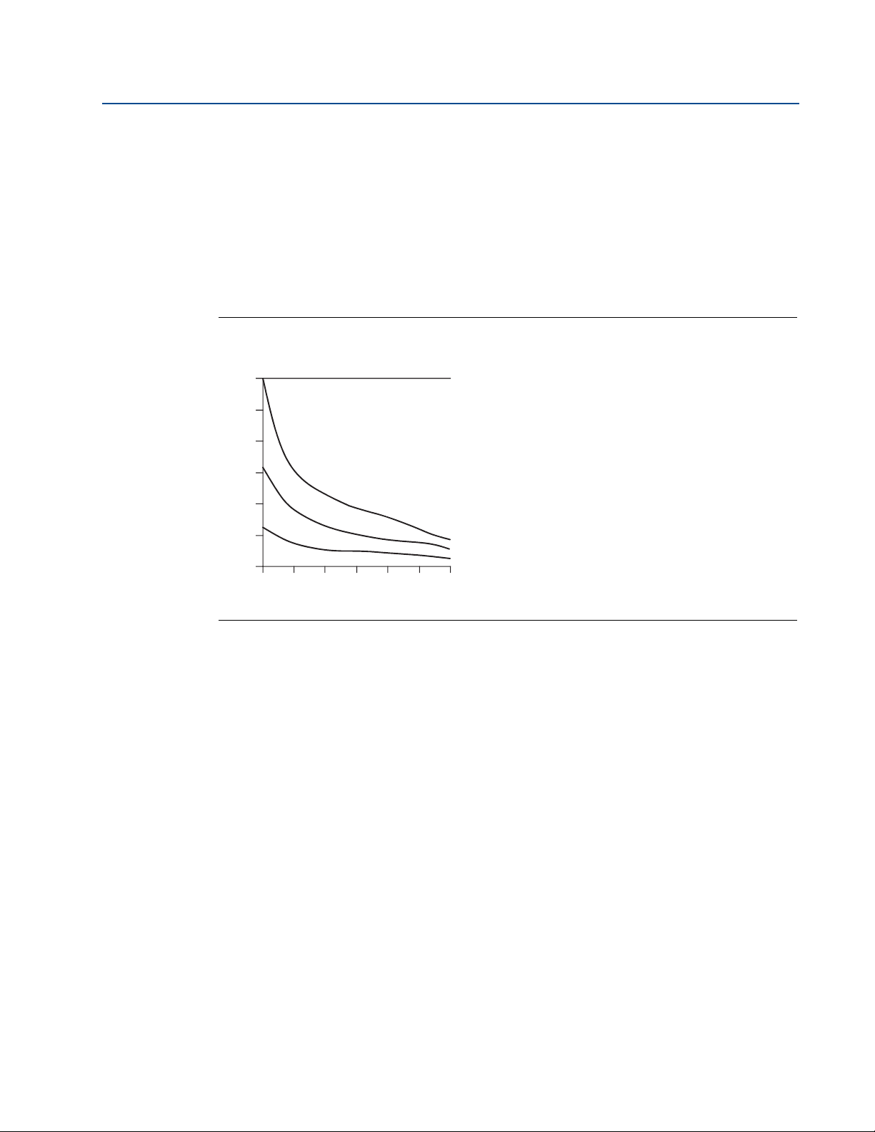
Temperature effects
The transmitter will operate within specifications for ambient temperatures between -40 °F and
185 °F (-40 °C and 85 °C). Heat from the process is transferred from the thermowell to the
transmitter housing. If the expected process temperature is near or above specification limits,
consider using additional thermowell lagging, and extension nipple, or a remote mounting
configuration to isolate the transmitter from the process.
Figure 1-1 provides an example of the relationship between transmitter housing temperature
rise and extension length.
Figure 1-1. Rosemount 148 transmitter connection head temperature rise vs. Extension
Reference Manual
00809-0100-4148, Rev CA
length.
4
Example
The transmitter specification limit is 85 °C. If the ambient temperature is 55 °C and the process
temperature to be measured is 800 °C, the maximum permissible connection head temperature
rise is the transmitter specification limit minus the ambient temperature (moves 85 °C to 55 °C),
or 30 °C.
In this case, an extension of 100 mm meets this requirement, but 125 mm provides a margin of
8 °C, thereby reducing any temperature effects in the transmitter.
Introduction
Page 11

Reference Manual
00809-0100-4148, Rev CA
1.4 Return of materials
To expedite the return process in North America, call the Emerson Process Management
National Response Center toll-free at 800-654-7768. This center, available 24 hours a day, can
assist with any needed information or materials.
The center will ask for the following information:
Product model
Serial numbers
The last process material to which the product was exposed
The center will provide:
A Return Material Authorization (RMA) number
Instructions and procedures that are necessary to return goods that were exposed to
hazardous substances
Note
If a hazardous substance is identified, a Material Safety Data Sheet (MSDS), required by law to be
available to people exposed to specific hazardous substances, must be included with the
returned materials.
Section 1: Introduction
April 2014
Outside of North America, contact a local Emerson Process Management representative.
1.5 Product recycling/disposal
Recycling of equipment and packaging should be taken into consideration and disposed of in
accordance with local and national legislation/regulations.
Introduction
5
Page 12

Section 1: Introduction
April 2014
Reference Manual
00809-0100-4148, Rev CA
6
Introduction
Page 13

Reference Manual
00809-0100-4148, Rev CA
Section 2 Installation
Safety messages . . . . . . . . . . . . . . . . . . . . . . . . . . . . . . . . . . . . . . . . . . . . . . . . . . . . . . . . . . . . . . . . . . . . page 7
Mounting . . . . . . . . . . . . . . . . . . . . . . . . . . . . . . . . . . . . . . . . . . . . . . . . . . . . . . . . . . . . . . . . . . . . . . . . . . page 8
Installation . . . . . . . . . . . . . . . . . . . . . . . . . . . . . . . . . . . . . . . . . . . . . . . . . . . . . . . . . . . . . . . . . . . . . . . . . page 9
Set the switches . . . . . . . . . . . . . . . . . . . . . . . . . . . . . . . . . . . . . . . . . . . . . . . . . . . . . . . . . . . . . . . . . . . . . page 11
Wiring . . . . . . . . . . . . . . . . . . . . . . . . . . . . . . . . . . . . . . . . . . . . . . . . . . . . . . . . . . . . . . . . . . . . . . . . . . . . . page 11
Power supply . . . . . . . . . . . . . . . . . . . . . . . . . . . . . . . . . . . . . . . . . . . . . . . . . . . . . . . . . . . . . . . . . . . . . . . page 15
2.1 Safety messages
Instructions and procedures in this section may require special precautions to ensure the safety
of the personnel performing the operations. Information that potentially raises safety issues is
indicated by a warning symbol . Please refer to the following safety messages before
performing an operation preceded by this symbol.
Section 2: Installation
April 2014
2.1.1 Warnings
Failure to follow these installation guidelines could result in death or serious injury:
Make sure only qualified personnel perform the installation.
Explosions could result in death or serious injury:
Do not remove the connection head cover in explosive atmospheres when the circuit
is live.
Before connecting a communicator in an explosive atmosphere, make sure the
instruments in the loop are installed in accordance with intrinsically safe or
non-incendive field wiring practices.
Verify that the operating atmosphere of the transmitter is consistent with the
appropriate hazardous locations certifications.
All connection head covers must be fully engaged to meet explosion-proof
requirements.
Process leaks could result in death or serious injury:
Do not remove the thermowell while in operation.
Install and tighten thermowells and sensors before applying pressure.
Electrical shock could cause death or serious injury:
Use extreme caution when making contact with the leads and terminals.
Installation
7
Page 14
Section 2: Installation
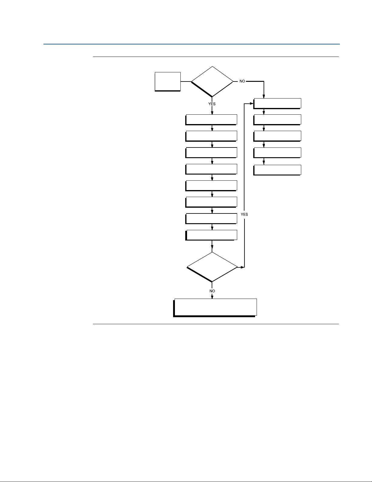
START
HERE
Bench
Configuration?
BASIC SETUP
Set Sensor Type
Set Number of Wires
Set Units
Set Range Values
Set Damping
VERIFY
Simulate Sensor
Input (Optional)
Within
Specifications?
Refer to
Section 4: Operation
and maintenance
FIELD INSTALL
Mount Transmitter
Wire
Tra ns mit te r
Power
Tra ns mit te r
FINISHED
April 2014
Figure 2-1. Installation flowchart
Reference Manual
00809-0100-4148, Rev CA
2.2 Mounting
Mount the transmitter at a high point in the conduit run to prevent moisture from draining into
the transmitter housing.
The Rosemount 148 installs:
In a connection head or universal head mounted directly on a sensor assembly
Apart from a sensor assembly using a universal head
To a DIN rail using an optional mounting clip
8
Installation
Page 15

Reference Manual
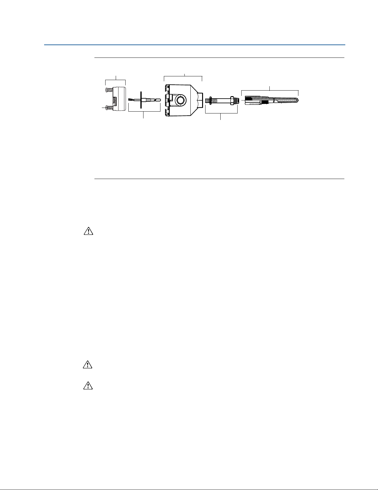
Tra ns mit te r
Mounting
Hardware
Rail Clip
00809-0100-4148, Rev CA
Mounting a Rosemount 148 to a DIN Rail
To attach a head mount transmitter to a DIN rail, assemble the appropriate rail mounting kit
(Part Number 00248-1601-0001) to the transmitter as shown in
Figure 2-2. Assembling rail clip hardware to a Rosemount 148.
2.3 Installation
Section 2: Installation
April 2014
Figure 2-2.
The Rosemount 148 can be ordered assembled to a sensor with the XA option code and
thermowell or as a stand-alone unit. If ordered without the sensor assembly, use the following
guidelines when installing the transmitter with an integral sensor assembly.
2.3.1 Typical European and Asia Pacific installation
Transmitter with DIN plate style sensor
1. Attach the thermowell to the pipe or process container wall. Install and tighten the
thermowell before applying process pressure.
2. Assemble the transmitter to the sensor. Push the transmitter mounting screws through
the sensor mounting plate and insert the snap rings (optional) into the transmitter
mounting screw groove.
3. Wire the sensor to the transmitter (see
4. Insert the transmitter-sensor assembly into the connection head. Thread the
transmitter mounting screw into the connection head mounting holes. Assemble the
extension to the connection head. Insert the assembly into the thermowell.
5. Slip the shielded cable through the cable gland.
6. Attach a cable gland into the shielded cable.
Figure 2-6 on page 13).
Installation
7. Insert the shielded cable leads into the connection head through the cable entry.
Connect and tighten the cable gland.
8. Connect the shielded power cable leads to the transmitter power terminals. Avoid
contact with sensor leads and sensor connections. (See
page 15
9. Install and tighten the connection head cover. Enclosure covers must be fully engaged
to meet explosion-proof requirements.
for instructions on grounding the shield wire.)
“Ground the transmitter” on
9
Page 16
Section 2: Installation
A
D
B
C
E
F
April 2014
Figure 2-3. Typical European and Asia Pacific installation
A . Rosemount 148 Transmitter
B . Connection Head
C . Thermowell
D . Transmitter Mounting Screws
E . Integral Mount Sensor with Flying Leads
F . Extension
2.3.2 Typical North and South American installation
Reference Manual
00809-0100-4148, Rev CA
Transmitter with threaded sensor
1. Attach the thermowell to the pipe or process container wall. Install and tighten
thermowells before applying process pressure.
2. Attach necessary extension nipples and adapters to the thermowell. Seal the nipple and
adapter threads with silicone tape.
3. Turn the sensor into the thermowell until it is secure. Install drain seals if required for
severe environments or to satisfy code requirements.
4. Pull the sensor wiring leads through the universal head and transmitter. Mount the
transmitter in the universal head by threading the transmitter mounting screws into
the universal head mounting holes.
5. Mount the transmitter-sensor assembly into the thermowell. Seal adapter threads with
silicon tape.
6. Install conduit for field wiring to the conduit entry of the universal head. Seal conduit
threads with silicon tape.
7. Pull the field wiring leads through the conduit into the universal head. Attach the sensor
and power leads to the transmitter. Avoid contact with other terminals.
8. Install and tighten the universal head cover. Enclosure covers must be fully engaged to
meet explosion-proof requirements.
10
Installation
Page 17
Reference Manual
A
B
C
D
E
00809-0100-4148, Rev CA
Figure 2-4. Typical North and South American installation
A . Threaded Thermowell
B . Threaded Style Sensor
C . Standard Extension
D . Universal Head
E . Conduit Entry
2.4 Set the switches
Section 2: Installation
April 2014
2.4.1 Failure mode
As part of normal operation, each transmitter continuously monitors its own performance. This
automatic diagnostics routine is a timed series of checks repeated continuously. If diagnostics
detect an input sensor failure or a failure in the transmitter electronics, the transmitter drives its
output to low or high alarm depending on the failure mode configuration. If the sensor (process)
temperature value is out of range, the transmitter outputs default saturation values. Low end
saturation levels are either 3.90 or 3.80 mA and the high end saturation level is 20.5 mA.
Corresponding NAMUR compliant operation levels are 3.80 and 20.5 mA. These values are also
custom configurable by the factory or using the Rosemount 148 PC Programmer interface. See
“
Section 3: Configuration” on page 19 for instructions on how to change the alarm and saturation
levels with the 148 PC Programmer.
Note
Microprocessor failures cause high alarm regardless of alarm direction (high or low) choice.
The values to which the transmitter drives its output in failure mode depend on whether it is
configured to standard, NAMUR-compliant, or custom operations. See (
NAMUR-compliant operation parameters.
2.5 Wiring
All power to the transmitter is supplied over the signal wiring. Use ordinary copper wire of
sufficient size to ensure that the voltage across the transmitter power terminals does not drop
below 12.0 V DC. Verify that the operating atmosphere of the transmitter is consistent with the
appropriate hazardous locations certifications. Use extreme caution when making contact with
the leads and terminals.
★) for standard and
Installation
If the sensor is installed in a high-voltage environment and a fault condition or installation error
occurs, the sensor leads and transmitter terminals could carry lethal voltages. Use extreme
caution when making contact with the leads and terminals.
11
Page 18

Section 2: Installation
44.0 (1.7)
33 (1.3)
12.9 (0.51)
24.5 (0.97)
Sensor Terminals
Power/Communication
Ter mi na ls
April 2014
Note
Do not apply high voltage (e.g., AC line voltage) to the transmitter terminals, since abnormally
high voltage can damage the unit. Sensor and transmitter power terminals are rated to 42.4 V
DC). Use extreme caution w hen making contact with the leads and terminals.
The transmitters will accept inputs from a variety of RTD and thermocouple types. Refer to
Figure 2-6 on page 13 when making sensor connections.
Use the following steps to wire the transmitter:
1. Remove the terminal block cover, if applicable.
2. Connect the positive power lead to the “+” terminal. Connect the negative power lead
3. Tighten the terminal screws.
4. Reattach and tighten the cover, if applicable. All connection head covers must be fully
to the “-” terminal. See
Figure 2-5 on page 12. Use extreme caution when making contact
with the leads and terminals.
engaged to met explosion-proof requirements.
Reference Manual
00809-0100-4148, Rev CA
5. Apply power (see “Power supply”)
Figure 2-5. Rosemount 148 Wiring
Power, Communication and Sensors Terminals
Note: Signal loop may be grounded at any single point or left ungrounded.
2.5.1 Sensor connections
The Rosemount 148 is compatible with a number of RTD and thermocouple sensor types.
Figure 2-6 shows the correct input connections to the sensor terminals on the transmitter. To
ensure a proper sensor connection, anchor the sensor lead wires into the appropriate
compression terminals and tighten the screws. Use extreme caution when making contact with
the leads and terminals.
12
Installation
Page 19

Reference Manual
1234234 12 34 1234
1
2-wire
RTD and ⍀
3-wire*
RTD
and ⍀
T/C
4-wire RTD
and ⍀
00809-0100-4148, Rev CA
Figure 2-6. Sensor wiring diagrams
Thermocouple
The thermocouple can be connected directly to the transmitter. Use appropriate thermocouple
extension wire if mounting the transmitter remotely from the sensor.
Section 2: Installation
Rosemount 148 Sensor Connections Diagram
* Emerson Process Management provides 4-wire sensors for all single element RTDs. Use these RTDs in 3-wire
configurations by leaving the unneeded leads disconnected and insulated with electrical tape.
April 2014
RTD or ohm inputs
The Rosemount 148 will accept a variety of RTD configurations, including 2-wire, 3-wire, and
4-wire designs. If the transmitter is mounted remotely from a 3-wire or 4-wire RTD, it will
operate within specifications, without recalibration, for lead wire resistances of up to 60 ohms
per lead (equivalent to 6,000 feet of 20 AWG wire). In this case, the leads between the RTD and
transmitter should be shielded. If using only two leads, both RTD leads are in series with the
sensor element, so significant errors can occur if the lead lengths exceed three feet of 20 AWG
wire (approximately 0.05 °C/ft). For longer runs, attach a third of fourth lead as described above.
Sensor lead wire resistance effect - RTD input
When using a 4-wire RTD, the effect of lead resistance is eliminated and has no impact on
accuracy. However, a 3-wire sensor will not fully cancel lead resistance error because it cannot
compensate for imbalances in resistance between the lead wires. Using the same type of wire
on all three lead wires will make a 3-wire RTD installation as accurate as possible. A 2-wire sensor
will produce the largest error because it directly adds the lead wire resistance to the sensor
resistance. For 2- and 3-wire RTDs, an additional lead wire resistance error is induced with
ambient temperature variations. The table and the examples shown below help quantify these
errors.
Table 2-1. Examples of approximate basic error.
Sensor input Approximate basic error
Installation
4-wire RTD None (independent of lead wire resistance)
3-wire RTD
2-wire RTD 1.0 in reading per ohm of lead wire resistance
± 1.0 in reading per ohm of unbalanced lead wire resistance
(Unbalanced lead wire resistance = maximum imbalance
between any two leads.)
13
Page 20

Section 2: Installation
Basic Error
Imbalance of Lead Wires
PtRo
------------------------------------------------------------ ----- -
=
Error due to amb. temp. variation
Cu
T
amb
Imbalance of Lead Wires
Pt
Ro
---------------------------------------------------------------- ---------------------------------------------------------
=
Basic error
0.5
0.00385 / C100
----------------------------------------------------------- ---------------------- -
1.3 C==
Error due to amb. temp. var. of 25 °C
0.0039 / C25 C 0.5
0.00385 / C100
----------------------------------------------------------- --------------------------------------------
0.13·C==
Basic Error
Lead Wire Resistance
PtRo
----------------------------------------------------------
=
Error due to amb. temp. variation
Cu
T
amb
Lead Wire Resistance
Pt
Ro
------------------------------------------------------------- ----------------------------------------------------
=
Basic error
7.5
0.00385 / C100
------------------------------------------------------------ --------------------- -
19.5 C==
Error due to amb. temp. var. of 25 °C
0.0039 / C25 C 7.5
0.00385 / C100
--------------------------------------------------------------- ----------------------------------------
1.9 C==
April 2014
Examples of approximate lead wire resistance effect
calculations
Given:
Total cable length: 150 m
Imbalance of the lead wires at 20 °C: 0.5
Resistance/length (18 AWG Cu): 0.025 /m °C
Temperature coefficient of Cu (Cu): 0.039 / °C
Temperature coefficient of Pt(Pt): 0.00385 / °C
Reference Manual
00809-0100-4148, Rev CA
Change in Ambient Temperature (T
): 25 °C
amb
RTD Resistance at 0 °C (Ro): 100 (for Pt 100 RTD)
Pt100 4-wire RTD: No lead wire resistance effect.
Pt100 3-wire RTD:
Lead wire imbalance seen by the transmitter = 0.5
Pt100 2-wire RTD:
14
Lead wire resistance seen by the transmitter = 150 m × 2 wires × 0.025
/m = 7.5
Installation
Page 21

Reference Manual
4–20 mA loop
Sensor Wires
Shield ground point
Tra ns mit te r
00809-0100-4148, Rev CA
2.6 Power supply
The power supplied to the transmitter should not drop below the transmitter lift-off voltage of
12 V DC.
2.6.1 Surges/transients
The transmitter will withstand electrical transients of the energy level encountered in static
discharges or induced switching transients. However, high-energy transients, such as those
induced in wiring from nearby lightening strikes, welding, heavy electrical equipment, or
switching gears, can damage both the transmitter and the sensor. To protect against
high-energy transients, install the transmitter into a suitable connection head with the
Rosemount 470 Transient Protector. Refer to the Rosemount 470 Transient Protector Product
Data Sheet (Document Number 00813-0100-4191) for further information.
2.6.2 Ground the transmitter
The transmitter will operate with the current signal loop either floating or grounded. However,
the extra noise in floating systems affects many types of readout devices. If the signal appears
noisy or erratic, grounding the current signal loop at a single point may solve the problem. The
best place to ground the loop is at the negative terminal of the power supply. Do not ground the
current signal loop at more than one point.
Section 2: Installation
April 2014
The transmitter is electrically isolated at 500 V AC rms (707 V DC) at 50/60 Hz, so the input
circuit may also be grounded at any single point. When using a grounded thermocouple, the
grounded junction serves as this point.
Note
Do not ground the signal wire at both ends.
Ungrounded thermocouple, and RTD/ohm inputs
Each process installation has different requirements for grounding. Use the grounding options
recommended by the facility for the specific sensor type, or begin with grounding Option 1 (the
most common).
Option 1:
1. Connect sensor wiring shield to the transmitter housing (only if the housing is
grounded).
2. Ensure the sensor shield is electrically isolated from surrounding fixtures that may be
grounded.
3. Ground signal wiring shield at the power supply end.
Figure 2-7. Grounded housing option (most common)
Installation
15
Page 22

Section 2: Installation
Sensor Wires
4–20 mA loop
Shield ground point
Connect shields together, electrically isolated from the transmitter
Tra ns mit te r
4–20 mA loopSensor Wires
Shield ground point
Transmitter
April 2014
Option 2 (for ungrounded housing):
1. Connect signal wiring shield to the sensor wiring shield.
2. Ensure the two shields are tied together and electrically isolated from the transmitter
3. Ground shield at the power supply end only.
4. Ensure that the sensor shield is electrically isolated from the surrounding grounded
Figure 2-8. Ungrounded housing
Reference Manual
00809-0100-4148, Rev CA
housing.
fixtures.
Option 3:
1. Ground sensor wiring shield at the sensor, if possible.
2. Ensure that the sensor wiring and signal wiring shields are electrically isolated from the
transmitter housing.
3. Do not connect the signal wiring shield to the sensor wiring shield.
4. Ground signal wiring shield at the power supply end.
Figure 2-9. Ground sensor wiring
16
Installation
Page 23

Reference Manual
4–20 mA loop
Sensor Wires
Shield ground point
Tra ns mit te r
00809-0100-4148, Rev CA
Grounded thermocouple inputs
Option 4:
1. Ground sensor wiring shield at the sensor.
2. Ensure that the sensor wiring and signal wiring shields are electrically isolated from the
3. Do not connect the signal wiring shield to the sensor wiring shield.
4. Ground signal wiring shield at the power supply end.
Figure 2-10. Grounded thermocouple input option
Section 2: Installation
April 2014
transmitter housing.
Installation
17
Page 24

Section 2: Installation
April 2014
Reference Manual
00809-0100-4148, Rev CA
18
Installation
Page 25

Reference Manual
00809-0100-4148, Rev CA
Section 3 Configuration
Safety messages . . . . . . . . . . . . . . . . . . . . . . . . . . . . . . . . . . . . . . . . . . . . . . . . . . . . . . . . . . . . page 19
Rosemount 148 PC Programmer . . . . . . . . . . . . . . . . . . . . . . . . . . . . . . . . . . . . . . . . . . . . . . page 20
3.1 Safety messages
Instructions and procedures in this section may require special precautions to ensure the safety
of the personnel performing the operations. Information that potentially raises safety issues is
indicated by a warning symbol ( ). Please refer to the following safety messages before
performing an operation preceded by this symbol.
3.1.1 Warnings
Section 3: Configuration
April 2014
Failure to follow these installation guidelines could result in death or serious injury:
Make sure only qualified personnel perform the installation.
Explosions could result in death or serious injury:
Do not remove the connection head cover in explosive atmospheres when the
circuit is live.
Before connecting a communicator in an explosive atmosphere, make sure the
instruments in the loop are installed in accordance with intrinsically safe or
non-incendive field wiring practices.
When sending or requesting data that would disrupt the loop or change the output of
the transmitter, set the process application loop to manual.
Verify that the operating atmosphere of the transmitter is consistent with the
appropriate hazardous locations certifications.
All connection head covers must be fully engaged to meet
explosion-proof requirements.
Process leaks could result in death or serious injury:
Do not remove the thermowell while in operation.
Install and tighten thermowells and sensors before applying pressure
Electrical shock could cause death or serious injury:
Use extreme caution when making contact with the leads and terminals.
Configuration
19
Page 26

Section 3: Configuration
April 2014
3.2 Rosemount 148 PC Programmer
The Rosemount 148 must be configured for certain basis variables to operate. In many cases, all
of these variables are pre-configured at the factory. Configuration may be required if the
transmitter is not configured or if the configuration variables need revision.
Configuration consists of testing the transmitter and verifying transmitter configuration data.
The Rosemount 148 must be configured before installation. This can be done two ways:
ordering factory-configuration by Emerson, or using the Rosemount 148 PC Programmer
interface in a bench configuration setting.
3.2.1 PC Programmer software installation
The Rosemount 148 PC Programmer exchanges information with the transmitter in a bench
configuration setting through a personal computer and interface box. See below for detailed
instructions on installing the programming software.
1. Install the Rosemount 148 PC Programmer software.
– Place the Rosemount 148 PC Programmer CD_ROM into the drive
Reference Manual
00809-0100-4148, Rev CA
– Run setup.exe from Windows NT, 2000, or XP
2. When first using the Rosemount 148 PC software, configure the appropriate COM ports
by choosing Port Settings from the Communicate menu.
3. Install MACTek Modem drivers completely before beginning bench configuration on
the Rosemount 148 system.
Note
The software defaults to the first available COM port.
3.2.2 PC Programmer hardware setup
The Rosemount 148 PC Programming Kit includes configuration software and a communication
modem. The Rosemount 148 device will need an external power supply of 12-42.4 Vdc for
configuration.
1. Hook up the transmitter and a load resistor (250 - 1100 ohms) wired in series with the
power supply.
2. Attach the Modem in parallel with the load resistor and connect it to the PC.
Please see Tab l e 3 - 1 for Spares Kit and re-order numbers.
Table 3-1. Rosemount 148 Programming Kit spare part numbers
20
Product description Part number
Programming Software (CD) 00148-1601-0002
Rosemount 148 Programmer Kit - USB 00148-1601-0003
Rosemount 148 Programmer Kit - Serial 00148-1601-0004
The device can be configured from the main screen, and will also show the current transmitter
status. The following pages detail the settings that can be configured on the Rosemount 148.
Configuration
Page 27

Reference Manual
00809-0100-4148, Rev CA
Section 3: Configuration
3.2.3 Configuring with the Rosemount 148 PC Programmer
In order to operate properly, the Rosemount 148 has basic variables that need to be configured.
Some of the variables are factory configured, however, some of the variables may need to be
initially set up or revised. The first two tabs on the main screen are Basic and Advanced Settings,
which include all of the configuration variables that can be set for the Rosemount 148. Any
changes to the configuration must be sent to the transmitter by clicking the Send to Transmitter
button on the right of the screen. The current configuration of the connected 148 may be
viewed by clicking the Load From Transmitter button.
Transmitter identification
The Tag variable is the easiest way to identify/distinguish between transmitters. It can be used
to label transmitters electronically according to the requirements of the application. The tag
may be up to eight characters in length, and does not impact the measurement of the
transmitter.
Sensor configuration
April 2014
The following sensors indicate the sensor type and the number of wires to be connected:
2-, 3-, or 4-wire Pt 100: = 0.00385 /°C
2-, 3-, or 4-wire Pt 100: = 0.003916 /°C
2-, 3-, or 4-wire Ni 120 nickel RTDs
2-, 3-, or 4-wire Cu 10 RTDs
IEC/NIST/DIN Type B, J, K, N, R, S Thermocouples
2-, 3-, or 4-wire 0 - 2000 ohms
A complete line of temperature sensors, thermowells, and accessory mounting hardware is
available from Emerson Process Management.
Output configuration
The Output Configuration area allows the user to set the desired measurement values for the
transmitter:
Degrees Celsius
Degrees Fahrenheit
Degrees Rankine
Kelvin
Ohms
Configuration
Millivolts
The 4 mA and 20 mA measurement point will need to be set to determine the analog output
based on the temperature reading.
The Lower and Upper Range Limit of the sensor type selected above can also be viewed.
21
Page 28

Section 3: Configuration
PNP–1e
t–
T
----
–
+
P =previous damped value
N =new sensor value
T = damping time constant
U =update rate
April 2014
Damping
The Damping value changes the response time of the transmitter to smooth variations in the
readings caused by rapid changes in input. Determine the appropriate damping setting based
on the necessary response time, signal stability, and other requirements of the loop dynamics of
the system. The default damping value is 5.0 seconds and can be reset to any value between 0
and 32 seconds.
The value chosen for damping affects the response time of the transmitter. When set to zero (or
disabled), the damping function is off and the transmitter output reacts to changes in input as
quickly as the intermittent sensor algorithm allows (refer to “*”) for a description of the
intermittent sensor algorithm. Increasing the damping value increases the transmitter response
time.
With damping enabled, the transmitter outputs values according to the following relationship.
At time t
Damping Value =
Reference Manual
00809-0100-4148, Rev CA
At the time which the damping time constant is set, the transmitter output is at 63% of the
input changes and it continues to approach the input according to the damping equation above.
After one damping time constant following a sensor input step change, the transmitter output
will be 63.2% of that change. The output will continue to approach the input according to the
damping equation above.
For example, as illustrated in *, if the temperature undergoes a step change from 100 ° to 100 °,
and the damping is set to 5.0 seconds, the transmitter calculates and reports a new reading
using the damping equation. At 5.0 seconds, the transmitter outputs 106.3 °, or 63.2% of the
input change, and the output continues to approach the input curve according to the above
equation.
Figure 3-1. Change in input vs. Change in output with Damping set to five seconds
22
Configuration
Page 29

Reference Manual
00809-0100-4148, Rev CA
Alarm and saturation
Alarm Direction, Low Alarm Level, High Alarm Level, Low Saturation, and High Saturation values
can be set here. Rosemount and NAMUR standard values can be found on Ta b le A - 1 * or
user-configured values may be entered. The guidelines are as follows:
Low Alarm value must be between 3.50 and 3.75 mA
High Alarm value must be between 21.0 and 23.0 mA
Low Saturation level must be between the Low Alarm value plus 0.1 mA and 3.9 mA.
The High Saturation level must be between 20.5 mA and the High Alarm value minus
See “Failure mode” for Failure Mode considerations.
50/60 Hz selection
The 50/60 Hz Selection sets the transmitter electronic filter to reject the frequency of the AC
power supply in the plant.
Section 3: Configuration
April 2014
Example: The Low Alarm value has been set to 3.7 mA, so the Low Saturation level (S) must
be 3.8 - 3.9 mA.
0.1 mA. Example: The High Alarm value has been set to 20.8 mA, so the Low Saturation level
(S) must be 20.5 - 20.7 mA.
Write protect
Write Protect safeguards the transmitter configuration data from accidental or unwarranted
changes.
3.2.4 Information
The transmitter information tab can be selected from the main stat up screen, and lists the
transmitter information variables that can be viewed. The Refresh button must be clicked to
update the view of the current state of the transmitter.
Sensor temperature
The sensor temperature readings are displayed in the units set in the Basic Settings.
Analog output (mA)
Displays the transmitter output, read by the host system, in milliamperes.
Transmitter temperature
Shows the reading used by the onboard RTD to compensate the cold junction of
thermocouples.
Configuration
Status indicator buttons
Two buttons that indicate if the device is in Sensor Malfunction or Transmitter Malfunction.
Device identification
This shows revisions for the Software, Hardware and Final Assembly Number.
23
Page 30

Section 3: Configuration
April 2014
Reference Manual
00809-0100-4148, Rev CA
24
Configuration
Page 31

Reference Manual
00809-0100-4148, Rev CA
Section 4: Operation and Maintenance
Section 4 Operation and Maintenance
Safety messages . . . . . . . . . . . . . . . . . . . . . . . . . . . . . . . . . . . . . . . . . . . . . . . . . . . . . . . . . . . . page 25
Hardware . . . . . . . . . . . . . . . . . . . . . . . . . . . . . . . . . . . . . . . . . . . . . . . . . . . . . . . . . . . . . . . . . . page 26
4.1 Safety messages
Instructions and procedures in this section may require special precautions to ensure the safety
of the personnel performing the operations. Information that potentially raises safety issues is
indicated by a warning symbol ( ). Please refer to the following safety messages before
performing an operation preceded by this symbol.
4.1.1 Warnings
April 2014
Failure to follow these installation guidelines could result in death or serious injury:
Make sure only qualified personnel perform the installation.
Explosions could result in death or serious injury:
Do not remove the connection head cover in explosive atmospheres when the
circuit is live.
Before connecting a Field Communicator in an explosive atmosphere, make sure the
instruments in the loop are installed in accordance with intrinsically safe or
non-incendive field wiring practices.
When sending or requesting data that would disrupt the loop or change the output of
the transmitter, set the process application loop to manual.
Verify that the operating atmosphere of the transmitter is consistent with the
appropriate hazardous locations certifications.
All connection head covers must be fully engaged to meet explosion-proof
requirements.
Process leaks could result in death or serious injury:
Do not remove the thermowell while in operation.
Install and tighten thermowells and sensors before applying pressure
Electrical shock could cause death or serious injury:
Use extreme caution when making contact with the leads and terminals.
Operation and Maintenance
25
Page 32

Section 4: Operation and Maintenance
April 2014
4.2 Hardware
The Rosemount 148 has no moving parts and requires minimal scheduled maintenance.
4.2.1 Maintenance
Sensor checkout
To determine whether the sensor is at fault, replace it with another sensor or connect a test
sensor locally at the transmitter to test remote sensor wiring. Do not remove the thermowell
while in operation. Select any standard, off-the-shelf sensor for use with a Rosemount 148 or
consult the factory for a replacement special sensor and transmitter combination.
4.2.2 Diagnostic messages
If a malfunction is suspected, follow the procedures described in Ta b le 4 - 1 to verify that
transmitter hardware and process connections are in good working order. Under each of the
three major symptoms, specific suggestions are offered for solving the problem.
Reference Manual
00809-0100-4148, Rev CA
Table 4-1. Rosemount 148 troubleshooting chart
Symptom Potential source Corrective action
Check for a sensor open or short circuit.
High Output
Sensor Input Failure
or Connection
Loop Wiring
Check the process variable to see if it is out of
range.
Check for dirty or defective terminals,
interconnecting pins, or receptacles.
Check the output voltage of the power supply at
the transmitter terminals. It should be 12.0 to
42.4 V dc (over entire 3.75 to 23 mA operating
Power Supply
Check for adequate voltage to the transmitter. It
range).
should be 12.0 to 42.4 V dc at the transmitter
terminals (over entire 3.75 to 23 mA operating
range).
Erratic
Output Loop Wiring
Low Output
or No Output Sensor Element
Check for intermittent shorts, open circuits, and
multiple grounds.
Check the process variable to see if it is out of
range.
Check for adequate voltage to the transmitter. It
should be 12.0 to 42.4 V dc (over entire 3.75 to
23 mA operating range).
26
Loop Wiring
Check for shorts and multiple grounds.
Check for proper polarity at the signal terminal.
Check the loop impedance.
Check wire insulation to detect possible shorts
to ground.
Operation and Maintenance
Page 33

Reference Manual
00809-0100-4148, Rev CA
Appendix A: Specifications and reference data
Appendix A Specifications
Transmitter specifications . . . . . . . . . . . . . . . . . . . . . . . . . . . . . . . . . . . . . . . . . . . . . . . . . . . . . . . . . . . . page 27
Dimensional drawings . . . . . . . . . . . . . . . . . . . . . . . . . . . . . . . . . . . . . . . . . . . . . . . . . . . . . . . . . . . . . . . page 32
Ordering information . . . . . . . . . . . . . . . . . . . . . . . . . . . . . . . . . . . . . . . . . . . . . . . . . . . . . . . . . . . . . . . . page 34
A.1 Transmitter specifications
A.1.1 Functional specifications
Inputs
User-selectable. See “Transmitter accuracy and ambient temperature effects ” for sensor options.
April 2014
Outputs
2-wire 4–20 mA, linear with temperature or input.
Isolation
Input/output isolation tested to 500 V AC rms (707 V DC) at 50/60 Hz.
Power supply
An external power supply is required. The transmitter operates on 12.0 to 42.4 V DC transmitter
terminal voltage.
Humidity limits
0 - 95% relative humidity, non-condensing
NAMUR recommendations
The Rosemount 148 meets the following NAMUR recommendations:
NE 21 - Electromagnetic compatibility (EMC) for Process and Laboratory Apparatus
NE 43 - Standard of the signal level breakdown information of digital transmitters
Specifications
Transient protection
The optional Rosemount 470 prevents damage from transients induced by lightening, welding,
heavy electrical equipment, or switch gears. Refer to the Rosemount 470 Product Data Sheet
(Document Number 00813-0100-4191) for more information.
27
Page 34

Appendix A: Specifications and reference data
April 2014
Temperature limits
Operating limit
–40 to 185 °F (–40 to 85 °C)
Storage limit
–58 to 248 °F (–50 to 120 °C)
Turn-on time
Performance within specifications in less than 5.0 seconds after power is applied to transmitter,
when damping value is set to zero seconds.
Update rate
Less than 0.5 seconds
Custom alarm and saturation levels
Reference Manual
00809-0100-4148, Rev CA
Custom configuration of alarm and saturation levels is available by using the 148 PC
Programmer.
Software detected failure mode
The values at which the transmitter drives its output in failure mode depends on device
configuration. The device can be configured to meet NAMUR-compliant (NAMUR
recommendation NE 43) operation. The values for standard and NAMUR-compliant operation
are as follows:
Table A-1. Operation Parameters
Standard
Linear Output: 3.9 I 20.5 3.8 I 20.5
Fail High: 21 I 23 (default) 21 I 23
Fail Low: I 3.75 I 3.6
(1) Measured in milliamperes.
Certain hardware failures, such as microprocessor failures, will always drive the output to
greater than 23 mA.
A.1.2 Physical specifications
(1)
NAMUR NE43- Compliant
(1)
28
Communication connections
Communication Terminal: Clips permanently fixed to the terminals.
Specifications
Page 35

Reference Manual
00809-0100-4148, Rev CA
Materials of construction
Electronics housing
Noryl
Universal (option codes U and H) heads
Housing: Low-copper aluminum (option code U)
Paint: Polyurethane
Cover O-Ring: Buna-N
Mounting
The Rosemount 148 installs in a connection head or universal head mounted directly on a
sensor assembly or apart from a sensor assembly using a universal head. The Rosemount 148
can also mount to a DIN rail using an optional mounting clip.
Weight
®
glass reinforced
Stainless Steel (option code H)
Appendix A: Specifications and reference data
April 2014
Code Options Weight
148 Head Mount Transmitter 42 g (1.5 oz)
U Universal Head 520 g (18.4 oz)
H Universal Head (SST) 1700 g (60 oz)
Enclosure ratings
The Universal (option codes U and H) Heads are NEMA 4X, IP66, and IP68. The Universal Head
1
with
/2-in. NPT threads is CSA Enclosure Type 4X.
A.1.3 Performance specifications
EMC (ElectroMagnetic Compatibility) NAMUR NE21 Standard
The Rosemount 148 meets the requirements for NAMUR NE21 Rating
Susceptibility Parameter Influence
ESD
Radiated •80 – 1000 MHz at 10 V/m AM None
Burst •1 kV for I.O. None
Surge
Conducted • 150 kHz to 80 MHz at 10 V None
•6 kV contact discharge
•8 kV air discharge
•0.5 kV line–line
•1 kV line–ground
None
None
Specifications
CE mark
The Rosemount 148 meets all requirements listed under IEC 61326: Amendment 1, 2006
29
Page 36

Appendix A: Specifications and reference data
1234234 12 34 1234
1
2-wire
RTD and ⍀
3-wire*
RTD
and ⍀
4-wire
RTD
and ⍀
T/C
April 2014
Power supply effect
Less than ±0.005% of span per volt
Vibration effect
The Rosemount 148 is tested to the following specifications with no effect on performance:
Frequency Vibration
10 to 60 Hz 0.21 mm displacement
60 to 2000 Hz 3 g peak acceleration
Stability
For RTD and thermocouple inputs, the transmitter will have a stability of ±0.15% of reading or
0.15 °C (whichever is greater) for twelve months.
Sensor connections
Rosemount 148 Sensor connections diagram
Reference Manual
00809-0100-4148, Rev CA
* Rosemount Inc. provides 4-wire sensors for all single element RTDs. You can use these
RTDs in 3-wire configurations by leaving the unneeded leads disconnected and insulated
with electrical tape.
Transmitter accuracy and ambient temperature effects
Note
The accuracy and ambient temperature effect is the greater of the fixed and percent of span
values (see example below).
30
Specifications
Page 37

Reference Manual
0.320.09
2
+ 0.31 C=
00809-0100-4148, Rev CA
Appendix A: Specifications and reference data
Table A-2. Rosemount 148 Transmitter Input Options, Accuracy, and Ambient Temperature Effects
April 2014
Temperature Effects per 1.0 °C
(1.8 °F) Change in Ambient
Temperature
Fixed
(2)
% of
Span
Sensor
Transmitter In put Ran ges
(1)
°C °F Fixed
Accuracy
% of
Span
2-, 3-, 4-wire RTDs
(3)
Pt 100
Pt 100
Ni 120
Cu 10
Thermocouples
Type B
Type J
Type K
Type N
Type R
Type S
( = 0.00385)
(4)
( = 0.003916)
(5)
(6)
(7)
(8)(9)
(8)
(8)(10)
(8)
(8)
(8)
–200 to 850 –328 to 1562 0.3 °C (0.54 °F) ±0.15 0.009 °C (0.016 °F) ±0.006
–200 to 645 –328 to 1193 0.3 °C (0.54 °F) ±0.15 0.009 °C (0.016 °F) ±0.006
–70 to 300 –94 to 572 0.2 °C (0.36 °F) ±0.15 0.006 °C (0.011 °F) ±0.006
–50 to 250 –58 to 482 3 °C (5.40 °F) ±0.15 0.09 °C (0.16 °F) ±0.006
100 to 1820 212 to 3308 2.3 °C (4.05 °F) ±0.15 0.084 °C (0.150 °F) ±0.006
–180 to 760 –292 to 1400 0.8 °C (1.35 °F) ±0.15 0.03 °C (0.054 °F) ±0.006
–180 to 1372 –292 to 2502 0.8 °C (1.35 °F) ±0.15 0.03 °C (0.054 °F) ±0.006
–200 to 1300 –328 to 2372 1.2 °C (2.16 °F) ±0.15 0.03 °C (0.054 °F) ±0.006
0 to 1768 32 to 3214 1.8 °C (3.24 °F) ±0.15 0.09 °C (0.16 °F) ±0.006
0 to 1768 32 to 3214 1.5 °C (2.70 °F) ±0.15 0.09 °C (0.16 °F) ±0.006
2-, 3-, 4-wire Ohm Input 0 to 2000 ohms 1.1 ohm ±0.15 0.042 ohm ±0.006
(1) Input ranges are for transmitter only. Actual sensor (RTD or Thermocouple) operating ranges may be more limited.
(2) Change in ambient is with reference to the calibration temperature of the transmitter at 68 °F (20 °C) from factory.
(3) IEC 751, 1995.
(4) JIS 1604, 1981.
(5) Edison Curve No. 7.
(6) Edison Copper Winding No. 15.
(7) Total accuracy for thermocouple measurement: sum of accuracy +0.5 °C.
(8) NIST Monograph 175, IEC 584.
(9) Fixed accuracy for NIST Type B is ±5.4 °F (±3.0 °C) from 212 to 572 °F (100 to 300 °C).
(10)Fixed accuracy for NIST Type K is ±1.3 °F (±0.7 °C) from -292 to -130 °F (-130 to -90 °C).
Specifications
Transmitter accuracy example
When using a Pt 100 (a = 0.00385) sensor input with a 0 to 100 °C span, use the greater of the
two calculated values. In this case the accuracy would be +/-0.3 °C.
Transmitter temperature effects example
Transmitters can be installed in locations where the ambient temperature is between –40 and
85 °C (–40 and 185 °F). In order to maintain excellent accuracy performance, each transmitter is
individually characterized over this ambient temperature range at the factory.
When using a Pt 100 (a = 0.00385) sensor input with a 0–100 °C span at 30 °C ambient
temperature:
Temperature Effects: 0.009 °C x (30 - 20) = 0.09 °C
Total transmitter error
Worst Case Transmitter Error: Accuracy + Temperature Effects = 0.3 °C + 0.09 °C = 0.39 °C
Total Probable Transmitter Error:
31
Page 38

Appendix A: Specifications and reference data
44 (1.7)
33 (1.3)
12.9 (0.51)
24.5
(0.97)
95
(3.74)
96 (3.76)
112 (4.41)
SST “U” Bolt
Mounting,
2-inch Pipe
Approval
Label
75
(2.93)
104
(4.09)
100
(3.93)
78
(3.07)
Approval Label
84 (3.331)
118
April 2014
A.2 Dimensional drawings
Rosemount 148 Transmitter
(enlarged)
Reference Manual
00809-0100-4148, Rev CA
Dimensions are in millimeters (inches).
Enclosures
Universal head
(option codes H and U)
Dimensions are in millimeters (inches).
32
(1) A “U” Bolt is shipped with each universal head unless a sensor is ordered assembled to the enclosure. However, since the head can be
integrally mounted to the sensor it may not need to be used.
(2) Consult factory for ordering availability.
(1)
Connection head
(2)
BUZ and polypropylene
heads
(2)
Specifications
Page 39

Reference Manual
N
U
25 (1.0)
BUZ Connection Head
N
U
40 (1.6)
60 (2.3)
Connection Head
U
N
60 (2.3)*
Universal Head
00809-0100-4148, Rev CA
Appendix A: Specifications and reference data
April 2014
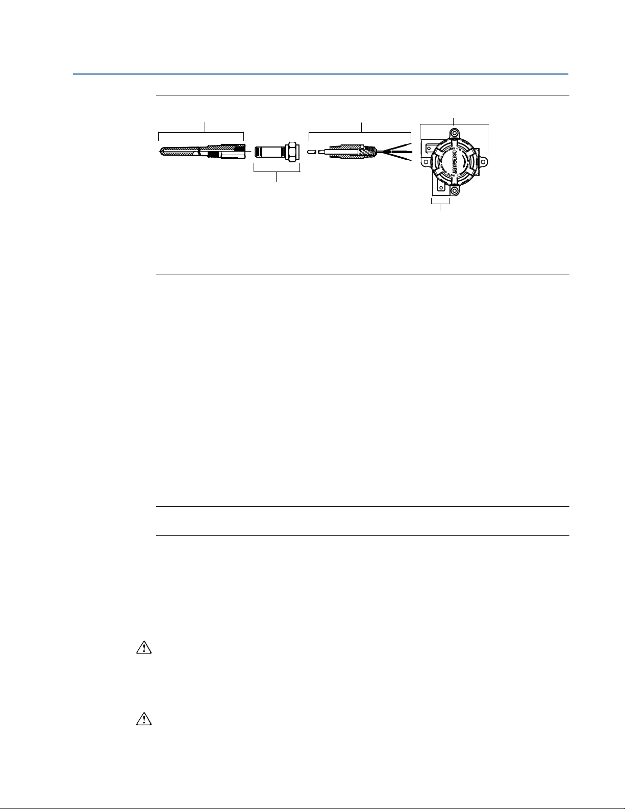
Examples of 148 Assemblies with Sensors and Thermowells
Tubular Thermowell and DIN Plate
Style Sensor
SEE SENSOR DOCUMENTATION FOR MORE ASSEMBLY OPTIONS
Dimensions are in millimeters (inches).
Barstock Thermowell, Nipple-Union
Barstock Thermowell and DIN Plate
Extension, and
Style Sensor
* 80 (3.2) for Class 900 flanges and larger
N = Extension Length, U= Thermowell Immersion Length,
1
/2-in. NPT Spring Loaded
Sensor
Specifications
33
Page 40

Appendix A: Specifications and reference data
April 2014
Reference Manual
00809-0100-4148, Rev CA
A.3 Ordering information
Table A-3. Rosemount 148 PC-Programmable Temperature Transmitter
★ The Standard offering represents the most common options. The starred options (★) should be selected for best delivery.
__The Expanded offering is subject to additional delivery lead time.
Model Product description
148 PC Programmable Temperature Transmitter
Transmitter type
Standard Standard
H DIN B Head Mount ★
Transmitter output
Standard Standard
N Analog Output ★
Product certifications
Standard Standard
I5 FM Intrinsic Safety and Class 1, Division 2 ★
(1)
E5
FM Explosion-Proof ★
(1)
K5
FM Intrinsic Safety, Explosion-Proof, and Class 1, Division 2 ★
I6 CSA Intrinsic Safety and Class 1, Division 2 ★
(1)
K6
CSA Intrinsic Safety, Explosion-Proof, and Class 1, Division 2 ★
I1 ATEX Intrinsic Safety ★
(1)
E1
ATE X Fl ameproof ★
(1)
N1
ATEX Type n ★
NC ATEX Type n Component ★
(1)
ND
E7
N7
NG IECEx Type n Component ★
NA No approvals ★
Enclosure options Material IP Rating
Standard Standard
Expanded
Conduit entry size
Standard Standard
ATEX Dust Ignition-Proof ★
I7 IECEx Intrinsic Safety ★
(1)
IECEx Flameproof and Dust ★
(1)
IECEx Type n ★
A Connection Head Aluminum IP68 ★
U Universal Head (Junction Box) Aluminum IP68 ★
B BUZ Head Aluminum IP65 ★
C BUZ Head Polypropylene IP65 ★
N No Enclosure ★
G Connection Head SST IP68
H Universal Head (Junction Box) SST IP68
S Sanitary Connection Head, DIN B Polished SST IP66
F Sanitary Connection Head, DIN A Polished SST IP66/IP68
1 M20 x 1.5 (CM20) ★
1
2
/2-14 in. NPT ★
0 No Enclosure ★
34
Specifications
Page 41

Reference Manual
00809-0100-4148, Rev CA
Appendix A: Specifications and reference data
April 2014
Table A-3. Rosemount 148 PC-Programmable Temperature Transmitter
★ The Standard offering represents the most common options. The starred options (★) should be selected for best delivery.
__The Expanded offering is subject to additional delivery lead time.
Options (include with selected model number)
Alarm level configuration
Standard Standard
A1 NAMUR alarm and saturation levels, high alarm ★
CN NAMUR alarm and saturation levels, low alarm ★
Calibration certificate
Standard Standard
Q4 Calibration Certificate (3-point Calibration) ★
Line filter
Standard Standard
F6 60 Hz Line Voltage Filter ★
External ground option (available w/enclosures U, H)
Standard Standard
G1 External Ground Lug Assembly ★
Cover chain option (available w/enclosures U, H)
Standard Standard
G3 Cover Chain ★
Cable gland option
Standard Standard
G2 Cable Gland–Explosion Proof–7.5 mm - 11.9 mm ★
G4 Cable Gland–Explosion Proof, Thin Wire - 3.0 mm - 8.0 mm ★
Conduit electrical connector
Standard Standard
GE M12, 4-pin, Male Connector (eurofast®) ★
GM A size Mini, 4-pin, Male Connector (minifast®) ★
Assemble to options
Standard Standard
XA Sensor Specified Separately and Assembled to Transmitter ★
Typical model number: 148 H N I5 U1 A1 XA
(1) Approval Codes E1, N1, N7, ND, E5, K5, K6, and E7 require an enclosure.
Specifications
35
Page 42

Appendix A: Specifications and reference data
April 2014
Reference Manual
00809-0100-4148, Rev CA
36
Specifications
Page 43

Reference Manual
00809-0100-4148, Rev BC
Appendix B: Product Certifications
April 2014
Appendix B Product Certifications
B.1 Approved Manufacturing Locations
Rosemount Inc. - Chanhassen, Minnesota, USA
Rosemount Temperature GmbH - Germany
Emerson Process Management Asia Pacific - Singapore
B.2 European Directive Information
A copy of the EC Declaration of Conformity can be found at the end of the Quick Start Guide. The
most recent revision of the EC Declaration of Conformity can be found at www.rosemount.com.
B.3 Ordinary Location Certification from FM Approvals
As standard, the transmitter has been examined and tested to determine that the design meets
the basic electrical, mechanical, and fire protection requirements by FM Approvals, a nationally
recognized test laboratory (NRTL) as accredited by the Federal Occupational Safety and Health
Administration (OSHA).
B.3.1 North America
E5 FM Explosionproof, Dust-Ignitionproof, and Nonincendive
Certificate: 3032198
Standards Used: FM Class 3600:1998, FM Class 3611:2004, FM Class 3615:1989, FM Class
3810:2005, IEC 60529: 2001, NEMA - 250: 1991
Markings: XP CL I, DIV 1, GP B, C, D; DIP CL II/III, DIV 1, GP E, F, G; NI CL I, DIV 2, GP A, B, C, D;
T5(-50 °C Ta + 85 °C); when installed per Rosemount drawing 00148-1065; Type 4X;
IP66/68.
I5 FM Intrinsic Safety and Nonincendive
Certificate: 3032198
Standards Used: FM Class 3600:1998, FM Class 3610:1999, FM Class 3611:2004, FM Class
3810:2005, IEC 60529: 2001, NEMA - 250: 1991
Markings: IS CL I/II/III, DIV 1, GP A, B, C, D, E, F, G; NI CL1, DIV 2, GP A, B, C, D; T6(-50 °C Ta
+ 40 °C), T5(-50 °C Ta + 75 °C) when installed per Rosemount drawing 00148-1055;
Type 4X; IP66/68.
Special conditions for safe use (X):
1. When no enclosure option is selected, the Model 148 Temperature Transmitter shall be
installed in an enclosure meeting the requirements of ANSI/ISA S82.01 and S82.03 or
other applicable ordinary location standards.
2. No enclosure or Buz Head option cannot be selected to maintain a Type 4X rating.
3. Enclosure option must be selected to maintain a Type 4 Rating.
Product Certifications
37
Page 44

Appendix B: Product Certifications
April 2014
I6 CSA Intrinsic Safety, and Division 2
Certificate: 1091070
Standards Used: CAN/CSA C22.2 No. 0-M90, CSA Std. C22.2 No. 25-1966, CSA Std. C22.2
No. 30-M1986, CAN/CSA C22.2 No. 94-M91, CSA Std. C22.2 No.142-M1987, CAN/CSA
C22.2 No. 157-92, CSA C22.2 No. 213-M1987, C22.2 No 60529-05.
Markings: IS CL I, DIV 1 GP A, B, C, D when installed per Rosemount drawing 00248-1056;
Suitable for CL I DIV 2 GP A, B, C, D when installed per Rosemount drawing 00248-1055;
T6(-50 °C Ta +40 °C), T5(-50 °C Ta +60 °C); Type 4X, IP66/68 for enclosure options “A”,
“G”, “H”, “U”; Seal not required (See drawing 00248-1066).
K6 CSA Explosionproof, Intrinsic Safety, and Division 2
Certificate: 1091070
Standards Used: CAN/CSA C22.2 No. 0-M90, CSA Std. C22.2 No. 25-1966, CSA Std. C22.2
No. 30-M1986, CAN/CSA C22.2 No. 94-M91, CSA Std. C22.2 No.142-M1987, CAN/CSA
C22.2 No. 157-92, CSA C22.2 No. 213-M1987, C22.2 No 60529-05.
Markings: XP CL I/II/III, DIV 1, GP B, C, D, E, F, G when installed per Rosemount drawing
00248-1066; IS CL I, DIV 1 GP A, B, C, D when installed per Rosemount drawing
00248-1056; Suitable for CL I DIV 2 GP A, B, C, D when installed per Rosemount drawing
00248-1055; T6(-50 °C Ta +40 °C), T5(-50 °C Ta +60 °C); Type 4X, IP66/68 for
enclosure options “A”, “G”, “H”, “U”; Seal not required (See drawing 00248-1066).
Reference Manual
00809-0100-4148, Rev BC
B.3.2 Europe
E1 ATE X Fla m eproof
Certificate: FM12ATEX0065X
Standards Used: EN 60079-0: 2012, EN 60079-1: 2007, EN 60529:1991 +A1:2000
Markings: II 2 G Ex d IIC T6…T1 Gb, T6(-50 °C Ta +40 °C), T5…T1(-50 °C Ta +60 °C);
See Ta bl e B - 1 at the end of the Product Certifications section for Process Temperatures
Special conditions for safe use (X):
1. See certificate for ambient temperature range.
2. The non-metallic label may store an electrostatic charge and become a source of ignition
in Group III environments.
3. Guard the LCD cover against impact energies greater than 4 joules.
4. Consult the manufacturer if dimensional information on the flameproof joints is
necessary.
I1 ATE X Intrinsic Safet y
Certificate: Baseefa08ATEX0030X
Standards Used: EN 60079-0: 2012, EN 60079-11: 2012
Markings: II 1 G Ex ia IIC T5/T6 Ga, T5(-60 °C Ta +80 °C), T6(-60 °C Ta +60 °C);
See Ta bl e B - 2 at the end of the Product Certifications section for Entity Parameters.
Special condition for safe use (X):
1. The apparatus must be installed in an enclosure which affords it a degree of protection of
at least IP20. Non-metallic enclosures must have a surface resistance of less than 1 G;
light alloy or zirconium enclosures must be protected from impact and friction when
installed.
38
N1 ATEX Type n - with enclosure
Certificate: BAS00ATEX3145
Standards Used: EN 60079-0:2012, EN 60079-15:2010
Markings: II 3 G Ex nA IIC T5 Gc (-40 °C Ta +70 °C);
Product Certifications
Page 45

Reference Manual
00809-0100-4148, Rev BC
NC ATEX Type n - without enclosure
1. The Model 148 Temperature Transmitter must be installed in a suitably certified
ND ATEX Dust
1. See certificate for ambient temperature range.
2. The non-metallic label may store an electrostatic charge and become a source of
3. Guard the LCD cover against impact energies greater than 4 joules.
4. Consult the manufacturer if dimensional information on the flameproof joints is
Appendix B: Product Certifications
April 2014
Certificate: Baseefa13ATEX0092X
Standards Used: EN 60079-0:2012, EN 60079-15:2010
Markings: II 3 G Ex nA IIC T5/T6 Gc, T5(-60 °C Ta +80 °C), T6(-60 °C Ta +60 °C);
Special condition for safe use (X):
enclosure such that it is afforded a degree of protection of at least IP54 in accordance
with IEC 60529 and EN 60079-15.
Certificate: FM12ATEX0065X
Standards Used: EN 60079-0: 2012, EN 60079-31: 2009, EN 60529:1991 +A1:2000
Markings: II 2 D Ex tb IIIC T130 °C Db, (-40 °C Ta +70 °C); IP66
See Table B -1 at the end of the Product Certifications section for Process Temperatures
Special conditions for safe use (X):
ignition in Group III environments.
necessary.
B.3.3 International
E7 IECEx Flameproof and Dust
Certificate: IECEx FMG 12.0022X
Standards Used: IEC 60079-0:2011, IEC 60079-1:2007-04, IEC 60079-31:2008
Markings: Ex d IIC T6…T1 Gb, T6(-50 °C Ta +40 °C), T5…T1(-50 °C Ta +60 °C);
Ex tb IIIC T130 °C Db, (-40 °C Ta +70 °C); IP66;
See Ta bl e B - 1 at the end of the Product Certifications section for Process Temperatures
Special conditions for safe use (X):
1. See certificate for ambient temperature range.
2. The non-metallic label may store an electrostatic charge and become a source of
ignition in Group III environments.
3. Guard the LCD cover against impact energies greater than 4 joules.
4. Consult the manufacturer if dimensional information on the flameproof joints is
necessary.
I7 IECEx Intrinsic Safety
Certificate: IECEx BAS 08.0011X
Standards Used: IEC 60079-0:2011, IEC 60079-11:2011
Markings: Ex ia IIC T5/T6 Ga, T5(-60 °C Ta +80 °C), T6(-60 °C Ta +60 °C);
See Ta bl e B - 2 at the end of the Product Certifications section for Entity Parameters
Special condition for safe use (X):
1. The apparatus must be installed in an enclosure which affords it a degree of protection
of at least IP20. Non-metallic enclosures must have a surface resistance of less than
1G; light allow or zirconium enclosures must be protected from impact and friction
when installed.
Product Certifications
39
Page 46

Appendix B: Product Certifications
April 2014
N7 IECEx Type n - with enclosure
Certificate: IECEx BAS 07.0055
Standards Used: IEC 60079-0:2011, IEC 60079-15:2010
Markings: Ex nA IIC T5 Gc; T5(-40 °C Ta +70 °C).
NG IECEx Type n - without enclosure
Certificate: IECEx BAS 13.0052X
Standards Used: IEC 60079-0:2011, IEC 60079-15:2010
Markings: Ex nA IIC T5/T6 Gc; T5(-60 °C Ta +80 °C), T6(-60 °C Ta +60 °C)
Special condition for safe use (X):
1. The Model 248 Temperature Transmitter must be installed in a suitably certified
enclosure such that it is afforded a degree of protection of at least IP54 in accordance
with IEC 60529 and IEC 60079-15.
B.3.4 Combinations
K5 Combination of E5 and I5
Reference Manual
00809-0100-4148, Rev BC
B.4 Tables
Table B-1. Process temperatures
Temperature class Ambient temperature
T6 -50 °C to +40 °C 55 55 60 65
T5 -50 °C to +60 °C 70 70 70 75
T4 -50 °C to +60 °C 100 110 120 130
T3 -50 °C to +60 °C 170 190 200 200
T2 -50 °C to +60 °C 280 300 300 300
T1 -50 °C to +60 °C 440 450 450 450
Tabl e B-2. Entity parameters
Voltage U
Current I
Power P
Capacitance C
Inductance L
Process temperature w/o LCD cover (°C)
No ext. 3” 6” 9”
HART loop terminals + and - Sensor terminals 1 to 4
i
i
i
i
i
30 V 45 V
130 mA 26 mA
1 W 290 mW
3.6 nF 2.1 nF
0 mH 0 μH
40
Product Certifications
Page 47

Reference Manual
148
00809-0100-4148, Rev BC
Appendix B: Product Certifications
Figure B-1. Installation drawing: 148 FM Intrinsic Safety, Drawing no. 00148-1055, Rev AA (1 of 2)
April 2014
Product Certifications
41
Page 48

Appendix B: Product Certifications
April 2014
Reference Manual
00809-0100-4148, Rev BC
Figure B-2. Installation drawing: 148 FM Intrinsic Safety, Drawing no. 00148-1055, Rev AA (2 of 2)
42
Product Certifications
Page 49

Reference Manual
00809-0100-4148, Rev BC
Appendix B: Product Certifications
April 2014
Figure B-3. Factory Mutual Explosion-Proof installation drawing, Drawing no. 00148-1065, Rev AA (1 of 1)
Product Certifications
43
Page 50

Appendix B: Product Certifications
April 2014
Reference Manual
00809-0100-4148, Rev BC
Figure B-4. CSA Explosion-Proof and Non-Incendive installation drawing, Drawing no. 00148-1056, Rev AA)
44
Product Certifications
Page 51

Reference Manual
00809-0100-4148, Rev BC
Appendix B: Product Certifications
Figure B-5. IECEX Intrinsic Safety installation drawing, Drawing no. 00148-1057, Rev AA
April 2014
Product Certifications
45
Page 52

Appendix B: Product Certifications
April 2014
Figure B-6. CSA Explosion-Proof installation drawing, Drawing no. 00644-1059, Rev AH
Reference Manual
00809-0100-4148, Rev BC
46
Product Certifications
Page 53

Page 54

Reference Manual
00809-0100-4148, Rev CA
April 2014
Standard Terms and Conditions of Sale can be found at www.rosemount.com/terms_of_sale
The Emerson logo is a trademark and service mark of Emerson Electric Co.
Rosemount. the Rosemount logotype, and SMART FAMILY are registered trademarks of Rosemount Inc.
Coplanar is a trademark of Rosemount Inc.
Halocarbon is a trademark of the Halocarbon Products Corporation.o.
Fluorinert is a registered trademark of Minnesota Mining and Manufacturing Company Corporation
Syltherm 800 and D.C. 200 are registered trademarks of Dow Corning Corporation.
Neobee M-20 is a registered trademark of PVO International, Inc.
HART is a registered trademark of the HART Communication Foundation.
Foundation fieldbus is a registered trademark of the Fieldbus Foundation.
All other marks are the property of their respective owners.
© April 2014 Rosemount, Inc. All rights reserved.
Emerson Process Management
Rosemount Measurement
8200 Market Boulevard
Chanhassen MN 55317 USA
Tel (USA) 1 800 999 9307
Tel (International) +1 952 906 8888
Fax +1 952 906 8889
Emerson Process Management
Latin America
1300 Concord Terrace, Suite 400
Sunrise Florida 33323 USA
Tel + 1 954 846 5030
Emerson Process Management
GmbH & Co.
Argelsrieder Feld 3
82234 Wessling
Germany
Tel 49 (8153) 9390
Fax 49 (8153) 939172
Emerson Process Management Asia
Pacific Private Limited
1 Pandan Crescent
Singapore 128461
T (65) 6777 8211
F (65) 6777 0947
Enquiries@AP.EmersonProcess.com
Beijing Rosemount Far East
Instrument Co., Limited
No. 6 North Street,
Hepingli, Dong Cheng District
Beijing 100013, China
T (86) (10) 6428 2233
F (86) (10) 6422 8586
 Loading...