

Page 1

Product Data Sheet
00813-0100-4016, Rev RF
Rosemount™ DP Level Transmitters and
1199 Diaphragm Seal Systems
December 2017
Applications
Level, flow, pressure, interface, density
Extreme hot and cold temperatures
Corrosive, clogging, or viscous processes
Hygienic requirements
Special process connections
Page 2

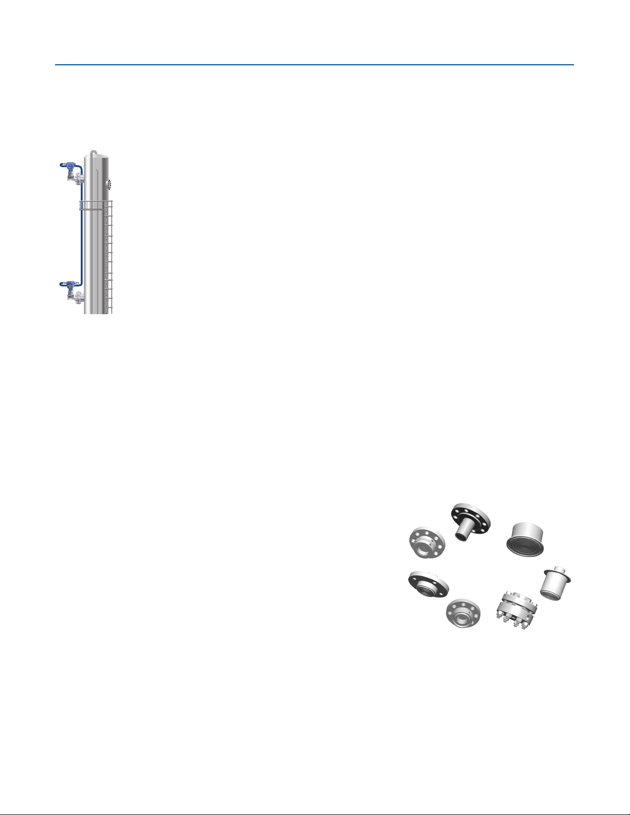
Rosemount DP Level
Direct mount
plus capillary
Two equ al l eng ths
of capillary
Balanced system Tuned-system assembly
December 2017
Proven, reliable, and innovative DP level technologies
To meet your application requirements, Rosemount DP Level technologies deliver an unsurpassed product offering that is easy to
specify, order, and install. The offering includes a wide variety of process connections, direct mount or capillary connections, and
materials of construction to address almost any application. If you don’t see what you need listed here, ask us. We can create a
custom engineered solution to meet your needs.
Rosemount Level Transmitters
Level transmitters combine world-class Rosemount pressure instrumentation with direct-mount seals, all in a single integrated
model number.
Rosemount 3051SAL, 3051L, and 2051L Level Transmitters
Achieve best-in-class system reliability with all welded systems
Wireless configurations provide new data access
Connect to virtually any process with a comprehensive offering of process
connections, fill fluids, direct mount or capillary connections, and
materials
Quantify and optimize total system performance with QZ option
Contents
Rosemount 3051S ERS System . . . . . . . . . . . . . . . . . . . . . . . . . . . 5
Rosemount 3051S Scalable™ Level Transmitter . . . . . . . . . . . . 22
Rosemount 3051L Level Transmitter . . . . . . . . . . . . . . . . . . . . . 54
Rosemount 2051L Liquid Level Transmitter . . . . . . . . . . . . . . . 62
Rosemount 1199 Direct Mount Seal Systems . . . . . . . . . . . . . 69
Rosemount 1199 Remote Mount Seal Systems . . . . . . . . . . . . 75
Flanged seals . . . . . . . . . . . . . . . . . . . . . . . . . . . . . . . . . . . . . . . . . 82
Rosemount Tuned-System™ Assemblies optimize results
Reduce installed costs by 20 percent by eliminating excess capillary and
transmitter mounting hardware
Improve performance by up to 30 percent
Increase response time by up to 80 percent
Reduce risk with up-front quantified performance reports
Threaded seals . . . . . . . . . . . . . . . . . . . . . . . . . . . . . . . . . . . . . . . 103
Hygienic seals . . . . . . . . . . . . . . . . . . . . . . . . . . . . . . . . . . . . . . . .108
Specialty seals . . . . . . . . . . . . . . . . . . . . . . . . . . . . . . . . . . . . . . . .119
Specifications . . . . . . . . . . . . . . . . . . . . . . . . . . . . . . . . . . . . . . . .126
Product certifications . . . . . . . . . . . . . . . . . . . . . . . . . . . . . . . . .142
Dimensional drawings . . . . . . . . . . . . . . . . . . . . . . . . . . . . . . . . .169
2
Emerson.com/Rosemount
Page 3
December 2017
Rosemount DP Level
Rosemount 3051S Electronic Remote Sensor (ERS)™ System
The Rosemount 3051S ERS System is a digital DP Level architecture that links two Rosemount 3051S Pressure Sensors together
electronically. The pressure sensors are synchronized on a single power loop where the differential pressure, level, and volume are
calculated and transmitted using a standard two-wire 4–20mA HART® signal.
A digital upgrade to a proven technology
90 percent improvement in time response
Elimination of temperature effects and measurement drift
Multivariable capabilities including DP, P
Proven Rosemount 3051S Sensor technology
, PHI, volume, and level
LO
Simplified installations and maintenance routines
Elimination of wet legs or dry legs
Easy installations without need for heat tracing and insulation
Proactive maintenance and troubleshooting with sensor alerts and diagnostics
Simplified inventories with sensors and standard cable
Rosemount 1199 Seal Systems
A seal system consists of a pressure transmitter, one or two seals, a fill fluid, and either a direct mount or capillary style connection.
Seal systems provide a reliable process pressure measurement and prevent the process medium from contacting the transmitter
diaphragm. Transmitter/diaphragm seal systems should be considered when:
The process temperature is outside of the operating ranges of the transmitter.
The process is corrosive and/or requires specific exotic materials of construction.
The process contains suspended solids or is viscous and is prone to plugging of connections.
The application requires the use of flush-mount hygienic connections that facilitates CIP/SIP service.
There is a requirement for easier cleaning of the process from the connections to avoid contamination between batches.
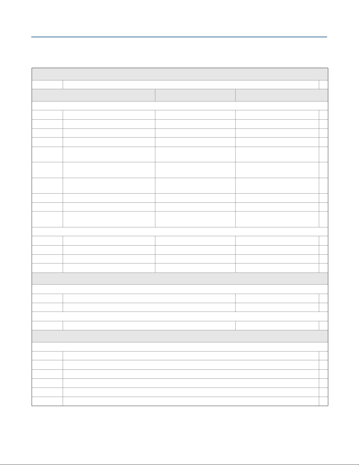
Application flexibility
Flanged, threaded, and hygienic process connections
Meets industry standards such as EN 1092-1, ANSI/ASME B16.5, JIS B2238,
ANSI/ASME B1.20.1, EN 10226-1, GOST 33259-15, ISO 228-1
Variety of fill fluids applications including cold temperature, hot temperature, and
hygienic and food grade
Three different capillary diameters allow for optimization of accuracy and time
response.
Reliable system construction
Welded design with no threaded connections
100 percent helium leak tested
Advanced manufacturing techniques ensure air-free, leak-tight system that is stable over time
Reliable operation in full vacuum applications
Robust seal design
Backup convolutions on the diaphragm protect seal integrity.
Recessed diaphragms reduce potential for handling damage.
Emerson.com/Rosemount
3
Page 4

Rosemount DP Level
Figure 1. Rosemount Seal System Construction Options
Welded-repairable construction All welded (vacuum) construction
December 2017
All connection pointed welded except gasket between sensor
module and transmitter flange
Transmitter can be re-used if repair work is required Ideal for vacuum applications (< 6 psia, 400 mbar-a)
All connection points welded including welded disk over sensor
module isolators
Seal system and transmitter are not repairable
4
Emerson.com/Rosemount
Page 5

December 2017
Rosemount 3051SAL
1
2
Primary
Coplanar
In-Line
Coplanar
In-Line
3051SAL1PG4AA1A1020DFF71DA00M5
3051SAM1ST2A2E11A2A
3
Rosemount 3051SAM
Secondary
Rosemount 3051S ERS System
The Rosemount 3051S ERS System is a flexible, 2-wire 4–20 mA HART
architecture that calculates differential pressure (DP) electronically using two
pressure sensors that are linked together with a non-proprietary electrical wire.
Ideal applications for the Rosemount 3051S ERS System include tall vessels and
distillation columns that have traditionally required long lengths of capillary or
impulse piping. When used in these types of applications, the Rosemount
3051S ERS System can deliver:
More accurate and repeatable DP measurements
Faster time response
Simplified installations
Reduced maintenance
How to order
1. Select two Rosemount 3051S ERS Transmitter models. These may be any
combination of Rosemount 3051SAM and 3051SAL models.
2. Decide which model will be the ERS primary (4–20 mA loop termination and
optional LCD display) and which will be the ERS Secondary. This will be
specified by the “Configuration Type” code in each model number.
3. Specify two full model numbers per the desired configuration.
Additional information
Specifications: page 126
Certifications: page 142
Dimensional drawings: page 169
Rosemount DP Level
Specification and selection of product materials, options, or components must be made by the purchaser of the equipment.
See
Table 1. Rosemount 3051SAM Transmitter for ERS Applications Ordering Information
The starred offerings (★) represent the most common options and should be selected for best delivery. The non-starred offerings are subject
to additional delivery lead time.
Rosemount
model
3051SAM Scalable advanced measurement transmitter
Performance class
1 Ultra: 0.025% span accuracy, 200:1 rangedown, 15-year stability, 15-year limited warranty ★
2 Classic: 0.035% span accuracy, 150:1 rangedown, 15-year stability ★
4 Enhanced ERS System performance, 15-year stability, 15-year limited warranty ★
Configuration type
P ERS - primary ★
S ERS - secondary ★
Rosemount 3051SAM Transmitter for ERS applications
Coplanar and in-line sensor module platforms
Variety of process connections including threaded NPT, flanges, manifolds, and Rosemount 1199 Remote
seals
Available with 15-year stability and 15-year limited warranty
page 136 for more information on material selection.
Transmitter type
(1)
Emerson.com/Rosemount
5
Page 6

Rosemount DP Level
December 2017
Table 1. Rosemount 3051SAM Transmitter for ERS Applications Ordering Information
The starred offerings (★) represent the most common options and should be selected for best delivery. The non-starred offerings are subject
to additional delivery lead time.
Pressure module type Pressure sensor type
G Coplanar Gage ★
T In-Line Gage ★
E In-Line Absolute ★
A Coplanar Absolute
Pressure range
1A N/A
2A
(2)
Coplanar gage In-Line gage In-Line absolute Coplanar absolute
–250 to 250 inH2O
(–621,60 to 621,60 mbar)
–14.7 to 30 psig
(–1,01 to 2,06 bar)
–14.7 to 150 psig
(–1,01 to 10,34 bar)
0 to 30 psia
(0 to 2,06 bar)
0 to 150 psia
(0 to 10,34 bar)
0 to 30 psia
(0 to 2,06 bar)
0 to 150 psia
(0 to 10,34 bar)
★
★
3A
4A
5A
–393 to 1000 inH2O
(–0,97 to 2,48 bar)
–14.2 to 300 psig
(–0,97 to 20,68 bar)
–14.2 to 2000 psig
(–0,97 to 137,89 bar)
–14.7 to 800 psig
(–1,01 to 55,15 bar)
–14.7 to 4000 psig
(–1,01 to 275,79 bar)
–14.7 to 10000 psig
(–1,01 to 689,47 bar)
Isolating diaphragm
(3)
2
3
4
5
6
7
(3)
(3)(4)
(4)(5)
(3)(4)
(3)(4)
316L SST
Alloy C-276
Alloy 400
Ta nt a l u m
Gold-plated alloy 400 (includes graphite-filled PTFE O-ring)
Gold-plated 316L SST
Process connection
Coplanar module type In-Line module type
(6)
A11
(6)
A12
(6)
A15
(6)
A22
(6)(7)
B11
E11 Coplanar flange (CS), 1/4–18 NPT, 316 SST drain vents
Assemble to Rosemount 305 Manifold Assemble to Rosemount 306 Manifold ★
Assemble to Rosemount 304 or AMF Manifold with SST
traditional flange
Assemble to Rosemount 304 or AMF manifold to SST
traditional flange with alloy C-276 drain vents
Assemble AMF manifold to SST coplanar flange N/A ★
Assemble to one Rosemount 1199 Remote Diaphragm
Seal with SST transmitter flange
0 to 800 psia
(0 to 55,15 bar)
0 to 4000 psia
(0 to 275,79 bar)
0 to 10000 psia
(0 to 689,47 bar)
0 to 800 psia
(0 to 55,15 bar)
0 to 4000 psia
(0 to 275,79 bar)
N/A ★
Assemble AMF Manifold to 1/2–14 NPT female
process connection
N/A ★
Assemble to one Rosemount 1199 Remote
Diaphragm
1
/2–14 NPT female process connection ★
★
★
★
★
★
★
6
Emerson.com/Rosemount
Page 7

December 2017
Rosemount DP Level
Table 1. Rosemount 3051SAM Transmitter for ERS Applications Ordering Information
The starred offerings (★) represent the most common options and should be selected for best delivery. The non-starred offerings are subject
to additional delivery lead time.
Process connection
Coplanar module type In-Line module type
E12 Coplanar flange (SST), 1/4–18 NPT, 316 SST drain vents N/A ★
E13
(3)
Coplanar flange (cast C-276), 1/4–18 NPT, alloy C-276 drain
vents
N/A ★
E14
E15
E16
(3)
(3)
Coplanar flange (cast alloy 400), 1/4–18 NPT, alloy 400/
K–500 drain vents
N/A ★
Coplanar flange (SST), 1/4–18 NPT, Alloy C-276 drain vents N/A ★
Coplanar flange (CS), 1/4–18 NPT, Alloy C-276 drain vents N/A ★
E21 Coplanar flange (CS), RC 1/4, 316 SST drain vents N/A ★
E22 Coplanar flange (SST), RC 1/4, 316 SST drain vents N/A ★
E23
E24
E25
E26
(3)
(3)
(3)
Coplanar flange (Cast C-276), RC 1/4, alloy C-276 drain
vents
Coplanar flange (cast alloy 400), RC 1/4, alloy 400/K–500
drain vents
N/A ★
N/A ★
Coplanar flange (SST), RC 1/4, alloy C-276 drain vents N/A ★
Coplanar flange (CS), RC 1/4, alloy C-276 drain vents N/A ★
F12 Traditional flange (SST), 1/4–18 NPT, 316 SST drain vents N/A ★
F13
F14
F15
(3)
(3)
Traditional flange (cast C-276), 1/4–18 NPT, alloy C-276
drain vents
Traditional flange (cast alloy 400), 1/4–18 NPT, alloy 400/
K–500 drain vents
Traditional flange (SST), 1/4–18 NPT, alloy C-276 drain
vents
N/A ★
N/A ★
N/A ★
F22 Traditional flange (SST), RC 1/4, 316 SST drain vents N/A ★
F23
F24
F25
F52
(3)
(3)
Traditional flange (cast C-276), RC 1/4, alloy C-276 drain
vents
Traditional flange (cast alloy 400), RC 1/4, alloy 400/K500
drain vents
N/A ★
N/A ★
Traditional flange (SST), RC 1/4, alloy C-276 drain vents N/A ★
DIN-compliant traditional flange (SST), 1/4–18 NPT, 316
7
drain vents,
/16-in. bolting
N/A ★
G11
G12
G21
G22
Vertical mount level flange (SST), 2-in. ANSI Class 150, 316
SST drain vents
Vertical mount level flange (SST), 2-in. ANSI Class 300, 316
SST drain vents
Vertical mount level flange (SST), 3-in. ANSI Class 150, 316
SST drain vents
Vertical mount level flange (SST), 3-in. ANSI Class 300, 316
SST drain vents
Emerson.com/Rosemount
G1/2 A DIN 16288 male (range 1–4 only) ★
N/A ★
N/A ★
N/A ★
7
Page 8

Rosemount DP Level
December 2017
Table 1. Rosemount 3051SAM Transmitter for ERS Applications Ordering Information
The starred offerings (★) represent the most common options and should be selected for best delivery. The non-starred offerings are subject
to additional delivery lead time.
Process connection
Coplanar module type In-line module type
G31
G41
Vertical mount level flange (SST), DIN-DN 50 PN 40, 316
SST drain vents
Vertical mount level flange (SST), DIN-DN 80 PN 40, 316
SST drain vents
N/A ★
N/A ★
P11 N/A Level flange (SST), 2-in. ANSI Class 150 ★
P12 N/A Level flange (SST), 2-in. ANSI Class 300 ★
P21 N/A Level flange (SST), 3-in. ANSI Class 150 ★
P22 N/A Level flange (SST), 3-in. ANSI Class 300 ★
P31 N/A Level flange (SST), DIN-DN 50 PN 40 ★
F11 Traditional flange (CS), 1/4–18 NPT, 316 SST drain vents Non-threaded instrument flange (I-Flange)
F32
F42
F62
F72
Bottom vent traditional flange (SST), 1/4–18 NPT, 316 SST
drain vents
Bottom vent traditional flange (SST), RC 1/4, 316 SST drain
vents
DIN-compliant traditional flange (316 SST), 1/4–18 NPT,
316 drain vents, M10 bolting
DIN-compliant traditional flange (316 SST), 1/4–18 NPT,
316 drain vents, M12 bolting
N/A
N/A
N/A
N/A
Transmitter output
A 4–20 mA with digital signal based on HART Protocol ★
Housing style Material Conduit entry size
Housings for ERS primary - configuration type code P
1A Plantweb™ housing Aluminum
1B Plantweb housing Aluminum M20 ⫻ 1.5 (CM 20) ★
1J Plantweb housing SST
1K Plantweb housing SST M20 ⫻1.5 (CM 20) ★
2E Junction box with remote display output Aluminum
2F Junction box with remote display output Aluminum M20 ⫻ 1.5 (CM 20) ★
2M Junction box with remote display output SST
1C Plantweb housing Aluminum G1/2
1L Plantweb housing SST G1/2
2G Junction box with remote display output Aluminum G1/2
Housings for ERS secondary - configuration type code S
2A Junction box Aluminum
2B Junction box Aluminum M20 ⫻ 1.5 (CM 20) ★
1
/2–14 NPT ★
1
/2–14 NPT ★
1
/2–14 NPT ★
1
/2–14 NPT ★
1
/2–14 NPT ★
8
Emerson.com/Rosemount
Page 9

December 2017
Rosemount DP Level
Table 1. Rosemount 3051SAM Transmitter for ERS Applications Ordering Information
The starred offerings (★) represent the most common options and should be selected for best delivery. The non-starred offerings are subject
to additional delivery lead time.
2J Junction box SST
1
/2–14 NPT ★
2C Junction box Aluminum G1/2
Options (include with selected model number)
Extended product warranty
WR3 3-year limited warranty ★
WR5 5-year limited warranty
ERS connection cable
R02 25 ft. (7,62 m) spool of ERS cable (gray color)
R05 50 ft. (15,2 m) spool of ERS cable (gray color) ★
R10 100 ft. (30,5 m) spool of ERS cable (gray color) ★
R15 150 ft. (45,7 m) spool of ERS cable (gray color) ★
(8)
R20
(9)
R22
R30 300 ft. (91,44 m) spool of ERS cable (gray color)
R40 400 ft. (121,9 m) spool of ERS cable (gray color)
R50 500 ft. (152,4 m) spool of ERS cable (gray color)
H02 25 ft. (7,62 m) spool of ERS cable (blue color)
H05 50 ft. (15,2 m) spool of ERS cable (blue color)
H10 100 ft. (30,5 m) spool of ERS cable (blue color)
H15 150 ft. (45,7 m) spool of ERS cable (blue color)
(8)
H20
(9)
H22
200 ft. (60,96 m) spool of ERS cable (gray color)
225 ft. (68,58 m) spool of ERS cable (gray color)
200 ft. (60,96 m) spool of ERS cable (blue color)
225 ft. (68,58 m) spool of ERS cable (blue color)
★
J02 25 ft. (7,62 m) spool of ERS armored cable with 1/2 in. armor cable gland
J05 50 ft. (15,2 m) spool of ERS armored cable with 1/2 in. armor cable gland
J07 75 ft. (22,8 m) spool of ERS armored cable with 1/2 in. armor cable gland
J10 100 ft. (30,5 m) spool of ERS armored cable with 1/2 in. armor cable gland
(9)
J12
125 ft. (38,1 m) spool of ERS armored cable with 1/2 in. armor cable gland
Mounting bracket
(4)
B1
B2
B3
(4)
(4)
Traditional flange bracket, CS, 2-in. pipe ★
Traditional flange bracket, CS, panel ★
Traditional flange flat bracket, CS, 2-in. pipe ★
B4 Bracket, all SST, 2-in. pipe and panel ★
(4)
B7
B8
B9
(4)
(4)
Traditional flange bracket, B1 with SST bolts ★
Traditional flange bracket, B2 with SST bolts ★
Traditional flange bracket, B3 with SST bolts ★
Emerson.com/Rosemount
9
Page 10

Rosemount DP Level
December 2017
Table 1. Rosemount 3051SAM Transmitter for ERS Applications Ordering Information
The starred offerings (★) represent the most common options and should be selected for best delivery. The non-starred offerings are subject
to additional delivery lead time.
(4)
BA
BC
(4)
Traditional flange bracket, B1, all SST ★
Traditional flange bracket, B3, all SST ★
Special configuration (software)
(10)
C1
Customer software configuration (requires Configuration Data Sheet) ★
C3 Gage pressure calibration on Rosemount 3051SAM_ _A4 only ★
(10)
C4
C5
C6
C7
C8
(10)
(10)
(10)
(10)
NAMUR alarm and saturation levels, high alarm ★
NAMUR alarm and saturation levels, low alarm ★
Custom alarm and saturation levels, high alarm (requires C1 and Configuration Data Sheet) ★
Custom alarm and saturation levels, low alarm (requires C1 and Configuration Data Sheet) ★
Low alarm (standard Rosemount alarm and saturation levels) ★
Special configuration (hardware)
D2
D4
D5
D7
D9
(11)
(12)
(11)
(11)
(11)
1
/2–14 NPT flange adapters ★
External ground screw assembly ★
Delete transmitter drain/vent valves (install plugs) ★
Coplanar flange without drain/vent ports
RC 1/2 flange adapters
Product certifications
E1 ATEX Fla mep roof ★
I1 ATEX Intrinsic Safety ★
N1 ATEX Type n ★
K1 ATEX Flameproof and Intrinsically Safe, Type n, Dust ★
ND ATEX Dust ★
E4 TIIS Flameproof ★
E5 FM Explosion-proof, Dust Ignition-proof ★
I5 FM Intrinsically Safe; Nonincendive ★
K5 FM Explosion-proof, Dust Ignition-proof, Intrinsically Safe, Division 2 ★
(13)
E6
I6 CSA Intrinsically Safe ★
(13)
K6
E7 IECEx Flameproof ★
I7 IECEx Intrinsic Safety ★
N7 IECEx Type n ★
K7 IECEx Flameproof, Intrinsic Safety, Type n ★
CSA Explosion-proof, Dust Ignition-proof, Division 2 ★
CSA Explosion-proof, Dust Ignition-proof, Intrinsically Safe, Division 2 ★
E2 INMETRO Flameproof ★
I2 INMETRO Intrinsically Safe ★
K2 INMETRO Flameproof, Intrinsic Safety, Type n ★
10
Emerson.com/Rosemount
Page 11

December 2017
Rosemount DP Level
Table 1. Rosemount 3051SAM Transmitter for ERS Applications Ordering Information
The starred offerings (★) represent the most common options and should be selected for best delivery. The non-starred offerings are subject
to additional delivery lead time.
E3 China Flameproof ★
I3 China Intrinsic Safety, Dust Ignition-proof ★
EP Korea Flameproof ★
IP Korea Intrinsic Safety ★
KP Korea Flameproof, Intrinsic Safety ★
EM Technical Regulations Customs Union (EAC) Flameproof ★
IM Technical Regulations Customs Union (EAC) Intrinsic Safety ★
KM Technical Regulations Customs Union (EAC) Flameproof, Intrinsic Safety ★
(13)
KA
KB
(13)
ATEX and CSA Flameproof, Intrinsically Safe, Division 2 ★
FM and CSA Explosion-proof, Dust Ignition-proof, Intrinsically Safe, Division 2 ★
KC FM and ATEX Explosion-proof, Intrinsically Safe, Division 2 ★
(13)
KD
FM, CSA, and ATEX Explosion-proof, Intrinsically Safe ★
Shipboard approvals
SBS American Bureau of Shipping (ABS) Type Approval ★
SBV Bureau Veritas (BV) Type Approval ★
SDN Det Norske Veritas (DNV) Type Approval ★
SLL Lloyds Register (LR) Type Approval ★
Calibration certification
Q4 Calibration certificate ★
QP Calibration certificate and tamper evident seal ★
Material traceability certification
Q8 Material traceability certification per EN 10204 3.1 ★
Quality certification for safety
QS Prior-use certificate of FMEDA Data ★
QT Safety certified to IEC 61508 with certificate of FMEDA data ★
Surface finish certification
Q16 Surface finish certification for hygienic remote seals ★
Toolkit performance reports
QZ Remote seal system performance calculation report ★
Terminal blocks
(10)
(14)
(15)
T1 Transient terminal block ★
Sensor fill fluid
(16)
L1 Inert sensor fill fluid ★
Emerson.com/Rosemount
11
Page 12

Rosemount DP Level
December 2017
Table 1. Rosemount 3051SAM Transmitter for ERS Applications Ordering Information
The starred offerings (★) represent the most common options and should be selected for best delivery. The non-starred offerings are subject
to additional delivery lead time.
O-ring
L2 Graphite-filled PTFE O-ring ★
Bolting material
L4 Austenitic 316 SST bolts ★
(3)
L5
L6 Alloy K–500 bolts ★
(3)
L7
L8 ASTM A 193, Class 2, grade B8M bolts ★
Display type (ERS primary only)
M5 Plantweb LCD display ★
(17)
M7
M8 Remote mount LCD display and interface, Plantweb housing, 50 ft. (15,2 m) cable, SST bracket ★
M9 Remote mount LCD display and interface, Plantweb housing, 100 ft. (30,5 m) cable, SST bracket ★
(11)
ASTM A 193, grade B7M bolts ★
ASTM A 453, Class D, grade 660 bolts ★
(10)
Remote mount LCD display and interface, Plantweb housing, no cable, SST bracket ★
Pressure testing
P1 Hydrostatic testing with certificate
Special cleaning
(11)
P2 Cleaning for special services
P3 Cleaning for less than 1 PPM chlorine/fluorine
NACE certificate
(3)
Q15 Certificate of compliance to NACE® MR0175/ISO 15156 for wetted materials ★
Q25 Certificate of compliance to NACE MR0103 for wetted materials ★
Typical model number: 3051SAM 1 S T 2A 2 E11 A 2A
1. For detailed specifications see “Specifications” on page 126. The Rosemount 3051S ERS System offers three performance class options; classic, ultra, and enhanced
ERS system performance. The classic and ultra performance classes are suited to lower static pressure and stable temperature conditions. The enhanced ERS system
performance class provides better performance across temperature (–40 to 185 °F) with improved performance at higher static pressure.
2. The pressure range should be specified based on the maximum static pressure, not differential pressure.
3. Materials of construction comply with metallurgical requirements highlighted within NACE MR 0175/ISO 15156 for sour oil field production environments.
Environmental limits apply to certain materials. Consult latest stan dard for d eta ils . Sel ect ed ma teri als also conf orm to NA CE M R 0103 for sour refining environments.
Order with Q15 or Q25 to receive a NACE certificate.
4. Not available with pressure sensor/module codes T or E.
5. Tantalum diaphragm material is only available with pressure sensor/module code G.
6. “Assemble to” items are specified separately and require a completed model number.
7. Consult an Emerson
8. Maximum cable distance for SIS installations. See Rosemount 3051S ERS Reference Manual
9. Maximum cable distance for IS (Intrinsically safe) installations. Other options may not be valid at longer distances.
10. Not available with configuration type cod e S.
11. Not available with process connection code A11.
12. This assembly is included with options E1, N1, K1, ND, E4, E7, N7, K7, E2, KA, KC, KD, K2, T1, EP, and KP.
13. Not available with M20 or G
™
representative for performance specifications.
1
/2 conduit entry size.
for more information.
12
Emerson.com/Rosemount
Page 13

December 2017
14. Q16 is only available when the diaphragm seal has surface finish options.
15. The QZ report quantifies the performance of the entire ERS system. One report is provided per ERS system. The QZ option is specified on the primary transmitter
(configuration type code P).
16. Silicone fill fluid is standard.
17. See the Rosemount 3051S Reference Manual
for cable requirements. Contac t an Emerson representative for additional information.
Rosemount DP Level
Emerson.com/Rosemount
13
Page 14

Rosemount DP Level
ERS transmitter model codes__page 14 Direct mount seal model codes_page 69 ERS options____page 18
December 2017
Rosemount 3051SAL Transmitter for ERS applications
Integrated transmitter and direct mount diaphragm seal system in a single model number
Variety of process connections including flanged, threaded, and hygienic remote seals
Available with 15-year limited warranty
Specification and selection of product materials, options, or components must be made by the purchaser of the equipment.
See page 136 for more information on material selection.
A Rosemount 3051SAL Scalable ERS Level Transmitter consists of three parts. First, specify the transmitter model codes found on
page 14. Then, specify a direct mount seal found on page 69. Finish the model number by specifying all desired options on page 18.
Table 2. Rosemount 3051SAL Transmitter for ERS Applications Ordering Information
The starred offerings (★) represent the most common options and should be selected for best delivery. The non-starred offerings are subject
to additional delivery lead time.
Rosemount
model
Transmitter type
3051SAL Scalable advanced level transmitter
Performance class
(1)
1 Ultra: 0.055% span accuracy, 150:1 rangedown, 15-year limited warranty ★
2 Classic: 0.065% span accuracy, 150:1 rangedown ★
4 Enhanced ERS System performance, 15-year limited warranty ★
Configuration type
P ERS - primary ★
S ERS - secondary ★
Pressure module type Pressure sensor type
G Coplanar Gage ★
T In-line Gage ★
E In-line Absolute ★
A Coplanar Absolute
Pressure range
1A N/A
2A
3A
4A
5A
(2)
Coplanar gage In-line gage In-line absolute
–250 to 250 inH2O
(–621.60 to 621.60
mbar)
–393 to 1000 inH2O
(–0.97 to 2.48 bar)
–14.2 to 300 psig
(–0.97 to 20.68 bar)
–14.2 to 2000 psig
(–0.97 to 137.89 bar)
–14.7 to 30 psig
(–1.01 to 2.06 bar)
–14.7 to 150 psig
(–1.01 to 10.34 bar)
–14.7 to 800 psig
(–1.01 to 55.15 bar)
–14.7 to 4000 psig
(–1.01 to 275.79 bar)
–14.7 to 10000 psig
(–1.01 to 689.47 bar)
0 to 30 psia
(0 to 2.06 bar)
0 to 150 psia
(0 to 10.34 bar)
0 to 800 psia
(0 to 55.15 bar)
0 to 4000 psia
(0 to 275.79 bar)
0 to 10000 psia
(0 to 689.47 bar)
Coplanar
absolute
0 to 30 psia
(0 to 2.06 bar)
0 to 150 psia
(0 to 10.34 bar)
0 to 800 psia
(0 to 55.15 bar)
0 to 4000 psia
(0 to 275.79 bar)
N/A ★
★
★
★
★
14
Emerson.com/Rosemount
Page 15
December 2017
Rosemount DP Level
Table 2. Rosemount 3051SAL Transmitter for ERS Applications Ordering Information
The starred offerings (★) represent the most common options and should be selected for best delivery. The non-starred offerings are subject
to additional delivery lead time.
Transmitter output
A 4–20 mA with digital signal based on HART Protocol ★
Housing style Material Conduit entry size
Housings for ERS primary - configuration type code P
1A Plantweb housing Aluminum
1B Plantweb housing Aluminum M20 ⫻ 1.5 (CM 20) ★
1J Plantweb housing SST
1K Plantweb housing SST M20 ⫻1.5 (CM 20) ★
2E
2F
2M
Junction box with remote display
output
Junction box with remote display
output
Junction box with remote display
output
Aluminum
Aluminum M20 ⫻1.5 (CM 20) ★
SST
1C Plantweb housing Aluminum G1/2
1L Plantweb housing SST G1/2
2G
Junction box with remote display
output
Aluminum G1/2
Housings for ERS secondary - configuration type code S
2A Junction box Aluminum
2B Junction box Aluminum M20 ⫻ 1.5 (CM 20) ★
2J Junction box SST
2C Junction box Aluminum G1/2
1
/2–14 NPT ★
1
/2–14 NPT ★
1
/2–14 NPT ★
1
/2–14 NPT ★
1
/2–14 NPT ★
1
/2–14 NPT ★
Seal system type
Coplanar pressure module type
1 Single direct mount seal system Welded-repairable ★
2 Single direct mount seal system All welded ★
In-line pressure module type
1 Single direct mount seal system All welded ★
High side connection type
Single direct mount seal system (between transmitter and remote seal)
0 No extension ★
2 2-in. (50 mm) extension ★
4 4-in. (100 mm) extension ★
(3)
5
6
7
(4)
(5)(4)
Thermal optimizer ★
Thermal range expander - Silicone 200 secondary fill fluid ★
Thermal range expander - Syltherm™ XLT secondary fill fluid ★
Emerson.com/Rosemount
15
Page 16

Rosemount DP Level
December 2017
Table 2. Rosemount 3051SAL Transmitter for ERS Applications Ordering Information
The starred offerings (★) represent the most common options and should be selected for best delivery. The non-starred offerings are subject
to additional delivery lead time.
Low side connection type (reference pressure connection)
Single direct mount seal system
00 None (In-line pressure module type only) ★
20 316L SST isolator/SST transmitter flange ★
30 Alloy C-276 isolator/SST transmitter flange ★
Temperature limits
(6)(7)
Specific
Seal fill fluid
gravity at
77 °F
(25 °C)
No extension
2-in.
(50 mm)
extension
4-in.
(100 mm)
extension
Thermal range
expander
(process
temperature)
(8)
D Silicone 200 0.934
F
(9)
J
(9)
Q
Silicone 200 for vacuum
applications
0.934
Tri-Therm 300 0.795
Tri-Therm 300 for
vacuum applications
0.795
L Silicone 704 1.07
C
Silicone 704 for vacuum
applications
1.07
R Silicone 705 1.09
V
Silicone 705 for vacuum
applications
1.09
A Syltherm XLT 0.85
H Inert (halocarbon) 1.85
(9)(10)
G
N
(9)(10)
P
(11)
Y
(11)
Z
(9)
Glycerin and water 1.13
Neobee® M-20 0.94
Propylene glycol and
water
1.02
UltraTherm™ 805 1.20 N/A N/A N/A
UltraTherm 805 for
vacuum applications
1.20
–49 to 401 °F
(–45 to 205 °C)
–49 to 401 °F
(–45 to 205 °C)
–49 to 401 °F
(–45 to 205 °C)
N/A ★
For use in vacuum applications below 14.7 psia (1 bar-a), refer to vapor
pressure curves in Rosemount DP Level Fill Fluid Specification
Technical Note
–40 to 401 °F
(–40 to 205 °C)
–40 to 464 °F
(–40 to 240 °C)
–40 to 572 °F
(–40 to 300 °C)
N/A ★
For use in vacuum applications below 14.7 psia (1 bar-a), refer to vapor
pressure curves in Rosemount DP Level Fill Fluid Specification
Technical Note
32 to 401 °F
(0 to 205 °C)
32 to 464 °F
(0 to 240 °C)
32 to 572 °F
(0 to 300 °C)
Up to 599 °F
(315 °C)
For use in vacuum applications below 14.7 psia (1 bar-a), refer to vapor
pressure curves in Rosemount DP Level Fill Fluid Specification
Technical Note
68 to 401 °F
(20 to 205 °C)
68 to 464 °F
(20 to 240 °C)
68 to 572 °F
(20 to 300 °C)
Up to 698 °F
(370 °C)
For use in vacuum applications below 14.7 psia (1 bar-a), refer to vapor
pressure curves in Rosemount DP Level Fill Fluid Specification
Technical Note
–157 to 293 °F
(–105 to 145
°C)
–49 to 320 °F
(–45 to 160 °C)
5 to 203 °F
(–15 to 95 °C)
5 to 401 °F
(–15 to 205 °C)
5 to 203 °F
(–15 to 95 °C)
–157 to 293 °F
(–105 to 145
°C)
–49 to 320 °F
(–45 to 160 °C)
5 to 203 °F
(–15 to 95 °C)
5 to 437 °F
(–15 to 225 °C)
5 to 203 °F
(–15 to 95 °C)
–157 to 293 °F
(–105 to 145
°C)
–49 to 320 °F
(–45 to 160 °C)
5 to 203 °F
(–15 to 95 °C)
5 to 437 °F
(–15 to 225 °C)
5 to 203 °F
(–15 to 95 °C)
N/A ★
N/A ★
N/A ★
N/A ★
N/A ★
Up to 770 °F
(410 °C)
For use in vacuum applications below 14.7 psia (1 bar-a), refer to vapor
pressure curves in Rosemount DP Level Fill Fluid Specification
Technical Note
★
★
★
★
★
★
★
★
16
Emerson.com/Rosemount
Page 17

December 2017
Rosemount DP Level
Table 2. Rosemount 3051SAL Transmitter for ERS Applications Ordering Information
The starred offerings (★) represent the most common options and should be selected for best delivery. The non-starred offerings are subject
to additional delivery lead time.
Continue specifying a completed model number by choosing a remote seal type below:
Seal style
page 35 FF flush flanged seal
page 38 EF extended flanged seal
page 40 RF remote flanged seal
page 43 PF pancake seal
page 45
FC flush flanged seal - ring type joint (RTJ)
gasket surface
page 47 RC remote flange seal - RJT gasket surface
Process connections
2-in./DN 50/ 50A
3-in./DN 80/80A
4-in./DN 100/100A
3-in./DN 80/80A
4-in./DN 100/100A
1
/2-in.
3
/4-in.
1-in./DN 25/25A
11/2-in./DN 40/40A
2-in./DN 50/50A
3-in./DN 80/80A
2-in.
3-in.
1
/2-in
3
/4-in
1-in.
1
/2-in.
1
page 49 RT remote threaded seal
page 51 SC hygienic Tri-Clamp® seal
page 52 SS hygienic tank spud seal 4-in.
Emerson.com/Rosemount
1
/4–18 NPT
1
/2–14 NPT
3
/4–14 NPT
1–11.5 NPT
1
/4–11.5 NPT
1
11/2-in.
2-in.
3-in.
17
Page 18

Rosemount DP Level
December 2017
Table 2. Rosemount 3051SAL Transmitter for ERS Applications Ordering Information
The starred offerings (★) represent the most common options and should be selected for best delivery. The non-starred offerings are subject
to additional delivery lead time.
Options (include with selected model number)
Extended product warranty
WR3 3-year limited warranty ★
WR5 5-year limited warranty ★
ERS connection cable
R02 25 ft. (7,62 m) spool of ERS cable (gray color)
R05 50 ft. (15,2 m) spool of ERS cable (gray color) ★
R10 100 ft. (30,5 m) spool of ERS cable (gray color) ★
R15 150 ft. (45,7 m) spool of ERS cable (gray color) ★
(13)
R20
R22
(14)
200 ft. (60,96 m) spool of ERS cable (gray color)
225 ft. (68,58 m) spool of ERS cable (gray color)
R30 300 ft. (91,44 m) spool of ERS cable (gray color)
R40 400 ft. (121,9 m) spool of ERS cable (gray color)
R50 500 ft. (152,4 m) spool of ERS cable (gray color)
H02 25 ft. (7,62 m) spool of ERS cable (blue color)
H05 50 ft. (15,2 m) spool of ERS cable (blue color)
H10 100 ft. (30,5 m) spool of ERS cable (blue color)
H15 150 ft. (45,7 m) spool of ERS cable (blue color)
(13)
H20
H22
(14)
200 ft. (60,96 m) spool of ERS cable (blue color)
225 ft. (68,58 m) spool of ERS cable (blue color)
J02 25 ft. (7,62 m) spool of ERS armored cable with 1/2 in. armor cable gland
J05 50 ft. (15,2 m) spool of ERS armored cable with 1/2 in. armor cable gland
J07 75 ft. (22,8 m) spool of ERS armored cable with 1/2 in. armor cable gland
J10 100 ft. (30,5 m) spool of ERS armored cable with 1/2 in. armor cable gland
(14)
J12
125 ft. (38,1 m) spool of ERS armored cable with 1/2 in. armor cable gland
Software configuration
(12)
(15)
C1 Custom software configuration (requires Configuration Data Sheet) ★
Gage pressure calibration
C3 Gage pressure calibration on Rosemount 3051SAL_ _A4 only ★
Alarm limit
C4 NAMUR alarm and saturation levels, high alarm ★
C5 NAMUR alarm and saturation levels, low alarm ★
C6 Custom alarm and saturation levels, high alarm (requires C1 and Configuration Data Sheet) ★
C7 Custom alarm and saturation levels, low alarm (requires C1 and Configuration Data Sheet) ★
C8 Low alarm (standard Rosemount alarm and saturation levels) ★
Ground screw
D4 External ground screw assembly ★
18
(15)
(16)
Emerson.com/Rosemount
Page 19

December 2017
Rosemount DP Level
Table 2. Rosemount 3051SAL Transmitter for ERS Applications Ordering Information
The starred offerings (★) represent the most common options and should be selected for best delivery. The non-starred offerings are subject
to additional delivery lead time.
Conduit plug
DO 316 SST conduit plug ★
Product certifications
E1 ATEX Fla mep roo f ★
I1 ATEX Intrinsic Safety ★
N1 ATEX Type n ★
K1 ATEX Flameproof and Intrinsically Safe, Type n, Dust ★
ND ATE X Dust ★
E4 TIIS Flameproof ★
E5 FM Explosion-proof, Dust Ignition-proof ★
I5 FM Intrinsically Safe; Nonincendive ★
K5 FM Explosion-proof, Dust Ignition-proof, Intrinsically Safe, Division 2 ★
(17)
E6
I6 CSA Intrinsically Safe ★
(17)
K6
E7 IECEx Flameproof ★
I7 IECEx Intrinsic Safety ★
N7 IECEx Type n ★
CSA Explosion-proof, Dust Ignition-proof, Division 2 ★
CSA Explosion-proof, Dust Ignition-proof, Intrinsically Safe, Division 2 ★
Product certifications
K7 IECEx Flameproof, Intrinsic Safety, Type n ★
E2 INMETRO Flameproof ★
I2 INMETRO Intrinsically Safe ★
K2 INMETRO Flameproof, Intrinsic Safety ★
EP Korea Flameproof ★
Product certifications
E3 China Flameproof ★
I3 China Intrinsic Safety ★
IP Korea Intrinsic Safety ★
KP Korea Flameproof, Intrinsic Safety ★
EM Technical Regulations Customs Union (EAC) Flameproof ★
IM Technical Regulations Customs Union (EAC) Intrinsic Safety ★
KM Technical Regulations Customs Union (EAC) Flameproof, Intrinsic Safety ★
(17)
KA
(17)
KB
KC FM and ATEX Explosion-proof, Intrinsically Safe, Division 2 ★
(17)
KD
ATEX and CSA Flameproof, Intrinsically Safe, Division 2 ★
FM and CSA Explosion-proof, Dust Ignition-proof, Intrinsically Safe, Division 2 ★
FM, CSA, and ATEX Explosion-proof, Intrinsically Safe ★
Emerson.com/Rosemount
19
Page 20

Rosemount DP Level
Table 2. Rosemount 3051SAL Transmitter for ERS Applications Ordering Information
The starred offerings (★) represent the most common options and should be selected for best delivery. The non-starred offerings are subject
to additional delivery lead time.
December 2017
Shipboard approvals
SBS American Bureau of Shipping (ABS) Type Approval ★
SBV Bureau Veritas (BV) Type Approval ★
SDN Det Norske Veritas (DNV) Type Approval ★
SLL Lloyds Register (LR) Type Approval ★
Sensor fill fluid
L1 Inert sensor fill fluid ★
(18)
O-ring
L2 Graphite-filled PTFE O-ring ★
Bolting material
L4 Austenitic 316 SST bolts ★
Display type (ERS primary only)
M5 Plantweb LCD display ★
(19)
M7
M8 Remote mount LCD display and interface, Plantweb housing, 50 ft. (15,2 m) cable, SST bracket ★
M9 Remote mount LCD display and interface, Plantweb housing, 100 ft. (30,5 m) cable, SST bracket ★
Remote mount LCD display and interface, Plantweb housing, no cable, SST bracket ★
(15)
Pressure testing
P1 Hydrostatic testing with certificate
Special cleaning
P2 Cleaning for special services
P3 Cleaning for less than 1 PPM chlorine/fluorine
Calibration certification
Q4 Calibration certificate ★
QP Calibration certificate with tamper evident seal ★
Material traceability certification
Q8 Material traceability certification per EN 10204 3.1 ★
Quality certification for safety
QS Prior-use certificate of FMEDA data ★
QT Safety certified to IEC 61508 with certificate of FMEDA data ★
Toolkit performance reports
QZ Remote seal system performance calculation report ★
Transient protection
T1 Transient terminal block ★
(15)
(20)
20
Emerson.com/Rosemount
Page 21

December 2017
Rosemount DP Level
Table 2. Rosemount 3051SAL Transmitter for ERS Applications Ordering Information
The starred offerings (★) represent the most common options and should be selected for best delivery. The non-starred offerings are subject
to additional delivery lead time.
NACE certificate
(21)
Q15 Certificate of Compliance to NACE MR0175/ISO 15156 for wetted materials ★
Q25 Certificate of Compliance to NACE MR0103 for wetted materials ★
Typical model number: 3051SAL 1 P G 4A A 1A 1 0 20 D FF 7 1 DA 0 0 M5
1. For detailed specifications see “Specifications” on page 126. The Rosemount 3051S ERS System offer three performance class options; classic, ultra, and enhanced
ERS system performance. The classic and ultra performance classes are suited to lower static pressure and stable temperature conditions. The enhanced ERS system
performance class provides better performance across temperature (–40 to 185 °F) with improved performance at higher static pressure.
2. Not suitable for vacuum applications.
3. Maximum working pressure (MWP) of the Thermal Optimizer is 4000 psi (275 bar).
4. Maximum working pressure (MWP) of the thermal range expander is 3750 psi (258,6 bar).
5. Thermal range expander with Syltherm XLT secondary fill fluid is not recommended for use in vacuum applications below 6 psia (400 mbar-a).
6. At ambient pressure of 14.7 psia (1 bar-a) and ambient temperature of 70 °F (21 °C). Temperature limits are reduced in vacuum service and may be limited by seal
selection.
7. Due to heat transfer to the transmitter, the maximum process temperature of the transmitter will be de-rated if ambient or process temperatures exceed 185 °F
(85 °C). Consult Instrument Toolkit to verify the application.
8. For complete process and ambient temperature limits, see thermal range expander temperature operating range on page 135.
9. This is a food grade fill fluid.
10. Not suitable for vacuum applications.
11. Only available with thermal range expander.
12. The pressure range should be specified based on the maximum static pressure, not differential pressure.
13. Maximum cable distance for SIS installations. See Rosemount 3051S ERS Reference Manual for more information.
14. Maximum cable distance for IS (Intrinsically safe) installations. Other options may not be valid at longer distances.
15. Not available with configuration type cod e S.
16. This assembly is included with options EP, KP, E1, N1, K1, ND, E4, E7, N7, K7, E2, KA, KC, KD, K2, T1, E3, EM, KM.
17. Not available with M20 or G
18. Silicone fill fluid is standard.
19. See the Rosemount 3051S Reference Manual
20. The QZ report quantifies the performance of the entire ERS system. One report is provided per ERS system. The QZ option is specified on the primary transmitter
(configuration type code P).
21. Materials of construction comply with metallurgical requirements highlighted within NACE MR 0175/ISO 15156 for sour oil field production environments.
Environmental limits apply to certain materials. Consult latest standard for details. Selected materials also conform to NACE MR 0103 for sour refining environments.
1
/2 conduit e ntry size.
for cab le requiremen ts. Contact an Eme rson representative for additiona l information .
Emerson.com/Rosemount
21
Page 22

Rosemount DP Level
Rosemount 3051SAL
Tuned-System
Assembly with
Thermal Range
Expander
Rosemount 30 51SAL
Coplanar
™
with “SS”
Hygienic Tank Spud
Seal
Rosemount 3051SAL
In-Line with “FF”
Flanged Seal
Rosemount 3051SAL
Balanced System
Transmitter model codes_....... page 22
Diaphragm seal model codes_.page 69
Options_______
page 30
Rosemount 3051S Scalable™ Level Transmitter
Rosemount 3051S Level Transmitters combine the features and benefits of a
high-performance Rosemount 3051S Pressure Transmitter with the durability and
reliability of diaphragm seals all in a single model number.
Product features and capabilities include:
Variety of process connections including flanged, threaded, and hygienic seals
Quantified performance for the entire transmitter/seal assembly (QZ option)
HART, FOUNDATION
™
Fieldbus, and wireless Protocols
Additional information
Specifications: page 126
Certifications: page 142
Dimensional drawings: page 169
December 2017
Rosemount 3051SAL Scalable Level Transmitter
Specification and selection of product materials, options, or components must be made by the purchaser of the equipment.
See page 136 for more information on material selection.
A Rosemount 3051SAL Scalable Level Transmitter consists of three parts. First, specify the transmitter model codes found on
page 22.
Then, specify a direct mount seal found on page 69. Finish the model number by specifying all desired options on page 30.
Table 3. Rosemount 3051SAL Scalable Level Transmitter Ordering Information
The starred offerings (★) represent the most common options and should be selected for best delivery. The non-starred offerings are subject
to additional delivery lead time.
Rosemount
model
3051SAL Scalable level transmitter
Performance class
Transmitter type
(1)
1 Ultra: 0.055% span accuracy, 150:1 rangedown, 15-year limited warranty ★
2 Classic: 0.065% span accuracy, 150:1 rangedown ★
Configuration type
C Liquid level transmitter ★
22
Emerson.com/Rosemount
Page 23

December 2017
Rosemount DP Level
Table 3. Rosemount 3051SAL Scalable Level Transmitter Ordering Information
The starred offerings (★) represent the most common options and should be selected for best delivery. The non-starred offerings are subject
to additional delivery lead time.
Pressure module type
D Coplanar Differential ★
G Coplanar Gage ★
T In-line Gage ★
E In-line Absolute ★
A Coplanar Absolute
Pressure range
1A
2A
3A
4A
5A
O
Coplanar
gage
–250 to
250 inH
(
–621,60 to
621,60 mbar)
–393 to
1000 inH
(
–0,97 to
2,48 bar)
–14.2 to 300 psig
(
–0,97 to
20,68 bar)
–14.2 to
2000 psig
(
–0,97 to
137,89 bar)
Coplanar DP
N/A N/A
–250 to
250 inH
(
621,60 mbar)
–1000 to
1000 inH
(
2,48 bar)
–300 to 300 psi
(
20,68 bar)
–2000 to
2000 psi
(
137,89 bar)
O
2
–621,60 to
2
–2,48 to
–20,68 to
–137,89 to
In-line gage
–14.7 to
30 psig
(–1,01 to
2,06 bar)
–14.7 to
O
2
O
2
150 psig
(
–1,01 to
10,34 bar)
–14.7 to
800 psig
(
–1,01 to
55,15 bar)
–14.7 to
4000 psig
(
–1,01 to
275,79 bar)
–14.7 to
10000 psig
(
–1,01 to
689,47 bar)
In-line
absolute
0 to 30 psia
(0 to 2,06 bar)
0 to 150 psia
(0 to 10,34 bar)
0 to 800 psia
(0 to 55,15 bar)
0 to 4000 psia
(0 to 275,79 bar)
0 to 10000 psia
(0 to 689,47 bar)
Coplanar absolute
0 to 30 psia
(0 to 2,06 bar)
0 to 150 psia
(0 to 10,34 bar)
0 to 800 psia
(0 to 55,15 bar)
0 to 4000 psia
(0 to 275,79 bar)
N/A
★
★
★
★
★
Transmitter output
A 4–20 mA with digital signal based on HART Protocol ★
(2)
F
(3)
X
FOUNDATION Fieldbus Protocol ★
Wireless (requires wireless options and wireless Plantweb housing) ★
Housing style
1A Plantweb housing Aluminum
Material Conduit entry
1
/2–14 NPT ★
1B Plantweb housing Aluminum M20 ⫻1.5 ★
1J Plantweb housing SST
1
/2–14 NPT ★
1K Plantweb housing SST M20 ⫻ 1.5 ★
2A Junction box housing Aluminum
1
/2–14 NPT ★
2B Junction box housing Aluminum M20 ⫻ 1.5 ★
2E Junction box with output for remote interface Aluminum
1
/2–14 NPT ★
Emerson.com/Rosemount
23
Page 24

Rosemount DP Level
December 2017
Table 3. Rosemount 3051SAL Scalable Level Transmitter Ordering Information
The starred offerings (★) represent the most common options and should be selected for best delivery. The non-starred offerings are subject
to additional delivery lead time.
2F Junction box with output for remote interface Aluminum M20 ⫻ 1.5 ★
2J Junction box housing SST
(4)
5A
5J
(4)
Wireless Plantweb housing Aluminum
Wireless Plantweb housing SST
1
/2–14 NPT ★
1
/2–14 NPT ★
1
/2–14 NPT ★
(5)
7J
Quick connect (A size mini, 4-pin male
termination)
SST N/A ★
1C Plantweb housing Aluminum G1/2
1L Plantweb housing 316L SST G1/2
2C Junction box housing Aluminum G1/2
2G Junction box with output for remote interface Aluminum G1/2
Seal system type
Coplanar pressure module type In-line pressure module type
1 Direct mount single seal system
Welde drepairable
2 Direct mount single seal system All welded N/A N/A ★
(6)
3
direct mount and one remote
mount seal with capillary
Tuned-system assembly - one
Welde drepairable
Tuned-system assembly - one
(6)
4
direct mount and one remote
All welded N/A N/A ★
mount seal with capillary
(6)
5
mount seals with equal lengths
of capillary
Balanced system - two remote
Welde drepairable
Balanced system - two remote
(6)
6
mount seals with equal lengths
All welded N/A N/A ★
of capillary
Remote mount single seal
7
system with capillary - 316L low
side transmitter isolator
Welde drepairable
Remote mount single seal
8
system with capillary - 316L low
All welded N/A N/A
side transmitter isolator
Remote mount single seal
9
system with capillary - Alloy
C-276 low side transmitter
Welde drepairable
isolator
Direct mount single seal
system
Welded-repairable ★
N/A N/A
N/A N/A
Remote mount single seal
system with capillary
All welded
N/A N/A
★
★
★
★
★
24
Remote mount single seal
A
system with capillary - Alloy
C-276 low side transmitter
All welded N/A N/A
★
isolator
Emerson.com/Rosemount
Page 25

December 2017
Rosemount DP Level
Table 3. Rosemount 3051SAL Scalable Level Transmitter Ordering Information
The starred offerings (★) represent the most common options and should be selected for best delivery. The non-starred offerings are subject
to additional delivery lead time.
High side connection type [select based on seal system type chosen]
Single seal system Dual seal system
Tun ed -
Direct mount Remote mount with capillary
Coplanar In-line Coplanar In-line Coplanar Coplanar
system
assembly
Balanced system
0 No extension No extension Standard Standard
2
4
(8)
6
(8)
7
2-in. (50 mm)
extension
4-in.
(100 mm)
extension
Thermal range
expander Silicone 200
secondary fill
Thermal range
expander Syltherm XLT
secondary fill
fluid
N/A N/A N/A
4-in.
(100 mm)
extension
Thermal range
expander Silicone 200
secondary fill
Thermal range
expander Syltherm XLT
secondary fill
fluid
N/A N/A
(7)
Thermal range
expander Silicone 200
secondary fill
fluid single
capillary
Thermal range
expander Syltherm XLT
secondary fill
fluid single
capillary
Thermal range
expander Silicone 200
secondary fill
single capillary
Thermal range
expander Syltherm XLT
secondary fill
fluid single
capillary
Low side connection type or capillary I.D
Material for low side reference
connection
Direct mount Remote mount with capillary
No extension/
standard
2-in. (50 mm)
extension
4-in.
(100 mm)
extension
Thermal range
expander Silicone 200
secondary fill
with low side
capillary
Thermal range
expander Syltherm XLT
secondary fill
with low side
capillary
Capillary I.D.
Tuned-system
assembly
Standard ★
N/A ★
N/A ★
Thermal range expander Silicone 200 secondary fill with
low side capillary
Thermal range expander Syltherm XLT secondary fill with
low side capillary
Balanced system
★
★
Coplanar In-line Coplanar or in-line Coplanar Coplanar
0
(9)(10)
1
2
3
N/A
Assemble to
one Rosemount
1199 Remote
seal
316L SST
isolator and SST
transmitter
flange
Alloy C-276
isolator and SST
transmitter
flange
Emerson.com/Rosemount
No reference
connection
N/A N/A N/A N/A
N/A N/A N/A N/A
N/A N/A N/A N/A
N/A N/A N/A
★
★
★
★
25
Page 26

Rosemount DP Level
December 2017
Table 3. Rosemount 3051SAL Scalable Level Transmitter Ordering Information
The starred offerings (★) represent the most common options and should be selected for best delivery. The non-starred offerings are subject
to additional delivery lead time.
B
C
D
(11)
E
(11)
F
(11)
G
N/A N/A 0.03-in. (0,711 mm) ID capillary
N/A N/A 0.04-in. (1,092 mm) ID capillary
N/A N/A 0.075-in. (1,905 mm) ID capillary
N/A N/A
N/A N/A
N/A N/A
Capillary length
(12)
0.03-in. (0,711 mm) ID capillary,
PVC coated with closed end
0.04-in. (1,092 mm) ID capillary,
PVC coated with closed end
0.075-in. (1,905 mm) ID capillary,
PVC coated with closed end
0.03-in.
(0,711 mm)
ID capillary
0.04-in.
(1,092 mm)
ID capillary
0.075-in.
(1,905 mm)
ID capillary
0.03-in.
(0,711 mm)
ID capillary, PVC
coated with
closed end
0.04-in.
(1,092 mm)
ID capillary, PVC
coated with
closed end
0.075-in.
(1,905 mm)
ID capillary, PVC
coated with
closed end
0.03-in.
(0,711 mm) ID capillary
0.04-in.
(1,092 mm)
ID capillary
0.075-in.
(1,905 mm) ID capillary
0.03-in.
(0,711 mm)
ID capillary, PVC coated with
closed end
0.04-in.
(1,092 mm)
ID capillary, PVC coated with
closed end
0.075-in.
(1,905 mm)
ID capillary, PVC coated with
closed end
★
★
★
★
★
★
0 No capillary (required for direct mount single seal system) ★
A 1 ft. (0,3 m)
B 5 ft. (1,5 m)
C 10 ft. (3,0 m)
D 15 ft. (4,5 m)
E 20 ft. (6,1 m)
F 25 ft. (7,6 m)
★
★
★
★
★
★
G 30 ft. (9,1 m) ★
H 35 ft. (10,7 m) ★
J 40 ft. (12,2 m)
K 45 ft. (13,7 m)
L 50 ft. (15,2 m)
M 0,5 m (1.6 ft.)
N 1,0 m (3.3 ft.)
P 1,5 m (4.9 ft.)
R 2,0 m (6.6 ft.)
T 2,5 m (8.2 ft.)
U 3,0 m (9.8 ft.)
V 3,5 m (11.5 ft.)
★
★
★
★
★
★
★
★
★
★
26
Emerson.com/Rosemount
Page 27

December 2017
Rosemount DP Level
Table 3. Rosemount 3051SAL Scalable Level Transmitter Ordering Information
The starred offerings (★) represent the most common options and should be selected for best delivery. The non-starred offerings are subject
to additional delivery lead time.
W 4,0 m (13.1 ft.) ★
Y 5,0 m (16.4 ft.)
★
Z 6,0 m (19.7 ft.)
1 7,0 m (23 ft.)
2 8,0 m (26.2 ft.)
3 9,0 m (29.5 ft.)
4 10,0 m (32.8 ft.)
5 11,0 m (36.1 ft.)
6 12,0 m (39.4 ft.)
7 13,0 m (42.6 ft.)
8 14,0 m (45.9 ft.)
9 15,0 m (49.2 ft.)
Seal fill fluid
Specific
gravity
at 77 °F (25 °C)
D Silicone 200 0.934
Silicone 200
F
(17)
J
(17)
Q
L Silicone 704 1.07
C
R Silicone 705 1.09
V
(16)
Y
(16)
Z
for vacuum
0.934
applications
Tri-Therm 300 0.795
Tri-Therm 300
for vacuum
0.795
applications
Silicone 704
for vacuum
1.07
applications
Silicone 705
for vacuum
1.09
applications
UltraTherm
805
1.20
UltraTherm
805 for
vacuum
1.20
applications
(13)(14)
4-in.
(100 mm)
extension
–49 to 401 °F
(–45 to 205 °C)
Thermal range
expander
(process
temperature)
N/A
Capillary
(15)
–49 to 401 °F
(–45 to 205 °C)
No extension
–49 to 401 °F
(–45 to 205 °C)
Temperature limits
2-in.
(50 mm) extension
–49 to 401 °F
(–45 to 205 °C)
For use in vacuum applications below 14.7 psia (1 bar-a), refer to vapor pressure
curves in Rosemount DP Level Fill Fluid Specification Technical Note.
–40 to 401 °F
(–40 to 205 °C)
–40 to 464 °F
(–40 to 240 °C)
–40 to 572 °F
(–40 to 300 °C)
N/A
–40 to 572 °F
(–40 to 300 °C)
For use in vacuum applications below 14.7 psia (1 bar-a), refer to vapor pressure
curves in Rosemount DP Level Fill Fluid Specification Technical Note.
32 to 401 °F
(0 to 205 °C)
32 to 464 °F
(0 to 240 °C)
32 to 572 °F
(0 to 300 °C)
Up to 599 °F
(315 °C)
–32 to 599 °F
(0 to 315 °C)
For use in vacuum applications below 14.7 psia (1 bar-a), refer to vapor pressure
curves in Rosemount DP Level Fill Fluid Specification Technical Note
68 to 401 °F
(20 to 205 °C)
68 to 464 °F
(20 to 240 °C)
68 to 572 °F
(20 to 300 °C)
Up to 698 °F
(370 °C)
.
68 to 698 °F
(20 to 370 °C)
For use in vacuum applications below 14.7 psia (1 bar-a), refer to vapor pressure
curves in Rosemount DP Level Fill Fluid Specification Technical Note
N/A N/A N/A
Up to 770 °F
(410 °C)
.
N/A
For use in vacuum applications below 14.7 psia (1 bar-a), refer to vapor pressure
curves in Rosemount DP Level Fill Fluid Specification Technical Note
.
★
★
★
★
★
★
★
★
★
★
★
★
★
★
★
★
★
★
★
★
Emerson.com/Rosemount
27
Page 28

Rosemount DP Level
December 2017
Table 3. Rosemount 3051SAL Scalable Level Transmitter Ordering Information
The starred offerings (★) represent the most common options and should be selected for best delivery. The non-starred offerings are subject
to additional delivery lead time.
ASyltherm XLT0.85
H
(17)
N
(10)(17)
G
Inert
(halocarbon)
1.85
Neobee M-20 0.94
Glycerin and
water
1.13
Propylene
(10)(17)
P
glycol and
1.02
water
–157 to 293 °F
(–105 to 145 °C)
–49 to 320 °F
(–45 to 160 °C)
5 to 401 °F
(–15 to 205 °C)
5 to 203 °F
(–15 to 95 °C)
5 to 203 °F
(–15 to 95 °C)
–157 to 293 °F
(–105 to 145 °C)
–49 to 320 °F
(–45 to 160 °C)
5 to 437 °F
(–15 to 225 °C)
5 to 203 °F
(–15 to 95 °C)
5 to 203 °F
(–15 to 95 °C)
–157 to 293 °F
(–105 to 145 °C)
–49 to 320 °F
(–45 to 160 °C)
5 to 437 °F
(–15 to 225 °C)
5 to 203 °F
(–15 to 95 °C)
5 to 203 °F
(–15 to 95 °C)
N/A
N/A
N/A
N/A
N/A
–157 to 293 °F
(–105 to 145 °C)
–49 to 320 °F
(–45 to 160 °C)
5 to 437 °F
(–15 to 225 °C)
5 to 437 °F
(–15 to 225 °C)
5 to 203 °F
(–15 to 95 °C)
★
★
★
★
★
28
Emerson.com/Rosemount
Page 29

December 2017
Rosemount DP Level
Table 3. Rosemount 3051SAL Scalable Level Transmitter Ordering Information
The starred offerings (★) represent the most common options and should be selected for best delivery. The non-starred offerings are subject
to additional delivery lead time.
Continue specifying a completed model number by choosing a remote seal type below:
Seal style
page 35 FF flush flanged seal
page 38 EF extended flanged seal
page 40 RF remote flanged seal
page 43 PF pancake seal
page 45 FC flush flanged seal - RTJ gasket surface
page 47 RC remote flange seal - RJT gasket surface
Process connections
2-in./DN 50/ 50A
3-in./DN 80/80A
4-in./DN 100/100A
3-in./DN 80/80A
4-in./DN 100/100A
1
/2-in.
3
/4-in.
1-in./DN 25/25A
11/2-in./DN 40/40A
2-in./DN 50/50A
3-in./DN 80/80A
2-in.
3-in.
1
/2-in
3
/4-in
1-in.
1
/2-in.
1
page 49 RT remote threaded seal
page 51 SC hygienic Tri-Clamp seal
page 52 SS hygienic tank spud Seal 4-in.
Emerson.com/Rosemount
1
/4–18 NPT
1
/2–14 NPT
3
/4–14 NPT
1–11.5 NPT
1
/4–11.5 NPT
1
11/2-in.
2-in.
3-in.
29
Page 30

Rosemount DP Level
Table 3. Rosemount 3051SAL Scalable Level Transmitter Ordering Information
The starred offerings (★) represent the most common options and should be selected for best delivery. The non-starred offerings are subject
to additional delivery lead time.
December 2017
Wireless options (requires option code X and wireless Plantweb housing)
Update rate
WA User configurable update rate ★
(4)
Operating frequency and protocol
3 2.4 GHz DSSS, IEC 62591 (WirelessHART®) ★
Omni-directional wireless antenna
(4)
WK
(4)
WM
WN High-gain, remote antenna
SmartPower
1 Adapter for Black Power Module (I.S. Power Module sold separately) ★
External antenna ★
Extended range, external antenna ★
(18)(19)
Options (include with selected model number)
Extended product warranty
WR3 3-year limited warranty ★
WR5 5-year limited warranty
Plantweb control functionality
(19)(20)(21)
★
A01 FOUNDATION Fieldbus advanced control function block suite ★
Plantweb diagnostic functionality
(19)(20)
D01
DA2
FOUNDATION Fieldbus diagnostics suite ★
(22)
Advanced HART diagnostics suite ★
Mounting bracket
B4 Bracket, all SST, 2-in. pipe panel ★
BE 316SST B4-style bracket with 316SST bolting ★
Software configuration
C1 Custom software configuration (requires Configuration Data Sheet) ★
(23)
Gage pressure calibration
C3 Gage pressure calibration on Rosemount 3051SAL_ _A4 only ★
Alarm limit
C4 NAMUR alarm and saturation levels, high alarm ★
C5 NAMUR alarm and saturation levels, low alarm ★
C6 Custom alarm and saturation signal levels, high alarm (requires C1 and Configuration Data Sheet) ★
C7 Custom alarm and saturation signal levels, low alarm (requires C1 and Configuration Data Sheet) ★
(20)(23)
30
Emerson.com/Rosemount
Page 31

December 2017
Rosemount DP Level
Table 3. Rosemount 3051SAL Scalable Level Transmitter Ordering Information
The starred offerings (★) represent the most common options and should be selected for best delivery. The non-starred offerings are subject
to additional delivery lead time.
C8 Low alarm (standard Rosemount alarm and saturation levels) ★
Hardware adjustments
(20)(23)(24)
D1 Hardware adjustments (zero, span, alarm, security) ★
Flange adapter
D2
D9 RC 1/2 SST flange adapter
Ground screw
D4 External ground screw assembly ★
1
/2-14 NPT flange adapter ★
(25)
Drain/vent valve
D5 Delete transmitter drain/vent valves (install plugs) ★
Conduit plug
DO 316 SST conduit plug ★
Product certifications
(26)
(27)
E1 ATEX Fla meproof ★
I1 ATEX Intrinsic Safety ★
IA ATEX FISCO Intrinsic Safety (FOUNDATION Fieldbus Protocol only) ★
N1 ATEX Type n ★
K1 ATEX Flameproof, Intrinsic Safety, Type n, Dust ★
ND ATEX Dust ★
E4 TIIS Flameproof ★
E5 FM Explosion-proof, Dust Ignition-proof ★
I5 FM Intrinsically Safe; Nonincendive ★
IE FM FISCO Intrinsically Safe (FOUNDATION Fieldbus Protocol only) ★
K5 FM Explosion-proof, Dust Ignition-proof, Intrinsically Safe, Division 2 ★
(28)
E6
CSA Explosion-proof, Dust Ignition-proof, Division 2 ★
I6 CSA Intrinsically Safe ★
IF CSA FISCO Intrinsically Safe (FOUNDATION Fieldbus Protocol only) ★
(28)
K6
D3
(29)
CSA Explosion-proof, Dust Ignition-proof, Intrinsically Safe, Division 2 ★
Measurement Canada Accuracy Approval ★
E7 IECEx Flameproof, Dust Ignition-proof ★
I7 IECEx Intrinsic Safety ★
IG IECEx FISCO Intrinsic Safety (FOUNDATION Fieldbus Protocol only) ★
N7 IECEx Type n ★
K7 IECEx Flameproof, Dust Ignition-proof, Intrinsic Safety, Type n ★
E2 INMETRO Flameproof ★
Emerson.com/Rosemount
31
Page 32

Rosemount DP Level
December 2017
Table 3. Rosemount 3051SAL Scalable Level Transmitter Ordering Information
The starred offerings (★) represent the most common options and should be selected for best delivery. The non-starred offerings are subject
to additional delivery lead time.
I2 INMETRO Intrinsic Safety ★
IB INMETRO FISCO Intrinsic Safety ★
K2 INMETRO Flameproof, Intrinsic Safety ★
E3 China Flameproof ★
I3 China Intrinsic Safety, Dust Ignition-proof ★
EP Korea Flameproof ★
IP Korea Intrinsic Safety ★
KP Korea Flameproof, Intrinsic Safety ★
EM Technical Regulations Customs Union (EAC) Flameproof ★
IM Technical Regulations Customs Union (EAC) Intrinsic Safety ★
KM Technical Regulations Customs Union (EAC) Flameproof, Intrinsic Safety ★
(28)
KA
KB
(28)
ATEX and CSA Flameproof, Intrinsically Safe, Division 2 ★
FM and CSA Explosion-proof, Dust Ignition-proof, Intrinsically Safe, Division 2 ★
KC FM and ATEX Explosion-proof, Intrinsically Safe, Division 2 ★
(28)
KD
FM, CSA, and ATEX Explosion-proof, Intrinsically Safe ★
Shipboard approvals
SBS American Bureau of Shipping (ABS) Type Approval ★
SBV Bureau Veritas (BV) Type Approval
SDN Det Norske Veritas (DNV) Type Approval
SLL Lloyds Register (LR) Type Approval
★
★
★
Stainless steel tagging
Y2 316SST nameplate, top tag, wire-on tag(s), and fasteners ★
Sensor fill fluid
(30)
L1 Inert sensor fill fluid ★
O-ring
L2 Graphite-filled PTFE O-ring
★
Bolting material
L4 Austenitic 316 SST bolts ★
(31)
L5
ASTM A193, grade B7M bolts ★
L6 Alloy K–500 bolts ★
(31)
L7
ASTM A453, Class D, grade 660 bolts ★
L8 ASTM A193, Class 2, grade B8M bolts ★
Display type
(34)
M5
32
(20)(32)(33)
Plantweb LCD display ★
Emerson.com/Rosemount
Page 33

December 2017
Rosemount DP Level
Table 3. Rosemount 3051SAL Scalable Level Transmitter Ordering Information
The starred offerings (★) represent the most common options and should be selected for best delivery. The non-starred offerings are subject
to additional delivery lead time.
M7 Remote mount LCD display and interface, Plantweb housing, no cable, SST bracket ★
M8 Remote mount LCD display and interface, Plantweb housing, 50 ft. (15 m) cable, SST bracket ★
M9 Remote mount LCD display and interface, Plantweb housing, 100 ft. (31 m) cable, SST bracket ★
Pressure testing
P1 Hydrostatic testing with certificate
Special cleaning
P2 Cleaning for special services
P3 Cleaning for less than 1PPM chlorine/fluorine
Calibration certification
Q4 Calibration certificate ★
QP Calibration certificate and tamper evident seal ★
Material traceability certification
Q8 Material traceability certification per EN 10204 3.1 ★
Quality certification for safety
(20)(23)
QS
QT
(35)
Prior-use certificate of FMEDA Data ★
Safety-certified to IEC 61508 with certificate of FMEDA data ★
Toolkit performance reports
QZ Remote seal system performance calculation report ★
Transient protection
(36)(37)
T1 Transient terminal block ★
Conduit electrical connector
(38)
GE M12, 4-pin, male connector (eurofast®) ★
GM A size Mini, 4-pin, male connector (minifast®) ★
NACE certificate
(31)
Q15 Certificate of Compliance to NACE MR0175/ISO 15156 for wetted materials ★
Q25 Certificate of Compliance to NACE MR0103 for wetted materials ★
Typical model number: 3051SAL 1 C G 2A A 1A 10 20 D FF G 1 DA 0 0
1. For detailed specifications see “Specifications” on page 126. The Rosemount 3051S ERS System offers three performance class options; classic, ultra, and enhanced
ERS system performance. The classic and ultra performance classes are suited to lower static pressure and stable temperature conditions. The enhanced ERS system
performance class provides better performance across temperature (–40 to 185 °F) with improved performance at higher static pressure.
2. Requires Plantweb housing.
3. Only intrinsically safe approval codes apply.
4. Only available with output code X.
5. Available with output code A only. Available approvals are FM Intrinsically Safe; Nonincendive (option code I5), CSA Intrinsically Safe (option code I6), ATEX Intrinsic
Safety (option code I1), or IECEx Intrinsic Safet y (option code I7). Contac t an Emerson Process Management representative for additional information.
6. Low side seal identical to high side seal.
7. Maximum working pressure is 4000 psi (275 bar).
Emerson.com/Rosemount
33
Page 34

Rosemount DP Level
8. MWP of the thermal range expander is 3750 psi (258,6 bar).
9. Requires separate Rosemount 1199 model number to be selected. With option code 1, user must select Seal Location Option code M (low side of transmitter) in the
Rosemount 1199 Remote Mount Seal System Model.
10. Not suitable for vacuum applications.
11. PVC coating should not be exposed to temperatures above 212 °F (100 °C) to avoid possibility of thermal breakdown.
12. Capillary length applies to both high and low side for balanced systems. Applies to low side only for tuned-system assemblies. Applies to high side only for remote
mount single seal systems with capillary.
13. At ambient pressure of 14.7 psia (1 bar-a) and ambient temperature of 70 °F (21 °C). Temperature limits are reduced in vacuum service and may be limited by seal
selection.
14. Due to heat transfer to the transmitter, the maximum process temperature of the transmitter will be de-rated if ambient or process temperatures exceed 185 °F
(85 °C). Consult Instrument Toolkit to verify the application.
15. For complete process and ambient temperature limits, see “Thermal Range Expander Temperature Operating Range” on page 135.
16. Only available with thermal range expander.
17. This is a food grade fill fluid.
18. Long-life power module must be shipped separately, order power module 701PBKKF.
19. Not available with output code A.
20. Not available with output code X.
21. With option code 10, user must select seal location option code M in Table 18 on page 76.
22. Requires Plantweb housing and output code A. Includes hardware adjustments as standard.
23. Not available with output code F.
24. Not available with housing style codes 2E, 2F, 2G, 2M, 5A, 5J, or 7J.
25. This assembly is included with options EP, KP, E1, N1, K1, ND, E4, E7, N7, K7, E2, E3, KA , KC, KD. IA, IB, IE. IF, IG, K2, T1, EM, and KM.
26. Transmitter is shipped with 316 SST conduit plug (uninstalled) in place of carbon steel conduit plug.
27. Valid when SuperModule
28. Not available with M20 or G
29. Requires Plantweb housing and hardware adjustments option code D1. Limited availability depending on transmitter type and range. Contact an Emerson
representative for additional information.
30. Silicone fill fluid is standard.
31. Materials of construction comply with metallurgical requirements highlighted within NACE MR0175/ISO 15156 for sour oil field production environments.
Environmental limits apply to certain materia ls. Consult latest standard for details. Selected materials also conform to NACE MR0103 for sour refining environments.
Order with Q15 or Q25 to receive a NACE certificate.
32. Not available with housing code 01 or 7J.
33. Not available with output code F, option code DA2, or option code QT.
34. See the Rosemount 3051S Reference Manual
35. Not available with output code F or X. Not available with housing code 7J.
36. The T1 option is not needed with FISCO Product Certifications; transient protection is included in the FISCO product certification codes IA, IB, IE, IF, and IG.
37. Not available with Housing code 5A, 5J, or 7J.
38. Not available with Housing code 5A, 5J, or 7J. Available with Intrinsically Safe approvals only. For FM Intrinsically Safe; Nonincendive (option code I5) or FM FISCO
Intrinsically Safe (option code IE), install in accordance with Rosemount drawing 03151-1009.
™
Platform and housing have equivalent approvals.
1
/2 conduit entry size.
for cab le requiremen ts. Contact an Eme rson representative for additiona l information .
December 2017
34
Emerson.com/Rosemount
Page 35

December 2017
Rosemount DP Level
Diaphragm seals for Rosemount 3051SAL
FF flush flanged seal
Most common seal
Good for use in general applications
Easy installation on flanged connections ranging from 2-in. (DN 50) to 4-in. (DN 100)
Specification and selection of product materials, options, or components must be made by the purchaser of the equipment. See
page 136 for more information on material selection.
Table 4. FF flush flanged Seal Ordering Information
The starred offerings (★) represent the most common options and should be selected for best delivery. The non-starred offerings are subject
to additional delivery lead time.
Model Process connection
FF Flush flanged seal
Process connection size
ANSI/ASME B16.5 EN 1092-1/GOST 33259-15 JIS B2238
G 2-in. DN 50 50 A ★
7 3-in. N/A 80 A ★
J N/A DN 80 N/A ★
9 4-in. DN 100 100 A ★
Flange/pressure rating
1 ANSI/ASME B16.5 Class 150 ★
2 ANSI/ASME B16.5 Class 300 ★
4 ANSI/ASME B16.5 Class 600 ★
G PN 40 per EN 1092-1 ★
5 ANSI/ASME B16.5 Class 900
6 ANSI/ASME B16.5 Class 1500
7 ANSI/ASME B16.5 Class 2500
H PN 63 per EN 1092-1
J PN 100 per EN 1092-1
A 10K per JIS B2238
B 20K per JIS B2238
D 40K per JIS B2238
E PN 10/16 per EN 1092-1, available with DN 100 only
Materials of construction
Isolating diaphragm Upper housing Flange
CA 316L SST 316L SST CS ★
DA 316L SST 316L SST 316 SST ★
(1)
CB
Alloy C-276 316L SST CS ★
Emerson.com/Rosemount
35
Page 36

Rosemount DP Level
Table 4. FF flush flanged Seal Ordering Information
The starred offerings (★) represent the most common options and should be selected for best delivery. The non-starred offerings are subject
to additional delivery lead time.
December 2017
Materials of construction
(1)
DB
CC Ta n ta l u m 316L SST CS ★
DC Tan t al u m 316L SST 316 SST ★
Alloy C-276 316L SST 316 SST ★
Flushing connection ring (lower housing)
0 None ★
(2)
A
(2)
B
316 SST ★
Alloy C-276 ★
Flushing connection quantity and size
0 None ★
1 One 1/4–18 NPT flushing connection ★
3 Tw o 1/4–18 NPT flushing connections ★
7 One 1/2–14 NPT flushing connection ★
9 Tw o 1/2–14 NPT flushing connections ★
Options (include with selected model number)
Cold temperature remote seal applications
RB Extra fill fluid for cold temperature applications
Remote seal diaphragm thickness
SC 0.006-in. (150 μm) diaphragm thickness
Flushing connection ring plugs
SF Alloy C-276 plug(s) for flushing connection(s) ★
SG SST plug(s) for flushing connection(s) ★
SH SST drain/vent(s) for flushing connection(s) ★
Lower housing alignment clamp
SA Lower housing alignment clamp ★
Flushing connection ring gaskets
S0 No gasket for lower housing ★
SY Thermo-tork® TN-9000 ★
(3)
SJ PTFE gasket ★
SK Barium sulfate-filled PTFE gasket
SN GRAFOIL® gasket
36
Emerson.com/Rosemount
Page 37

December 2017
Rosemount DP Level
Table 4. FF flush flanged Seal Ordering Information
The starred offerings (★) represent the most common options and should be selected for best delivery. The non-starred offerings are subject
to additional delivery lead time.
Remote seal diaphragm coating
(3)
SZ
0.0002-in. (5 μm) gold plated diaphragm
SV PTFE coated diaphragm for non-stick purposes
Complete the Rosemount 3051SAL model number by specifying options as needed:
page 14 ERS transmitter options
page 22 Scalable level transmitter options
1. Not available with option code SC.
2. Supplied with Thermo-tork TN-9000 gasket if no other flushing connection ring gasket option is selected.
3. Not available with tantalum diaphragms (material of construction codes CC and DC).
Emerson.com/Rosemount
37
Page 38

Rosemount DP Level
December 2017
EF extended flanged seal
Good for use in viscous applications with plugging issues
Seal diaphragm installed flush with inner tank wall to prevent process plugging
Easy installation on 3-in. (DN 80) and 4-in. (DN 100) flanged connections
Specification and selection of product materials, options, or components must be made by the purchaser of the equipment.
See page 136 for more information on material selection.
Table 5. EF extended flanged Seal Ordering Information
The starred offerings (★) represent the most common options and should be selected for best delivery. The non-starred offerings are subject
to additional delivery lead time.
Model Process connection
EF Extended flanged seal
Process connection size
ANSI/ASME B16.5 EN 1092-1/GOST 33259-15 JIS B2238 Extension diameters
7 3-in. schedule 80 DN 80 80A 2.58-in. (66 mm) ★
9 4-in. schedule 80 DN 100 100A 3.50-in. (89 mm) ★
Flange/pressure rating
1 ANSI/ASME B16.5 Class 150 ★
2 ANSI/ASME B16.5 Class 300 ★
4 ANSI/ASME B16.5 Class 600 ★
G PN 40 per EN 1092-1 ★
5 ANSI/ASME B16.5 Class 900
6 ANSI/ASME B16.5 Class 1500
7 ANSI/ASME B16.5 Class 2500
H PN 63 per EN 1092-1
J PN 100 per EN 1092-1
A 10K per JIS B2238
B 20K per JIS B2238
D 40K per JIS B2238
E PN 10/16 per EN 1092-1, available with DN 100 only
Materials of construction
Isolating diaphragm Extension/gasket surface Mounting flange
CA 316L SST 316L SST CS ★
DA 316L SST 316L SST 316 SST ★
CB Alloy C-276 Alloy C-276 CS ★
DB Alloy C-276 Alloy C-276 316 SST ★
Seal extension length
20 2-in. (50 mm) ★
40 4-in. (100 mm) ★
60 6-in. (150 mm) ★
38
Emerson.com/Rosemount
Page 39

December 2017
Table 5. EF extended flanged Seal Ordering Information
The starred offerings (★) represent the most common options and should be selected for best delivery. The non-starred offerings are subject
to additional delivery lead time.
Rosemount DP Level
Options (include with selected model number)
Cold temperature remote seal applications
RB Extra fill fluid for cold temperature applications ★
Remote seal diaphragm thickness
SC 0.006-in. (150 μm) diaphragm thickness
Remote seal diaphragm coating
SZ 0.0002-in. (5 μm) gold plated diaphragm
SV PTFE coated diaphragm for non-stick purposes
Complete the Rosemount 3051SAL model number by specifying options as needed:
page 14 ERS transmitter options
page 22 Scalable level transmitter options
Emerson.com/Rosemount
39
Page 40

Rosemount DP Level
December 2017
RF remote flanged seal
Designed to improve performance on smaller process connections
Easy installation on flanged connections ranging from 1- to 1.5-in. (DN 25–DN 40)
Lower housing/flushing ring required.
Specification and selection of product materials, options, or components must be made by the purchaser of the equipment.
See page 136 for more information on material selection.
Table 6. RF Remote Flanged Seal Ordering Information
The starred offerings (★) represent the most common options and should be selected for best delivery. The non-starred offerings are subject
to additional delivery lead time.
Model Process connection
RF Remote flanged seal
Process connection size
ANSI/ASME B16.5 EN 1092-1/GOST 33259-15 JIS B2238
2 1-in. N/A 25A ★
4 11/2.-in. N/A 40A ★
D N/A DN 25 N/A ★
F N/A DN 40 N/A ★
1
A
1
/2-in. N/A N/A
3
/4-in. N/A N/A
Flange/pressure rating
1 ANSI/ASME B16.5 Class 150 ★
2 ANSI/ASME B16.5 Class 300 ★
4 ANSI/ASME B16.5 Class 600 ★
G PN 40 per EN 1092-1 ★
5 ANSI/ASME B16.5 Class 900
6 ANSI/ASME B16.5 Class 1500
7 ANSI/ASME B16.5 Class 2500
A 10K per JIS B2238
B 20K per JIS B2238
D 40K per JIS B2238
Materials of construction
Isolating diaphragm Upper housing Flange
CA 316L SST 316L SST CS ★
DA 316L SST 316L SST 316 SST ★
CB Alloy C-276 316L SST CS ★
DB Alloy C-276 316L SST 316 SST ★
CC Tan t a l um 316L SST CS ★
DC Ta n ta l u m 316L SST 316 SST ★
40
Emerson.com/Rosemount
Page 41

December 2017
Table 6. RF Remote Flanged Seal Ordering Information
The starred offerings (★) represent the most common options and should be selected for best delivery. The non-starred offerings are subject
to additional delivery lead time.
Flushing connection ring material (lower housing)
A 316L SST ★
B Alloy C-276 ★
(1)
Rosemount DP Level
Flushing connection quantity and size
5 None ★
1 One 1/4–18 NPT flushing connection ★
3 Tw o 1/4–18 NPT flushing connections ★
7 One 1/2–14 NPT flushing connection
9 Tw o 1/2–14 NPT flushing connections
Options (include with selected model number)
Cold temperature remote seal application
RB Extra fill fluid for cold temperature applications ★
Remote seal diaphragm thickness
(2)
SC 0.006-in. (150 μm) diaphragm thickness
Large diaphragm size
S9 4.1-in. (104 mm) diaphragm diameter
Flushing connection ring plugs
SF Alloy C-276 plug(s) for flushing connection(s) ★
SG 316 SST plug(s) for flushing connection(s) ★
SH 316 SST drain vent(s) for flushing connection(s) ★
Flushing ring connection gaskets
SY C-4401 gasket ★
SJ PTFE gasket ★
SR Ethylene propylene gasket
SN GRAFOIL gasket
S6 TopChem 2000
SK Barium sulfate-filled PTFE gasket
Remote seal bolt material
S3 304 SST bolts ★
S4 316 SST bolts
Remote seal diaphragm coating
(2)
SZ
SV PTFE coated diaphragm for non-stick purposes
0.0002-in. (5 μm) gold plated diaphragm
Emerson.com/Rosemount
41
Page 42

Rosemount DP Level
Table 6. RF Remote Flanged Seal Ordering Information
The starred offerings (★) represent the most common options and should be selected for best delivery. The non-starred offerings are subject
to additional delivery lead time.
December 2017
Complete the Rosemount 3051SAL model number by specifying options as needed:
page 14 ERS transmitter options
page 22 Scalable level transmitter options
1. Supplied with C-4401 aramid fiber gasket if no other remote seal gasket material is selected.
2. Not available with tantalum diaphragms (material of construction codes CC and DC).
42
Emerson.com/Rosemount
Page 43

December 2017
Rosemount DP Level
PF pancake seal
Table 7. PF Pancake Seal Ordering Information
The starred offerings (★) represent the most common options and should be selected for best delivery. The non-starred offerings are subject
to additional delivery lead time.
Model Process connection
PF Pancake seal ★
Process connection size
ANSI EN 1092-1/GOST 33259-15
G 2-in. DN 50 ★
7 3-in. N/A ★
J N/A DN 80 ★
Flange/pressure rating
ANSI EN 1092-1/GOST 33259-15
0
9 N/A
1 Class 150 N/A ★
2 Class 300 N/A ★
4 Class 600 N/A ★
G N/A PN40 ★
5 Class 900 N/A
6 Class 1500 N/A
7 Class 2500 N/A
H N/A PN63
J N/A PN100
No flanged supplied, seal maximum working
pressure (MWP) based on customer supplied flange
N/A ★
No flanged supplied, seal MWP based on customer
supplied flange
★
Diaphragm and wetted, upper housing, flange material
Diaphragm and wetted Upper housing Flange
(1)
LA
(1)
CA
(1)
DA
LB Alloy C-276, seam welded
BB Alloy C-276, seam welded
CB Alloy C-276, seam welded 316L SST CS ★
DB Alloy C-276, seam welded
LC Tantalum, seam welded 316L SST None ★
CC Tantalum, seam welded
DC Tantalum, seam welded
316L SST 316L SST None ★
316L SST 316L SST CS ★
316L SST 316L SST 316 SST ★
316L SST None ★
Alloy C-276 None ★
316L SST 316 SST ★
316L SST CS ★
316L SST 316 SST ★
Emerson.com/Rosemount
43
Page 44

Rosemount DP Level
December 2017
Table 7. PF Pancake Seal Ordering Information
The starred offerings (★) represent the most common options and should be selected for best delivery. The non-starred offerings are subject
to additional delivery lead time.
Flushing connection ring (lower housing)
0 None ★
(2)
A
(2)
B
316 SST ★
Alloy C-276 ★
Flushing connection quantity and size
0 None ★
1 One 1/4–18 NPT flushing connection ★
3 Tw o 1/4–18 NPT flushing connections ★
7 One 1/2–14 NPT flushing connection ★
9 Tw o 1/2–14 NPT flushing connections ★
Options (include with selected model number)
Lower housing alignment clamp
SA Lower housing alignment clamp ★
Flushing connection ring gaskets
(2)
S0 No gasket for lower housing ★
SY Thermo-tork TN-9000 ★
SJ PTFE gasket ★
SK Barium sulfate-filled PTFE gasket
SN GRAFOIL gasket
Flushing connection ring plugs
SF Alloy C-276 plug(s) for flushing connection(s) ★
SG SST plug(s) for flushing connection(s) ★
SH SST drain/vent(s) for flushing connection(s) ★
Remote seal diaphragm thickness
(3)
SC 0.006-in. (150 μm) diaphragm thickness
Cold temperature remote seal applications
RB Extra fill fluid for cold temperature applications
Remote seal diaphragm coating
(3)
SZ
SV PTFE coated diaphragm for non-stick purposes
0.0002-in. (5 μm) gold plated diaphragm
Complete the Rosemount 3051SAL model number by specifying options as needed:
page 22 Scalable level transmitter options
1. For use with customer supplied spiral metallic gaskets.
2. Supplied with Thermo-tork TN-9000 gasket if no other flushing connection ring gasket option is selected.
3. Not available with tantalum diaphragms (material of construction codes CC and DC).
44
Emerson.com/Rosemount
Page 45

December 2017
Rosemount DP Level
FC flush flanged seal - RTJ gasket surface
Table 8. FC Flush Flanged Seal - RTJ Gasket Surface Ordering Information
The starred offerings (★) represent the most common options and should be selected for best delivery. The non-starred offerings are subject
to additional delivery lead time.
Model Process connection
FC Flush flanged seal - RTJ gasket surface
Process connection size
G 2-in.
7 3-in.
9 4-in.
Flange/pressure rating
1 Class 150
2 Class 300
4 Class 600
5 Class 900
6 Class 1500
7 Class 2500
Diaphragm and wetted, upper housing, flange material
Diaphragm and wetted Upper housing Flange
DA 316L SST 316L SST 316 SST
KB Alloy C-276 316L SST 316 SST
MB Alloy C-276 316L SST CS
CA 316L SST 316L SST CS
Flushing connection ring material (lower housing)
0 None
A 316 SST
B Alloy C-276
Flushing connection quantity and size
0 None
1 One 1/4–18 NPT flushing connection
3 Two 1/4–18 NPT flushing connections
7 One 1/2–14 NPT flushing connection
9 Two 1/2–14 NPT flushing connections
Emerson.com/Rosemount
45
Page 46

Rosemount DP Level
Table 8. FC Flush Flanged Seal - RTJ Gasket Surface Ordering Information
The starred offerings (★) represent the most common options and should be selected for best delivery. The non-starred offerings are subject
to additional delivery lead time.
December 2017
Options (include with selected model number)
Flushing ring connection plugs
SF Alloy C-276 plug(s) for flushing connection(s)
SG 316 SST plug(s) for flushing connection(s)
SH 316 SST drain vent for flushing connection(s)
Remote seal diaphragm thickness
SC 0.006-in. (150 μm) available with 316L SST, Alloy C-276, and duplex 2507 SST for abrasive applications
Cold temperature remote seal application
RB Extra fill for cold temp application
Remote seal diaphragm coating
SZ 0.002-in. (5 μm) gold plated diaphragm
SV PTFE coated diaphragm for nonstick purposes only
(1)
Complete the Rosemount 3051SAL model number by specifying options as needed:
page 14 ERS transmitter options
page 22 Scalable level transmitter options
1. Only available on 316LSST and alloy C-276.
46
Emerson.com/Rosemount
Page 47

December 2017
Rosemount DP Level
RC flush flanged seal - RTJ gasket surface
Table 9. RC Flush Flanged Seal - RTJ Gasket Surface Ordering Information
The starred offerings (★) represent the most common options and should be selected for best delivery. The non-starred offerings are subject to
additional delivery lead time.
Model Process connection
RC Flush flanged seal - RTJ gasket surface
Process connection size
1
A
2 1-in.
4 11/2-in.
Flange/pressure rating
1 Class 150
2 Class 300
4 Class 600
5 Class 900
1
/2-in. (Class 150 to 1500 includes mounting ring bolts and mounting studs)
3
/4-in. (Class 150 includes mounting ring bolts and mounting studs)
6 Class 1500
7 Class 2500
Diaphragm and wetted, upper housing, flange material
Diaphragm and wetted Upper housing Flange
DA 316L SST 316L SST 316 SST
DB Alloy C-276 316L SST 316 SST
DC Ta n ta l u m 316L SST 316 SST
Flushing connection ring material (lower housing)
A 316L SST
B Alloy C-276
(1)
Flushing ring connection and size
0 None
1 One 1/4–18 NPT flushing connection
3 Tw o 1/4–18 NPT flushing connections
7 One 1/2–14 NPT flushing connection
9 Tw o 1/2–14 NPT flushing connections
Emerson.com/Rosemount
47
Page 48

Rosemount DP Level
Table 9. RC Flush Flanged Seal - RTJ Gasket Surface Ordering Information
The starred offerings (★) represent the most common options and should be selected for best delivery. The non-starred offerings are subject to
additional delivery lead time.
December 2017
Options (include with selected model number)
Flushing connection ring gaskets
SY C-4401 gasket ★
SJ PTFE gasket ★
SR Ethylene propylene gasket
SN GRAFOIL gasket
S6 TopChem 2000
SK Barium sulfate-filled PTFE gasket
Flushing connection ring plugs
SF Alloy C-276 plug(s) for flushing connection(s)
SG 316 SST plug(s) for flushing connection(s)
SH 316 SST vent/drain for flushing connection(s)
Remote seal diaphragm thickness
SC 0.006-in. (150 μm) available with 316L SST, alloy C-276, and duplex 2507 SST for abrasive applications
Remote seal bolt material
(2)
S3
S4 316 SST bolts (only available for stud bolt design) ★
304 SST bolts (only available for stud bolt design)
Large diaphragm size
S9 4.1-in. (104 mm) diaphragm diameter
Cold temperature remote seal application
RB Extra fill for cold temp application
Remote seal diaphragm coating
SZ 0.002-in. (5 μm) gold plated diaphragm
SV PTFE coated diaphragm for nonstick purposes only
(3)
Complete the Rosemount 3051SAL model number by specifying options as needed:
page 14 ERS transmitter options
page 22 Scalable level transmitter options
1. Supplied with C-4401 aramid fiber gasket if no other remote seal gasket material is selected.
2. Standard stud bolts are carbon steel.
3. Only available on 316LSST and Alloy C-276.
48
Emerson.com/Rosemount
Page 49

December 2017
Rosemount DP Level
RT remote threaded seal
For use with threaded process connections (
Rated for use in high-pressure applications (up to 2500 PSI)
Optional flushing connections available
Table 10. RT Remote Threaded Seal Ordering Information
The starred offerings (★) represent the most common options and should be selected for best delivery. The non-starred offerings are subject
to additional delivery lead time.
Process connection style
RT Remote threaded seal ★
Process connection size
3
4
51–11
1
61
1
/2–14 NPT ★
3
/4–14 NPT ★
1
/2 NPT ★
1
/4–18 NPT
1
/4 –111/2 NPT
1
/4–18 to 1–111/2 NPT)
Pressure rating
0 2500 psi ★
8 1500 psi (Only available with 4.1-in. [104 mm] diaphragm (Large diaphragm size code S9))
Isolating diaphragm material Upper housing material Flange
CA 316L SST 316L SST CS ★
DA 316L SST 316L SST 316 SST
CB Alloy C-276 316L SST CS
DB Alloy C-276 316L SST 316 SST
CC Tantalum 316L SST CS
DC Tantalum 316L SST 316 SST
Flushing connection ring material (lower housing)
(1)(2)
A316L SST ★
B Alloy C-276
Flushing ring connection quantity and size
1One
3Two
5None
7One
9Two
1
/4-in. flushing connection ★
1
/4-in. flushing connections ★
1
/2–14 NPT flushing connection ★
1
/2–14 NPT flushing connections ★
★
★
★
★
★
★
★
★
Emerson.com/Rosemount
49
Page 50

Rosemount DP Level
Table 10. RT Remote Threaded Seal Ordering Information
The starred offerings (★) represent the most common options and should be selected for best delivery. The non-starred offerings are subject
to additional delivery lead time.
December 2017
Options (include with selected model number)
Cold temperature remote seal application
RB Extra fill fluid for cold temperature applications ★
Remote seal diaphragm thickness
SC 0.006-in. (150 μm) diaphragm thickness
Remote seal flushing plug, drain/vent
SF Alloy C-276 plug(s) for flushing connection(s) ★
SG 316 SST plug(s) for flushing connection(s) ★
SH 316 SST drain/vent(s) for flushing connection(s) ★
Remote seal gasket material
SY C-4401 gasket (for use with flushing connection ring) ★
SJ PTFE gasket (for use with flushing connection ring) ★
SR Ethylene propylene gasket (for use with flushing connection ring) ★
SN GRAFOIL gasket (for use with flushing connection ring) ★
(3)
S6 TopChem 2000 (for use with flushing connection ring)
SK Barium sulfate-filled PTFE gasket (for use with flushing connection ring)
Remote seal bolt
S3 304 SST bolts ★
S4 316 SST bolts
Large diaphragm size
S9 4.1-in. [104 mm] diaphragm diameter (Only available with Pressure Rating code 8)
Remote seal diaphragm coating
(3)
SZ
SV PTFE coated diaphragm for non-stick purposes
0.0002-in. (5 μm) gold plated diaphragm
Special threads in lower housing
R9 Male lower housing threads
Complete the Rosemount 3051SAL model number by specifying options as needed:
page 14 ERS transmitter options
page 22 Scalable level transmitter options
1. Supplied with C-4401 aramid fiber gasket if no other remote seal gasket material is selected.
2. Flushing connection ring/lower housing assembly bolts provided as standard are carbon steel.
3. Not available with tantalum diaphragms (material of construction codes CC and DC).
50
Emerson.com/Rosemount
Page 51

December 2017
Rosemount DP Level
SC hygienic Tri-Clamp seal
Good for use in hygienic applications
Easy installation on tri-clover style Tri-Clamp connections (1.5- to 3-in.)
Conforms to 3-A
Table 11. SC Hygienic Tri-Clamp Seal Ordering Information
The starred offerings (★) represent the most common options and should be selected for best delivery. The non-starred offerings are subject
to additional delivery lead time.
Process connection
(1)
SC Hygienic Tri-Clamp seal ★
Process connection size
(2)
3
(3)
5
11/2-in. ★
2-in. ★
73-in.
MWP
0 1000 PSI ★
®
Standard 74-06
★
Isolating diaphragm material Upper housing material
LA00 316L SST 316L SST ★
LB00 Alloy C-276 316L SST
Options (include with selected model number)
Remote seal diaphragm polishing
RE Electropolishing
Remote seal diaphragm surface finish
RD 10 μin. (0.25 μm) Ra diaphragm surface finish
RG 15 μin. (0.375 μm) Ra diaphragm surface finish
RH 20 μin. (0.5 μm) Ra diaphragm surface finish
Surface finish certification
Q16 Surface finish certification for hygienic remote seals ★
Complete the Rosemount 3051SAL model number by specifying options as needed:
page 14 ERS transmitter options
page 22 Scalable level transmitter options
(4)
1. Clamp and gasket furnished by user. The MWP is dependent upon the clamp pressure rating.
2. Min-span is 1000 inH2O or 2490 mbar for 11/2-in. Tri-Clamp seal.
3. Min-span is 150 inH2O or 373 mbar for 2-in. Tri-Clamp Seal.
4. Q16 is only available when the diaphragm seal has surface finish options (RD, RG, and RH).
Emerson.com/Rosemount
51
Page 52

Rosemount DP Level
December 2017
SS hygienic tank spud seal
Commonly used in hygienic level applications
Seal diaphragm installed flush with inner tank wall
Conforms to 3-A standard 74-06
Table 12. SS Hygienic Tank Spud Seal Ordering Information
The starred offerings (★) represent the most common options and should be selected for best delivery. The non-starred offerings are subject
to additional delivery lead time.
Process connection
SS Hygienic tank spud seal ★
Process connection size
A 4-in. Sch. 5 Tri-Clamp ★
MWP (clamp rating)
0 600 PSI (41,37 bar) ★
Upper housing
A 316L SST ★
(1)
Diaphragm and wetted Extension material
(2)
AL
BB Alloy C-276 316L SST
316L SST 316L SST ★
Extension length
2 2-in. (50 mm) extension ★
6 6-in. (150 mm) extension
Options (include with selected model number)
Remote seal diaphragm thickness
SC 0.006-in. (150 μm) diaphragm thickness
Tank spud included with shipment
S1 SST tank spud included with shipment ★
Remote seal diaphragm polishing
RE Electropolishing
Remote seal diaphragm surface finish
RH 20 μin. (0.5 μm) Ra diaphragm surface finish
(3)
RG
Surface finish certification
15 μin. (0.375 μm) Ra diaphragm surface finish
(4)
★
Q16 Surface finishing certification for hygienic remote seals ★
52
Emerson.com/Rosemount
Page 53

December 2017
Rosemount DP Level
Table 12. SS Hygienic Tank Spud Seal Ordering Information
The starred offerings (★) represent the most common options and should be selected for best delivery. The non-starred offerings are subject
to additional delivery lead time.
Complete the Rosemount 3051SAL model number by specifying options as needed:
page 14 ERS transmitter options
page 22 Scalable level transmitter options
1. Clamp and ethylene propylene o-ring (conforms to 3-A standard 74 and USP Class VI) supplied.
2. Diaphragm brazed and TIG-welded to extension.
3. Require option code R6 (electropolishing).
4. Q16 is only available when the diaphragm seal has surface finish options (RG and RH).
Emerson.com/Rosemount
53
Page 54

Rosemount DP Level
Rosemount 3051L Level Transmitter
December 2017
Rosemount 3051L Level Transmitter
The Rosemount 3051L Level Transmitter combines the performance and capabilities of
Rosemount 3051 Transmitters with the reliability and quality of a direct mount seal in one
model number. Rosemount 3051L Level Transmitters offer a variety of process connections,
configurations, and fill fluid types to meet a breadth of level applications. Capabilities of a
Rosemount 3051L Level Transmitter include:
Quantify and optimize total system performance (option code QZ)
Tuned-system assembly (option code S1)
Power advisory can pro actively detect degraded electrical loop integrity issues (option
code DA0)
Local Operator Interface (LOI) with straightforward menus and built-in configuration
buttons (option code M4)
Additional information:
Specifications: page 126
Certifications: page 142
Dimensional drawings: page 169
See Specifications and options for more details on each configuration. Specification and selection of product materials, options, or
components must be made by the purchaser of the equipment. See page 136 for more information on material selection.
Table 13. Rosemount 3051L Level Transmitter Ordering Information
The starred offerings (★) represent the most common options and should be selected for best delivery. The non-starred offerings are subject
to additional delivery lead time.
Rosemount
model
Transmitter type
3051L Level transmitter
Pressure range
2 –250 to 250 inH2O (–621,60 to 621,60 mbar) ★
3 –1000 to 1000 inH2O (–2,48 to 2,48 bar) ★
4 –300 to 300 psi (–20,68 to 20,68 bar) ★
Transmitter output
(2)
A
4–20 mA with digital signal based on HART Protocol ★
F FOUNDATION Fieldbus Protocol ★
(3)
W
X
M
(4)
(5)
PROFIBUS® PA ★
Wireless (requires wireless options and engineered polymer housing) ★
Low-power 1–5 Vdc with digital signal based on HART Protocol
Process connection size, diaphragm material (high side)
Code Process connection size Diaphragm
(6)
G
(6)
H
J 2-in./DN 50 Tan t a l u m ★
2-in./DN 50 316L SST ★
2-in./DN 50 Alloy C-276 ★
(1)
54
Emerson.com/Rosemount
Page 55

December 2017
Rosemount DP Level
Table 13. Rosemount 3051L Level Transmitter Ordering Information
The starred offerings (★) represent the most common options and should be selected for best delivery. The non-starred offerings are subject
to additional delivery lead time.
Process connection size, diaphragm material (high side)
(6)
A
(6)
B
(6)
C
(6)
D
3-in./DN 80 316L SST ★
4-in./DN 100 316L SST ★
3-in./DN 80 Alloy C-276 ★
4-in./DN 100 Alloy C-276 ★
E 3-in./DN 80 Ta nt a l u m ★
F 4-in./DN 100 Ta nt a l u m ★
Seal extension length (high side)
0 None, flush mount ★
2 2-in./50 mm ★
4 4-in./100 mm ★
6 6-in./150 mm ★
Mounting flange size, rating, material (high side)
Size Rating Material
M 2-in. ANSI/ASME B16.5 Class 150 CS ★
A 3-in. ANSI/ASME B16.5 Class 150 CS ★
B 4-in. ANSI/ASME B16.5 Class 150 CS ★
N 2-in. ANSI/ASME B16.5 Class 300 CS ★
C 3-in. ANSI/ASME B16.5 Class 300 CS ★
D 4-in. ANSI/ASME B16.5 Class 300 CS ★
P 2-in. ANSI/ASME B16.5 Class 600 CS ★
E 3-in. ANSI/ASME B16.5 Class 600 CS ★
(6)
X
(6)
F
(6)
G
(6)
Y
(6)
H
(6)
J
(6)
Z
(6)
L
Q DN 50 PN 10–40 per EN 1092-1 CS ★
R DN 80 PN 40 per EN 1092-1 CS ★
S DN 100 PN 40 per EN 1092-1 CS ★
V DN 100 PN 10/16 per EN 1092-1 CS ★
(6)
K
2-in. ANSI/ASME B16.5 Class 150 316 SST ★
3-in. ANSI/ASME B16.5 Class 150 316 SST ★
4-in. ANSI/ASME B16.5 Class 150 316 SST ★
2-in. ANSI/ASME B16.5 Class 300 316 SST ★
3-in. ANSI/ASME B16.5 Class 300 316 SST ★
4-in. ANSI/ASME B16.5 Class 300 316 SST ★
2-in. ANSI/ASME B16.5 Class 600 316 SST ★
3-in. ANSI/ASME B16.5 Class 600 316 SST ★
DN 50 PN 10–40 per EN 1092-1 316 SST ★
Emerson.com/Rosemount
55
Page 56

Rosemount DP Level
December 2017
Table 13. Rosemount 3051L Level Transmitter Ordering Information
The starred offerings (★) represent the most common options and should be selected for best delivery. The non-starred offerings are subject
to additional delivery lead time.
Mounting flange size, rating, material (high side)
(6)
T
(6)
U
(6)
W
(6)
7
1 N/A 10K per JIS B2238 CS
2 N/A 20K per JIS B2238 CS
3 N/A 40K per JIS B2238 CS
(6)
4
(6)
5
(6)
6
Seal fill fluid (high side) Specific gravity Temperature limits
D Silicone 200 0.934 –49 to 401 °F (–45 to 205 °C) ★
F
(9)
J
(9)
Q
L Silicone 704 1.07 32 to 401 °F (0 to 205 °C) ★
C
A Syltherm XLT 0.85 –157 to 293 °F (–105 to 145 °C) ★
H Inert (halocarbon) 1.85 –49 to 320 °F (–45 to 160 °C) ★
(9)(10)
G
(9)
N
(9)(10)
P
DN 80 PN 40 per EN 1092-1 316 SST ★
DN 100 PN 40 per EN 1092-1 316 SST ★
DN 100 PN 10/16 per EN 1092-1 316 SST ★
4-in. ANSI/ASME B16.5 Class 600 316 SST ★
N/A 10K per JIS B2238 316 SST
N/A 20K per JIS B2238 316 SST
N/A 40K per JIS B2238 316 SST
(7)(8)
Silicone 200 for
vacuum
applications
0.934
For use in vacuum applications below 14.7 psia (1 bar-a), refer to
vapor pressure curves in Rosemount DP Level Fill Fluid
Specification Technical Note
.
Tri-Therm 300 0.795 –40 to 401 °F(–40 to 205 °C) ★
Tri-Therm 300 for
vacuum
0.795
–40 to 401 °F(–40 to 205 °C) ★
applications
Silicone 704 for
vacuum
applications
1.07
For use in vacuum applications below 14.7 psia (1 bar-a), refer to
vapor pressure curves in Rosemount DP Level Fill Fluid
Specification Technical Note.
Glycerin and water 1.13 5 to 203 °F (–15 to 95 °C) ★
Neobee M-20 0.94 5 to 401 °F (–15 to 205 °C) ★
Propylene glycol
and water
1.02 5 to 203 °F (–15 to 95 °C) ★
★
★
Low pressure side
Configuration
(6)
11
Gage SST 316L SST Silicone ★
21 Differential SST 316L SST Silicone ★
22 Differential SST Alloy C-276 (SST valve seat) Silicone ★
(6)
27
2A
(11)
Differential SST
Differential SST 316L SST Inert (halocarbon) ★
56
Flange
adapter
Diaphragm material Sensor fill fluid
Alloy C-276 (Alloy C-276 valve
seat))
Silicone ★
Emerson.com/Rosemount
Page 57

December 2017
Rosemount DP Level
Table 13. Rosemount 3051L Level Transmitter Ordering Information
The starred offerings (★) represent the most common options and should be selected for best delivery. The non-starred offerings are subject
to additional delivery lead time.
(11)
2B
31
(6)
Differential SST Alloy C-276 (SST valve seat) Inert (halocarbon) ★
Tuned-system
assembly with
remote seal
None 316L SST
Silicone
(requires option code S1)
★
O-ring
A Glass-filled PTFE ★
Housing material Conduit entry size
A Aluminum
B Aluminum M20 ⫻1.5 ★
J SST
K SST M20 ⫻ 1.5 ★
(12)
P
(13)
D
(13)
M
Engineered polymer No conduit entries ★
Aluminum G1/2
SST G1/2
1
/2–14 NPT ★
1
/2–14 NPT ★
Wireless options (requires wireless output code X and engineered polymer housing code P)
Wireless transmit rate, operating frequency, and protocol
WA3 User configurable transmit rate, 2.4 GHz WirelessHART Protocol ★
Antenna and SmartPower
WP5 Internal antenna, compatible with Green Power module (I.S. Power Module sold separately) ★
HART Revision configuration
HR5 Configured for HART Revision 5 ★
HR7 Configured for HART Revision 7 ★
(2)
(requires HART output code A)
Options (include with selected model number)
Extended product warranty
WR3 3-year limited warranty ★
WR5 5-year limited warranty ★
Plantweb control functionality
(14)
A01
(22)
DA0
(14)
D01
Seal assemblies
FOUNDATION Fieldbus Control Function Block Suite ★
Power Advisory HART Diagnostic ★
FOUNDATION Fieldbus Diagnostics Suite ★
(15)
S1 Assembled to one Rosemount 1199 Seal ★
Emerson.com/Rosemount
57
Page 58

Rosemount DP Level
December 2017
Table 13. Rosemount 3051L Level Transmitter Ordering Information
The starred offerings (★) represent the most common options and should be selected for best delivery. The non-starred offerings are subject
to additional delivery lead time.
Product certifications
E8 ATEX Flameproof and Dust Certification ★
(16)
I1
ATEX Intrinsic Safety and Dust ★
IA ATEX FISCO Intrinsic Safety; for FOUNDATION Fieldbus or PROFIBUS PA protocols only ★
N1 ATEX Type n Certification and Dust ★
K8 ATEX Flameproof, Intrinsic Safety, Type n, Dust (combination of E8, I1 and N1) ★
(17)
E4
TIIS Flameproof ★
Product certifications
E5 FM Explosion-proof, Dust Ignition-proof ★
(18)
I5
IE FM FISCO Intrinsically Safe; for FOUNDATION Fieldbus or PROFIBUS PA protocols only ★
K5 FM Explosion-proof, Dust Ignition-Proof, Intrinsically Safe, and Division 2 ★
C6 CSA Explosion-proof, Dust Ignition-proof, Intrinsically Safe, and Division 2 ★
(12)
I6
K6 CSA and ATEX Explosion-proof, Intrinsically Safe, and Division 2 (combination of C6, E8, and I1) ★
E7 IECEx Flameproof, Dust Ignition-proof ★
I7 IECEx Intrinsic Safety ★
N7 IECEx Type n Certification ★
K7 IECEx Flameproof, Dust Ignition-proof, Intrinsic Safety, and Type n (combination of I7, N7 and E7) ★
E2 INMETRO Flameproof ★
I2 INMETRO Intrinsic Safety ★
IB INMETRO FISCO intrinsically safe; for FOUNDATION Fieldbus or PROFIBUS PA protocols only ★
K2 INMETRO Flameproof, Intrinsic Safety ★
E3 China Flameproof ★
I3 China Intrinsic Safety ★
N3 China Type n ★
EM Technical Regulations Customs Union (EAC) Flameproof ★
IM Technical Regulations Customs Union (EAC) Intrinsic Safety ★
KM Technical Regulations Customs Union (EAC) Flameproof and Intrinsic Safety ★
KB FM and CSA Explosion-proof, Dust Ignition Proof, Intrinsically Safe, and Division 2 (combination of K5 and C6) ★
KD FM, CSA, and ATEX Explosion-proof, Intrinsically Safe (combination of K5, C6, I1, and E8) ★
FM Intrinsically Safe, Nonincendive ★
CSA Intrinsic Safety ★
Shipboard approvals
(11)
SBS
SBV
SDN
SLL
(7)(19)
(7)
(7)(19)
American Bureau of Shipping ★
Bureau Veritas (BV)
Det Norske Veritas
Lloyds Register (LR)
58
Emerson.com/Rosemount
Page 59

December 2017
Rosemount DP Level
Table 13. Rosemount 3051L Level Transmitter Ordering Information
The starred offerings (★) represent the most common options and should be selected for best delivery. The non-starred offerings are subject
to additional delivery lead time.
Bolting material
L4 Austenitic 316 SST bolts ★
L5 ASTM A 193, Grade B7M bolts ★
L6 Alloy K–500 bolts ★
L8 ASTM A 193 Class 2, grade B8M bolts ★
Display and interface options
(20)
M4
LCD display with Local Operator Interface ★
M5 LCD display ★
Calibration certification
Q4 Calibration Certificate ★
QP Calibration Certificate and tamper evident seal ★
(21)
QG
Calibration Certificate and GOST 33259-15 Verification Certificate ★
Material traceability certification
Q8 Material Traceability Certification per EN 10204 3.1 ★
Quality certification for safety
(22)
QS Prior-use certificate of FMEDA data ★
QT Safety certified to IEC 61508 with certificate of FMEDA ★
Toolkit total system performance reports
QZ Seal System Performance Calculation Report ★
Conduit electrical connector
(11)
GE M12, 4-pin, male connector (eurofast) ★
GM A size mini, 4-pin, male connector (minifast) ★
Configuration buttons
(22)
D4
(23)
DZ
Transient protection
T1 Transient protection ★
Software configuration
Analog zero and span ★
Digital zero trim ★
(11)(24)
(23)
C1
Custom software configuration (completed Rosemount 3051 Configuration Data Sheet for wired and
Rosemount 3051 Wireless Configuration Data Sheet for wireless required with order)
Low power output
C2 0.8–3.2 Vdc Output with digital signal based on HART protocol (available with Output code M only)
Emerson.com/Rosemount
★
59
Page 60

Rosemount DP Level
December 2017
Table 13. Rosemount 3051L Level Transmitter Ordering Information
The starred offerings (★) represent the most common options and should be selected for best delivery. The non-starred offerings are subject
to additional delivery lead time.
Alarm levels
(22)
C4 NAMUR alarm and saturation levels, high alarm ★
CN NAMUR alarm and saturation levels, low alarm ★
CR Custom alarm and saturation signal levels, high alarm (requires C1 and Configuration Data Sheet) ★
CS Custom alarm and saturation signal levels, low alarm (requires C1 and Configuration Data Sheet) ★
CT Rosemount standard low alarm ★
Conduit plug
(11)
DO 316 SST conduit plug ★
Ground screw
(11)(25)
V5 External ground screw assembly ★
Lower housing flushing connection options
(26)
Ring material Number Size (NPT)
F1 316 SST 1
F2 316 SST 2
F3 Alloy C-276 1
F4 Alloy C-276 2
F7 316 SST 1
F8 316 SST 2
F9 Alloy C-276 1
F0 Alloy C-276 2
1
/4–18 NPT ★
1
/4–18 NPT ★
1
/4–18 NPT ★
1
/4–18 NPT ★
1
/2–14 NPT ★
1
/2–14 NPT ★
1
/2–14 NPT ★
1
/2–14 NPT ★
Lower housing alignment clamp
SA Lower housing alignment clamp ★
Lower housing intermediate gasket material
S0 No gasket for lower housing ★
SY Thermo-Tork TN-9000 ★
NACE certificate
(27)
Q15 Certificate of compliance to NACE MR0175/ISO 15156 for wetted materials ★
Q25 Certificate of compliance to NACE MR0103 for wetted materials ★
Typical model number: 3051L 2 A A0 D 21 A A F1
1. Select Configuration Buttons (option code D4 or DZ) or Local Operator Interface (option code M4) if local configuration buttons are required.
2. Option HR5 configures the HART output to HART Revision 5. Option HR7 configures the HART output to HART Revision 7. The device can be field configured to HART
Revision 5 or 7 if desired. HART Revision 5 is the default HART output.
3. Option code M4 - LCD Display with Local Operator Interface required for local addressing and configuration.
4. Requires wireless options and engineered polymer housing. Available approvals are FM Intrinsically Safe, (option code I5), CSA Intrinsically Safe (option code I6),
ATEX Intrinsic Safety (option code I1), IECEx Intrinsic Safety (option code I7) and EAC Intrinsic Safety (option code IM).
5. Only available with C6, E2, E5, I5, K5, KB and E8 approval. Not available with GE, GM, SBS, DA0, M4, D4, DZ, QT, HR5, HR7, CR, CS, CT.
60
Emerson.com/Rosemount
Page 61

December 2017
6. Materials of Construction comply with metallurgical requirements highlighted within NACE MR0175/ISO 15156 for sour oil field production environments.
Environmental limits apply to certain materials. Consult latest standard for details. Selected materials also conform to NACE MR0103 for sour refining
environ ments.
7. At ambient pressure of 14.7 psia (1 bar-a) and ambient temperature of 70 °F (21 °C). Temperature limits are reduced in vacuum service.
8. Due to heat transfer to the transmitter, the maximum process temperature of the transmitter will be de-rated if ambient or process temperatures exceed 185 °F
(85 °C). Consult Instrument Toolkit to verify the application.
9. This is a food grade fill fluid.
10. Not suitable for vacuum applications.
11. Not available with Wireless output (code X).
12. Only available with Wireless output (code X).
13. Not available with Product certifications options E8, K8, E5, K5, C6, K6, E7, K7, E2, K2, E3, KB, KD.
14. Only valid with F
15. “Assemble-to” items are specified separately and require a completed model number.
16. Dust approval not applicable to output code X. See “Rosemount 3051 Wireless” on page 165 for wireless approvals.
17. Only available with output codes A - 4–20mA HART, F - F
18. Nonincendive certification not provided with Wireless output option code (X).
19. Only available with product certifications E7, E8, I1, I7, IA, K7, K8, KD, N1, N7.
20. Not available with F
21. Contact an Emerson represent ative for availability.
22. Only available with HART 4
23. Only available with 4
24. The T1 option is not needed with FISCO Product Certifications; transient protection is included in the FISCO product certification codes IA, IB, and IE.
25. The V5 option is not needed with the T1 option; external ground screw assembly is included with the T1 option.
26. Supplied with C-4401 aramid fiber gasket.
27. NACE compliant wetted materials are identified by Footnote 6.
OUNDATION Fieldbus output (code F).
OUNDATION Fieldbus, and W - PROFIBUS PA. Also only available with G
OUNDATION Fieldbus (Output Code F) or Wireless output (code X) or Low Power (output code M).
–20 mA output (code A).
–20 mA HART output (code A) and Wireless output (code X).
Rosemount DP Level
1
/2 housing thread types.
Emerson.com/Rosemount
61
Page 62

Rosemount DP Level
Rosemount 2051L Liquid Level
Tra ns m it te r
December 2017
Rosemount 2051L Liquid Level Transmitter
Configuration
4–20 mA HART
Rosemount 2051
Rosemount 2051 with Selectable HART
Lower power
Rosemount 2051
Rosemount 2051 with Selectable HART
FOUNDATION Fieldbus F
PROFIBUS W
Wireless X
1. The 4–20mA with Selectable HART device can be ordered with Transmitter Output option code A plus any of the
following options codes: M4, QT, DZ, CR, CS, CT, HR5, HR7.
Additional information
Specifications: page 126
Certifications: page 159
Dimensional drawings: page 169
See Specifications and options for more details on each configuration. Specification and selection of product materials, options, or
components must be made by the purchaser of the equipment. See page 136 for more information on material selection.
Table 14. Rosemount 2051L Liquid Level Transmitter Ordering Information
The starred offerings (★) represent the most common options and should be selected for best delivery. The non-starred offerings are subject
to additional delivery lead time.
(1)
(1)
Transmitter output code
A
M
Model Transmitter type
2051L Liquid Level Transmitter ★
Pressure range
2 –250 to 250 inH2O (–0,6 to 0,6 bar) ★
3 –1000 to 1000 inH2O (–2,5 to 2,5 bar) ★
4 –300 to 300 psi (–20,7 to 20,7 bar) ★
Transmitter output
(1)
A
F FOUNDATION Fieldbus Protocol ★
W PROFIBUS PA Protocol ★
X Wireless ★
M Low-power, 1–5 Vdc with Digital Signal Based on HART Protocol
Process connection size, diaphragm material (high side)
Code Process connection size Diaphragm
(2)
G
(2)
H
J 2-in./DN 50 Ta n t a lu m ★
4–20 mA with Digital Signal Based on HART Protocol ★
2-in./DN 50 316L SST ★
2-in./DN 50 Alloy C-276 ★
62
Emerson.com/Rosemount
Page 63

December 2017
Rosemount DP Level
Table 14. Rosemount 2051L Liquid Level Transmitter Ordering Information
The starred offerings (★) represent the most common options and should be selected for best delivery. The non-starred offerings are subject
to additional delivery lead time.
Process connection size, diaphragm material (high side)
Code Process connection size Diaphragm
(2)
A
(2)
B
(2)
C
(2)
D
3-in./DN 80 316L SST ★
4-in./DN 100 316L SST ★
3-in./DN 80 Alloy C-276 ★
4-in./DN 100 Alloy C-276 ★
E 3-in./DN 80 Ta n t al u m ★
F 4-in./DN 100 Ta n t al u m ★
Seal extension length (high side)
0 None, flush mount ★
2 2-in./50 mm ★
4 4-in./100 mm ★
6 6-in./150 mm ★
Mounting flange size, rating, material (high side)
Size Rating Material
M 2-in. ANSI/ASME B16.5 Class 150 CS ★
A 3-in. ANSI/ASME B16.5 Class 150 CS ★
B 4-in. ANSI/ASME B16.5 Class 150 CS ★
N 2-in. ANSI/ASME B16.5 Class 300 CS ★
C 3-in. ANSI/ASME B16.5 Class 300 CS ★
D 4-in. ANSI/ASME B16.5 Class 300 CS ★
(2)
X
(2)
F
(2)
G
(2)
Y
(2)
H
(2)
J
Q DN50 PN 10–40 per EN 1092-1 CS ★
R DN80 PN 40 per EN 1092-1 CS ★
(2)
K
(2)
T
2-in. ANSI/ASME B16.5 Class 150 SST ★
3-in. ANSI/ASME B16.5 Class 150 SST ★
4-in. ANSI/ASME B16.5 Class 150 SST ★
2-in. ANSI/ASME B16.5 Class 300 SST ★
3-in. ANSI/ASME B16.5 Class 300 SST ★
4-in. ANSI/ASME B16.5 Class 300 SST ★
DN50 PN 10–40 per EN 1092-1 SST ★
DN80 PN 40 per EN 1092-1 SST ★
Emerson.com/Rosemount
63
Page 64

Rosemount DP Level
December 2017
Table 14. Rosemount 2051L Liquid Level Transmitter Ordering Information
The starred offerings (★) represent the most common options and should be selected for best delivery. The non-starred offerings are subject
to additional delivery lead time.
Seal fill fluid (high side)
Specific gravity at
77 °F (25 °C)
Temperature limits
(3)(4)
D Silicone 200 0.934 –49 to 401 °F (–45 to 205 °C) ★
F
(5)
J
(5)
Q
Silicone 200 for vacuum
applications
0.934
Tri-Therm 300 0.795 –40 to 401 °F (–45 to 205 °C) ★
Tri-Therm 300 for
vacuum Applications
0.795 –40 to 401 °F (–45 to 205 °C) ★
For use in vacuum applications below 14.7 psia (1 bar-a),
refer to vapor pressure curves in Rosemount DP Level Fill
Fluid Specification Technical Note
.
L Silicone 704 1.07 32 to 401 °F (0 to 205 °C) ★
C
Silicone 704 for vacuum
applications
1.07
For use in vacuum applications below 14.7 psia (1 bar-a),
refer to vapor pressure curves in Rosemount DP Level Fill
Fluid Specification Technical Note.
A Syltherm XLT 0.85 –157 to 293 °F (–105 to 145 °C) ★
H Inert (Halocarbon) 1.85 –49 to 320 °F (–15 to 160 °C) ★
(5)(6)
G
N
P
(5)
(5)(6)
Glycerin and water 1.13 5 to 203 °F (–15 to 95 °C) ★
Neobee M-20 0.94 5 to 401 °F (–15 to 205 °C) ★
Propylene Glycol and
water
1.02 5 to 203 °F (–15 to 95 °C) ★
Sensor module configuration, flange adapter (low side)
★
★
Configuration Flange adapter
1 Gage SST ★
2 Differential SST ★
(7)
3
Tuned-System with remote seal None ★
Sensor module diaphragm material, sensor fill fluid (low side)
Diaphragm material Sensor fill fluid
1 316L SST Silicone ★
2 Alloy C-276 (SST Valve seat) Silicone ★
(2)
7
(8)
A
(5)
B
Alloy C-276 (Alloy C-276 Valve seat) Silicone ★
316L SST Inert (Halocarbon) ★
Alloy C-276 (SST Valve seat) Inert (Halocarbon) ★
O-ring
A Glass-filled PTFE ★
Housing material Conduit entry size
A Aluminum
B Aluminum M20 ⫻ 1.5 ★
J SST
1
/2–14 NPT ★
1
/2–14 NPT ★
64
Emerson.com/Rosemount
Page 65

December 2017
Rosemount DP Level
Table 14. Rosemount 2051L Liquid Level Transmitter Ordering Information
The starred offerings (★) represent the most common options and should be selected for best delivery. The non-starred offerings are subject
to additional delivery lead time.
(9)
K
(10)
P
SST M20 ⫻ 1.5 ★
Engineered polymer No conduit entries ★
Housing material Conduit entry size
D Aluminum G1/2
(5)
M
SST G1/2
Wireless options (requires Wireless output code X and Engineered Polymer housing code P)
Wireless transmit rate, operating frequency and protocol
WA3 User configurable transmit rate, 2.4 GHz WirelessHART ★
Antenna and SmartPower
WP5 Internal antenna, compatible with Green Power Module (I.S. Power Module sold separately) ★
Options (include with selected model number)
Extended product warranty
WR3 3-year limited warranty ★
WR5 5-year limited warranty
Plantweb control functionality
(11)
A01 FOUNDATION Fieldbus advanced control function block suite ★
Seal assemblies
(12)
S1 Assemble to one Rosemount 1199 Seal (requires Rosemount 1199M) ★
Product certifications
(5)
E1
(5)
E2
(5)
E3
E4 TIIS Flameproof ★
E5 FM Explosion-proof, Dust Ignition-proof ★
E6 CSA Explosion-proof, Dust Ignition-proof, Division 2 ★
(5)
E7
(5)
EW
(5)
I1
(5)
I2
(5)
I3
(5)(6)
I4
ATE X Flam eproof ★
INMETRO Flameproof ★
China Flameproof ★
IECEx Flameproof ★
India (CCOE) Flameproof Approval ★
ATEX Intrinsic Safety ★
INMETRO Intrinsically Safe ★
China Intrinsic Safety ★
TIIS Intrinsic Safety ★
★
I5 FM Intrinsically Safe, Division 2 ★
I6 CSA Intrinsically Safe ★
Emerson.com/Rosemount
65
Page 66

Rosemount DP Level
December 2017
Table 14. Rosemount 2051L Liquid Level Transmitter Ordering Information
The starred offerings (★) represent the most common options and should be selected for best delivery. The non-starred offerings are subject
to additional delivery lead time.
(5)
I7
IA
IE
IF
IG
IW
K1
(7)
(7)
(7)
(7)
(5)
(5)
IECEx Intrinsic Safety ★
ATEX FISCO Intrinsic Safety; for FOUNDATION Fieldbus and PROFIBUS PA Protocol only ★
FM FISCO Intrinsically Safety; for FOUNDATION Fieldbus and PROFIBUS PA Protocol only ★
CSA FISCO Intrinsically Safety; for FOUNDATION Fieldbus and PROFIBUS PA Protocol only ★
IECEx FISCO Intrinsically Safety; for FOUNDATION Fieldbus and PROFIBUS PA Protocol only ★
India (CCOE) Intrinsically Safety Approval ★
ATEX Flameproof, Intrinsic Safety, Type n, Dust ★
K2 INMETRO Flameproof and Intrinsic Safety ★
K5 FM Explosion-proof, Dust Ignition-proof, Intrinsically Safe, Division 2 ★
K6 CSA Explosion-proof, Dust Ignition-proof, Intrinsically Safe, Division 2 ★
(5)
K7
KA
(5)
IECEx Flameproof, Intrinsic Safety, Type n and Dust ★
ATEX and CSA Flameproof, Intrinsically Safe, Division 2 ★
KB FM and CSA Explosion-proof, Dust Ignition-proof, Intrinsically Safe, Division 2 ★
(5)
KC
KD
N1
N7
ND
(5)
(5)
(5)
(5)
FM and ATEX Explosion-proof, Intrinsically Safe, Division 2 ★
FM, CSA, and ATEX Explosion-proof, Intrinsically Safe ★
ATEX Type n ★
IECEx Type n ★
ATE X Dust ★
EM Technical Regulations Customs Union (EAC) Flameproof ★
IM Technical Regulations Customs Union (EAC) Intrinsic Safety ★
KM Technical Regulations Customs Union (EAC) Flameproof and Intrinsic Safety ★
Shipboard approvals
(5)
SBS American Bureau of Shipping (ABS) Type Approval ★
SBV Bureau Veritas (BV) Type Approval ★
SDN Det Norske Veritas (DNV) Type Approval ★
SLL Lloyds Register (LR) Type Approval ★
Display and interface options
(13)
M4 LCD display with Local Operator Interface ★
M5 LCD display ★
Hardware adjustments
(14)
D4
(15)
DZ
Flange adapters
DF
Zero and span configuration buttons ★
Digital zero trim ★
(16)
1
/2–14 NPT flange adapters ★
66
Emerson.com/Rosemount
Page 67

December 2017
Rosemount DP Level
Table 14. Rosemount 2051L Liquid Level Transmitter Ordering Information
The starred offerings (★) represent the most common options and should be selected for best delivery. The non-starred offerings are subject
to additional delivery lead time.
Conduit plug
(5)(17)
DO 316 SST conduit plug ★
Ground screw
(5)(18)
V5 External ground screw assembly ★
Transient protection
(5)(19)
T1 Transient terminal block ★
Software configuration
(11)
C1 Custom software configuration (requires completed Configuration Data Sheet) ★
Alarm limit
(20)
C4
(16)
CN
(10)
NAMUR alarm and saturation levels, high alarm ★
NAMUR alarm and saturation levels, low alarm ★
CR Custom alarm and saturation signal levels, high alarm (requires C1 and Configuration Data Sheet) ★
CS Custom alarm and saturation signal levels, low alarm (requires C1 and Configuration Data Sheet) ★
CT Low alarm (standard Rosemount alarm and saturation levels) ★
Calibration certification
Q4 Calibration certificate ★
QG Calibration certificate and GOST 33259-15 Verification Certificate ★
GP Calibration certificate and tamper evident seal ★
Material traceability certification
Q8 Material Traceability Certification per EN 10204 3.1 ★
Quality certification for safety
(21)
QS
QT
(17)
Prior-use certificate of FMEDA data ★
Safety certified to IEC 61508 with certificate of FMEDA ★
Toolkit total system performance reports
QZ Remote seal system performance calculation report ★
Conduit electrical connector
GE M12, 4-pin, male connector (eurofast) ★
GM A size mini, 4-pin, male connector (minifast) ★
Lower housing flushing connection options
(5)
(22)
Ring material Number Size (NPT)
F1 316 SST 1
F2 316 SST 2
(23)
F3
Alloy C-276 1
Emerson.com/Rosemount
1
/4–18 NPT ★
1
/4–18 NPT ★
1
/4–18 NPT ★
67
Page 68

Rosemount DP Level
December 2017
Table 14. Rosemount 2051L Liquid Level Transmitter Ordering Information
The starred offerings (★) represent the most common options and should be selected for best delivery. The non-starred offerings are subject
to additional delivery lead time.
(19)
F4
Alloy C-276 2
F7 316 SST 1
1
/4–18 NPT ★
1
/2–14 NPT ★
Lower housing alignment clamp
SA Lower housing alignment clamp ★
Lower housing flushing connection options
F8 316 SST 2
F9 Alloy C-276 1
F0 Alloy C-276 2
(22)
1
/2–14 NPT ★
1
/2–14 NPT ★
1
/2–14 NPT ★
Lower housing intermediate gasket material
S0 No gasket for lower housing ★
SY Thermo-Tork TN-9000 ★
NACE certificate
(24)
Q15
Q25
(18)
Certificate of compliance to NACE MR0175/ISO 15156 for wetted materials ★
Certificate of compliance to NACE MR0103 for wetted materials ★
Typical model number: 2051L 2 A A0 X D 21 A A B4 M5 F1
1. HART Revision 5 is the default HART output. The Rosemount 2051 with Selectable HART can be factory or field configured to HART Revision 7. To order HART
Revision 7 factory configured, add option code HR7.
2. Materials of Construction comply with metallurgical requirements highlighted within NACE MR0175/ISO 15156 for sour oil field production environments.
Environmental limits apply to certain materials. Consult latest standard for details. Selected materials also conform to NACE MR0103 for sour refining
environments. Order with Q15 or Q25 to receive a NACE certificate.
3. At ambient pressure of 14.7 psia (1 bar-a) and ambient temperature of 70 °F (21 °C). Temperature limits are reduced in vacuum service.
4. Due to heat transfer to the transmitter, the maximum process temperature of the transmitter will be de-rated if ambient or process temperatures exceed 185 °F
(85 °C). Consult Instrument Toolkit to verify the application.
5. This is a food grade fill fluid.
6. Not suitable for vacuum applications.
7. Requires option code S1.
8. Not available with output code X.
9. Not available with Low Power output code m
10. Only available with output code X.
11. Only valid with F
12. “Assemble-to” items are specified separately and require a completed model number.
13. Not valid with F
14. Only available with 4
15. Only available with HART 4
16. Not available with Remote Mount Seal Assembly option S1.
17. Transmitter is shipped with 316 SST conduit plug (uninstalled) in place of standard carbon steel conduit plug.
18. The V5 option is not needed with the T1 option; external ground screw assembly is included with the T1 option.
19. The T1 option is not needed with FISCO Product Certifications; transient protection is included in the FISCO product certification codes IA, IE, IF, and IG.
20. NAMUR-Compliant operation is pre-set at the factory.
21. Only available with HART 4
22. Supplied with C-4401 aramid fiber gasket.
23. Not available with Option Codes A0, B0, and G0.
24. NACE Compliant wetted materials are identified by Footnote 2.
OUNDATION Fieldbus output code F.
OUNDATION Fieldbus output code F and Wireless Output Code X.
–20 mA HART (output codes A and M).
–20 mA output(output codes A) and Wireless output(output code X).
–20 mA output(output code A).
68
Emerson.com/Rosemount
Page 69

December 2017
Tuned-System Assembly Comprised of
Rosemount 1199 Direct Mount Seal
combined with Rosemount 1199 Remote
Mount Seal
Ordering Codes
1199 _ _ _ _ _ _ _ _ _ _ _ _ _ _ _ _ _ _ _ _ _ _ _ _
Direct Mount Connection page 70
Seal Connection
page 72
Rosemount 1199 Direct Mount Seal Systems
Rosemount 1199 Direct Mount Seals reduce installation costs by eliminating mounting
hardware. Their advanced design also minimizes oil volume improving performance.
Product features and capabilities include:
Direct Mount gage or absolute seal system can be used for open or vented to
atmosphere tank applications
Tuned-System Assembly order codes can be used to improve performance for DP
measurements in closed or pressurized tank applications
Variety of process connections
Quantified performance for the entire transmitter/seal assembly
(QZ option)
Additional Information:
Specifications: page 126
Dimensional drawings: page 169
Rosemount 1199 Direct Mount Seal
Rosemount DP Level
The Rosemount 1199 Direct Mount Seal also requires specification of a Rosemount pressure device. See the appropriate Product
Data Sheet for the desired device and include the option indicated in the table below for the configuration desired.
Specification and selection of product materials, options, or components must be made by the purchaser of the equipment. See
page 136 for more information on material selection.
When ordering Rosemount 1199 Direct and Remote Mount Seals, add the correct seal system ordering code to the transmitter or
gage model.
Table 15. Direct Mount Seal Attach To Code Per Transmitter or Gage Model
Rosemount model Two seals One seal
3051S_C B12 B11
3051C S2 S1
2051C S2 S1
3051S_T N/A B11
3051T, 3051HT, 2051T, 2088 N/A S1
WPG, SPG N/A S1
A Rosemount 1199 Direct Mount Seal consists of two parts. First, specify the direct mount connection model codes found on
page 70. Then, specify a remote seal found on page 72.
Emerson.com/Rosemount
69
Page 70

Rosemount DP Level
Table 16. Rosemount 1199 Direct Mount Seal Systems Ordering Information
The starred offerings (★) represent the most common options and should be selected for best delivery. The non-starred offerings are subject
to additional delivery lead time.
December 2017
Model Product description
1199 Seal systems
Connection type Seal system Seal location
All coplanar devices (Rosemount 3051S_C, 3051C, and 2051C)
W Welded-repairable One or two seal system High side of transmitter ★
(1)
R
(1)
T
All welded One seal system High side of transmitter ★
All welded Tw o seal system High side of transmitter ★
All In-line devices (Rosemount 3051S_T, 3051T, 3051HT, 2051T, 2088, WPG and SPG)
W All welded One seal system N/A ★
(2)(3)
4-in. (100 mm)
extension
Thermal
optimizer
Seal fill fluid
Specific
gravity at
77 °F (25 °C)
No extension
Temperature limits
2-in. (50 mm)
extension
D Silicone 200 0.934
Silicone 200
F
(4)
J
(4)
Q
L Silicone 704 1.07
C
R Silicone 705 1.09
V
A Syltherm XLT 0.85
H
(4)(5)
G
for vacuum
applications
Tri-Therm 300 0.795
Tri-Therm 300
for vacuum
Applications
Silicone 704
for vacuum
applications
Silicone 705
for vacuum
applications
Inert
(Halocarbon)
Glycerine and
water
0.934
0.795
1.07
1.09
1.85
1.13
–49 to 401 °F
(–45 to 205 °C)
For use in vacuum applications below 14.7 psia (1 bar-a), refer to vapor
pressure curves in Rosemount DP Level Fill Fluid Specification
–40 to 401 °F
(–40 to 205 °C)
For use in vacuum applications below 14.7 psia (1 bar-a), refer to vapor
pressure curves in Rosemount DP Level Fill Fluid Specification
32 to 401 °F
(0 to 205 °C)
For use in vacuum applications below 14.7 psia (1 bar-a), refer to vapor
pressure curves in Rosemount DP Level Fill Fluid Specification
68 to 401 °F
(20 to 205 °C)
For use in vacuum applications below 14.7 psia (1 bar-a), refer to vapor
pressure curves in Rosemount DP Level Fill Fluid Specification
–157 to 293 °F
(–105 to 145 °C)
–49 to 320 °F
(–45 to 160 °C)
5 to 203 °F
(–15 to 95 °C)
–49 to 401 °F
(–45 to 205 °C)
Technical Note
–40 to 464 °F
(–40 to 240 °C)
Technical Note
32 to 464 °F
(0 to 240 °C)
Technical Note
68 to 464 °F
(20 to 240 °C)
Technical Note
–157 to 293 °F
(–105 to 145 °C)
–49 to 320 °F
(–45 to 160 °C)
5 to 203 °F
(–15 to 95 °C)
–49 to 401 °F
(–45 to 205 °C)
.
–40 to 572 °F
(–40 to 300 °C)
.
32 to 572 °F
(0 to 300 °C)
.
68 to 572 °F
(20 to 300 °C)
.
–157 to 293 °F
(–105 to 145 °C)
–49 to 320 °F
(–45 to 160 °C)
5 to 203 °F
(–15 to 95 °C)
–49 to 401 °F
(–45 to 205 °C)
N/A ★
32 to 599 °F
(0 to 315 °C)
68 to 698 °F
(20 to 370 °C)
–157 to 293 °F
(–105 to 145 °C)
–49 to 320 °F
(–45 to 160 °C)
5 to 203 °F
(–15 to 95 °C)
★
★
★
★
★
★
★
★
★
★
70
Emerson.com/Rosemount
Page 71

December 2017
Rosemount DP Level
Table 16. Rosemount 1199 Direct Mount Seal Systems Ordering Information
The starred offerings (★) represent the most common options and should be selected for best delivery. The non-starred offerings are subject
to additional delivery lead time.
(4)
N
Neobee M-20 0.94
5 to 401 °F
(–15 to 205 °C)
5 to 437 °F
(–15 to 225 °C)
5 to 437 °F
(–15 to 225 °C)
5 to 437 °F
(–15 to 225 °C)
★
P
(4)(5)
Propylene
Glycol and
water
1.02
5 to 203 °F
(–15 to 95 °C)
5 to 203 °F
(–15 to 95 °C)
5 to 203 °F
(–15 to 95 °C)
5 to 203 °F
(–15 to 95 °C)
Seal connection type
A Direct mount ★
Direct mount connection type
Extension length Seal system Connection type
All coplanar devices (Rosemount 3051S_C, 3051C and 2051C)
94 Direct mount, no extension Tuned-System Assembly, two seals Welded-repairable ★
93 Direct mount, no extension One seal system Welded-repairable
96 Direct mount, no extension Tuned-System Assembly, two seals All welded
97 Direct mount, no extension One seal system All welded
B4 Direct mount, 2-in. (50 mm) extension Tuned-System Assembly, two seals Welded-repairable
B3 Direct mount, 2-in. (50 mm) extension One seal system Welded-repairable
B6 Direct mount, 2-in. (50 mm) extension Tuned-System Assembly, two seals All welded
B7 Direct mount, 2-in. (50 mm) extension One seal system All welded
D4 Direct mount, 4-in. (100 mm) extension Tuned-System Assembly, two seals Welded-repairable
D3 Direct mount, 4-in. (100 mm) extension One seal system Welded-repairable
D6 Direct mount, 4-in. (100 mm) extension Tuned-System Assembly, two seals All welded
★
★
★
★
★
★
★
★
★
★
★
D7 Direct mount, 4-in. (100 mm) extension One seal system All welded
All In-line devices (Rosemount 3051S_T, 3051T, 3051HT, 2051T, 2088, WPG, and SPG)
95 Direct mount, no extension One seal system All welded ★
(6)
C5
(6)
D5
1. All welded system connection types require either a 316L SST or Alloy C-276 isolating diaphragm in the pressure transmitter model codes.
2. At ambient pressure of 14.7 psia (1 bar-a) and ambient temperature of 70 °F (21 °C).
3. Due to heat transfer to the transmitter, the maximum process temperature of the transmitter will be de-rated if ambient or process temperatures exceed 185 °F
4. This is a food grade fill fluid.
5. Not suitable for vacuum applications.
6. Maximum working pressure is 4000 psi (275 bar)
In-line direct mount, 4-in. (100mm) extension One seal system All welded ★
Thermal optimizer One seal system All welded ★
(85 °C). Consult Instrument Toolkit to verify the application.
Emerson.com/Rosemount
★
71
Page 72

Rosemount DP Level
December 2017
Continue specifying a completed model number by choosing a remote seal type below:
The starred offerings (★) represent the most common options and should be selected for best delivery. The non-starred offerings are subject
to additional delivery lead time.
● = Transmitter availability
–
= Unavailable
Flanged seal assemblies
page 82 FFW flush flanged seal ● – ● ●
page 86 RFW remote flanged seal ● – ● ●
page 90 EFW extended flanged seal ●
page 96
page 98
FCW flush flanged seal - RTJ gasket
surface
RCW remote flanged seal - RTJ gasket
surface
Coplanar
In-Line
extensions
0-in. 2-in. 4-in.
(1)
● ●
●
(1)
● ●
● – ● ●
Process connections
2-in./DN 50/50A
3-in./DN 80/80A
4-in./DN 100/100A
1
/2-in./DN 15
3
/4-in.
1-in./DN 25/25A
11/2-in./DN 40/40A
11/2-in./DN 40/40A
2-in./DN 50/50A
3-in./Headbox/DN
80/80A
4-in./Headbox/DN
100/100A
2-in.
3-in.
1
/2-in.
3
/4-in.
1-in.
1
/2-in.
1
★
★
★
72
page 101 FUW and FVW flush flanged type seals ●
(2)
● ●
DN 50
DN 80
Emerson.com/Rosemount
Page 73

December 2017
The starred offerings (★) represent the most common options and should be selected for best delivery. The non-starred offerings are subject
to additional delivery lead time.
Rosemount DP Level
● = Transmitter availability
–
= Unavailable
Threaded seal assemblies
In-Line
page 103 RTW threaded seal ● – ● ●
Coplanar
extensions
Process connections
1
/4–18 NPT
3
/8–18 NPT
1
/2–14 NPT
3
/4–14 NPT
1
/2NPT
1–11
★
11/4–111/2 NPT
11/2–111/2 NPT
1
/2 A DIN 16288
G
R1/2 per ISO 7/1
G1
1
/2
G1
page 107 HTS male threaded seal ● ● ● ●
G2
1–11 1/2 NPT
1
/2–11 1/2 NPT
1
2–11 1/2 NPT
Hygienic seal assemblies
page 108
page 110 SSW hygienic tank spud seal ● ● ● ●
page 113 STW hygienic thin wall tank spud seal ● – ● ● 0.8-in. extension
page 114
page 115 VCS Tri-Clamp in-line seal ● – – –
SCW hygienic tri-clover style Tri-Clamp
seal
EES hygienic flanged tank spud
extended seal
● ● ● ●
● ● ● ●
11/2-in.
2-in.
1
/2-in.
2
3-in.
4-in.
2-in. extension
6-in. extension
DN 50
DN 80
1-in.
1
/2-in.
1
2-in.
3-in.
4-in.
★
★
page 116
Emerson.com/Rosemount
SVS VARIVENT® compatible hygienic
connection seal
● ● ● ●
Tu ch en ha g en
VAR IV ENT
Compatible
73
Page 74

Rosemount DP Level
The starred offerings (★) represent the most common options and should be selected for best delivery. The non-starred offerings are subject
to additional delivery lead time.
December 2017
● = Transmitter availability
–
= Unavailable
Hygienic seal assemblies
In-line
Coplanar
extensions
Process connections
page 117
page 118
Specialty seal assemblies
page 119 WSP saddle seal ● – ● ●
page 121
SHP hygienic Cherry-Burrell® “I” line
seal
SLS dairy process connection - female
thread seal per DIN 11851
UCP male threaded pipe mount seals
and PMW paper mill sleeve seals
● – – –
● – – –
● – – –
2-in.
3-in.
DN 40
DN 50
2-in.
3-in.
4-in. or larger
11/2-in. with threaded
knurled nut
1-in. with cap screw
retainer
page 122 CTW chemical tee seal ● – ● ● Retro-fit
page 123 TFS wafer style in-line seal ● – – –
page 124 WFW flow-thru flanged seal ● – ● ●
1. Available with ANSI Class 300 or EN 1092-1 PN 40 or JIS B2238 20K or lower flange ratings.
2. FUW and FVW with diaphragm options DA and DC are only available with one piece design (option code E).
74
1-in./DN 25
1
/2-in./DN 40
1
2-in./DN 50
3-in./DN 80
4-in./DN 100
1-in.
2-in.
3-in.
Emerson.com/Rosemount
Page 75

December 2017
Tuned-System Assembly Comprised of
Rosemount 1199 Direct Mount Seal
combined with Rosemount 1199 Remote
Mount Seal
Rosemount DP Level
Rosemount 1199 Remote Mount Seal Systems
Rosemount 1199 Remote Mount Seals are used commonly at the top of the vessel when
a DP measurement is required. The capillary that is used is available in three different
diameters to optimize time response and reduce temperature effects.
Product features and capabilities include:
Remote Mount Seals can be used for high temperature applications.
Remote Mount Seals are used on the low pressure side of the transmitter for
Tuned-System Assemblies that can be used for DP measurements in closed or
pressurized tank applications.
Variety of process connections.
Quantified performance for the entire transmitter/seal assembly (QZ option).
Additional Information:
Specifications: page 126
Certifications: page 159
Dimensional drawings: page 169
Specification and selection of product materials, options, or components must be made by the purchaser of the equipment.
See page 140 for more information on material selection.
Rosemount 1199 Remote Mount Seal
The Rosemount 1199 Remote Mount Seal also requires specification of a Rosemount pressure transmitter. See the appropriate
product data sheet for the desired transmitter and include the option indicated in the table below for the configuration desired.
When ordering Rosemount 1199 Direct and Remote Mount Seals, make sure to add the correct seal system ordering code to the
transmitter or gage model.
Table 17. Direct Mount Seal Attach To Code Per Transmitter or Gage Model
Rosemount model Two seals One seal
3051S_C B12 B11
3051C S2 S1
2051C S2 S1
3051S_T N/A B11
3051T, 3051HT, 2051T, 2088 N/A S1
WPG, SPG N/A S1
A Rosemount 1199 Remote Mount Seal consists of two parts. First, specify the capillary model codes found on page 76. Then, specify
a remote seal found on page 79.
Ordering codes
1199 _ _ _ _ _ _ _ _ _ _ _ _ _ _ _ _ _ _ _ _ _ _ _ _
Remote Mount Connection page 76 Seal Connection page 79
Capillary/fill fluid
Note
Use Table 18 on page 76 for Capillary Type Connections. Use Table 16 on page 70 for Direct Mount Type Connections.
Emerson.com/Rosemount
75
Page 76

Rosemount DP Level
December 2017
Table 18. Rosemount 1199 Remote Mount Seal Systems Ordering Information
The starred offerings (★) represent the most common options and should be selected for best delivery. The non-starred offerings are subject
to additional delivery lead time.
Model Product description
1199 Seal system
Connection type Seal system Seal location
All coplanar devices (Rosemount 3051S_C, 3051C, and 2051C)
W Welded-r epairable
M Welded -repairable
One or two seal
system
One or two seal
system
High side of transmitter ★
Low side of transmitter ★
D Welded-r epairable Two seal system Balanced system - same seal on low and high side ★
(1)
R
(1)
T
(1)
S
All welded One seal system High side of transmitter ★
All welded Two seal system High side of transmitter ★
All welded Two seal system Low side of transmitter ★
All In-line devices (Rosemount 3051S_T, 3051T, 3051HT, 2051T, 2088, WPG, and SPG)
W All welded One seal system N/A ★
Seal fill fluid
Specific gravity at
77 °F (25 °C)
Temperature limits
D Silicone 200 0.934 –49 to 401 °F (–45 to 205 °C) ★
F
(6)
J
Q
(4)
L
(4)
C
(4)
R
(5)
V
Silicone 200 for vacuum
applications
0.934
Tri-Therm 300 0.795 –40 to 572 °F (–40 to 300 °C) ★
Tri-Therm 300 for vacuum
(6)
Applications
0.795
Silicone 704 1.07 32 to 599 °F (0 to 315 °C) ★
Silicone 704 for vacuum
applications
1.07
Silicone 705 1.09 68 to 698 °F (20 to 370 °C) ★
Silicone 705 for vacuum
applications
1.09
For use in vacuum applications below 14.7 psia (1 bar-a),
refer to vapor pressure curves in Rosemount DP Level Fill
Fluid Specification Technical Note
For use in vacuum applications below 14.7 psia (1 bar-a),
refer to vapor pressure curves in Rosemount DP Level Fill
Fluid Specification Technical Note
For use in vacuum applications below 14.7 psia (1 bar-a),
refer to vapor pressure curves in Rosemount DP Level Fill
Fluid Specification Technical Note
For use in vacuum applications below 14.7 psia (1 bar-a),
refer to vapor pressure curves in Rosemount DP Level Fill
Fluid Specification Technical Note
A Syltherm XLT 0.85 –157 to 293 °F (–105 to 145 °C) ★
(2)(3)
.
.
.
.
★
★
★
★
H Inert (Halocarbon) 1.85 –49 to 320 °F (–45 to 160 °C) ★
(6)(7)
Glycerin and water 1.13 5 to 203 °F (–15 to 95 °C) ★
(6)
Neobee M-20 0.94 5 to 437 °F (–15 to 225 °C) ★
Propylene Glycol and water 1.02 5 to 203 °F (–15 to 95 °C) ★
Emerson.com/Rosemount
76
G
N
P
(6)(7)
Page 77

December 2017
Rosemount DP Level
Table 18. Rosemount 1199 Remote Mount Seal Systems Ordering Information
The starred offerings (★) represent the most common options and should be selected for best delivery. The non-starred offerings are subject
to additional delivery lead time.
Seal connection type/capillary ID, description
B 0.03-in. (0,711 mm) ID ★
C 0.04-in. (1,092 mm) ID ★
D 0.075-in. (1,905 mm) ID ★
(8)
E
(8)
F
G
H 0.03-in. (0,711 mm) ID, 4-in. support tube ★
J 0.04-in. (1,092 mm) ID, 4-in. support tube ★
K 0.075-in. (1,905 mm) ID, 4-in. support tube ★
M
N
(8)
P
0.03-in. (0,711 mm) ID, PVC coated with closed end ★
0.04-in. (1,092 mm) ID, PVC coated with closed end ★
(8)
0.075-in. (1,905 mm) ID, PVC coated with closed end ★
(8)
0.03-in. (0,711 mm) ID, PVC coated, 4-in. support tube with closed end ★
(8)
0.04-in. (1,092 mm) ID, PVC coated, 4-in. support tube with closed end ★
0.075-in. (1,905 mm) ID, PVC PVC coated, 4-in. support tube with closed end ★
Capillary length
01 1 ft. (0,3 m) ★
05 5 ft. (1,5 m) ★
10 10 ft. (3,0 m) ★
15 15 ft. (4,5 m) ★
20 20 ft. (6,1 m) ★
51 1.6 ft. (0,5 m) ★
52 3.3 ft. (1,0 m) ★
53 4.9 ft. (1,5 m) ★
54 6.6 ft. (2,0 m) ★
55 8.2 ft. (2,5 m) ★
56 9.8 ft. (3,0 m) ★
57 11.5 ft. (3,5 m) ★
58 13.1 ft. (4,0 m) ★
59 16.4 ft. (5,0 m) ★
60 19.7 ft. (6,0 m) ★
25 25 ft. (7,6 m)
30 30 ft. (9,1 m)
35 35 ft. (10,7 m)
40 40 ft. (12,2 m)
45 45 ft. (13,7 m)
50 50 ft. (15,2 m)
Emerson.com/Rosemount
77
Page 78

Rosemount DP Level
December 2017
Table 18. Rosemount 1199 Remote Mount Seal Systems Ordering Information
The starred offerings (★) represent the most common options and should be selected for best delivery. The non-starred offerings are subject
to additional delivery lead time.
61 23 ft. (7,0 m)
62 26.2 ft. (8,0 m)
63 29.5 ft. (9,0 m)
64 32.8 ft. (10,0 m)
65 36.1 ft. (11,0 m)
66 39.4 ft. (12,0 m)
67 42.6 ft. (13,0 m)
68 45.9 ft. (14,0 m)
69 49.2 ft. (15,0 m)
1. All welded system connection types require either a 316L SST or Alloy C-276 isolating diaphragm in the pressure transmitter model codes.
2. At ambient pressure of 14.7 psia (1 bar-a) and ambient temperature of 70 °F and must be further derated if ambient, temperature exceeds 70 °F (21 °C).
3. Due to heat transfer to the transmitter, the maximum process temperature of the transmitter will be de-rated if ambient or process temperatures exceed 185 °F
(85 °C). Consult Instrument Toolkit to verify the application.
4. Only available with Seal Connection Type/Capillar y ID, Description Codes C, D, F, G, J, K, N, and P.
5. Only available with Seal Connection Type/Capillary ID, Description Codes D, G, K, and P.
6. This is a food grade fill fluid.
7. Not suitable for vacuum applications.
8. PVC coating should not be exposed to temperatures above 212 °F (100 °C) to avoid the possibility of thermal breakdown.
78
Emerson.com/Rosemount
Page 79

December 2017
Rosemount DP Level
Continue specifying a completed model number by choosing a remote seal type below:
The starred offerings (★) represent the most common options and should be selected for best delivery. The non-starred offerings are subject
to additional delivery lead time.
Flanged seal assemblies Process connections
2-in./DN 50/50A
page 82 FFW flush flanged seal
page 86 RFW flanged seal
page 90 EFW extended flanged seal
3-in./DN 80/80A
4-in./DN 100/100A
1
/2-in./DN 15
3
/4-in.
1-in./DN 25/25A
1
/2-in./DN 40/40A
1
11/2-in./DN 40/40A
2-in./DN 50 50A
3-in./headbox/DN
80/80A
4-in./headbox/DN
100/100A
★
★
★
page 93 PFW pancake seal
page 96 FCW flush flanged seal – RTJ gasket surface
page 98 RCW RTJ flanged seal
2-in./DN50
3-in./DN 80
2-in.
3-in.
1
/2-in.
3
/4-in.
1-in.
11/2-in.
page 101
FUW and FVW flush flanged type seals DN 50
DN 80
Threaded seal assemblies Process connections
1
/4–18 NPT
3
/8–18 NPT
1
/2–14 NPT
3
/4–14 NPT
page 103 RTW threaded seal
1
/2 NPT
1–11
1
/4–111/2 NPT
1
1
/2 –111/2 NPT
1
G1/2 ADIN 16288
1
/2 per ISO 7/1
R
★
★
Emerson.com/Rosemount
79
Page 80

Rosemount DP Level
The starred offerings (★) represent the most common options and should be selected for best delivery. The non-starred offerings are subject
to additional delivery lead time.
December 2017
G1
G11/2
page 107 HTS male threaded seal
G2
1–111/2 NPT
1
/2 –111/2 NPT
1
2–111/2 NPT
Hygienic seal assemblies
11/2-in.
2-in.
page 108 SCW hygienic tri-clover style Tri-Clamp seal
1
/2-in.
2
3-in.
4-in.
★
page 110 SSW hygienic tank spud seal
2-in. extension
6-in. extension
page 113 STW hygienic thin wall tank spud seal 0.8-in. extension
page 114 EES hygienic flanged tank spud extended seal
DN 50
DN 80
1-in.
11/2-in.
page 115 VCS Tri-Clamp in-line seal
2-in.
3-in.
4-in.
page 116 SVS VARIVENT compatible hygienic connection seal
page 117 SHP hygienic Cherry-Burrell “I” line seal
Tuch enha gen VARIVENT
Compatible
2-in.
3-in.
★
page 118
Specialty seal assemblies
page 119 WSP saddle seal
80
SLS dairy process connection - female thread seal per DIN
11851
DN 40
DN 50
2-in.
3-in.
4-in. or larger
Emerson.com/Rosemount
Page 81

December 2017
The starred offerings (★) represent the most common options and should be selected for best delivery. The non-starred offerings are subject
to additional delivery lead time.
page 121
page 122 CTW chemical tee seal Ret ro-fit
page 123 TFS wafer style in-line seal
UCP male threaded pipe mount seals and PMW paper mill
sleeve seals
Rosemount DP Level
11/2-in. with threaded
knurled nut
1-in. with cap screw
retainer
1-in./DN 25
1
/2-in./DN 40
1
2-in./DN 50
3-in./DN 80
4-in./DN 100
page 124 WFW flow-thru flanged seal
1-in.
2-in.
3-in.
Emerson.com/Rosemount
81
Page 82

Rosemount DP Level
December 2017
Flanged seals
FFW flush flanged seal
Table 19. FFW Flush Flanged Seal – Ordering Information
The starred offerings (★) represent the most common options and should be selected for best delivery. The non-starred offerings are subject
to additional delivery lead time.
Code Industry standards
A ANSI/ASME B16.5 (American National Standards Institute/American Society of Mechanical Engineers) ★
D EN 1092-1 (European Standard) ★
T GOST 33259-15 (Russian Standard) ★
J JIS B2238 (Japanese Industrial Standard)
Process connection style
FFW Flush flanged seal ★
Process connection size
ANSI/ASME B16.5 EN 1092-1/GOST 33259-15 JIS B2238
G 2-in. DN 50 50 A ★
73-in. N/A 80 A
JN/A DN 80 N/A ★
9 4-in. DN 100 100 A ★
Flange/pressure rating
1 Class 150 N/A 10K ★
2 Class 300 N/A 20K ★
4 Class 600 N/A 40K ★
GN/A PN 40 N/A
E N/A PN 10/16 (DN 100 only) N/A
5 Class 900 N/A N/A
6 Class 1500 N/A N/A
7 Class 2500 N/A N/A
HN/A PN 63 N/A
JN/A PN 100 N/A
KN/A PN 160 N/A
Diaphragm and wetted, upper housing, flange material
★
★
82
CA
DA
CB
(1)(2)
(2)
(1)
Diaphragm and wetted Upper housing Flange
316L SST 316L SST CS ★
316L SST 316L SST 316 SST ★
Alloy C-276, seam welded 316L SST CS ★
Emerson.com/Rosemount
Page 83

December 2017
Rosemount DP Level
Table 19. FFW Flush Flanged Seal – Ordering Information
The starred offerings (★) represent the most common options and should be selected for best delivery. The non-starred offerings are subject
to additional delivery lead time.
Diaphragm and wetted, upper housing, flange material
DB Alloy C-276, seam welded 316L SST 316 SST ★
(1)
CC
DC Tantalum, seam welded 316L SST 316 SST
(1)(2)(3)(4)
C3
(1)(2)(3)(4)
D3
(1)(2)
MB
(1)(2)
KB
DJ Alloy B, seam welded 316L SST 316 SST
DF 304L SST, seam welded 316L SST 316 SST
DV Alloy 400, seam welded 316L SST 316 SST
(2)(5)
RH
(6)
DH
DE Alloy 600, seam welded 316L SST 316 SST
DP Nickel 201, seam welded 316L SST 316 SST
(2)(7)
WW
(6)
DZ
D4 Alloy C-22, seam welded 316L SST 316 SST
D5 Duplex 2507 SST, seam welded 316L SST 316 SST
CP Nickel 201 316L SST CS
CV Alloy 400 316L SST CS
(6)
CH
C5 Duplex 2507 SST 316L SST CS
Flushing connection ring material (lower housing)
Tantalum, seam welded 316L SST CS ★
★
Tantalum, brazed 316L SST CS ★
Tantalum, brazed 316L SST 316 SST ★
Alloy C-276, solid faceplate Alloy C-276/316L SST CS
Alloy C-276, solid faceplate Alloy C-276/316L SST 316 SST
Titanium Grade 4 Titanium GR.4 316 SST
Titanium Grade 4, seam welded 316L SST 316 SST
316Ti SST (WNr 1.4571) 316Ti SST (WNr 1.4571) 316Ti SST (WNr 1.4571)
Zirconium 702, seam welded 316L SST 316 SST
Titanium Grade 4 316L SST CS
(8)
0None ★
A 316L SST ★
B Alloy C-276
2 Duplex 2205 SST
H Titanium Grade 4
6 Nickel 201
V Alloy 400
Flushing connection options, quantity (size)
0None ★
11 (
32 (
71 (
92 (
1
/4–18 NPT) ★
1
/4–18 NPT) ★
1
/2–14 NPT) ★
1
/2–14 NPT) ★
Emerson.com/Rosemount
★
83
Page 84

Rosemount DP Level
Table 19. FFW Flush Flanged Seal – Ordering Information
The starred offerings (★) represent the most common options and should be selected for best delivery. The non-starred offerings are subject
to additional delivery lead time.
December 2017
Options (Include with selected model number)
Extended product warranty
WR3 3-year limited warranty ★
WR5 5-year limited warranty
Intermediate gasket material
0 No gasket for flushing connection ring (lower housing) ★
Y Thermo-tork TN-9000 (for use with flushing connection ring) ★
J PTFE gasket (for use with flushing connection ring)
N GRAFOIL gasket (for use with flushing connection ring)
K Barium sulfate filled PTFE gasket (for use with flushing connection ring)
Lower housing alignment clamp
SA Lower housing alignment clamp ★
Flushing plug, vent/drain valve
★
★
D Alloy C-276 plug(s) for flushing connection(s) ★
G 316 SST plug(s) for flushing connection(s) ★
H 316 SST vent/drain for flushing connection(s)
Diaphragm thickness
C 0.006-in. (150 μm) available with 316L SST, Alloy C-276, and Duplex 2507 SST for abrasive applications
7 0.002-in. (50 μm) available with 316L SST and Alloy C-276
Mounting flange
4 Flat face, flush flanged
NACE certificate
Q15 Certificate of Compliance to NACE MR0175/ISO 15156 for wetted materials ★
Q25 Certificate of Compliance to NACE MR0103 for wetted materials ★
(9)
(10)
Gasket surface finish
1 Gasket Surface Ra 125 Max./EN 1092-1 Type B2
Cold temperature application
B Extra fill for cold temp application ★
Diaphragm coating
Z 0.0002-in. (5 μm) gold plated diaphragm
V PTFE coated diaphragm for nonstick purposes only
(11)
★
Capillary change
2 Radial capillary connection
84
Emerson.com/Rosemount
Page 85

December 2017
Rosemount DP Level
Table 19. FFW Flush Flanged Seal – Ordering Information
The starred offerings (★) represent the most common options and should be selected for best delivery. The non-starred offerings are subject
to additional delivery lead time.
Alternate design
E One piece design ★
Typical model number: 1199 W DC 1 0 A FFW 7 1 DA 0 0
1. Only available with two piece design.
2. For use with spiral wound metallic gaskets.
3. Not available with option code C.
4. Only available in Process Connection Size code G, 7, and J.
5. Not available with welded capillary connections or direct mount.
6. Operating temperature limited to 302 °F (150 °C).
7. Only available with one-piece design, option code E.
8. Supplied standard with Thermo-tork TN-9000 if no other gasket option is selected.
9. The mounting flange and upper housing are a single item for the one-piece design. Only available with diaphragm and wetted part material codes DA, DB, DJ, DF,
DV, DH, DE, DP, WW, DZ, D4, DC, and D5.
10. Materials of Construction comply with metallurgical requirements highlighted within NACE MR 0175/ISO 15156 for sour oil field production environments.
Environmental limits apply to certain materials. Consult latest standard for details. Selected materials also conform to NACE MR 0103 for sour refining
environ ments.
11. Only available on 316LSS, Alloy 400 and Alloy C-276.
Emerson.com/Rosemount
85
Page 86

Rosemount DP Level
December 2017
RFW remote flanged seal
Specification and selection of product materials, options, or components must be made by the purchaser of the equipment. See
page 136 for more information on material selection.
Table 20. RFW Flanged Seal Ordering Information
The starred offerings (★) represent the most common options and should be selected for best delivery. The non-starred offerings are subject
to additional delivery lead time.
Code Industry standard
A ANSI/ASME B16.5 (American National Standards Institute/American Society of Mechanical Engineers) ★
D EN 1092-1 (European Standard)
T GOST 33259-15 (Russian Standard)
J JIS B2238 (Japanese Industrial Standard)
Process connection style
RFW Flanged seal ★
Process connection size
★
★
ANSI/ASME B16.5 EN 1092-1/GOST 33259-15 JIS B2238
21-in. N/A 25A ★
41
DN/A DN 25 N/A
FN/A DN 40 N/A
1
A
BN/A DN 15 15A
CN/A DN 20 20A
1
/2-in. N/A 40A ★
1
/2-in. N/A N/A
3
/4-in. DN 10 10A
Flange/pressure rating
1 Class 150 N/A 10K ★
2 Class 300 N/A 20K
4Class 600 N/A 40K
GN/A PN 40 N/A
5 Class 900 N/A N/A
6 Class 1500 N/A N/A
7 Class 2500 N/A N/A
CN/A PN 6 N/A
HN/A PN 63 N/A
JN/A PN 100 N/A
KN/A PN 160 N/A
★
★
★
★
★
86
Emerson.com/Rosemount
Page 87

December 2017
Rosemount DP Level
Table 20. RFW Flanged Seal Ordering Information
The starred offerings (★) represent the most common options and should be selected for best delivery. The non-starred offerings are subject
to additional delivery lead time.
Diaphragm, upper housing, flange material
Diaphragm Upper housing Flange
CA 316L SST 316L SST CS ★
DA 316L SST 316L SST 316 SST
CB Alloy C-276 316L SST CS
DB Alloy C-276 316L SST 316 SST
CC Tantalum 316L SST CS
DC Tantalum 316L SST 316 SST
DF 304L SST 316L SST 316 SST
DJ Alloy B 316L SST 316 SST
DE Alloy 600 316L SST 316 SST
DV Alloy 400 316L SST 316 SST
DP Nickel 201 316L SST 316 SST
DK Alloy 20 316L SST 316 SST
RH
(1)
Titanium Grade 4 Titanium Grade 4 316 SST
DH Titanium Grade 4 316L SST 316 SST
D4 Alloy C-22 316L SST 316 SST
D5 Duplex 2507 SST 316L SST 316 SST
DZ Zirconium 702 316L SST 316 SST
CV Alloy 400 316L SST CS
CP Nickel 201 316L SST CS
Flushing connection ring material (lower housing)
(2)
★
★
★
★
★
A316L SST ★
B Alloy C-276
2 Duplex 2205
F 304L SST
H Titanium grade 4
V Alloy 400
C Tantalum lined 316L SST (no flushing connection allowed)
Flushing connection options, quantity size
5None ★
1
11 (
32 (
/4–18 NPT) ★
1
/4–18 NPT) ★
7 1 (1/2–14 NPT)
9 2 (1/2–14 NPT)
Emerson.com/Rosemount
★
87
Page 88

Rosemount DP Level
Table 20. RFW Flanged Seal Ordering Information
The starred offerings (★) represent the most common options and should be selected for best delivery. The non-starred offerings are subject
to additional delivery lead time.
December 2017
Options (Include with selected model number)
Extended product warranty
WR3 3-year limited warranty
WR5 5-year limited warranty
Intermediate gasket material
Y C-4401 gasket (for use with flushing connection ring) ★
J PTFE gasket (for use with flushing connection ring)
N GRAFOIL gasket (for use with flushing connection ring)
K Barium sulfate filled PTFE gasket (for use with flushing connection ring)
R Ethylene propylene gasket (for use with flushing connection ring)
Flushing plug, vent/drain valve
D Alloy C-276 plug(s) for flushing connection(s) ★
G 316 SST plug(s) for flushing connection(s)
H 316 SST vent/drain for flushing connection(s)
★
★
★
Diaphragm thickness
C 0.006-in. (150 μm) available with 316L SST, Alloy C-276, and Duplex 2507 SST for abrasive applications
Bolt material
3 304 SST bolts (only available for stud bolt design)
FA 316 SST bolts (only available for stud bolt design)
Gasket surface finish
1 Gasket Surface Ra 125 Max./EN 1092-1 Type B2
Cold temperature application
B Extra fill for cold temp application ★
Diaphragm coating
Z 0.0002-in. (5 μm) gold plated diaphragm
V PTFE coated diaphragm for nonstick purposes only
(3)
Large diaphragm size
9 4.1-in. (104 mm) diaphragm diameter
NACE certificate
Q15 Certificate of compliance to NACE MR0175/ISO 15156 for wetted materials ★
Q25 Certificate of compliance to NACE MR0103 for wetted materials ★
(4)
Typical model number: 1199 W DC 1 0 A RFW 2 1 DA A 5
1. Not available with welded capillary connections or direct mount.
2. Supplied with C-4401 Aramid fiber gasket if no other gasket option is selected.
3. Only available on 316LSS, Alloy 400 and Alloy C-276.
88
Emerson.com/Rosemount
Page 89

December 2017
4. Materials of Construction comply with metallurgical requirements highlighted within NACE MR 0175/ISO 15156 for sour oil field production environments.
Environmental limits apply to certain materials. Consult latest standard for details. Selected materials also conform to NACE MR 0103 for sour refining environments.
Rosemount DP Level
Emerson.com/Rosemount
89
Page 90

Rosemount DP Level
December 2017
EFW extended flanged seal
Specification and selection of product materials, options, or components must be made by the purchaser of the
equipment. See page 136 for more information on material selection.
Table 21. EFW Extended Flanged Seal Ordering Information
The starred offerings (★) represent the most common options and should be selected for best delivery. The non-starred offerings are subject
to additional delivery lead time.
Code Industry standard
A ANSI/ASME B16.5 (American National Standards Institute/American Society of Mechanical Engineers) ★
D EN 1092-1 (European Standard)
T GOST 33259-15 (Russian Standard)
J JIS B2238 (Japanese Industrial Standards)
● = Available
– = Unavailable
Process connection style
EFW Extended flanged seal ★
Process connection size
ANSI/ASME B16.5
7 3-in. DN 80 80A 2.58-in. (66 mm) ★
9 4-in. DN 100 100A 3.50-in. (89 mm)
4 11/2-in. DN 40 40A 1.45-in. (37 mm)
G 2-in. DN 50 50A 1.90-in. (48 mm)
H 3-in. (Headbox) DN 80 (Headbox) – 2.875-in. (73 mm)
K 4-in. (Headbox) DN 100 (Headbox) – 3.780-in. (96 mm)
EN 1092-1/GOST
33259-15
JIS B2238 Extension diameters
★
★
★
Flange/pressure rating
ANSI/ASME B16.5
1 Class 150 – 10K ★
2 Class 300 – 20K
4 Class 600 – 40K
G– PN 40 –
E – PN 10/16 (DN 100 only) –
5 Class 900 – –
6 Class 1500 – –
7 Class 2500 – –
H– PN 63 –
J – PN 100 –
K N/A PN 160 N/A
90
EN 1092-1/GOST
33259-15
JIS B2238
Emerson.com/Rosemount
★
★
★
Page 91

December 2017
Table 21. EFW Extended Flanged Seal Ordering Information
The starred offerings (★) represent the most common options and should be selected for best delivery. The non-starred offerings are subject
to additional delivery lead time.
Rosemount DP Level
Diaphragm, extension and gasket surface, upper housing, flange
material
Code Diaphragm
DA 316L SST 316L SST 316L SST 316 SST ●● ● ●●● ★
CA 316L SST 316L SST 316L SST CS ●● ● ●●●
DB Alloy C-276 Alloy C-276 316L SST 316 SST ●● ● ●●●
CB Alloy C-276 Alloy C-276 316L SST CS ●● ● ●●●
DM Alloy C-276 316L SST 316L SST 316 SST ●● ● ●●●
DD Ta n t a lu m 316L SST 316L SST 316 SST ●● – – – –
(1)
DC
D5 Duplex 2507 SST Duplex 2205 SST 316L SST 316 SST ●● ● ●●●
D9 Duplex 2507 SST 316L SST 316L SST 316 SST ●● ●●●●
Ta nt a l u m Tantalum lined 316L SST 316 SST ●● – ● – –
Extension/
gasket surface
Upper
housing
Mounting
flange
Available with process connection code
7 9 4 G H K
Extension length
ANSI/ASME B16.5 EN 1092-1/JIS B2238/GOST 33259-15
22-in. 50 mm ★
4 4-in. 100 mm
★
★
★
★
6 6-in. 150 mm
8 8-in. 200 mm
1 1-in. 25 mm
3 3-in. 75 mm
5 5-in. 125 mm
7 7-in. 175 mm
9 9-in. 225 mm
Fractional extension length
ANSI/ASME B16.5 EN 1092-1/JIS B2238/GOST 33259-15
0 0-in. 0 mm ★
Options (include with selected model number)
Extended product warranty
WR3 3-year limited warranty ★
WR5 5-year limited warranty
Diaphragm thickness
C 0.006-in. (150 μm) available with 316L SST, Alloy C-276, and Duplex 2507 SST for abrasive applications
★
★
Emerson.com/Rosemount
91
Page 92

Rosemount DP Level
December 2017
Table 21. EFW Extended Flanged Seal Ordering Information
The starred offerings (★) represent the most common options and should be selected for best delivery. The non-starred offerings are subject
to additional delivery lead time.
NACE certificate
(2)
Q15 Certificate of compliance to NACE MR0175/ISO 15156 for wetted materials ★
Q25 Gasket surface Ra 125 maximum ★
Gasket surface finish
1 Gasket Surface Ra 125 Max./EN 1092-1 Type B2
Cold temperature application
B Extra fill for cold temperature application ★
Diaphragm coating
(3)
Z 0.0002-in. (5 μm) gold plated diaphragm
V PTFE coated diaphragm for nonstick purposes only
Typical model number: 1199 W DC 1 0 A EFW 7 1 DA 2 0
1. Requires Gasket Surface Finish Code 1 Gasket Surface Finish Ra 125 Max. Available in extension lengths 2, 4, and 6-in. For all other lengths consult factory.
2. Materials of Construction comply with metallurgical requirements highlighted within NACE MR 0175/ISO 15156 for sour oil field production environments.
Environmental limits apply to certain materials. Consult latest standard for details. Selected materials also conform to NACE MR 0103 for sour refining environments.
3. Only available on 316LSS, Alloy 400 and Alloy C-276.
92
Emerson.com/Rosemount
Page 93

December 2017
Rosemount DP Level
PFW pancake seal
Specification and selection of product materials, options, or components must be made by the purchaser of the equipment. See
page 136 for more information on material selection.
Table 22. PFW Pancake Seal Ordering Information
The starred offerings (★) represent the most common options and should be selected for best delivery. The non-starred offerings are subject
to additional delivery lead time.
Code Industry standard
A ANSI/ASME B16.5 (American National Standards Institute/American Society of Mechanical Engineers) ★
D EN 1092-1 (European Standard)
T GOST 33259-15 (Russian Standard)
Process connection style
PFW Pancake seal ★
Process connection size
ANSI EN 1092-1/GOST 33259-15
G2-in. DN 50 ★
73-in. N/A
JN/A DN 80
Flange/pressure rating
ANSI EN 1092-1/GOST 33259-15
0
1 Class 150 N/A ★
2 Class 300 N/A
4 Class 600 N/A
GN/A PN40
5 Class 900 N/A
No flange supplied, seal MWP based on
customer supplied flange
No flange supplied, seal MWP based on customer supplied flange
★
★
★
★
★
★
★
★
6 Class 1500 N/A
7 Class 2500 N/A
HN/A PN 63
JN/A PN 100
Diaphragm and wetted, upper housing, flange material
Diaphragm and wetted Upper housing Flange
LA
CA
DA
(1)
(1)
(1)
316L SST 316L SST None ★
316L SST 316L SST CS ★
316L SST 316L SST 316 SST ★
Emerson.com/Rosemount
93
Page 94

Rosemount DP Level
December 2017
Table 22. PFW Pancake Seal Ordering Information
The starred offerings (★) represent the most common options and should be selected for best delivery. The non-starred offerings are subject
to additional delivery lead time.
Diaphragm and wetted, upper housing, flange material
LB Alloy C-276, seam welded 316L SST None ★
CB Alloy C-276, seam welded 316L SST CS
★
DB Alloy C-276, seam welded 316L SST 316 SST
LC Tantalum, seam welded 316L SST None
CC Tantalum, seam welded 316L SST CS
DC Tantalum, seam welded 316L SST 316 SST
Flushing connection ring material (lower housing)
(2)
0None ★
A 316L SST
B Alloy C-276 ★
2 Duplex 2205 SST
H Titanium grade 4
6 Nickel 201
V Alloy 400
Flushing connection options, quantity (size)
0None ★
11 (
32 (
71 (
92 (
1
/4–14 NPT) ★
1
/4–14 NPT) ★
1
/2–14 NPT) ★
1
/2–14 NPT) ★
★
★
★
★
★
Options (Include with selected model number)
Extended product warranty
WR3 3-year limited warranty
WR5 5-year limited warranty
Intermediate gasket material
0 No gasket for flushing connection ring (lower housing) ★
Y Thermo-tork TN-9000 (for use with flushing connection ring)
J PTFE gasket (for use with flushing connection ring)
N GRAFOIL gasket (for use with flushing connection ring)
K Barium sulfate filled PTFE gasket (for use with flushing connection ring)
Lower housing alignment clamp
SA Lower housing alignment clamp
94
Emerson.com/Rosemount
★
★
Page 95

December 2017
Rosemount DP Level
Table 22. PFW Pancake Seal Ordering Information
The starred offerings (★) represent the most common options and should be selected for best delivery. The non-starred offerings are subject
to additional delivery lead time.
Flushing plug, vent/drain valve
D Alloy C-276 plug(s) for flushing connection(s) ★
G 316 SST plug(s) for flushing connection(s)
★
H 316 SST vent/drain for flushing connection(s)
Diaphragm thickness
C 0.006-in. (150 μm) available with 316L SST, Alloy C-276, and Duplex 2507 SST for abrasive applications
NACE certificate
(3)
Q15 Certificate of compliance to NACE MR0175/ISO 15156 for wetted materials ★
Q25 Certificate of compliance to NACE MR0103 for wetted materials
Gasket surface finish
1 Gasket Surface Ra 125 Max./EN 1092-1 Type B2
Cold temperature application
B Extra fill for cold temp application ★
Diaphragm coating
(4)
Z 0.0002-in. (5 μm) gold plated diaphragm
V PTFE coated diaphragm for nonstick purposes only
Typical model number: 1199 W DC 1 0 A PFW 7 1 DA 0 0
1. For use with customer supplied spiral wound metallic gaskets.
2. Supplied with Thermo-tork TN-9000 gasket if no other gasket option is selected.
3. Materials of Construction comply with metallurgical requirements highlighted within NACE MR 0175/ISO 15156 for sour oil field production environments.
Environmental limits apply to certain materials. Consult latest standard for details. Selected materials also conform to NACE MR 0103 for sour refining environments.
4. Only available on 316LSST, Alloy 400, and Alloy C-276.
★
★
Emerson.com/Rosemount
95
Page 96

Rosemount DP Level
December 2017
FCW flush flanged seal – RTJ gasket surface
Specification and selection of product materials, options, or components must be made by the purchaser of the equipment. See
page 136 for more information on material selection.
Table 23. FCW Flush Flanged Seal – RTJ Gasket Surface Ordering Information
This seal is part of the Expanded offering and is subject to additional delivery lead time.
Code Industry standards
A ANSI/ASME B16.5 (American National Standards Institute/American Society of Mechanical Engineers)
Process connection style
FCW Flush flanged seal - RTJ gasket surface
Process connection size
G 2-in.
7 3-in.
Flange/pressure rating
1 Class 150
2 Class 300
4 Class 600
5 Class 900
6 Class 1500
7 Class 2500
Diaphragm and wetted, upper housing, flange material
Diaphragm and wetted Upper housing Flange
DA 316L SST 316L SST 316 SST
(1)
KB
(1)
K5
(1)
MB
(1)
CA
M5 316 L SST 316L SST CS
Alloy C-276 316L SST 316 SST
Duplex 2507 SST/Duplex 2205 316L SST 316 SST
Alloy C-276 316L SST CS
316 L SST 316L SST CS
Flushing connection ring material (lower housing)
0 None
A 316L SST
B Alloy C-276
2 Duplex 2205 SST
96
Emerson.com/Rosemount
Page 97

December 2017
Table 23. FCW Flush Flanged Seal – RTJ Gasket Surface Ordering Information
This seal is part of the Expanded offering and is subject to additional delivery lead time.
Flushing connection options
0None
11 (
32 (
71 (
92 (
1
/4–18 NPT)
1
/4–18 NPT)
1
/2–14 NPT)
1
/2–14 NPT)
Options (Include with selected model number)
Extended product warranty
WR3 3-year limited warranty
WR5 5-year limited warranty
Flushing plug, vent/drain valve
D Alloy C-276 plug(s) for flushing connection(s)
G 316 SST plug(s) for flushing connection(s)
H 316 SST vent/drain for flushing connection(s)
Rosemount DP Level
Diaphragm thickness
C 0.006-in. (150 μm) available with 316L SST, Alloy C-276, and Duplex 2507 SST for abrasive applications
7 0.002-in. (50 μm) available with 316L SST and Alloy C-276
NACE certificate
(2)
Q15 Certificate of Compliance to NACE MR0175/ISO 15156 for wetted materials ★
Q25 Certificate of Compliance to NACE MR0103 for wetted materials
Cold temp application
B Extra fill for cold temp application
Diaphragm coating
Z 0.0002-in. (5 μm) gold plated diaphragm
V PTFE coated diaphragm for nonstick purposes only
Alternate design
E One-piece design
Typical model number: 1199 W DC 1 0 A FCW 7 1 DA 0 0
1. Not available with one-piece design (option code E).
2. Materials of Construction comply with metallurgical requirements highlighted within NACE MR 0175/ISO 15156 for sour oil field production environments.
Environmental limits apply to certain materials. Consult latest standard for details. Selected materials also conform to NACE MR 0103 for sour refining environments.
3. Only available on 316LSST and Alloy C-276.
(3)
★
Emerson.com/Rosemount
97
Page 98

Rosemount DP Level
December 2017
RCW remote flange seal - RTJ gasket surface
Specification and selection of product materials, options, or components must be made by the purchaser of the equipment. See
page 136 for more information on material selection.
Table 24. RCW Remote Flange Seal Ordering Information
This seal is part of the Expanded offering and is subject to additional delivery lead time.
Code Industry standard
A ANSI/ASME B16.5 (American National Standards Institute/American Society of Mechanical Engineers)
Process connection style
RCW Remote flanged seal - RTJ surface
Process connection size
1
A
1
/2-in. (bolts and studs included for ANSI Class 300 to 1500, not available for ANSI Class 150)
3
/4-in. (not available for Class 150)
2 1-in.
4 11/2-in.
Flange/pressure rating
1 Class 150
2 Class 300
4 Class 600
5 Class 900
6 Class 1500
7 Class 2500
Diaphragm, upper housing, flange material
Diaphragm Upper housing Flange
CA 316L SST 316L SST CS
DA 316L SST 316L SST 316 SST
CB Alloy C-276 316L SST CS
DB Alloy C-276 316L SST 316 SST
CC Ta nt a l u m 316L SST CS
DC Ta nt a l u m 316L SST 316 SST
DE Alloy 600 316L SST 316 SST
DF 304L SST 316L SST 316 SST
DJ Alloy B316L SST 316L SST 316 SST
DV Alloy 400 316L SST 316 SST
DP Nickel 201 316L SST 316 SST
RH Titanium grade 4 Titanium grade 4 316 SST
98
Emerson.com/Rosemount
Page 99

December 2017
Table 24. RCW Remote Flange Seal Ordering Information
This seal is part of the Expanded offering and is subject to additional delivery lead time.
Diaphragm, upper housing, flange material
Rosemount DP Level
DH
(1)
Titanium grade 4 316L SST 316 SST
D4 Alloy 22 316L SST 316 SST
D5 Duplex 2507 SST 316L SST 316 SST
DZ
(1)
Zirconium 702 316L SST 316 SST
DK Alloy 20 316L SST 316 SST
Flushing connection ring material (lower housing)
(2)
A 316L SST
B Alloy C-276
F 304L SST
H Titanium grade 4
2 Duplex 2205 SST
V Alloy 400
Flushing connection options
5None
11 (
32 (
71 (
92 (
1
/4–18 NPT)
1
/4–18 NPT)
1
/2–14 NPT)
1
/2–14 NPT)
Options (include with selected model number)
Extended product warranty
WR3 3-year limited warranty
WR5 5-year limited warranty
Intermediate gasket material
Y C-4401 gasket (for use with flushing connection ring) ★
J PTFE gasket (for use with flushing connection ring)
N GRAFOIL gasket (for use with flushing connection ring)
K Barium sulfate filled PTFE gasket (for use with flushing connection ring)
R Ethylene propylene gasket (for use with flushing connection ring)
Flushing plug, vent/drain valve
D Alloy C-276 plug(s) for flushing connection(s)
G 316 SST plug(s) for flushing connection(s)
H 316 SST vent/drain for flushing connection(s)
Emerson.com/Rosemount
99
Page 100

Rosemount DP Level
December 2017
Table 24. RCW Remote Flange Seal Ordering Information
This seal is part of the Expanded offering and is subject to additional delivery lead time.
Diaphragm thickness
C 0.006-in. (150 μm) available with 316L SST, Alloy C-276, and Duplex 2507 SST for abrasive applications
Bolt material (optional)
3 304 SST bolts (only available for stud bolt design)
FA 316 SST bolts (only available for stud bolt design)
NACE certificate
(3)
Q15 Certificate of compliance to NACE MR0175/ISO 15156 for wetted materials
Q25 Certificate of compliance to NACE MR0103 for wetted materials
Cold temperature application
B Extra fill for cold temp application
Diaphragm coating
(4)
Z
(3)
V
0.0002-in. (5 μm) gold plated diaphragm
PTFE coated diaphragm for nonstick purposes only
Large diaphragm size
9 4.1-in. (104 mm) diaphragm diameter
Typical model number: 1199 W DC 1 0 A RCW 2 1 DA A 5
1. Operating temperature is limited to 302 °F (150 °C).
2. Supplied with C-4401 aramid fiber gasket if no other gasket option is selected.
3. Materials of Construction comply with metallurgical requirements highlighted within NACE MR 0175/ISO 15156 for sour oil field production environments.
Environmental limits apply to certain materials. Consult latest standard for details. Selected materials also conform to NACE MR 0103 for sour refining environments.
4. Only available on 316LSS, Alloy 400, and Alloy C-276.
100
Emerson.com/Rosemount
 Loading...