

Page 1

Reference Manual
00809-0100-4360, Rev BA
August 2008
Rosemount 1151 Pressure Transmitter
www.rosemount.com
Page 2

Page 3

Reference Manual
NOTICE
00809-0100-4360, Rev BA
August 2008
Rosemount 1151
Rosemount 1151
Pressure Transmitter
Read this manual before working with the product. For personal and system safety, and
for optimum product performance, make sure you thoroughly understand the contents
before installing, using, or maintaining this product.
For technical assistance, contacts are listed below:
Customer Central
Technical support, quoting, and order-related questions.
United States - 1-800-999-9307 (7:00 am to 7:00 pm CST)
Asia Pacific- 65 777 8211
Europe/ Middle East/ Africa - 49 (8153) 9390
North American Response Center
Equipment service needs.
1-800-654-7768 (24 hours—includes Canada)
Outside of these areas, contact your local Emerson Process Management
representative.
The products described in this document are NOT designed for nuclear-qualified
applications.
Using non-nuclear qualified products in applications that require nuclear-qualified
hardware or products may cause inaccurate readings.
For information on Rosemount nuclear-qualified products, contact your local Emerson
Process Management Sales Representative.
May be protected by one or more of the following U.S. Patent Nos. 4,804,958; 4,866,435;
4,878,012; 4,988,990; 5,083,091; 5,094,109; 5,237,285; Des. 317,266; Des. 318,432. Mexico
Pats. Pend. 6057,912237. May depend on model. Other foreign patents issued and pending.
www.rosemount.com
Page 4

Page 5

Reference Manual
00809-0100-4360, Rev BA
August 2008
Table of Contents
Rosemount 1151
SECTION 1
Introduction
SECTION 2
Installation
Using This Manual . . . . . . . . . . . . . . . . . . . . . . . . . . . . . . . . . . . . . . . 1-1
Models Covered . . . . . . . . . . . . . . . . . . . . . . . . . . . . . . . . . . . . . . . . . 1-2
Overview . . . . . . . . . . . . . . . . . . . . . . . . . . . . . . . . . . . . . . . . . . . . . . . 2-1
Safety Messages . . . . . . . . . . . . . . . . . . . . . . . . . . . . . . . . . . . . . . . . 2-2
Warnings . . . . . . . . . . . . . . . . . . . . . . . . . . . . . . . . . . . . . . . . . . . . 2-2
General Considerations . . . . . . . . . . . . . . . . . . . . . . . . . . . . . . . . . . . 2-4
Transmitter Access Requirements. . . . . . . . . . . . . . . . . . . . . . . . . 2-4
Mechanical Considerations. . . . . . . . . . . . . . . . . . . . . . . . . . . . . . . . . 2-5
Mounting Considerations . . . . . . . . . . . . . . . . . . . . . . . . . . . . . . . . . . 2-8
Mounting Requirements (for Steam, Liquid, Gas) . . . . . . . . . . . . . 2-8
Process Connections. . . . . . . . . . . . . . . . . . . . . . . . . . . . . . . . . . 2-10
Mounting Brackets . . . . . . . . . . . . . . . . . . . . . . . . . . . . . . . . . . . . 2-11
Electrical Considerations . . . . . . . . . . . . . . . . . . . . . . . . . . . . . . . . . 2-13
Power Supply. . . . . . . . . . . . . . . . . . . . . . . . . . . . . . . . . . . . . . . . 2-13
Conduit Installation . . . . . . . . . . . . . . . . . . . . . . . . . . . . . . . . . . 2-13
Wiring. . . . . . . . . . . . . . . . . . . . . . . . . . . . . . . . . . . . . . . . . . . . . . 2-14
Grounding . . . . . . . . . . . . . . . . . . . . . . . . . . . . . . . . . . . . . . . . . . 2-15
Hazardous Locations Certifications . . . . . . . . . . . . . . . . . . . . . . . 2-17
Environmental Requirements . . . . . . . . . . . . . . . . . . . . . . . . . . . 2-17
Liquid Level Measurement . . . . . . . . . . . . . . . . . . . . . . . . . . . . . . . . 2-17
Closed Vessels . . . . . . . . . . . . . . . . . . . . . . . . . . . . . . . . . . . . . . 2-17
Installation Options . . . . . . . . . . . . . . . . . . . . . . . . . . . . . . . . . . . . . . 2-21
Mounting Brackets . . . . . . . . . . . . . . . . . . . . . . . . . . . . . . . . . . . . 2-21
Analog Displays . . . . . . . . . . . . . . . . . . . . . . . . . . . . . . . . . . . . . . 2-21
LCD Displays . . . . . . . . . . . . . . . . . . . . . . . . . . . . . . . . . . . . . . . . 2-21
Terminal Blocks . . . . . . . . . . . . . . . . . . . . . . . . . . . . . . . . . . . . . . 2-24
SECTION 3
Configuration
(Smart Only)
Overview . . . . . . . . . . . . . . . . . . . . . . . . . . . . . . . . . . . . . . . . . . . . . . . 3-1
Safety Messages . . . . . . . . . . . . . . . . . . . . . . . . . . . . . . . . . . . . . . . . 3-1
Warnings . . . . . . . . . . . . . . . . . . . . . . . . . . . . . . . . . . . . . . . . . . . . 3-1
Commissioning the Transmitter on the Bench. . . . . . . . . . . . . . . . 3-1
Setting Hardware Switches . . . . . . . . . . . . . . . . . . . . . . . . . . . . . . 3-1
Commissioning with a HART-Based Communicator . . . . . . . . . . . 3-3
Wiring Diagrams . . . . . . . . . . . . . . . . . . . . . . . . . . . . . . . . . . . . . . . . . 3-3
Bench Hook-up . . . . . . . . . . . . . . . . . . . . . . . . . . . . . . . . . . . . . . . 3-3
Field Hook-up . . . . . . . . . . . . . . . . . . . . . . . . . . . . . . . . . . . . . . . . 3-4
Hart Communicator. . . . . . . . . . . . . . . . . . . . . . . . . . . . . . . . . . . . . . . 3-5
Testing the Equipment and the Loop . . . . . . . . . . . . . . . . . . . . . . . . . 3-6
Common Functions . . . . . . . . . . . . . . . . . . . . . . . . . . . . . . . . . . . . 3-7
Configure the Analog Output Parameters . . . . . . . . . . . . . . . . . . . 3-7
Reranging . . . . . . . . . . . . . . . . . . . . . . . . . . . . . . . . . . . . . . . . . . . 3-7
Advanced Functions . . . . . . . . . . . . . . . . . . . . . . . . . . . . . . . . . . 3-12
Multidrop Communication . . . . . . . . . . . . . . . . . . . . . . . . . . . . . . 3-13
TOC-1
Page 6

Rosemount 1151
Reference Manual
00809-0100-4360, Rev BA
August 2008
SECTION 4
Operation and
Maintenance
SECTION 5
Troubleshooting
Overview . . . . . . . . . . . . . . . . . . . . . . . . . . . . . . . . . . . . . . . . . . . . . . . 4-1
Safety Messages . . . . . . . . . . . . . . . . . . . . . . . . . . . . . . . . . . . . . . . . . 4-1
Warnings . . . . . . . . . . . . . . . . . . . . . . . . . . . . . . . . . . . . . . . . . . . . 4-1
Smart Calibration . . . . . . . . . . . . . . . . . . . . . . . . . . . . . . . . . . . . . . . . . 4-2
Calibration Overview . . . . . . . . . . . . . . . . . . . . . . . . . . . . . . . . . . . 4-2
Calibrate the Sensor. . . . . . . . . . . . . . . . . . . . . . . . . . . . . . . . . . . . 4-4
Digital to Analog Converter Trim . . . . . . . . . . . . . . . . . . . . . . . . . . 4-8
Analog Calibration . . . . . . . . . . . . . . . . . . . . . . . . . . . . . . . . . . . . . . . . 4-9
Calibration Overview . . . . . . . . . . . . . . . . . . . . . . . . . . . . . . . . . . . 4-9
Quick Calibration Procedure (for E and G Electronics) . . . . . . . . . 4-9
Quick Calibration Procedure (For L and M Electronics) . . . . . . . . . 4-9
Data Flow with Calibration Options . . . . . . . . . . . . . . . . . . . . . . . 4-11
Span Adjustment Range. . . . . . . . . . . . . . . . . . . . . . . . . . . . . . . . 4-11
Zero Adjustment Range . . . . . . . . . . . . . . . . . . . . . . . . . . . . . . . . 4-11
Zero and Span Adjustment. . . . . . . . . . . . . . . . . . . . . . . . . . . . . . 4-13
Elevated or Suppressed Zeros . . . . . . . . . . . . . . . . . . . . . . . . . . . 4-14
Linearity Adjustment . . . . . . . . . . . . . . . . . . . . . . . . . . . . . . . . . . . 4-15
Damping Adjustment . . . . . . . . . . . . . . . . . . . . . . . . . . . . . . . . . . 4-15
Static Pressure Span Correction Factor . . . . . . . . . . . . . . . . . . . . 4-16
Overview . . . . . . . . . . . . . . . . . . . . . . . . . . . . . . . . . . . . . . . . . . . . . . . 5-1
Safety Messages . . . . . . . . . . . . . . . . . . . . . . . . . . . . . . . . . . . . . . . . . 5-1
Warnings . . . . . . . . . . . . . . . . . . . . . . . . . . . . . . . . . . . . . . . . . . . . 5-1
Smart Troubleshooting . . . . . . . . . . . . . . . . . . . . . . . . . . . . . . . . . . . . 5-3
Disassembly Procedure . . . . . . . . . . . . . . . . . . . . . . . . . . . . . . . . . 5-5
Reassembly Procedure . . . . . . . . . . . . . . . . . . . . . . . . . . . . . . . . . 5-7
Optional Plug-in Meters . . . . . . . . . . . . . . . . . . . . . . . . . . . . . . . . . 5-9
Sensor Module Checkout . . . . . . . . . . . . . . . . . . . . . . . . . . . . . . . . 5-9
Analog Troubleshooting. . . . . . . . . . . . . . . . . . . . . . . . . . . . . . . . . . . 5-10
Hardware Diagnostics . . . . . . . . . . . . . . . . . . . . . . . . . . . . . . . . . 5-10
Transmitter Disassembly . . . . . . . . . . . . . . . . . . . . . . . . . . . . . . . 5-12
Process Sensor Body Removal . . . . . . . . . . . . . . . . . . . . . . . . . . 5-13
Reassembly Procedure . . . . . . . . . . . . . . . . . . . . . . . . . . . . . . . . 5-15
Backup Ring and O-ring Installation . . . . . . . . . . . . . . . . . . . . . . . 5-16
Optional Plug-in Meters . . . . . . . . . . . . . . . . . . . . . . . . . . . . . . . . 5-18
SECTION 6
Retrofitting the
Rosemount 1151
Transmitter
TOC-2
Overview . . . . . . . . . . . . . . . . . . . . . . . . . . . . . . . . . . . . . . . . . . . . . . . 6-1
Safety Messages . . . . . . . . . . . . . . . . . . . . . . . . . . . . . . . . . . . . . . . . . 6-1
Warnings . . . . . . . . . . . . . . . . . . . . . . . . . . . . . . . . . . . . . . . . . . . . 6-1
Retrofitting Overview . . . . . . . . . . . . . . . . . . . . . . . . . . . . . . . . . . . . . . 6-2
Removing the Analog Electronics Assembly . . . . . . . . . . . . . . . . . . . . 6-2
Installing the Smart Retrofit Kit . . . . . . . . . . . . . . . . . . . . . . . . . . . . . 6-10
Characterization. . . . . . . . . . . . . . . . . . . . . . . . . . . . . . . . . . . . . . . . . 6-12
Before Characterizing the Transmitter . . . . . . . . . . . . . . . . . . . . . 6-13
Characterizing with a HART Communicator. . . . . . . . . . . . . . . . . 6-14
Page 7

Reference Manual
00809-0100-4360, Rev BA
August 2008
Rosemount 1151
APPENDIX A
Reference Information
APPENDIX B
Product Certifications
Performance Specifications . . . . . . . . . . . . . . . . . . . . . . . . . . . . . . . . . A-1
Functional Specifications . . . . . . . . . . . . . . . . . . . . . . . . . . . . . . . . . . . A-3
Physical Specifications . . . . . . . . . . . . . . . . . . . . . . . . . . . . . . . . . . . . A-8
Electrical Connections . . . . . . . . . . . . . . . . . . . . . . . . . . . . . . . . . . A-8
Process Connections . . . . . . . . . . . . . . . . . . . . . . . . . . . . . . . . . . . A-8
1151 Process Wetted Parts . . . . . . . . . . . . . . . . . . . . . . . . . . . . . . A-8
1151LT Process Wetted Parts . . . . . . . . . . . . . . . . . . . . . . . . . . . . A-9
Non-wetted Materials . . . . . . . . . . . . . . . . . . . . . . . . . . . . . . . . . . . A-9
Dimensional Drawings . . . . . . . . . . . . . . . . . . . . . . . . . . . . . . . . . . . A-11
Ordering Information . . . . . . . . . . . . . . . . . . . . . . . . . . . . . . . . . . . . . A-16
1151 Parts List. . . . . . . . . . . . . . . . . . . . . . . . . . . . . . . . . . . . . . . . . . A-22
1151LT Parts List. . . . . . . . . . . . . . . . . . . . . . . . . . . . . . . . . . . . . . . . A-30
Display Specifications . . . . . . . . . . . . . . . . . . . . . . . . . . . . . . . . . . . . A-34
Approved Manufacturing Locations . . . . . . . . . . . . . . . . . . . . . . . . . . . B-1
European Directive Information . . . . . . . . . . . . . . . . . . . . . . . . . . . . . . B-1
Hazardous Locations Certifications . . . . . . . . . . . . . . . . . . . . . . . . . . . B-2
North American Certifications. . . . . . . . . . . . . . . . . . . . . . . . . . . . . B-2
European Certifications . . . . . . . . . . . . . . . . . . . . . . . . . . . . . . . . . B-2
Australian Certifications . . . . . . . . . . . . . . . . . . . . . . . . . . . . . . . . . B-3
Combination Certifications . . . . . . . . . . . . . . . . . . . . . . . . . . . . . . .B-4
Approval Drawings. . . . . . . . . . . . . . . . . . . . . . . . . . . . . . . . . . . . . . . . B-4
APPENDIX C Glossary. . . . . . . . . . . . . . . . . . . . . . . . . . . . . . . . . . . . . . . . . . C-1 to C-2
Index Index . . . . . . . . . . . . . . . . . . . . . . . . . . . . . . . . . . . . . . Index-1 to Index-2
TOC-3
Page 8

Rosemount 1151
Reference Manual
00809-0100-4360, Rev BA
August 2008
TOC-4
Page 9

Reference Manual
00809-0100-4360, Rev BA
August 2008
Rosemount 1151
Section 1 Introduction
Using This Manual . . . . . . . . . . . . . . . . . . . . . . . . . . . . . . . page 1-1
Models Covered . . . . . . . . . . . . . . . . . . . . . . . . . . . . . . . . . page 1-2
USING THIS MANUAL This manual provides information on installation, operation, and maintenance
of Rosemount 1151 Pressure Transmitters. This manual is organized into the
following sections:
Section 2–Installation
This section provides mechanical and electrical installation instructions.
Section 3–Configuration
This section contains commissioning, output check, basic setup, LCD Display
configuration, detailed setup, diagnostic and services, and advanced
functions.
Section 4–Operation and Maintenance
This section contains calibration and trim procedures.
Section 5–Troubleshooting
This section provides troubleshooting techniques for the most common
operating problems.
Section 6–Retrofitting the Rosemount 1151 Transmitter
This section describes how the Rosemount Smart Retrofit Kit can be used to
retrofit a Rosemount 1151AP, DP, GP, HP, or LT transmitter with 4-20 mA
linear or square root output.
Appendix A–Reference Information
This appendix supplies reference and specification data, as well as ordering
information and spare parts tables.
Appendix B–Product Certifications
This appendix contains European directive information, Hazardous Location
Certifications, and approval drawings.
Appendix C–Glossary
This section provides brief definitions of the terms used in this manual.
Index
This section provides a comprehensive index.
www.rosemount.com
Page 10

Reference Manual
00809-0100-4360, Rev BA
Rosemount 1151
August 2008
MODELS COVERED This manual provides basic installation, commissioning, and troubleshooting
information for the following Rosemount 1151 Pressure Transmitters:
Rosemount 1151DP—Differential Pressure Transmitter
Measures differential pressure up to 1,000 psi (6895 kPa).
Rosemount 1151HP—Differential Pressure Transmitter for High Line
Pressures
Provides high line pressure up to 300 psi (2068 kPa).
Rosemount 1151GP—Gage Pressure Transmitter
Measures gage pressure up to 6,000 psi (41369 kPa).
Rosemount 1151AP—Absolute Pressure Transmitter
Measures absolute pressure up to 1,000 psi (6895 kPa).
Rosemount 1151LT—Flange-Mounted Liquid Level Transmitter
Provides precise level and specific gravity measurements up to 2,770 inH2O
(690 kPa) for a wide variety of tank configurations.
1-2
Page 11

Reference Manual
00809-0100-4360, Rev BA
August 2008
Rosemount 1151
Section 2 Installation
Overview . . . . . . . . . . . . . . . . . . . . . . . . . . . . . . . . . . . . . . . page 2-1
Safety Messages . . . . . . . . . . . . . . . . . . . . . . . . . . . . . . . . . page 2-2
General Considerations . . . . . . . . . . . . . . . . . . . . . . . . . . . page 2-4
Mechanical Considerations . . . . . . . . . . . . . . . . . . . . . . . . page 2-6
Mounting Considerations . . . . . . . . . . . . . . . . . . . . . . . . . page 2-8
Electrical Considerations . . . . . . . . . . . . . . . . . . . . . . . . . . page 2-14
Liquid Level Measurement . . . . . . . . . . . . . . . . . . . . . . . . . page 2-18
Installation Options . . . . . . . . . . . . . . . . . . . . . . . . . . . . . . page 2-21
OVERVIEW This section is designed to guide you through a successful Rosemount 1151
installation. This section contains an installation flow chart; safety messages;
general, mechanical, mounting, and electrical installation information; as well
as installation guidance for optional parts. Dimensional drawings for each
Rosemount 1151 variation and mounting configuration are included.
www.rosemount.com
Page 12
Rosemount 1151
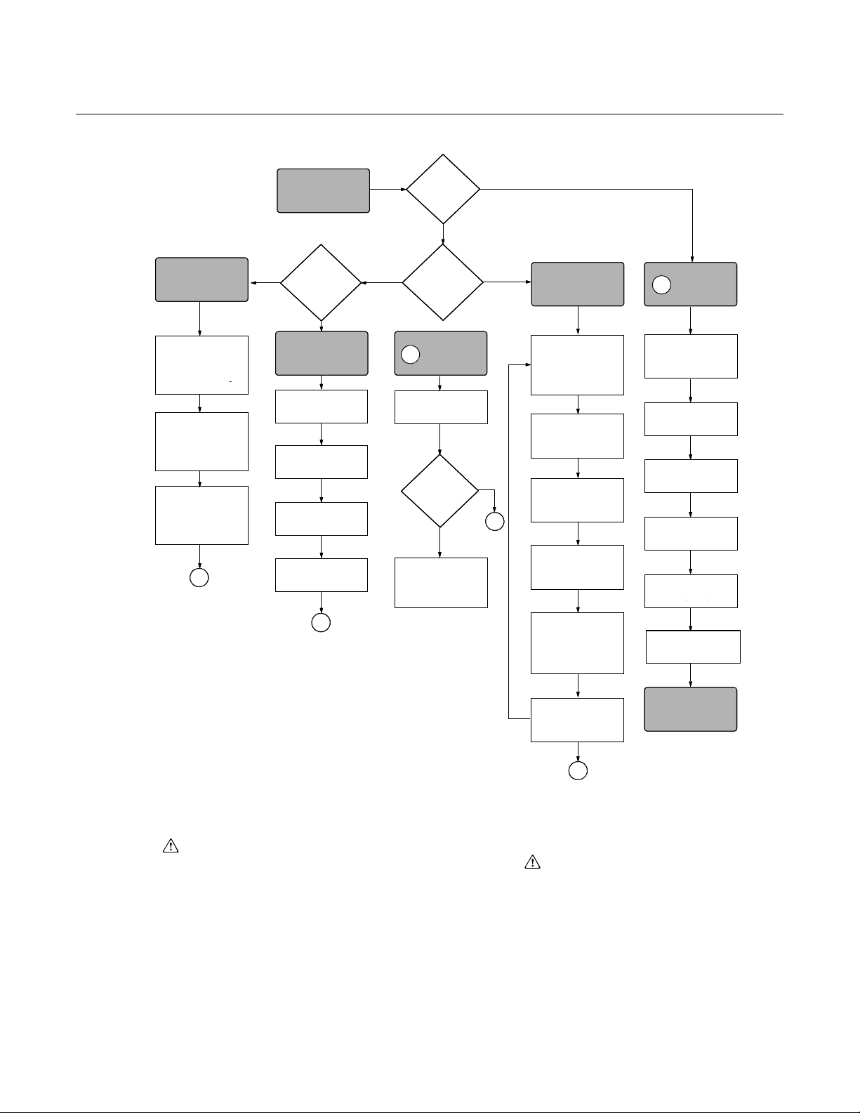
No
No Smart Analog
B
Yes
Yes
A
Yes
A
A
No
Check Jumper
or Switches
Wire
Transmitte
Power
Transmitter
Zero
Transmitter
DONE
Repeat Steps
until
Calibrated
Turn Span Screw
above or below
Desired Output by
Value in Last Step
Mount
Transmitter
Press Both Zero
and Span Button
Simultaneously
Set Units
Set
Range Points
Set
Output Type
Set
Damping
Apply Pressure
Refer to
Section 4
Troubleshooting
Apply Zero Point
Pressure and
Press Zero Button
Apply Span Point
Pressure and Press
Span Button
CONFIGURE
Within
Specification?
VERIFY
START HERE
CALIBRATE
Analog
or
Smart?
Using a
communicator?
FIELD
INSTALL
ADJUST ANALOG
ZERO/SPAN
B
B
Check for Leaks
(Process Connections)
No
No Smart Analog
B
Yes
Yes
A
Yes
A
A
No
Check Jumper
or Switches
Wire
Transmitte
Power
Transmitter
Zero
Transmitter
DONE
Repeat Steps
until
Calibrated
Turn Span Screw
above or below
Desired Output by
Value in Last Step
Mount
Transmitter
Press Both Zero
and Span Button
Simultaneously
Set Units
Set
Range Points
Set
Output Type
Set
Damping
Apply Pressure
Refer to
Section 4
Troubleshooting
Apply Zero Point
Pressure and
Press Zero Button
Apply Span Point
Pressure and Press
Span Button
CONFIGURE VERIFY
START HERE
CALIBRATE
Analog
or
Smart?
Bench
Calibration?
Using a
communicator?
FIELD
INSTALL
ADJUST ANALOG
ZERO/SPAN
B
B
Check for Leaks
(Process Connections)
No
No Smart Analog
B
Yes
Yes
A
Yes
A
A
No
Check Jumper
or Switches
Wire
Transmitter
Power
Transmitter
Zero
Transmitter
DONE
Divide
Difference
by 5
Repeat Steps
until
Calibrated
Turn Span Screw
above or below
Desired Output by
Value in Last Step
Mount
Transmitter
Press Both Zero
and Span Button
Simultaneously
Set Units
Set
Range Points
Set
Output Type
Set
Damping
Apply Pressure
Refer to
Section 4
Troubleshooting
Apply Zero Point
Pressure and
Press Zero Button
Apply Span Point
Pressure and Press
Span Button
CONFIGURE VERIFY
START HERE
CALIBRATE
Analog
or
Smart?
Using a
communicator?
FIELD
INSTALL
ADJUST ANALOG
ZERO/SPAN
B
B
Subtract Actual
Output from Desired
Output
Apply
20 mA-point
Pressure
Apply 4 mA-point
Pressure and Turn
Zero Screw to Output
4 mA
Check for Leaks
(Process Connections)
Figure 2-1. Rosemount 1151 Installation Flowchart.
Reference Manual
00809-0100-4360, Rev BA
August 2008
SAFETY MESSAGES
Warnings ( ) Procedures and instructions in this section that raise potential safety issues
are indicated by a warning symbol ( ). Refer to the following warning
messages before performing an operation preceded by this symbol.
2-2
Page 13
Reference Manual
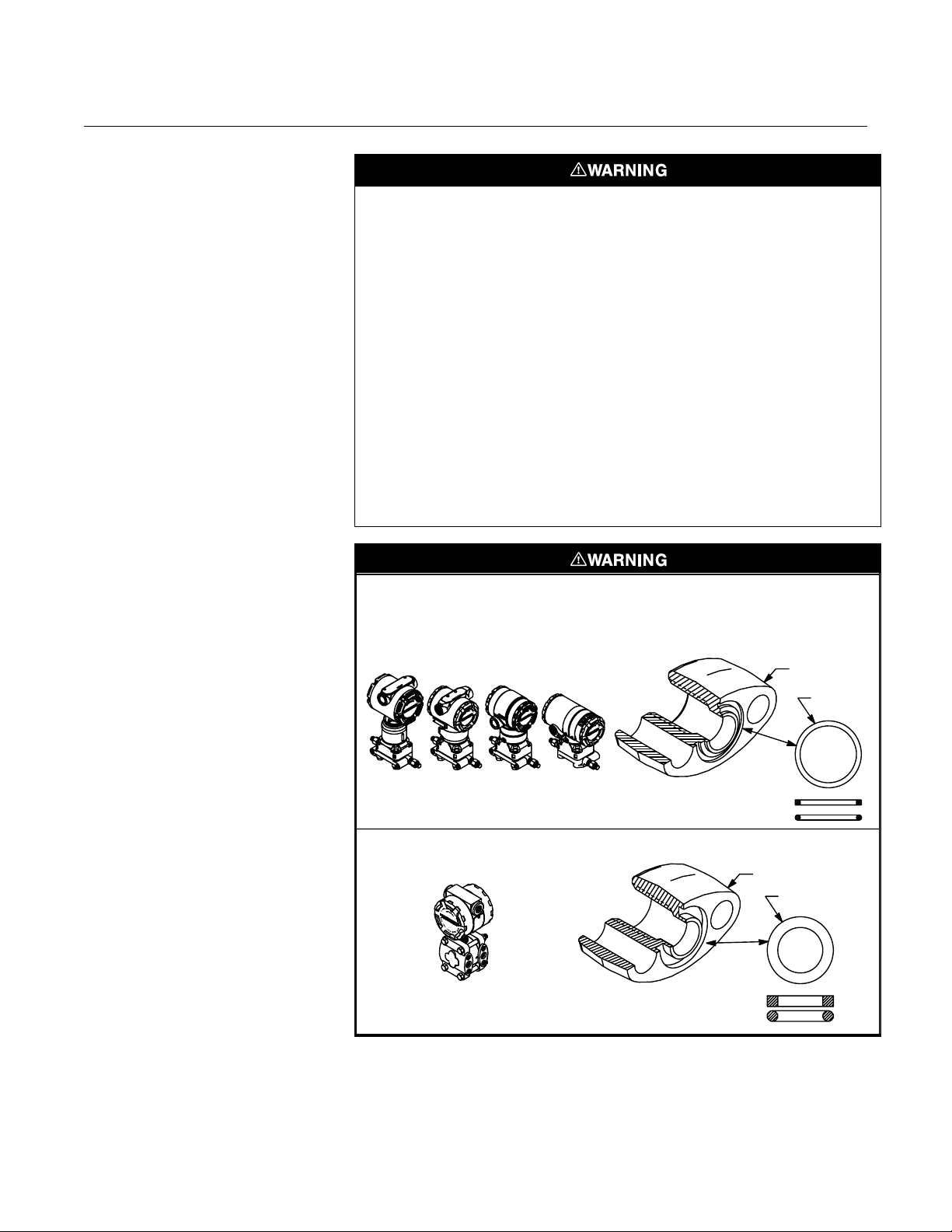
Failure to install proper flange adapter O-rings may cause process leaks, which can result in
death or serious injury. The two flange adapters are distinguished by unique O-ring grooves.
Only use the O-ring that is designed for its specific flange adapter, as shown below.
ROSEMOUNT 3051S / 3051 / 2051 / 3001 / 3095 / 2024
ROSEMOUNT 1151
Flange
Adapter
O-ring
Flange Adapter
O-ring
PTFE Based
Elastomer
PTFE
Elastomer
00809-0100-4360, Rev BA
August 2008
Rosemount 1151
• Explosions can result in death or serious injury. Before connecting a communicator in an
explosive atmosphere, make sure the instruments in the loop are installed in accordance
with intrinsically safe or nonincendive field wiring practice.
• Process leaks can cause death or serious injury. Install and tighten all four flange
bolts before applying pressure, or process leakage may result. Attempting to remove
the flange bolts while the transmitter is in service may cause process fluid leaks.
• All explosion-proof, flameproof, and dust-ignition-proof installations require insertion
of conduit plugs in all unused openings with a minimum of 40 ft-lb (54 N-m) of
torque. This will maintain five full threads of engagement.
• When adding a meter option to a Rosemount 1151 with an Option Code R1 terminal
block, make sure to change to cemented meter covers with a glass window. Make
sure a sticker is located inside the cover that indicates a “cemented cover.” This
cover is required to maintain explosion-proof approval.
• Explosions can cause death or serious injury. Do not remove the instrument cover in
explosive atmospheres when the circuit is alive.
• Explosions can cause death or serious injury. To meet hazardous location
requirements, any transmitter with a tag specifying Option Codes I5, I1, N1, I8, I7, or
N7 requires an intrinsically safe analog display (Part Nos. 01151-2614-0004 through
0009) or an LCD Display (Part Nos. 01151-1300-1000,01151-1300-1001).
2-3
Page 14

Rosemount 1151
Reference Manual
00809-0100-4360, Rev BA
August 2008
GENERAL
CONSIDERATIONS
Transmitter Access
Requirements
The accuracy of a flow, pressure, or level measurement depends on proper
installation of the transmitter and impulse piping. The piping between the
process and transmitter must accurately transmit process pressure to the
transmitter. Mount the transmitter close to the process and use a minimum of
piping to achieve best accuracy. However, keep in mind the need for easy
access, safety of personnel, practical field calibration, and a suitable
transmitter environment.
In general, install the transmitter so as to minimize vibration, shock, and
temperature fluctuations.
Installations in food, beverage, and pharmaceutical processes may require
sanitary seals and fittings. Regulations may dictate special installation
requirements to maintain sanitation and cleanability. See
www.emersonprocess.com for more information about sanitary pressure
instruments.
When choosing an installation location and position, take into account the
need for access to the transmitter.
Process Flange Orientation
Orient the process flanges to enable process connections to be made. For
safety reasons, orient the drain/vent valves so that process fluid is directed
down and away from technicians when the valves are used. This can be
accomplished by pointing the hole in the outside valve body downward and
away.
Housing Rotation
Do not rotate the transmitter housing more than 90 degrees without disconnecting the
header board. Exceeding 90 degrees rotation will damage the internal sensor module
wiring.
The electronics housing is designed to be rotated up to 90 degrees in order to
provide field access to the two housing compartments. (If rotating the housing
more than 90 degrees is necessary, follow the transmitter disassembly
procedures in Section 5: Troubleshooting.) To rotate the housing up to 90
degrees, loosen the housing lock nut and turn the housing not more than 90
degrees.
NOTE
Seal module threads with Loctite
(see Connecting the Electrical Housing to the Sensor on page 5-7.)
Terminal Side of
Electronics Housing
The terminal side is marked on the nameplate located on the side of the
transmitter. Mount the transmitter so that the terminal side of the housing is
accessible by providing:
3
/4-inch clearance for cover removal with no meter
•A
• A 3-inch clearance for cover removal with a meter installed
®
222 before retightening housing lock nut
2-4
Page 15

Reference Manual
00809-0100-4360, Rev BA
August 2008
Rosemount 1151
If practical, provide approximately 6 inches clearance so that a meter may be
installed later.
Circuit Side of
Electronics Housing
The circuit compartment should not routinely need to be opened when the unit
is in service. However, provide 6 inches clearance, if possible, to allow access
to the integral zero and span buttons or for on-site maintenance. The circuit
side of the housing is marked on the nameplate located on the side of the
transmitter.
Exterior of Electronics Housing
The Rosemount 1151 Smart Pressure Transmitter uses the same housing as
the Rosemount 1151 Analog. For this reason, integral span and zero
screws—non-functional on the Rosemount 1151 Smart Pressure
Transmitter—are located under the nameplate on the side of the transmitter.
2-5
Page 16
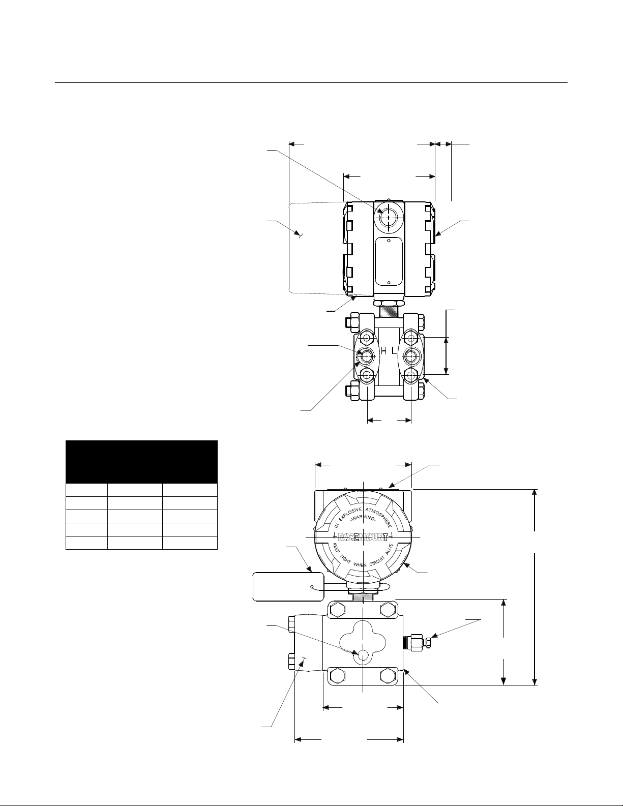
Rosemount 1151
Range
Flange Distance “A”
Center to Center
inches mm
3, 4, 5 2.125 54
6, 7 2.188 56
8 2.250 57
9 2.281 58
0 2.328 59
½–14 NPT
Conduit
Connection
(2 Places)
Meter
Housing
Terminal Connections
This Side
¼–18 NPT on
Flanges for Pressure
Connection without
Flange Adapters
½–14 NPT on
Flange
Adapters
A
(See Table)
4.5 (114)
Max.
7.5 (191) Max.
with Optional Meter
0.75 (19)
Clearance for
Cover Removal
(Typical)
Transmitter
Circuitry
This Side
1.625
(41)
Blank Flange
Used on
AP and GP
Transmitters
Flange
Adapter
4.5 (114)
3.375
(86)
Flanges Can
Be Rotated
3.69
(94)
4.5 (114)
Max.
Permanent
Tag (Optional)
9.0 (229) Max.
Nameplate
Wired-on
Tag
(Standard)
Drain/Vent
Valve
¼–18 NPT for
Side Drain/Vent
(Optional Top
or Bottom)
NOTE
Dimensions are in inches (millimeters).
Figure 2-2. Rosemount
1151AP, DP, GP, and HP
Dimensional Drawings.
MECHANICAL CONSIDERATIONS
Dimensional Drawings
Reference Manual
00809-0100-4360, Rev BA
August 2008
2-6
Page 17
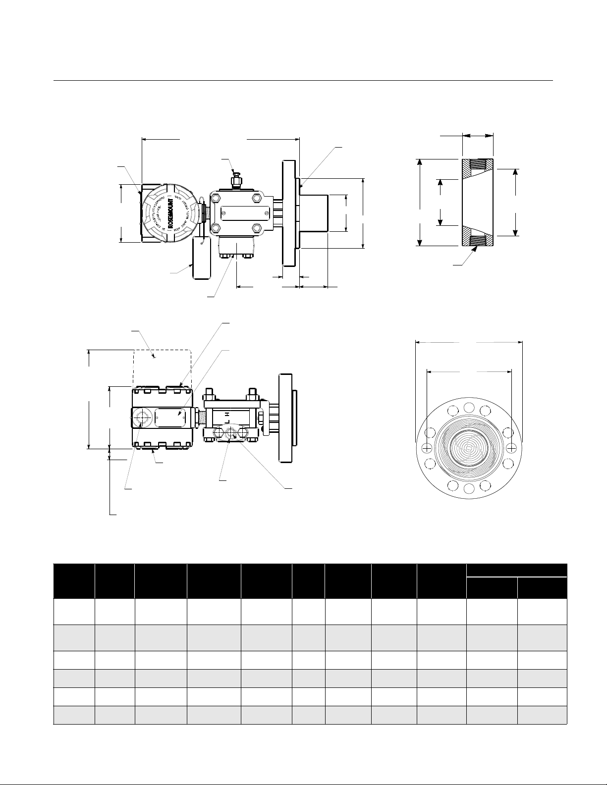
Reference Manual
C
B
DIAPHRAGM ASSEMBLY
AND MOUNTING FLANGE
NOTE
Dimensions are in inches (millimeters).
Permanent Tag
(optional)
11.38 (289) Max.
Serrated Face
Gasket Surface
E
D
A
Wired-on Tag
(standard)
Flange
Adapter
2-, 4-, or 6-in.
(51, 102, or 152)
Extension
4.5
(114)
Max.
4.45
(113)
Max.
Flushing
Connection
1
(25)
F
G
E
OPTIONAL FLUSHING
CONNECTION RING
(LOWER HOUSING)
Meter
Housing
Terminal Connections
This Side
Nameplate (Remove for
Span and Zero Adjust)
Transmitter
Circuitry
This Side
½–14 NPT for
Conduit Connection
(2 places)
0.75 (19) Clearance for
Cover Removal (typical)
½–14 NPT
on Flange
Adapters
¼–18 NPT on Flanges
for Pressure Connection
without the Use of Flange
Adapters
4.5 (114)
Max.
7.5 (190.5)
Max. with
Optional
Meter
Figure 2-3. Rosemount 1151LT Dimensional Drawing.
00809-0100-4360, Rev BA
August 2008
Rosemount 1151
Table 2-1. Rosemount 1151LT Dimensional Specifications
Pipe
Size
3 (76)
4 (102)
3 (76)
4 (102)
3 (76)
DN 50 26 mm 125 mm 165 mm 4 18 mm NA 95 mm 74 mm 55 mm
DN 80
DN 100
DN 100 26 mm 180 mm 220 mm 8 18 mm 89 mm 173 mm 103 mm 103 mm
Class
ANSI 150 2 (51)
ANSI 300 2 (51)
ANSI 600 2 (51)
DIN
PN10-40
DIN
PN 25/40
DIN
PN 10/16
(1) Tolerances are 0.040 (1.02), –0.020 (0.51).
Thickness A
Flange
1.12 (28)
1.31 (33)
1.31 (33)
1.25 (32)
1.50 (38)
1.62 (41)
1.12 (28)
1.37 (35)
30 mm
30 mm
Bolt Circle
Diameter B
4.75 (121)
6.0 (152)
7.5 (190)
5.0 (127)
6.62 (168)
7.88 (200)
5.0 (127)
6.62 (168)
160 mm
190 mm
Outside
Diameter C
6.0 (152)
7.5 (190)
9.0 (228)
6.5 (165)
8.25 (209)
10.0 (254)
6.5 (165)
6.62 (168)
200 mm
235 mm
No. of
Bolts
4
4
8
8
8
8
8
8
8
8
Bolt Hole
Diameter
0.75 (19)
0.75 (19)
0.75 (19)
0.75 (19)
0.88 (22)
0.88 (22)
0.75 (19)
0.88 (22)NA2.58 (65)
18 mm
22 mm
Exten.
(1)
Diam. D
NA
2.58 (65)
3.5 (89)
NA
2.58 (65)
3.5 (89)
65 mm
89 mm
O.D.
Gask. Surf. E
3.75 (95)
5.0 (127)
6.81 (173)
3.75 (95)
5.0 (127)
6.81 (173)
3.75 (95)
5.0 (127)
127 mm
173 mm
Lower Housing
Xmtr
Side F
2.9 (74)
3.11 (79)
4.06 (103)
2.9 (74)
3.11 (79)
4.06 (103)
2.9 (74)
3.11 (79)
79 mm
103 mm
Proc.
Side G
2.16 (55)
3.11 (79)
4.06 (103)
2.16 (55)
3.11 (79)
4.06 (103)
2.16 (55)
3.11 (79)
79 mm
103 mm
2-7
Page 18

Rosemount 1151
Reference Manual
00809-0100-4360, Rev BA
August 2008
MOUNTING
CONSIDERATIONS
Mounting Requirements
(for Steam, Liquid, Gas)
The Rosemount 1151 Pressure Transmitter weighs 12 lb. (5.4 kg) without a
meter and 15 lb. (6.8 kg) with a meter. This weight must be securely
supported. The transmitter is calibrated in an upright position at the factory. If
this orientation is changed during mounting, the zero point will shift by an
amount equivalent to the liquid head caused by the mounting position. For
Smart Transmitters, follow “Because a zero trim must be zero-based, it
generally should not be used with Rosemount 1151 Smart Absolute Pressure
Transmitters. Absolute pressure transmitters reference absolute zero. To
correct mounting position effects on a Rosemount 1151 Smart Absolute
Pressure Transmitter, perform a low trim within the full sensor trim function.
The low trim function provides a “zero” correction similar to the zero trim
function but it does not require the input to be zero based.” on page 4-5 to
correct this shift. For Analog Transmitters, follow “Zero and Span Adjustment”
on page 4-15 to correct this shift.
NOTE
Do not plug the low side with a solid plug. Plugging the low side will cause an
output shift.
The following information applies to steam, liquid, and gas installations.
Taps
Tap placement is dependent on the type of process being measured, and on
whether the transmitter has side drain/vent valves:
• For liquid flow measurement, place taps to the side of the line to
prevent sediment deposits, and mount the transmitter beside or below
these taps so gases can vent into the process line and away from the
transmitter.
• For gas flow measurement, place taps in the top or side of the line and
mount the transmitter beside or above the taps so liquid will drain away
from the transmitter.
• For steam flow measurement, place taps to the side of the line with the
transmitter mounted below them to ensure that the impulse piping stays
filled with condensate.
• For transmitters with side drain/vent valves, place taps to the side of
the line.
2-8
See Figure 2-4 for a diagram of these arrangements.
Page 19
Reference Manual
NOTE
For steam service do not blow down impulse piping
through transmitter. Flush lines with blocking valves closed
and refill lines with water before resuming measurement.
Plugged Tee
for Steam Service
for Sealing Fluid
STEAM SERVICE
Sufficient
Length for
Cooling
Blocking
Valves
3-valve
Manifold
Flow
Vent/Drain
Valve
3-valve
Manifold
GAS SERVICE
Flow
3-valve
Manifold
Drain/Vent
Valve
Flow
Optional
Side-mounted
Drain/Vent Valve
3-valve
Manifold
Flow
Figure 2-4. Steam, Liquid, and
Gas Service Installation Diagrams.
H
L
LIQUID SERVICE
H
H
H
L
L
L
00809-0100-4360, Rev BA
August 2008
Rosemount 1151
2-9
Page 20

Rosemount 1151
Reference Manual
00809-0100-4360, Rev BA
August 2008
Drain/Vent Va lves
Drain/vent valve orientation is also dependent on the process being
measured:
• For liquid service, mount the side drain/vent valve upward to allow the
gases to vent.
• For gas service, mount the drain/vent valve down to allow any
accumulated liquid to drain.
To change the drain/vent valve orientation from top to bottom, rotate the
process flange 180 degrees.
Impulse Piping
The piping between the process and the transmitter must accurately transfer
the pressure in order to obtain accurate measurements. In this pressure
transfer, there are five possible sources of error:
•Leaks
• Friction loss (particularly if purging is used)
• Trapped gas in a liquid line
• Liquid in a gas line
• Temperature-induced or other density variation between the legs
The best location for the transmitter in relation to the process pipe depends on
the process itself. Consider the following general guidelines in determining
transmitter location and placement of impulse piping:
• Keep impulse piping as short as possible.
• Slope the impulse piping at least 1 inch per foot (8 centimeters per
meter) upward from the transmitter toward the process connection for
liquid.
• Slope the impulse piping at least 1 inch per foot (8 centimeters per
meter) downward from the transmitter toward the process connection
for gas.
• Avoid high points in liquid lines and low points in gas lines.
• Make sure both impulse legs are the same temperature.
• Use impulse piping large enough to avoid friction effects and prevent
blockage.
• Vent all gas from liquid piping legs.
• For steam service, fill impulse piping with water to prevent contact of
live steam with the transmitter.
Steam or other elevated temperature processes can cause damage to the sensor. Do
not allow the temperature inside the process flanges to exceed the transmitter limit of
220 °F (104 °C).
2-10
Page 21

Reference Manual
Rosemount 3051/2024/3001/3095/2051
Rosemount 1151
Flange Adapter
Flange Adapter
O-ring
Unique O-ring
Grooves
O-ring
00809-0100-4360, Rev BA
August 2008
• When using a sealing fluid, fill both piping legs to the same level.
• When purging is necessary, make the purge connection close to the
process taps and purge through equal lengths of the same size pipe.
Avoid purging through the transmitter.
• Keep corrosive or hot process material out of direct contact with the
sensor module and flanges.
• Prevent sediment deposits in the impulse piping.
• Keep the liquid head balanced on both legs of the impulse piping.
Process Connections Flange Adaptors:
Rosemount 1151
Figure 2-5. O-Rings.
Rosemount 1151AP, DP, GP, and HP process connections on the transmitter
1
flanges are
/4–18 NPT. Flange adapters are available with standard 1/2–14
NPT Class 2 connections. The flange adapters allow users to disconnect from
the process by removing the flange adapter bolts. Use plant-approved
lubricant or sealant when making the process connections. Figure 2-2 shows
1
the distance between pressure connections. This distance may be varied ±
/8
in. (3.2 mm) by rotating one or both of the flange adapters.
On open vessels, the low-side process flange is open to atmosphere and
should be mounted with the threaded hole pointed down. On closed vessels,
this connection is used for the dry or wet leg.
High-pressure-side process connections for the Rosemount 1151LT
Transmitter are offered with 2-, 3-, or 4-in., Class 150, 300, or 600 flanges; DN
50 (PN 10-40), DN 80 (PN 25/40), or DN 100 (PN 10/16, 25/40).
Low-pressure-side process connections for the Rosemount 1151LT
Transmitter are offered with ¼–18 NPT on the flange, and ½–14 NPT on the
adapter.
O-rings:
The two styles of Rosemount flange adapters (Rosemount 1151 and
Rosemount 3051/2024/3001/3095/2051) each require a unique O-ring (see
Figure 2-5). Use only the O-ring designed for the corresponding flange
adaptor.
When compressed, PTFE O-rings tend to “cold flow,” which aids in their
sealing capabilities.
2-11
Page 22

Reference Manual
00809-0100-4360, Rev BA
Rosemount 1151
August 2008
NOTE
PTFE O-rings should be replaced if the flange adapter is removed.
Tightening the Seal:
To ensure a tight seal on the flange adapters or a three-valve manifold, first
finger-tighten both bolts, then wrench-tighten the first bolt to approximately 29
ft.-lbs (39 N-m). Wrench-tighten the second bolt to approximately 29 ft.-lbs (39
N-m).
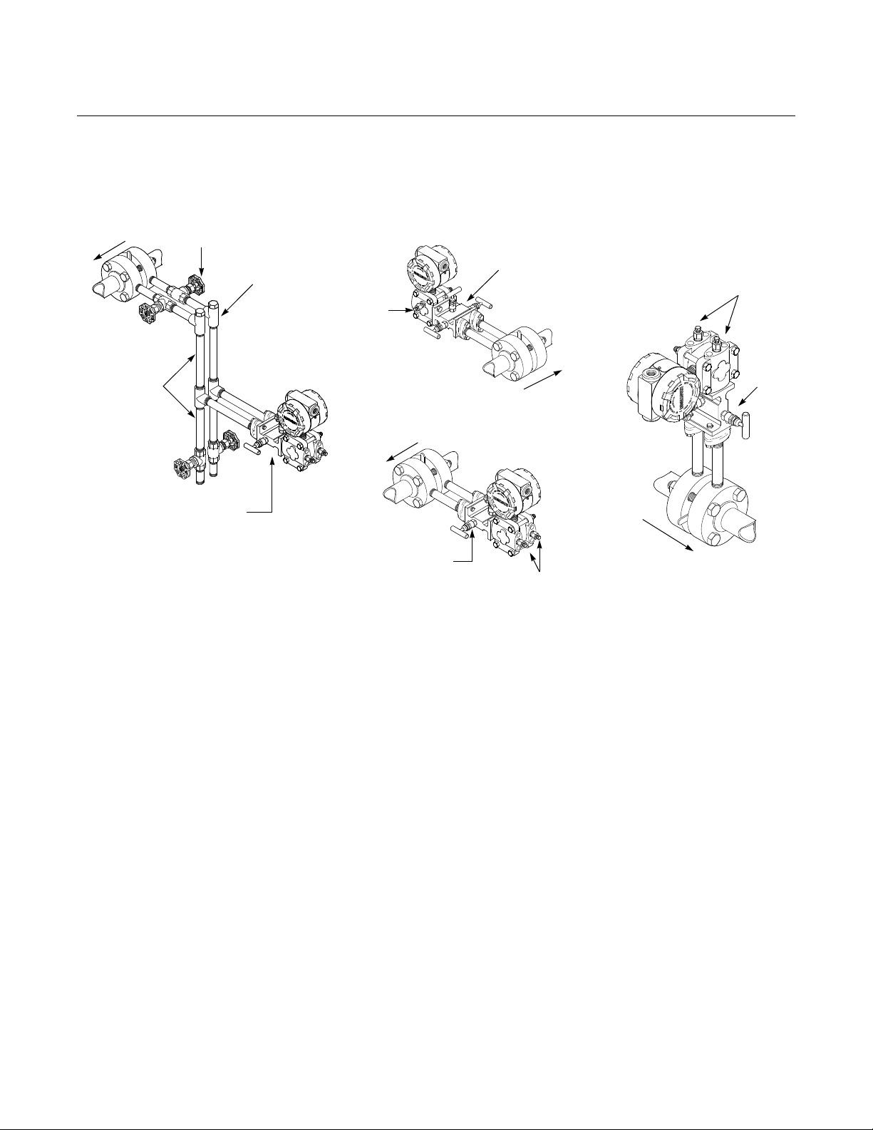
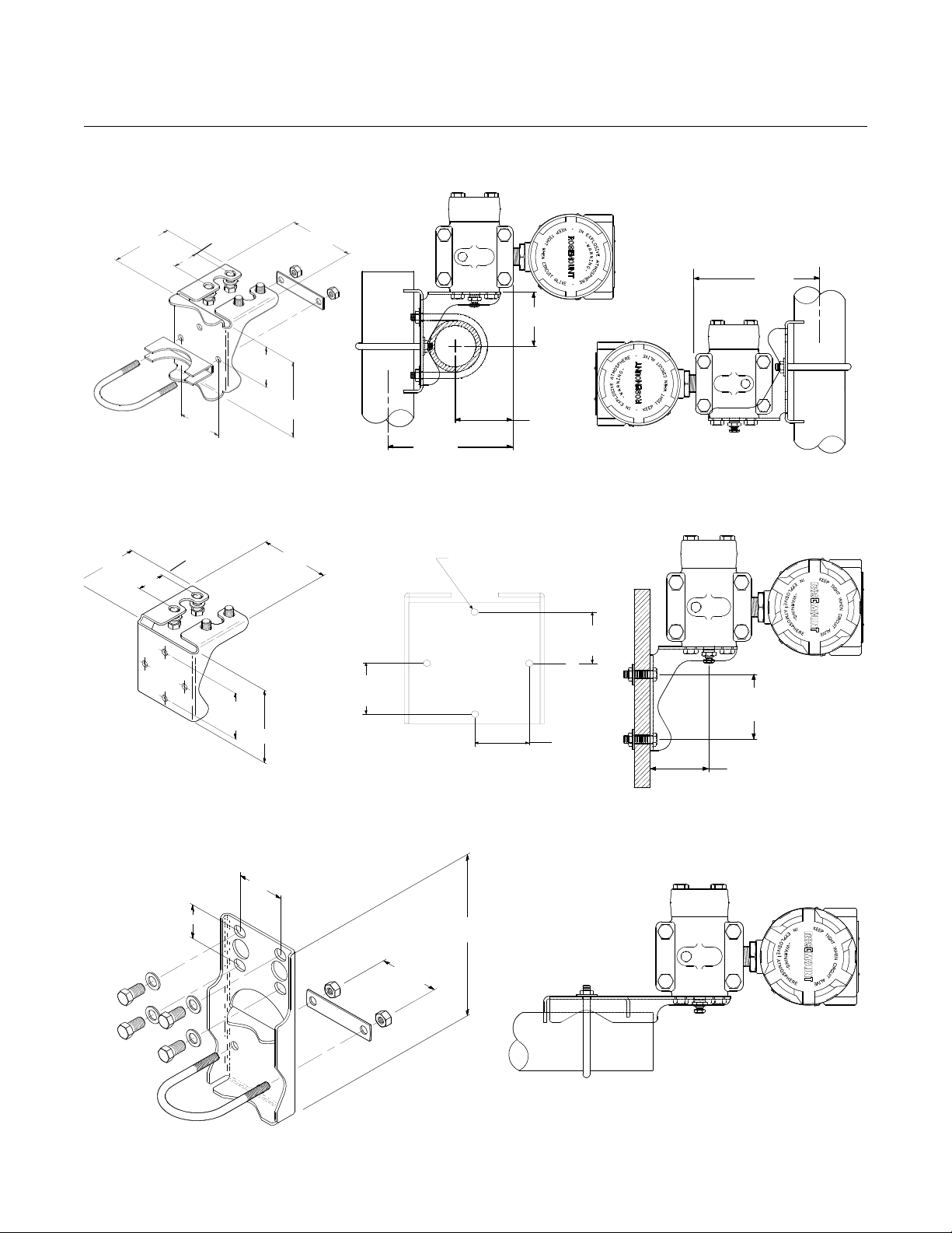
Mounting Brackets Optional mounting brackets permit mounting the transmitter to a wall, a panel,
or a 2-inch horizontal or vertical pipe. Figure 2-6 illustrates some typical
configurations these mounting brackets.
Table 2-2. Mounting Brackets
Mounting Material
Pipe
Option Code
B1 X X X
B3 X X X
B4 X X X
B6 X X X
B7 X X X
B9 X X X
Mount
Panel
Mount
CS
Bracket
SST
Bracket
CS
Bolts
SST Bolts
2-12
Page 23
Reference Manual
3.87 (98)
3.75 (95)
1.65 (42)
2.62 (67)
4.97
(127)
2.81
(71)
2.625
(67)
5.625
(143)
2.625 (67)
2.625
(67)
1.65 (42)
3.87 (98)
4.5 (114)
1.40 (36)
Mounting Holes
0.375 Diameter
(10)
3.75 (95)
2.81
(71)
2.125 (54)
2.81 (71)
8 (203)
NOTE
Dimensions are in inches (millimeters).
1.62 (41)
5.625
(143)
Figure 2-6. Mounting Bracket Option Codes B1, B4, and B7.
1.40
(36)
1.40
(36)
2.81 Typ.
(71)
Figure 2-8. Flat Mounting Bracket Option Codes B3, B6, and B9
Figure 2-7. Panel Mounting Bracket Option Codes B2, and B5
00809-0100-4360, Rev BA
August 2008
Rosemount 1151
2-13
Page 24

Rosemount 1151
Code V
min
V
max
R
min
R
max
RL at Supply Voltage (Vs)
S
(1)
(1) A minimum of 250 ohms is required for communication.
12 45 0 1650 RL = 43.5 (VS–12)
E
(2)
(2) For CSA Approvals (code E), V
max
= 42.4 V dc.
12 45 0 1650 RL = 50 (VS – 12)
G308501100 R
L
= 20 (VS – 30)
L 5 12 Low Power Minimum Load Impedance:
100 k
M814
R
max
R
L
R
min
V
min
V
S
V
max
Operating
Region
Reference Manual
00809-0100-4360, Rev BA
August 2008
ELECTRICAL
CONSIDERATIONS
NOTE
Make sure all electrical installation is in accordance with national and local
code requirements.
Power Supply The DC power supply should provide power with less than 2% ripple. The
total load is the sum of the resistance of the signal leads and the load
resistance of the controller, indicator, and related pieces. The resistance of
intrinsic safety barriers, if used, must be included. Figure 2-7 illustrates power
supply load limitations for the transmitter.
Figure 2-7. Power Supply Load
Limitations.
Conduit Installation
2-14
If all connections are not sealed, excess moisture accumulation can damage the
transmitter. Make sure to mount the transmitter with the electrical housing positioned
downward for drainage. To avoid moisture accumulation in the housing, install wiring
with a drip loop, and ensure the bottom of the drip loop is mounted lower than the
conduit connections or the transmitter housing.
Recommended conduit connections are shown in Figure 2-8.
Page 25
Reference Manual
Sealing
Compound
Conduit
Lines
CORRECT CORRECT INCORRECT
Possible
Conduit Line
Positions
Sealing
Compound
Possible
Conduit Line
Positions
00809-0100-4360, Rev BA
August 2008
Figure 2-8. Conduit Installation
Diagrams.
Wiring
Rosemount 1151
Do not connect the power signal wiring to the test terminals. Voltage may burn out the
reverse-polarity protection diode in the test connection. If the test diode is destroyed,
then the transmitter can still be operated without local indication by jumping the test
terminals.
High voltage (greater than 50 V and greater than 0.005 amperes) can cause
damage to the transmitter. Do not apply high voltage to the test terminals.
The signal terminals and test terminals are located in a compartment of the
electronics housing that is separate from the transmitter electronics. The
nameplate on the side of the transmitter indicates the locations of both of
these compartments. The upper pair of terminals are the signal terminals and
the lower pair are the test terminals. The test terminals have the same 4–20
mA output as the signal terminals and are only for use with the optional
integral meter or for testing.
NOTE
An alternate location to connect an ammeter is on the set of terminals labeled
“TEST.” Connect the positive lead of the ammeter to the positive test terminal,
and the negative lead of the ammeter to the negative test terminal.
To make connections, remove the cover on the side marked “Terminal” on the
nameplate. All power to the transmitter is supplied over the signal wiring.
Connect the lead that originates at the positive side of the power supply to the
terminal marked “+” and the lead that originates at the negative side of the
power supply to the terminal marked “–”. No additional wiring is required.
Do not run signal wiring in conduit or open trays with power wiring or near
heavy electrical equipment.
For improved performance against EMI/RFI effects, refer to “Terminal Blocks”
on page 2-24 for information on transient protection terminal blocks.
2-15
Page 26

Reference Manual
00809-0100-4360, Rev BA
Rosemount 1151
Shielded cable should be used for best results in electrically noisy
environments. Refer to “Grounding” on page 2-16 for more details.
NOTE
When conduit lines are used, signal wiring need not be shielded, but twisted
pairs should be used for best results. Wiring must be 24 AWG or larger and
not exceed 5,000 feet (1500 meters).
NOTE
A minimum loop resistance of 250
hand-held HART-based communicator. With 250
transmitter requires a minimum of 17 volts to output 20 mA. If a single power
supply is used to power more than one Rosemount 1151 Smart transmitter,
the power supply used, and circuitry common to the transmitters should not
have more than 20 of impedance at 1200 Hz.
is required to communicate with a
of loop resistance, the
August 2008
Grounding Use the following techniques to properly ground the transmitter signal wiring
and case:
Signal Wiring
Do not run signal wiring in conduit or open trays with power wiring or near
heavy electrical equipment. It is important that the instrument cable shield be:
• Trimmed close and insulated from touching the transmitter housing
• Connected to the next shield if cable is routed through a junction box
• Connected to a good earth ground at the power supply end
Signal wiring may be grounded at any one point on the signal loop or may be
left ungrounded. The negative terminal of the power supply is a
recommended grounding point.
Transmitter Case
The transmitter case must be grounded in accordance with national and local
electrical codes. The most effective transmitter case grounding method is a
direct internal connection to earth ground with minimal impedance. The
transmitter case may also be grounded through the process or conduit
connections.
Internal Ground Connection: Inside the field terminals side of the
electronics housing is the internal ground connection screw. This screw is
identified by a ground symbol: .
NOTE
Grounding the transmitter case via threaded conduit connection may not
provide sufficient ground continuity.
2-16
NOTE
The transient protection terminal block (page 2-25) does not provide transient
protection unless the transmitter case is properly grounded. Use the
preceding guidelines to ground the transmitter case.
Do not run the transient protection ground wire with signal wiring as the
ground wire may carry excessive current if a lightning strike occurs.
Page 27
Reference Manual
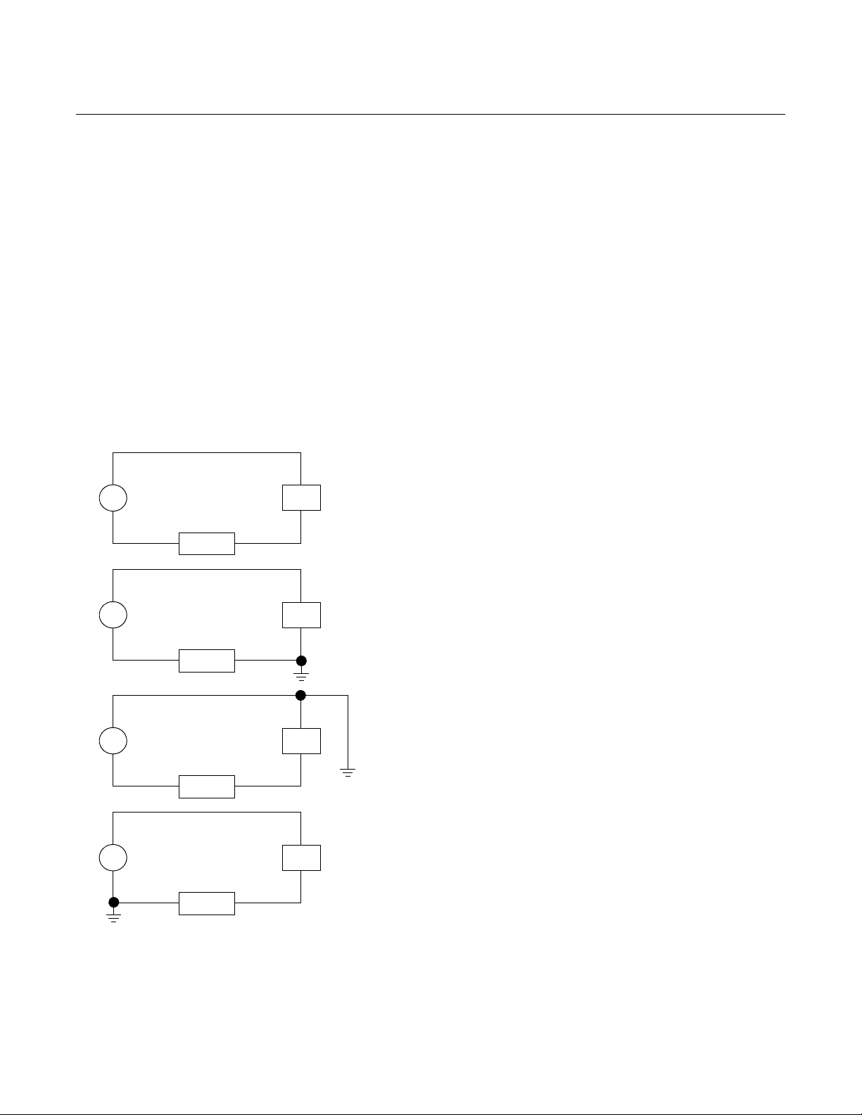
PT
LOAD
PS
+
–
Ungrounded System
Impressed Voltage: 12 to 22 mV
p-p
32 kHz
Effect: 0.01% of span, max.
PT
LOAD
PS
+
–
PT
LOAD
PS
+
–
PT
LOAD
PS
+
–
Ground Between Negative Side of Power Supply and Load
Impressed Voltage: 35 to 60 mVp-p
32 kHz
Effect: 0.03% of span, max.
Ground Between Positive Side of Transmitter and Power Supply
Impressed Voltage: 35 to 60 mVp-p
32 kHz
Effect: 0.03% of span, max.
Ground Between Negative Terminal of Transmitter and Load
Impressed Voltage: 500 to 600 mVp-p
32 kHz
Effect: 0.27% of span, max.
*The effect caused by the impressed voltage on a computer with a sampling time
of 100 microseconds using a 2 to 10 volt signal.
00809-0100-4360, Rev BA
August 2008
Figure 2-9. Effects of Grounding
on Accuracy for Fast Sample
Computers.
Rosemount 1151
Grounding Effects
The capacitance sensing module requires alternating current to generate a
capacitance signal. This alternating current is developed in an oscillator circuit
with a frequency of approximately 32 kHz. This signal is capacitor-coupled to
transmitter-case ground through the sensing module. Because of this
coupling, a voltage may be imposed across the load, depending on the choice
of grounding. See Figure 2-9.
Impressed voltage, which is seen as high frequency noise, will have no effect
on most instruments. Computers with short sampling times in circuits will
detect a significant noise signal, which should be filtered out by using a large
capacitor (1 μF) or by using a 32 kHz LC filter across the load. Computers that
are wired and grounded, as shown in Figure 2-9, are negligibly affected by
this noise and do not need filtering.
2-17
Page 28

Rosemount 1151
Reference Manual
00809-0100-4360, Rev BA
August 2008
Hazardous Locations
Certifications
Environmental
Requirements
LIQUID LEVEL
MEASUREMENT
Open Vessels
The Rosemount 1151 was designed with an explosion-proof housing and
circuitry suitable for intrinsically safe and nonincendive operation. Factory
Mutual explosion-proof certification is standard for the Rosemount 1151
Transmitter. Individual transmitters are clearly marked with a tag indicating the
approvals they carry. Transmitters must be installed in accordance with all
applicable codes and standards to maintain these certified ratings. Refer to
“Hazardous Locations Certifications” on page B-2 for information on these
approvals.
Mount the transmitter in an environment that has minimal ambient
temperature change. The transmitter electronics temperature operating limits
are –40 to 185 °F (–40 to 85 °C). Refer to Section A: Reference Information
that lists the sensing element operating limits. Mount the transmitter so that it
is not susceptible to vibration and mechanical shock and does not have
external contact with corrosive materials.
Differential pressure transmitters used for liquid level applications measure
hydrostatic pressure head. Liquid level and specific gravity of a liquid are
factors in determining pressure head. This pressure is equal to the liquid
height above the tap multiplied by the specific gravity of the liquid. Pressure
head is independent of volume or vessel shape.
A pressure transmitter mounted near a tank bottom measures the pressure of
the liquid above.
Make a connection to the high pressure side of the transmitter, and vent the
low pressure side to the atmosphere. Pressure head equals the liquid’s
specific gravity multiplied by the liquid height above the tap.
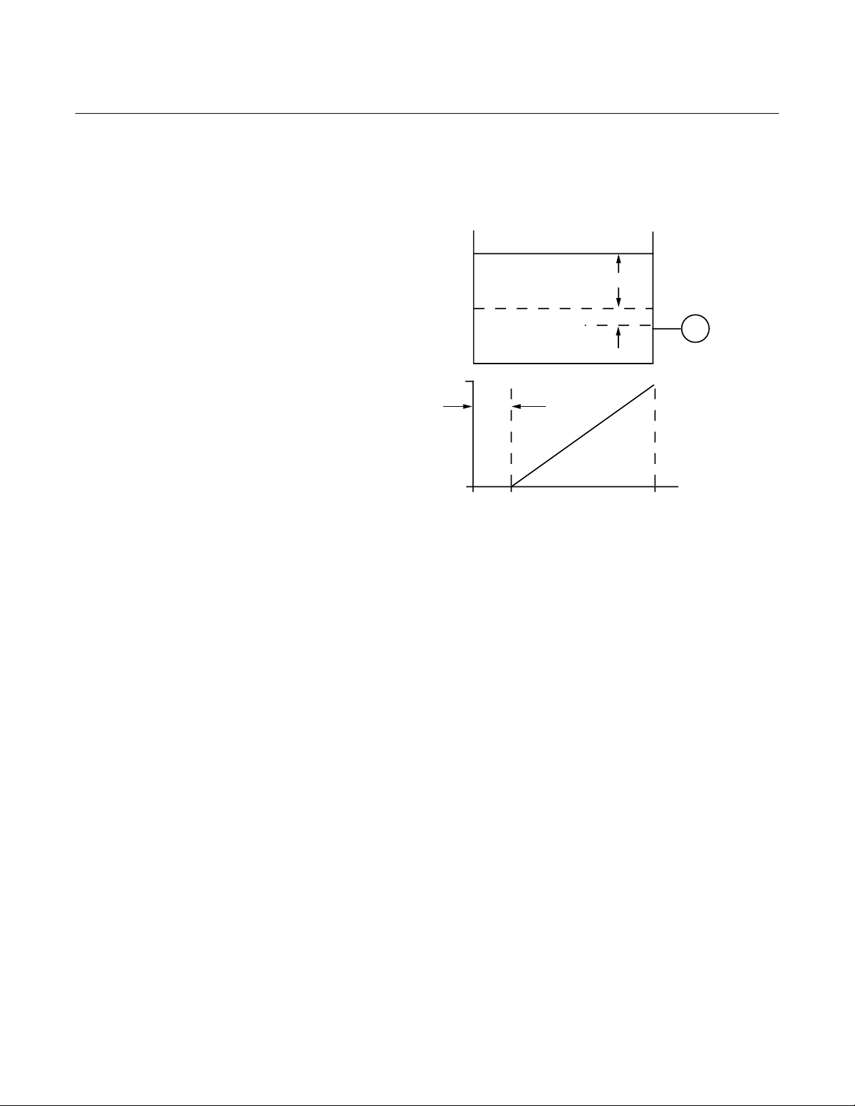
Zero range suppression is required if the transmitter lies below the zero point
of the desired level range. Figure 2-10 shows a liquid level measurement
example.
Closed Vessels Pressure above a liquid affects the pressure measured at the bottom of a
closed vessel. The liquid specific gravity multiplied by the liquid height plus
the vessel pressure equals the pressure at the bottom of the vessel.
To measure true level, the vessel pressure must be subtracted from the
vessel bottom pressure. To do this, make a pressure tap at the top of the
vessel and connect this to the low side of the transmitter. Vessel pressure is
then equally applied to both the high and low sides of the transmitter. The
resulting differential pressure is proportional to liquid height multiplied by the
liquid specific gravity.
2-18
Page 29
Reference Manual
ZERO
SUPRESSION
mA dc
20
540
900
inH2O
4
Figure 2-10. Liquid Level
Measurement Example.
Let X equal the vertical distance between the minimum and maximum
measurable levels (500 in.).
Let Y equal the vertical distance between the transmitter datum line and the
minimum measurable level (100 in.).
Let SG equal the specific gravity of the fluid (0.9).
Let h equal the maximum head pressure to be measured in inches of water.
Let e equal head pressure produced by Y expressed in inches of water.
Let Range equal e to e + h.
Then h = (X)(SG)
= 500 x 0.9
= 450 inH
2
O
e= (Y)(SG)
= 100 x 0.9
=90 inH
2
O
Range = 90 to 540 inH
2
O
T
Y
X
00809-0100-4360, Rev BA
August 2008
Rosemount 1151
Dry Leg Condition
Low-side transmitter piping will remain empty if gas above the liquid does not
condense. This is a dry leg condition. Range determination calculations are
the same as those described for bottom-mounted transmitters in open
vessels, as shown in Figure 2-10.
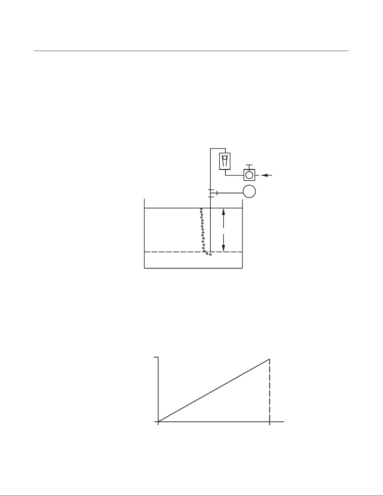
Wet Leg Condition
Condensation of the gas above the liquid slowly causes the low side of the
transmitter piping to fill with liquid. The pipe is purposely filled with a
convenient reference fluid to eliminate this potential error. This is a wet leg
condition.
The reference fluid will exert a head pressure on the low side of the
transmitter. Zero elevation of the range must then be made. See Figure 2-11.
2-19
Page 30
Rosemount 1151
Figure 2-11. Bubbler Liquid Level
Measurement Example.
mA dc
Let X equal the vertical distance between the minimum and maximum
measurable levels (100 in.).
Let SG equal the specific gravity of the fluid (1.1).
Let h equal the maximum head pressure to be measured in inches of water.
Let Range equal zero to h.
Then h = (X)(SG)
= 100 x 1.1
= 110 inH
2
O
Range = 0 to 110 inH
2
O
20
inH2O
0
4
110
T
AIR
X
Reference Manual
00809-0100-4360, Rev BA
August 2008
Bubbler System in Open Vessel
A bubbler system that has a top-mounted pressure transmitter can be used in
open vessels. This system consists of an air supply, pressure regulator,
constant flow meter, pressure transmitter, and a tube that extends down into
the vessel.
Bubble air through the tube at a constant flow rate. The pressure required to
maintain flow equals the liquid’s specific gravity multiplied by the vertical
height of the liquid above the tube opening. Figure 2-11 shows a bubbler
liquid level measurement example.
2-20
Page 31

Reference Manual
Retaining
Ring
Right Configuration
Button
Left Configuration
Button
Analog
Bar Graph
Figure 2-12. LCD Display.
00809-0100-4360, Rev BA
August 2008
Rosemount 1151
INSTALLATION
OPTIONS
Analog Displays Option Codes M1, M2, and M6 provide local indication of the transmitter
output in a variety of scaling configurations with an indicator accuracy of ±2
percent. The plug-in mounting configuration allows for simple installation and
removal of the analog displays. The meter scaling options are shown below.
M1 Linear analog display, 0–100% scale
M2 Square-root analog display, 0–100% flow scale
M6 Square-root analog display, 0–
10√ scale
LCD Displays The LCD Display Option Codes, M4 and M7–M9, provide a highly accurate
local display of the process variable. A variety of scaling configurations are
available and listed as follows:
M4 Linear LCD Display, 0 to 100%
M7 Special scale LCD Display (specify range, mode, and
engineering units)
M8 Square-root LCD Display, 0 to 100%
M9 Square-root LCD Display, 0 to 10%
LCD Display Configuration
The Rosemount LCD Display has four digits and plugs directly into the
Rosemount 1151 Smart Pressure Transmitter to provide a highly accurate
digital display of the process variable. This manual explains the configuration
and assembly of the LCD Display and includes the applicable functional,
performance, and physical specifications. This meter adds no voltage drop in
the 4–20 mA current loop when connected directly across the transmitter test
terminals.
The LCD Display may be configured to meet specific requirements by using
the left and right calibration buttons located on the meter face as shown in
Figure 2-12. The LCD Display cannot be configured for reverse flow because
the 20 mA value must always be greater than the 4 mA value. The analog bar
graph is also shown in Figure 2-12. The 20-segment bar graph is factory
calibrated and represents 4–20 mA directly.
2-21
Page 32

Rosemount 1151
Reference Manual
00809-0100-4360, Rev BA
August 2008
No calibration equipment is required to configure the LCD Display, but
between 4 and 20 mA must be flowing through the loop. The actual value of
the current is not significant. In addition, meter configuration does not affect
the transmitter/loop current. Use the following meter configuration procedure
to properly configure the LCD Display:
Remove the Cover
1. Unscrew the retaining ring shown in Figure 2-12 and lift the transparent
cover off of the housing.
NOTE
The LCD Display time-out is approximately 16 seconds. If keys are
not pressed within this period, the indicator reverts to reading the
current signal.
Position the Decimal Point and Select the Meter Function
2. Press the left and right configuration buttons simultaneously and release
them immediately.
3. To move the decimal point to the desired location, press the left
configuration button.
4. To scroll through the mode options, press the right configuration button
repeatedly until the desired mode is displayed.
See Table 2-3.
2-22
Page 33

Reference Manual
00809-0100-4360, Rev BA
August 2008
Rosemount 1151
Table 2-3. LCD Display Modes.
Options Relationship between Input Signal and Digital Display
L in
L inF
Srt
SrtF
Square root function only relates to the digital display.
The bar graph output remains linear with the current signal.
Square root response
The digital display will be proportional to the square root of the input current where 4
mA=0 and 20 mA=1.0, scaled per the calibration procedure. The transition point from
linear to square root is at 25% of full scale flow.
Filter response operates upon “present input” and “input received in the previous five
second interval” in the following manner:
Display = (0.75 previous input) + (0.25 present input)
This relationship is maintained provided that the previous reading minus the present
reading is less than 25% of full scale.
Linear
Linear with five-second filter
Square root
Square root with five-second filter
Store the Information
5. Press both configuration buttons simultaneously for two seconds. The
meter displays “----” for approximately 7.5 seconds while the information
is being stored.
Set the Display Equivalent to a 4 mA Signal
6. Press the left button for two seconds.
7. To set the display numbers to a lower value, press the left configuration
button, and to set the display numbers to a higher value, press the right
configuration button. Set the numbers between –999 and 1000.
8. To store the information, press both configuration buttons simultaneously
for two seconds.
Set the Display Equivalent to a 20 mA Signal
9. Press the right button for two seconds.
10. To set the display numbers to a lower value, press the left configuration
button, and to set the display numbers to a higher value, press the right
configuration button. Set the numbers between –999 and 9999. The sum
of the 4 mA point and the span must not exceed 9999. The 20 mA value
must be greater than the 4 mA value.
11. To store the information, press both configuration buttons simultaneously
for two seconds. The LCD Display is now configured.
Replace the Cover
12. Make sure the rubber gasket is seated properly, replace the transparent
cover, and replace the retaining ring.
LCD Display Assembly
Figure 2-13 shows the mounting hardware required to properly install the LCD
Display on a transmitter or in the field signal indicator.
2-23
Page 34

Rosemount 1151
Cover Foam Spacer
Cover Bushing
Mounting Plate
Meter (Meter may be rotated in 90
degree increments)
Terminal Screws (Mount
into Transmitter “Test”
Terminal Block)
Mounting Screws
Retaining Straps
Mounting Screw into Housing
Strap Washer
Mounting Screw
into Mounting Plate
Figure 2-13. LCD Display
Exploded View.
Reference Manual
00809-0100-4360, Rev BA
August 2008
Terminal Blocks The terminal block options can increase the Rosemount 1151 Pressure
Transmitter’s ability to withstand electrical transients induced by lightning,
welding, heavy electrical equipment, or switch gears. The Rosemount 1151
Pressure Transmitter, with the integral transient protection option, meets the
standard performance specifications as outlined in this product manual. In
addition, the transient protection circuitry meets IEEE Std 587, Category B,
and IEEE Std 472, Surge Withstand Capability.
2-24
Page 35

Reference Manual
00809-0100-4360, Rev BA
August 2008
Figure 2-14. Transient
Protection and Filter Terminal
Block (Code R1).
Rosemount 1151
Transient Protection and Filter Terminal Block (Option Code R1)
Option Code R1 provides EMI/RFI protection and the benefit of integral
transient protection. This terminal block can be ordered as a spare part to
retrofit existing Rosemount 1151 Transmitters with Option Code R2.
Terminal Block Installation
Use a Phillips screwdriver, a flat-blade screwdriver and the following steps to
install a retrofitable transient protection terminal block:
1. Turn off all power to the Rosemount 1151 on which the terminal block is
being installed.
2. Unscrew the transmitter terminal-side (indicated on the housing
nameplate) cover (on the high side of the transmitter) exposing the
standard terminal block.
3. Disconnect wiring to the terminal block.
4. Remove the single grounding screw and the two signal terminal screws,
with terminal eyelet washers, from the standard terminal block.
5. Set the retrofitable transient protection terminal block into the housing,
making sure the ground and signal terminals are properly aligned.
6. Insert the short mounting screws with washers in the mounting holes and
tighten the terminal block to the transmitter.
7. Turn the transient protector grounding sleeve, located in the grounding
hole, just enough to stabilize the unit on the transmitter. Overtightening
the grounding sleeve will shift the terminal block out of alignment.
8. Insert the long grounding screw with the square washer into the
grounding hole and tighten.
9. Connect the positive power supply wire to the transient protector terminal
screw labeled “+ SIGNAL”, and the negative power supply wire to the
terminal screw labeled “- SIGNAL.”
10. Attach the supplied label to the terminal side transmitter cover.
11. Replace the terminal side cover on the transmitter.
2-25
Page 36

Reference Manual
00809-0100-4360, Rev BA
August 2008
Rosemount 1151
2-26
Page 37

Reference Manual
00809-0100-4360, Rev BA
August 2008
Rosemount 1151
Section 3 Configuration (Smart Only)
Overview . . . . . . . . . . . . . . . . . . . . . . . . . . . . . . . . . . . . . . . page 3-1
Safety Messages . . . . . . . . . . . . . . . . . . . . . . . . . . . . . . . . . page 3-1
Wiring Diagrams . . . . . . . . . . . . . . . . . . . . . . . . . . . . . . . . .page 3-3
Hart Communicator . . . . . . . . . . . . . . . . . . . . . . . . . . . . . . page 3-5
Testing the Equipment and the Loop . . . . . . . . . . . . . . . . page 3-6
OVERVIEW This section contains information on commissioning and operating
Rosemount 1151 Smart Pressure Transmitters. Instructions for setting
transmitter switches (prior to installation) and explanations of software
functions are provided in this section. Also, fast key sequences are listed for
each software function.
SAFETY MESSAGES
Warnings ( ) Procedures and instructions in this section that raise potential safety issues
are indicated by a warning symbol ( ). Refer to the following warning
messages before performing an operation preceded by this symbol.
Commissioning the
Transmitter on the Bench
Setting Hardware
Switches
Explosions can result in death or serious injury. Before connecting a communicator in
an explosive atmosphere, make sure the instruments in the loop are installed in
accordance with intrinsically safe or nonincendive field wiring practices.
Commissioning consists of testing the transmitter, testing the loop, and
verifying transmitter configuration data. Rosemount 1151 Smart Pressure
Transmitters may be commissioned either before or after installation. The
recommendation is to commission the transmitter on the bench before
installation. This ensures that all transmitter components are in good working
order and heightens familiarity with the device.
To avoid exposing the transmitter electronics to the plant environment after
installation, set the failure mode and transmitter security switches during the
commissioning stage on the bench.
The Rosemount 1151 Smart Pressure Transmitter contains hardware
switches that provide user-selectable operation of the failure mode and
transmitter security. The switches are located on the electronics assembly just
inside the electronics housing cover, as shown in Figure 3-1.
www.rosemount.com
Page 38

Rosemount 1151
NOTE
User-selectable switches are
shown in default position
Figure 3-1.
Transmitter Switch Locations.
Transmitter Security Switch
Fail Safe Mode Switch
Reference Manual
00809-0100-4360, Rev BA
August 2008
Failure Mode Alarm Switch
As part of its normal operation, the Rosemount 1151 Smart continuously
monitors its own operation. This automatic diagnostic routine is a timed series
of checks repeated continuously.
The electronics faceplate has HI and LO user-selectable failure mode
settings, refer to Figure 3-1. If the diagnostic routine detects a failure in the
transmitter in analog output, the transmitter either drives its output below 3.8
mA or above 21.0 mA, depending on the position of the failure mode alarm
switch.
NOTE
With multidrop (digital) output, the analog output remains at 4 mA, even when
a diagnostic failure is detected. This is true for both the HI and LO fail mode
switch settings. A bit is enabled in the digital word to indicate a diagnostic
failure.
Transmitter Security (Write-Protection Switch)
Once the transmitter has been configured, it may be desirable to protect the
configuration data from changes. The electronics assembly is equipped with a
switch labeled SECURITY. Figure 3-1 shows the switch location on the circuit
side of the electronics housing. In the ON position, the switch prevents the
accidental or deliberate change of configuration data. To enable the sending
of configuration data, simply return the transmitter security switch to the OFF
position.
3-2
NOTE
The transmitter security switch must be in the OFF position before
configuration changes can be made to the transmitter configuration.
Page 39

Reference Manual
24 V dc
Power
Supply
Current
Meter
R
L
≥ 250
HART-based
Communicator
Rosemount 1151 Smart
Pressure Transmitter
00809-0100-4360, Rev BA
August 2008
Rosemount 1151
Commissioning with a
HART-Based
Communicator
Before putting the Rosemount 1151 Smart Pressure Transmitter into
operation, commission the instrument using a HART-based communicator.
To commission on the bench, connect a 17 to 45 V dc power supply and a
current meter. Make connections as shown in Figure 3-2. The power supplied
to the transmitter should not drop below the transmitter lift-off voltage. If the
transmitter is being configured when the power drops below the lift-off voltage,
the configuration information may not be interpreted correctly by the
transmitter.
NOTE
To enable communication, a resistance of at least 250 Ω must be present
between the communicator loop connection and the power supply.
WIRING DIAGRAMS
Bench Hook-up After the bench equipment is connected as shown in Figure 3-2, turn on the
HART-based communicator. The communicator will search for a
HART-compatible device and will indicate when the connection is made. If the
connection is not made, the communicator will indicate that no device was
found. If this occurs, refer to Section 5 Troubleshooting.
Figure 3-2. Bench Hook-up.
NOTE
An alternate location to connect an ammeter is on the set of terminals labeled
“TEST.” Connect the positive lead of the ammeter to the positive test terminal,
and the negative lead of the ammeter to the negative test terminal.
3-3
Page 40

Rosemount 1151
RL ≥ 250
NOTE
A HART Interface may be connected at any termination point in the
loop. Signal loop must have 250 ohms minimum load for
communications.
Optional
Indicator
Optional
Chart
Recorder
Current
Meter
Rosemount 1151 Smart
Pressure Transmitter
Power
Supply
Figure 3-3. Rosemount 1151 Field
Wiring Diagram.
HART-based
Communicator
NOTE
Signal Loop may be grounded at any
point or left ungrounded.
Field Hook-up
Reference Manual
00809-0100-4360, Rev BA
August 2008
3-4
Page 41

Reference Manual
1 DEVICE
SETUP
2PV
3AO
4LRV
5URV
1 PROCESS
VARIABLE
2 DIAGNOSTICS
AND SERVICE
3 BASIC SETUP
4DETAILED
SETUP
5 REVIEW
Online Menu
1Pres
2 % Rnge
3AO
1 TEST DEVICE
2 Loop Test
3 CALIBRATION
1Self Test
2Status
1RERANGE
2 ANALOG
OUTPUT TRIM
3 SENSOR TRIM
1SENSORS
2 SIGNAL
CONDITION
3OUTPUT
CONDITION
4 DEVICE
INFORMATION
4RECALL
FACTORY TRIM
1 Keypad Input
2 APPLY VALUES
1 D/A trim
2 Scaled D/A trim
1 Zero Trim
2 Lower Sensor Trim
3 Upper Sensor Trim
4 Sensor Trim Points
1 Keypad Input
2 Apply Values
1Date
2 Descriptor
3 Message
4 Write Protect
5 Meter Type
1Tag
2 Unit
3 RANGE VALUES
4 DEVICE
INFORMATION
5 Xfer Fnctn
6 Damp
1 PRESSURE
SENSOR
2 TEMP SENSOR
1 Sensor Temp
2 Temperature Unit
1 PROCESS VARIABLE
2 SENSOR SERVICE
3 Unit
1Press
2% Rnge
3AO
1SENSOR
TRIM
2 Characterize
1 Zero Trim
2 Lower Sensor
Trim
3 Upper Sensor
Trim
4 Sensor Trim
Points
1 PROCESS
VARIABLES
2 RANGE
VAL UES
3Unit
4 Xfer Fnctn
5Damp
6 ALM/SAT
LEVELS
1 FIELD DEVICE
INFO
2 SENSOR INFO
3Self Test
4 DIAPHRAGM
SEAL INFO
1Press
2 % Rnge
3AO
1 Keypad Input
2 Apply Values
1 Hi Alarm
2Lo Alarm
3 Hi Sat
4Lo Sat
5 AO Alrm Type
1Press
2 % Rnge
3AO
1 Loop Test
2 D/A Trim
3 Scaled D/A Trim
4 AO Alrm Type
1Poll Addr
2 Num Req Preams
3 Burst Mode
4 Burst Option
1 Meter Type
2 CUSTOM METER
SETUP
3 Custom Meter Value
1Meas Type
2 Isoltr Matl
3 Fill Fluid
4 Flange Type
5 Flange Matl
6 O Ring Matl
7 Drain Vent Matl
1 Sel. Dec. Pt. Pos.
2 CM Upper Value
3 CM Lower Value
4 CM Units
5 CM xfer function
1Tag
2Date
3Descriptor
4Message
5 Model
6 Write Protect
7 Local Keys
8 Revision #s
9 Final Asmbly Num
10 Dev ID
11 Distributor
1 Num Remote Seal
2RS Type
3 Seal Fill Fluid
4 RS Isoltr Matl
1 Sensor Trim
2 Analog Output Trim
1 PROCESS
VARIABLES
2 ANALOG
OUTPUT
3 HART OUTPUT
4 METER
OPTIONS
14 mA
220 mA
3 Exit
1 Manufacturer
2 Model
3 Meas Type
4 Module Rnge
5 Unit
6 LSL
7 USL
8 LRV
9 URV
00809-0100-4360, Rev BA
August 2008
HART COMMUNICATOR
Figure 3-4. HART Communicator Menu Tree
Rosemount 1151
3-5
Page 42

Rosemount 1151
Reference Manual
00809-0100-4360, Rev BA
August 2008
TESTING THE
EQUIPMENT
AND THE LOOP
Test functions verify that the transmitter, the communicator, and the loop are
in good working order. Testing is recommended whenever component failure
or a problem with loop performance is suspected.
Communicator Test
A communicator test is performed to ensure the communicator is working
properly. The HART Communicator performs a self-test after being turned on.
If a problem is detected, the communicator will list a diagnostic message.
Transmitter Test
HART Comm. Fast Key Sequence 1, 2, 1, 1
Although the Rosemount 1151 Smart Pressure Transmitter performs
continuous self-diagnostics, a more extensive diagnostic routine can be
initiated with the transmitter test function. The transmitter test routine can
identify an electronics failure.
If the transmitter test detects a problem, messages to indicate the source of
the problem are displayed.
Loop Test
HART Comm. Fast Key Sequence 1, 2, 2
The loop test allows verification of the output of the transmitter, the integrity of
the loop, and the operation of any recorders or similar devices. If
commissioning the transmitter on the bench, repeat this test after the
transmitter has been installed in the field.
A reminder appears to set the loop to manual. Do so and proceed. The next
display selects a discrete milliampere transmitter output level. To command
the transmitter to output 4 mA, for example, select 4 mA. Check the current
meter installed in the test loop to verify that it reads 4 mA. If so, end the loop
test. If the output is not 4 mA, then the receiving meter is malfunctioning or the
transmitter requires a digital trim as described on page 4-4.
Review Configuration Data
HART Comm. Fast Key Sequence 1, 5
Review of the transmitter factory configuration data is recommended.
Checking the Transmitter Output
HART Comm. Fast Key Sequence 2
Process variable readings can be obtained in engineering units and
milliamperes. If the milliampere display does not agree with the actual loop
reading given by a multimeter, a 4–20 mA trim is required.
The last step of start-up and commissioning is to check the transmitter output.
Obtain process variable readings in engineering units and milliamperes. If this
display does not agree with the actual loop reading given by a multimeter, a
4–20 mA trim is required (see page 4-10).
Range Points
HART Comm. Fast Key Sequence 1, 3, 3
3-6
The Rosemount 1151 Smart 4 and 20 mA range points can be viewed and
edited with these fast key sequences.
Page 43

Reference Manual
00809-0100-4360, Rev BA
August 2008
Rosemount 1151
Common Functions The following tasks are a common part of a transmitter commissioning.
Setting the Loop to Manual
When preparing to send or request data that would disrupt the loop or change
the output of the transmitter, set the loop to manual. The HART
Communicator will prompt for this setting when necessary. Keep in mind that
simply acknowledging this prompter does not set the loop to manual. It is only
a reminder; the loop must be set to manual as a separate operation.
Change Non-Output Related Information
The Rosemount 1151 Smart contains several configuration parameters that
do not directly affect the transmitter output. These parameters include:
•Date
• Descriptor
• Message
• Meter type
Configure the Analog
Output Parameters
Setting Units
HART Comm. Fast Key Sequence 1, 3, 2
By setting the output units, a process can be monitored using the specified
units. This is important if a plant uses units which differ from the default
values. Output units can be selected from among 14 output options:
0•inHg •ftH
•inH
2
• mmH20 • mmHg •psi
• bar • mbar • g/cm
2
•kg/cm
•torr •atm
•Pa •kPa
0
2
2
Reranging One of the most common configuration tasks involves reranging the
transmitter 4 and 20 mA points.
Reranging matches the transmitter range points with the applied process
pressures. It can be performed three ways:
• using the communicator only
• using the communicator and a reference pressure
• using the integral zero and span buttons and a reference pressure
3-7
Page 44

Rosemount 1151
Reference Manual
00809-0100-4360, Rev BA
August 2008
Reranging with a Communicator Only
HART Comm. Fast Key Sequence 1, 2, 3, 1, 1
Reranging with only the communicator changes the analog 4 and 20 mA
points independently without a pressure input.
This means that when you change either the 4 or 20 mA setting, you also
change the span. For instance:
If the transmitter is ranged so that
4 mA = 0 inH
20 mA = 100 inH
and you change the 4 mA setting to 50 inH
O, and
2
O,
2
O using the communicator only,
2
the new settings are:
4 mA = 50 inH
20 mA = 100 inH
Note that the span was also changed from 100 inH
20 mA setpoint remained at 100 inH
O, and
2
O.
2
O to 50 inH2O, while the
O.
2
2
To obtain reverse output, simply set the 4 mA point at a greater numerical
value than the 20 mA point. Using the above example, setting the 4 mA point
at 100 inH
O and the 20 mA point at 0 inH2O will result in reverse output.
2
NOTE
The 4 and 20 mA output is based on the transmitter's existing digital
calibration. Before reranging with the communicator, make sure the
transmitter is correctly interpreting the process variable input. To match the
transmitter's reading in engineering units to plant standard, use the sensor
trim function under “Digital Trim” in this section.
3-8
Page 45

Reference Manual
00809-0100-4360, Rev BA
August 2008
Rosemount 1151
Reranging with a Communicator and a Reference Pressure
HART Comm. Fast Key Sequence 1, 2, 3, 1, 2
Reranging with a pressure input source and the communicator allows you to
maintain the same analog span.
For instance, if the transmitter is ranged so that:
4 mA = 0 inH
20 mA = 100 inH
and you then change the 4 mA setting to 50 inH
O, and
2
O,
2
O using the communicator (or
2
buttons) and a pressure input, the new settings are:
4 mA = 50 inH
20 mA = 150 inH
The 100 inH
O span is maintained.
2
O
2
O
2
To rerange with a reference pressure, apply the desired pressure input to
represent the 4 or 20 mA point. Allow the variable reading to stabilize for
approximately ten seconds. Press either the 4 mA or 20 mA to make this
pressure value either point.
It is also important to note that when using a pressure source, the 4 and 20
mA setpoints are based on the transmitter’s interpretation of the pressure
input provided. It is possible that when a plant standard is input, the
transmitter reads it as a slightly different value. Although the 4 and 20 mA
setpoints will operate properly within these applied settings, the transmitter’s
digital output in engineering units may indicate a slightly different value.
The sensor trim function under “Digital Trim” can be used to match the
transmitter’s reading in engineering units to your plant standard, thereby
eliminating any discrepancy.
NOTE
Reranging only the 4 mA or the 20 mA with a pressure input will maintain the
initial span width.
NOTE
Do not rerange the transmitter such that the 4 and 20 mA range points—
upper range value (URV) and lower range value (LRV)—are outside the high
and low digital sensor trim values. To optimize performance, the digital trim
span should be equal to or slightly greater than the 4–20 mA span.
3-9
Page 46

Rosemount 1151
NOTE
User-selectable switches are shown
in default position.
Figure 3-5. Rosemount 1151
Electronics Faceplate.
Reference Manual
00809-0100-4360, Rev BA
August 2008
Reranging Using the Integral Span and Zero Buttons and a Reference
Pressure
It is also possible to rerange the transmitter using the span and zero buttons
located within the circuit side of the electronics housing on the electronics
faceplate, as shown in Figure 3-5.
Reranging with a pressure input and the zero and span buttons maintains the
same analog span.
HI
Use the following steps to rerange using the integral span and zero buttons:
1. Using a pressure source with an accuracy three to ten times the desired
calibrated accuracy, apply a pressure equivalent to the lower calibrated
value to the high side of the transmitter.
2. Remove the circuit side cover to expose the span and zero buttons. Hold
both the span and zero buttons down simultaneously for at least five
seconds to activate the controls. The buttons remain active for 15
minutes. After 15 minutes the buttons must be reactivated by pressing
simultaneously and holding again.
3. Press the zero button for five seconds to set the 4 mA point. Verify that
the output is 4 mA.
4. Apply a pressure equivalent to the higher calibrated value to the high
side of the transmitter.
5. Press the span button for five seconds to set the 20 mA point. Verify that
the output is 20 mA.
NOTE
Both the lower and upper range values must fall within the lower and upper
range limits of the sensor module, and meet the minimum and maximum span
criteria allowed by the transmitter.
3-10
Page 47

Reference Manual
Full Scale
Flow (%)
Square Root
Curve
Transition Point
Linear Section of Curve
Full Scale Pressure (%)
0.8%
Slope = 42
Slope = 1
Linear
Transition
Detail
Full Scale Pressure (%)
Square
Root
Curve
Linear
Section
of Curve
Transition
Point
Full Scale
Flow (%)
Full Scale
Output (mA dc)
Full Scale Output
(mA dc)
00809-0100-4360, Rev BA
August 2008
Setting Output Type
Figure 3-6. Square Root Output
Transition Point.
Rosemount 1151
HART Comm. Fast Key Sequence 1, 3, 5
When the square root output option is active the Rosemount 1151 analog
output is proportional to flow. To avoid the extremely high gain that results as
the input approaches zero, the Rosemount 1151 automatically switches to a
linear output in order to ensure a more stable output near zero. Figure 3-6
illustrates this transition point.
The transition from linear to square root is not adjustable. It occurs at 0.8% of
ranged pressure input or 9.0% of full-scale flow output in transmitters with
Revision 5.2. software. In earlier software, the transition point occurred at
4.0% of ranged pressure input, or 20% of full scale flow output.
The transition from linear to square root output is smooth, with no step change
or discontinuity in output.
3-11
Page 48

Rosemount 1151
From 0.0 percent to 0.6 percent of the ranged pressure input, the slope of the
curve is unity (y = x). This allows accurate calibration near zero. Greater
slopes would cause large changes in output for small changes at input. From
0.6 percent to 0.8 percent, the slope of the curve equals 42 (y = 42x) to
achieve continuous transition from linear to square root at the transition point.
Setting Damping
HART Comm. Fast Key Sequence 1, 3, 6
The Rosemount 1151 Smart Pressure Transmitter has electronic damping
that can increase the response time of the transmitter to smooth the output
when there are rapid input variations. High damping values filter out process
noise, but response time is decreased. Low damping values increase
response time, but process noise can also be detected.
For Rosemount 1151 Smart Pressure Transmitter transmitters, damping
values may be set in 0.1 second increments from 0 to 16.0 seconds. The
default damping value is 0.2 seconds (0.4 seconds for Range 3). Damping
values for inert-filled sensors are slightly higher.
Advanced Functions Burst Mode
Reference Manual
00809-0100-4360, Rev BA
August 2008
HART Comm. Fast Key Sequence 1, 4, 3, 3, 3
When the Rosemount 1151 Smart is configured for burst mode, it provides
faster digital communication from the transmitter to the control system by
eliminating the time required for the control system to request information
from the transmitter.
Burst mode is compatible with use of the analog signal. Because HART
protocol features simultaneous digital and analog data transmission, the
analog value can drive other equipment in the loop while the control system is
receiving the digital information. Burst mode applies only to the transmission
of dynamic data (pressure and temperature in engineering units, pressure in
percent of range, and/or analog output in mA or V), and does not affect the
way other transmitter data is accessed.
Access to information other than dynamic transmitter data is obtained through
the normal poll/response method of HART communication. A HART-based
communicator or the control system may request any of the information that is
normally available while the transmitter is in burst mode. Between each
message sent by the transmitter, a short pause allows the HART-based
communicator or a control system to initiate a request. The transmitter will
receive the request, process the response message, and then continue
“bursting” the data approximately three times per second.
Saving, Recalling, and Cloning Configuration Data
Data that was entered off-line can be stored in the HART-based
communicator memory and downloaded to other transmitters later. Data also
can be copied from a transmitter in order to be sent to other transmitters in a
process known as “cloning.” This is especially useful if when working with a
large number of transmitters that require the same configuration data.
3-12
NOTE
The HART Communicator requires the use of the Transfer Menu to move data
between the transmitter memory and the communicator. This menu is
available from the Main Menu of the HART Communicator.
Page 49

Reference Manual
Bell 202
Modem
Power
Supply
00809-0100-4360, Rev BA
August 2008
Rosemount 1151
Multidrop
Communication
Figure 3-7. Typical Multidrop Network.
Multidropping transmitters refers to the connection of several transmitters to a
single communications transmission line. Communication between the host
and the transmitters takes place digitally with the analog output of the
transmitters deactivated. With the smart communications protocol, up to 15
transmitters can be connected on a single twisted pair of wires or over leased
phone lines. Note that burst mode operation is not compatible with multidrop
communications.
The application of a multidrop installation requires consideration of the update
rate necessary from each transmitter, the combination of transmitter models,
and the length of the transmission line. Multidrop installations are not
recommended where intrinsic safety is a requirement. Communication with
the transmitters can be accomplished with commercially available Bell 202
modems and a host implementing the HART protocol. Each transmitter is
identified by a unique address (1-15) and responds to the commands defined
in the HART protocol.
Figure 3-7 shows a typical multidrop network. This figure is not intended as an
installation diagram. Contact Emerson Process Management product support
with specific requirements for multidrop applications.
HART-based communicators can test, configure, and format a multidropped
Rosemount 1151 in the same way as it can a Rosemount 1151 in a standard
point-to-point installation.
NOTE
The Rosemount 1151 Smart Pressure Transmitter is set to address 0 at the
factory, allowing it to operate in the standard point-to-point manner with a 4–20
mA output signal. To activate multidrop communication, the transmitter address
must be changed to a number between 1 and 15 (inclusive). This change
deactivates the 4–20 mA analog output, sending it to 4 mA. It also disables the
failure mode alarm signal, which is controlled by the upscale/downscale switch.
3-13
Page 50

Rosemount 1151
Reference Manual
00809-0100-4360, Rev BA
August 2008
Changing a Transmitter Address
HART Comm. Fast Key Sequence 1, 4, 3, 3, 1
To change the address of a multidropped transmitter, follow these fast key
sequences. To activate multidrop communication, the transmitter address
must be changed to a number from 1 to 15.
Polling a Multidropped Loop
HART Comm. Fast Key Sequence 1, 1, 1
Polling a multidropped loop determines the model, address, and number of
transmitters on the given loop.
3-14
Page 51

Reference Manual
00809-0100-4360, Rev BA
August 2008
Rosemount 1151
Section 4 Operation and Maintenance
Overview . . . . . . . . . . . . . . . . . . . . . . . . . . . . . . . . . . . . . . . page 4-1
Safety Messages . . . . . . . . . . . . . . . . . . . . . . . . . . . . . . . . . page 4-1
Smart Calibration . . . . . . . . . . . . . . . . . . . . . . . . . . . . . . . . page 4-2
Analog Calibration . . . . . . . . . . . . . . . . . . . . . . . . . . . . . . . page 4-11
OVERVIEW This section is separated into two parts: SMART and ANALOG. Go to the
correct corresponding pages.
The Operation & Maintenance section contains information on calibration,
including the trim functions for the Smart transmitters and hardware
adjustments for the analog transmitters.
SAFETY MESSAGES
Warnings ( ) Procedures and instructions in this section that raise potential safety issues
are indicated by a warning symbol ( ). Refer to the following warning
messages before performing an operation preceded by this symbol.
• Isolate a failed transmitter from its pressure source as soon as possible. Pressure
that may be present could cause death or serious injury to personnel if the
transmitter is disassembled or ruptures under pressure.
• Explosions can cause death or serious injury. Do not remove the instrument cover
in explosive atmospheres when the circuit is alive.
• Explosions can cause death or serious injury. Do not break the housing seal in
explosive environments. Breaking the housing seal invalidates the explosion-proof
housing rating.
• Process leaks can cause death or serious injury. An incorrectly installed backup
ring can destroy the o-ring and cause process leaks. Install the backup ring using
the following procedure.
• Exposure to hazardous substances can cause death or serious injury. If a
hazardous substance is identified, a Material Safety Data Sheet (MSDS), required
by law to be available to people exposed to specific hazardous substances, must
be included with the returned goods.
• Explosions can cause death or serious injury. Do not disassemble the glass in the
meter cover in explosive atmospheres. Disassembling the glass in the meter
cover invalidates the explosion-proof meter rating.
www.rosemount.com
Page 52

Rosemount 1151
Reference Manual
00809-0100-4360, Rev BA
August 2008
• The following performance limitations may inhibit efficient or safe operation.
Critical applications should have appropriate diagnostic and backup systems in
place. Pressure transmitters contain an internal fill fluid. It is used to transmit the
process pressure through the isolating diaphragms to the pressure sensing
element. In rare cases, oil leak paths in oil-filled pressure transmitters can be
created. Possible causes include physical damage to the isolator diaphragms,
process fluid freezing, isolator corrosion due to an incompatible process fluid, etc.
A transmitter with an oil fill fluid leak can continue to perform normally for a period
of time. Sustained oil loss will eventually cause one or more of the operating
parameters to exceed published specifications while a small drift in operating
point output continues. Symptoms of advanced oil loss and other unrelated
problems include:
• Sustained drift rate in true zero and span or operating point output
or both
• Sluggish response to increasing or decreasing pressure or both
• Limited output rate or very nonlinear output or both
• Change in output process noise
• Noticeable drift in operating point output
• Abrupt increase in drift rate of true zero or span or both
• Unstable output
• Output saturated high or low
SMART CALIBRATION
Calibration Overview Complete calibration of the Rosemount 1151 Smart Pressure Transmitter
involves the following tasks:
Configuring the Analog Output Parameters
• Setting process variable units (page 3-7)
• Reranging (page 3-7)
• Setting output type (page 3-11)
• Setting damping (page 3-12)
Calibrating the Sensor
• Sensor trim (page 4-5)
• Zero trim (page 4-5)
Calibrating the 4–20 mA Output
• 4–20 mA output trim (page 4-11) or
• 4–20 mA output trim using other scale (page 4-11)
4-2
Page 53

Reference Manual
HART
Communications
Microprocessor
Digital PV
Digital-to-Analog
Signal
Conversion
Analog-to-Digital
Signal
Conversion
Transmitter Electronics Module
Analog Output
100 inH2O
(Transmitter Ranged 0 to 100 inH
2
O)
1151:PT-4001
Online
1 Device Setup
2 PV 100.00 inH2O
3 AO 20.00 mA
4LRV 0.00 inH2O
5 URV 100.00 inH2O
Output Device
20.00 mA
Input Device
NOTES
1) Value on PV line should equal
the input pressure
2) Value on AO line should equal
the output device reading
Sensor
Signal
Input
Pressure
Sensor
00809-0100-4360, Rev BA
August 2008
Figure 4-1. Rosemount 1151
Smart Transmitter Data Flow
with Calibration Options.
Rosemount 1151
Figure 4-1 illustrates the Rosemount 1151 Smart transmitter data flow. This
data flow can be summarized in four major steps:
1. A change in pressure is measured by a change in the sensor output
(Sensor Signal).
2. The sensor signal is converted to a digital format that can be understood
by the microprocessor (Analog-to-Digital Signal Conversion).
3. Corrections are performed in the microprocessor to obtain a digital
representation of the process input (Digital PV).
4. The Digital PV is converted to an analog value
(Digital-to-Analog Signal Conversion).
Figure 4-1 also identifies the approximate transmitter location for each
calibration task. Note that the data flows from left to right, and a parameter
change affects all values to the right of the changed parameter.
Table 4-1 identifies the recommended calibration procedures for each type of
Rosemount 1151 Smart transmitter for both bench and field calibration.
4-3
Page 54

00809-0100-4360, Rev BA
Rosemount 1151
Table 4-1. Recommended Calibration Tasks.
Transmitter Bench Calibration Tasks Field Calibration Tasks
Standard
Calibration
Tas ks
1151DP
1151G P
1151HP
1151LT
1151AP
NOTE
A HART-based communicator is required for all sensor and output trim procedures.
1. Set output configuration parameters:
a) Set the Transmitter Range Points.
b) Set the Output Units.
c) Set the Output Type (linear or square root).
d) Set the Damping Value.
2. Optional: Perform a Full Sensor Trim
—Pressure source required.
3. Optional: Perform an Analog Output Trim
—Multimeter required.
Standard Bench Calibration,
except step 2:
2. Optional: Perform a Full Sensor Trim if
equipment is available (accurate absolute
pressure source required); otherwise,
perform the Low Trim Value section of
Full Sensor Trim procedure.
1) Reconfigure parameters if necessary.
2) Zero trim the transmitter to compensate
for mounting position effects or static
pressure effects.
1) Reconfigure parameters if necessary.
2) Perform Low Trim Value section of
Full Sensor Trim procedure to correct for
mounting position effects.
Reference Manual
August 2008
Calibrate the Sensor Digital Trim (Sensor Trim and Analog Output Trim)
In order to understand the digital trim function, it is necessary to understand
that smart transmitters operate differently from conventional analog
transmitters. Smart transmitters are characterized, which involves comparing
a pressure input with the output of each transmitter’s sensor module. The
information obtained in the comparison is stored in the sensor module
EEPROM during the characterization process. In operation, the transmitter
uses this information to produce a process variable output, in engineering
units, dependent on the pressure input. The digital trim function allows
corrections to be made to this factory-stored curve.
The digital trim procedure is a two-step process. The first step, called sensor
trim, consists of matching the digital process variable reading of the
transmitter to a precision pressure input. The second step, called
4–20 mA trim, consists of adjusting the output electronics.
This procedure should not be confused with reranging. Although you can still
match a pressure input to a 4 or 20 mA output through a reranging function,
you have not affected the transmitter’s interpretation of that input. A sensor
trim allows you to alter the transmitter’s interpretation of the input signal. A
4-20 mA analog output trim allows you to alter the transmitter’s conversion of
that interpretation into an analog 4–20 mA output.
The transmitter can only be as accurate as the equipment used to perform the
digital trim. Use precise equipment under stable, ambient conditions for best
results. If such equipment is not available, it may be better to return the
transmitter to a local Rosemount service center for verification of the trim
values. To eliminate the possibility of over-trimming the transmitter, the
Rosemount 1151 Smart will accept only trim values that are within 5 percent
of its original characterization.
4-4
Sensor Trim
The sensor may be trimmed in two ways: sensor trim and zero trim. They vary
in complexity, and their use is application-dependent.
Page 55

Reference Manual
00809-0100-4360, Rev BA
August 2008
Rosemount 1151
The low trim value should be trimmed first. This provides a stable
reference for additional sensor trim adjustment. Adjustment of the low trim
value provides an offset correction to the factory-established characterization
curve. Adjustment of the high trim value provides a slope or gain correction to
the characterization curve based on the low trim value. In neither case is the
factory-established characterization curve changed by this procedure. The
trim values allow optimized performance over a specified measuring range at
the calibration temperature. See Figure 4-3 on page 4-6 for instrumentation
set up.
Zero Trim
HART Comm. Fast Key Sequence 1, 2, 3, 3, 1
A zero trim is a simpler, one-point adjustment. It must be zero-based (in other
words, within 3.0% of true zero) and it may be performed when an exact
pressure source is not available for the second pressure needed in a sensor
trim.
It is useful for compensating for mounting position effects or for zero shifts due
to static pressure in differential pressure applications. However, since this
correction maintains the slope of the characterization curve, it should not be
used in place of a sensor trim over the full sensor range.
Zero trim is best performed with the transmitter installed in its final mounting
position with static pressure applied (or no pressure for a gage transmitter).
NOTE
Because a zero trim must be zero-based, it generally should not be used with
Rosemount 1151 Smart Absolute Pressure Transmitters. Absolute pressure
transmitters reference absolute zero. To correct mounting position effects on a
Rosemount 1151 Smart Absolute Pressure Transmitter, perform a low trim
within the full sensor trim function. The low trim function provides a “zero”
correction similar to the zero trim function but it does not require the input to
be zero based.
Sensor Trim
HART Comm. Fast Key Sequence 1, 2, 3, 3
A sensor trim is a two-point sensor calibration where two end-point
pressures are applied, and all output is linearized between them. To start the
procedure, connect the communicator and a pressure input source of at least
three times greater accuracy than the Rosemount 1151 Smart Transmitter as
shown in Figure 4-3. Always let the variable stabilize for 10 seconds after
application of the pressure source before taking its reading.
4-5
Page 56

Rosemount 1151
NOTE
4–20 mA wiring shown.
Dead Weight Tester
Calibration Standard for
Sensor Trim Only
250 Ω
Minimum
Loop
Resistance
24 V dc
Power Supply
Rosemount
1151
Smart
HART-based
Communicator
Precision
Meter
Figure 4-3. Digital Trim
Connection Drawing
(4–20 mA Transmitters).
Figure 4-2. Sensor Trim
Reference Manual
00809-0100-4360, Rev BA
August 2008
4-6
NOTE
The Rosemount 1151 Smart Pressure Transmitter allows approximately
a 5.0% URL deviation from the characterized curve established at
the factory.
NOTE
A sensor trim requires a pressure source at least three times more accurate
than the transmitter. For best accuracy, make sure the applied pressure is
equal to or slightly less than the desired 4 mA setpoint, or equal to or slightly
greater than the 20 mA setpoint.
Page 57

Reference Manual
Capacitor
Plates
Sensing
Diaphragm
00809-0100-4360, Rev BA
August 2008
Rosemount 1151
The last trim/input values used will be displayed briefly. The engineering units
shown match those selected under configuration or in transmitter
characterization.
In selecting the pressure input values, the low and high values should be
equal to or outside the 4 and 20 mA points. Do not attempt to obtain reverse
output by reversing the high and low points.
Compensating for High
Static Pressure
™
Figure 4-4. -Cell
Construction.
Systematic Error Correction
One feature of sensor trim is the ability to use it to improve the Rosemount
1151 Smart DP or HP performance by correcting for systematic error because
of static pressure.
NOTE
Corrections can only be made in linear mode. Switch from square-root mode
to linear mode if necessary.
To better understand the effect of static pressure on the Rosemount
1151DP/HP transmitter, below is a technical description.
Static pressure affects the -cell in two independent ways. First, with zero
input differential, the effects on the high and low side of the cell tend to cancel
each other, but this cancellation may not be complete at higher static
pressures. The slight remaining difference in output is called the Static
Pressure Effect On Zero. While the magnitude of the zero effect is
predictable, its direction is not. The effect is repeatable, however, and can be
eliminated by simply rezeroing the transmitter at line pressure.
.
Second, transmitter span is also affected by static pressure. To understand
this effect, it is necessary to understand the inner workings of the -cell
sensor.
The -cell sensor is a variable capacitance device. Differential pressure is
sensed as a capacitance that varies with the position of a movable plate, or
sensing diaphragm, between two fixed plates. See Figure 4-4.
In the actual cell design, the sensing diaphragm is stretched between the
fixed plates and welded to the cylindrical body of the cell.
4-7
Page 58

Rosemount 1151
Figure 4-5. Static Pressure
Effect on the -Cell Sensor.
Reference Manual
00809-0100-4360, Rev BA
August 2008
When high pressure is applied to both sides of the cell, a slight deformation
takes place, increasing tension in the sensing diaphragm. See Figure 4-5.
Table 4-2. Systematic Span
Shift
This increase in tension causes a reduction in transmitter output; as static
pressure increases, output for any given differential decreases. In other
words, as static pressure increases, a slightly higher differential pressure is
required to move the sensing diaphragm a given amount. This static pressure
effect is repeatable and linear, because it is within the realm governed by
Hooke's Law, which states that a body acted upon by an external force will
deform linearly, proportional to the stress, so long as a certain limit is not
exceeded.
High static pressure causes a systematic span shift in the transmitter.
Because static pressure always acts to reduce span and is linear, it is easy to
correct the effect during calibration by performing a sensor trim. Table 4-2
shows the amount of systematic span shift for Range Codes 3 through 8.
Range Code 316L SST Alloy C-276
3 –1.75% –1.0%
4 –0.90%
5–0.80%
6 –1.50%
7–1.00%
8 –0.65% –0.65%
(1) Applies also to Rosemount 1151HP.
(1)
(1)
(1)
(1)
–0.60%
–0.70%
–1.45%
–1.05%
Correction for systematic error is made by simply calculating a correction
factor for the high trim and low trim and inputting this correction into the
transmitter.
4-8
To correct for systematic error due to static line pressure, use the following
formulas to determine a corrected value for Low Trim and High Trim.
Page 59

Reference Manual
00809-0100-4360, Rev BA
August 2008
Rosemount 1151
Low Trim (LT) = LRV + S (LRV) P
WhereLT = Corrected Low Trim Value at Atmosphere
LRV = Lower Range Value at Pressure P
S = Span Shift from Table 4-2
P = Static Line Pressure
High Trim (HT) = URV + S (URV) P
WhereHT = Corrected High Trim Value at Atmosphere
URV = Upper Range Value at Pressure P
S = Span shift from Table 4-2
P = Static Line Pressure
Example 1
A Rosemount 1151DP Range 4 transmitter is to be calibrated 0–90 inH
O and
2
used in an application where static line pressure is 1,200 psi.
Looking at Table 4-2 you see the Range 4 span is reduced by 0.90% per
1,000 psig. At 1,200 psi the span would be reduced by 1.08 percent.
0.009 X 1.2 = 1.08%
Analog Electronics
There are two ways to calibrate an analog transmitter for this application.
One method is to increase the pressure when adjusting the span. Another
method is to apply the span pressure and increase the mA output.
1. Apply 0 inH
inH
O pressure and adjust the output to 20 mA.
2
90 inH
90 inH
2. Apply 0 inH
O pressure and adjust the output to 20.173 mA.
inH
2
O pressure and adjust the output to 4mA. then apply 90.97
2
O 1.08% =0.97 inH2O
2
O ±0.97 inH2O = 89.03 inH2O
2
O pressure and adjust the output to 4mA. then apply 90
2
16 mA 1.08% =0.173 mA
Smart Electronics
There are also two ways to calibrate a smart transmitter for the above
mentioned application. One way is to rerange the transmitter; the other way is
to perform a sensor trim.
1. Using a Field Communicator, configure the range points to 0–89.03
O.
inH
2
2. Using a Field Communicator, perform a sensor trim. Select Hi Val and
apply 90 inH
you applied enter 89.03 inH
O pressure. When the communicator asks what pressure
2
O. Set the range points to 0–90 inH2O.
2
Example 2
A Rosemount 1151HP Range 5 transmitter with Alloy C-276 diaphragms is to
be calibrated at 0–220 inH
O and used in an application where the static line
2
pressure is 2,300 psi.
Looking at Table 4-2 we see the Range 5 with Alloy C-276 diaphragms span
is reduced by 0.70 percent per 1,000 psig. At 2,300 psi the span would be
reduced by 1.61 percent.
0.007 2.3 - 1.61%
4-9
Page 60

Rosemount 1151
Reference Manual
00809-0100-4360, Rev BA
August 2008
Analog Electronics
Once again, there are two ways to calibrate an analog transmitter for this
application. One method is to increase the pressure when adjusting the
span. Another method is to apply the span pressure and increase the mA
output.
Digital to Analog
Converter Trim
1. Apply 0 inH
inH
O pressure and adjust the output to 20 mA.
2
220 inH
220 inH
2. Apply 0 inH
O pressure and adjust the output to 20.257 mA.
inH
2
O pressure and adjust the output to 4mA. then apply 223.54
2
O X 1.61% = 3.54 inH2O
2
O ± 3.54 inH2O = 216.46 inH2O
2
O pressure and adjust the output to 4mA. then apply 220
2
16 mA X 1.61% =.257 mA
Smart Electronics
There are also two ways to calibrate a smart transmitter for this
application. One method is to rerange the transmitter. The other method is
to perform a sensor trim.
1. Set the range points to 0–223.54 inH
O by using the Field
2
communicator.
2. Using the Field communicator, perform a Sensor Trim. Select Hi Val, and
apply 216.96 inH
pressure was applied, enter 216.96 inH
O pressure. When the communicator asks what
2
O. Set the range points to 0–220
2
inH2O.
Deciding Whether to Trim the D/A Converter
After the microprocessor conditions the sensor signals, it outputs a digital
word. The digital-to-analog (D/A) output circuitry converts the word to an
analog signal for the 4–20 mA communications line. It may be necessary to
check and trim this circuitry after a period of time. The 4–20 mA output trim
function can also be used to make adjustments to allow for peculiarities of a
particular readout device in the loop.
4-10
To determine whether the output must be trimmed, connect the HART-based
communicator and a precision milliammeter capable of reading ± 1 micromole
in the loop as shown in Figure 4-3.
Next, perform a loop test as described on page 3-6. Follow the loop test
procedure and set the transmitter to a 4 mA output. Then check the ammeter.
The reading should be within ±3 A of 4 mA.
Then set the transmitter to a 20 mA output and check the milliammeter. The
reading should be within ± 3 μA of 20 mA. The output should be trimmed if the
values on the meter exceed this tolerance range.
When trimming the output, adjustments are made to the output circuitry. The
appropriate shift will be made for all intermediate points between 4 and 20
mA.
The communicator will allow the D/A converter to be trimmed by using a
current meter or voltage meter. When using a current meter, follow the
sequence outlined in 4–20 mA Analog Output Trim. When using
a voltage meter or a meter whose display does not read out in 4–20 mA,
follow the sequence outlined under 4–20 mA Analog Output Trim Using
Other Scale.
Page 61

Reference Manual
00809-0100-4360, Rev BA
August 2008
Rosemount 1151
It may be necessary to calibrate the current output circuitry after a period of
time and use. The 4–20 mA output trim function can also be used to make
adjustments to allow for peculiarities of a particular readout device in the loop.
4–20 mA Analog Output Trim
HART Comm. Fast Key Sequence 1, 2, 3, 2, 1
A 4–20 mA output trim adjusts the transmitter milliampere output to match a
plant’s current standard. Use this procedure when trimming the converter
using a current meter.
4–20 mA Analog Output Trim Using Other Scale
HART Comm. Fast Key Sequence 1, 2, 3, 2, 2
To trim the output using a voltage or other meter, connect the meter across a
resistor in the loop. For best accuracy, use a precision resistor. The scaling
function may be used if the meter displays other units, such as 0–100%.
NOTE
If a resistor is added to the loop, before proceeding, ensure that the power
supply is sufficient to power the transmitter to a 20 mA output with the
additional loop resistance.
ANALOG CALIBRATION
Calibration Overview Calibration of the Rosemount 1151 Analog Pressure Transmitter is simplified
by its compact and explosion-proof design, external span and zero
adjustments, separate compartments for electronics and wiring, and
weatherproof construction. Descriptions of span, linearity, zero adjustments,
and damping follow.
Figure 4-6. Output Trim
Quick Calibration
Procedure
(for E and G Electronics)
The following Quick Calibration Procedures are for those users who are
already familiar with the Rosemount 1151 Analog.
NOTE
The zero and span adjustments are interactive. For applications requiring
large elevated or suppressed values, refer to Elevated or Suppressed Zeros
on page 3-7.
4-11
Page 62

Rosemount 1151
Reference Manual
00809-0100-4360, Rev BA
August 2008
1. Apply 4 mA-point pressure and turn zero screw to output 4 mA.
2. Apply 20 mA-point pressure.
3. Subtract actual output from desired output.
4. Divide difference by 3.
5. Turn span screw above or below desired output by value in Step 4.
6. Repeat Steps 1 through 5 until calibrated.
Quick Calibration
Procedure (For L and M
Electronics)
1. Apply 1 V dc-point pressure for M electronics (0.8 V dc for L electronics)
and turn zero screw to output 1 V dc (0.8 V dc for L electronics).
2. Apply 5 V dc-point pressure (M electronics) or 3.2 V dc (L electronics).
3. Subtract actual output from desired output.
4. Divide difference by 3.
5. Turn span screw above or below desired output by value in Step 4.
6. Repeat Steps 1 through 5 until calibrated.
Example for a Rosemount 1151 Analog DP Range 4: For a desired
calibration of 0 to 100 inH2O, use the following procedure:
1. Adjust the zero. With zero input applied to the transmitter, turn the zero
adjustment screw until the transmitter reads 4 mA.
2. Adjust the span. Apply 100 inH2O to the transmitter high side
connection. Turn the span adjustment screw until the transmitter output
reads approximately 20 mA.
3. Release the input pressure and readjust the zero output to read 4 mA
±0.032 mA.
4. Re-apply 100 inH2O to the transmitter. If the output reading is greater
than 20 mA, divide the difference by 3, and subtract the result from 20
mA. Adjust the 100% output to this value.
If the output reading is less than 20 mA, divide the difference by 3 and add the
result to 20 mA. Adjust the 100% output to this value.
Data Flow with
Calibration Options
4-12
Example: The full scale transmitter output is 20.100 mA. Dividing 0.100 by
3.0 gives the product 0.033. Subtracting the product 0.033 from 20.00 mA
gives the difference 19.967 mA. Adjust the 100% output to this value.
5. Release input pressure and readjust the zero.
6. Apply 100% input and repeat Steps 3 through 5 if the full scale output is
not 20 ±0.032 mA.
NOTE
Under operating conditions that subject the transmitter to temperature
extremes or significant vibration, mechanical backlash may occur in the zero
and span adjustment screws. To improve the stability of zero and span
settings in these circumstances, back off the adjustment screws slightly after
final adjustment to break contact between the potentiometer blades and the
adjustment screw slot surfaces.
Figure 4-7 illustrates the Rosemount 1151 Analog Transmitter data flow with
calibration tasks.
Page 63

Reference Manual
➁
Sensor
➂
Signal
Conditioning
Sensor
Excitation
➃
Output
Span
Adjustment
Zero
Adjustment
Output
➀ Pressure
00809-0100-4360, Rev BA
August 2008
Rosemount 1151
Figure 4-7. Rosemount 1151
Transmitter Data Flow with
Calibration Options.
This data flow can be summarized in four major steps:
1. Pressure is applied to the sensor.
2. A change in pressure is measured by a change in the sensor output.
3. The sensor signal is conditioned for various parameters.
4. The conditioned signal is converted to an appropriate analog output.
Span Adjustment Range The span on a Rosemount 1151 Analog with E and G output options is
continuously adjustable to allow calibration anywhere between maximum
span and one-sixth of maximum span. For example, the span on a Range 4
O (6.2 and 37.2 kPa).
2
transmitter can be adjusted between 25 and 150 inH
4-13
Page 64

Reference Manual
600% Zero Elevation
600% Zero Elevation*
–150 –125 –100
–75
–50 –25 0
25
4
Pressure
(inH
2
O)
Pressure
(inH
2
O)
0 25
4
20
No Zero Elevation or Suppression*
4
20
Output
(mA)
500% Zero Elevation
500% Zero Suppression*
Output
(mA)
*Graphs based on a range 4 (0-25 inH2O to 0-150 inH2O) 1151
with a calibrated span of 25 inH
2
O.
0
25
50
75
100
125
150
20
Output
(mA)
00809-0100-4360, Rev BA
Rosemount 1151
August 2008
Zero Adjustment Range The zero on a Rosemount 1151 Analog with the E or G output options can be
adjusted for up to 500% suppression or 600% elevation. See Figure 4-8.
Figure 4-8. Zero Adjustment
Range.
The zero may be elevated or suppressed to these extremes with the limitation
that no pressure within the calibrated range exceeds the full-range pressure
limit. For example, a Range 4 transmitter cannot be calibrated for 100 to 200
inH
2
exceeds the 150 inH
To make large elevation or suppression adjustments, it is necessary to move
the jumper on the component side of the amplifier board. Figure 4-9 on page
-15 shows elevation and suppression jumper settings. The jumper has three
positions. The middle position allows normal levels of elevation or
suppression. For larger adjustments, move the jumper to the ELEVATE ZERO
(EZ) or SUPPRESS ZERO (SZ) as marked.
NOTE
Always make sure that the jumper is fully seated on its pins. If the jumper has
not been placed in any of the three positions, the amplifier board will provide
normal levels of elevation or suppression. A slide switch replaces the jumper
pin on some versions of the amplifier board.
4-14
O (24.8 to 49.7 kPa) (only 100% zero suppression) because 200 inH2O
O full-range pressure limit of a Range 4.
2
Page 65

Reference Manual
Suppress Zero
Elevate Zero
G Output Option
(10–50 mA)
Suppress Zero
Elevate Zero
NOTE: The jumper is located on the component side of the
amplifier board. Jumper positions may vary from those shown. The
board must be unplugged from the transmitter to gain access to
the component.
E Output Option
(4-20 mA)
00809-0100-4360, Rev BA
August 2008
Figure 4-9. Elevation and
Suppression Jumper Settings.
Rosemount 1151
Zero and Span
Adjustment
The zero and span adjustment screws are accessible externally behind the
nameplate on the terminal side of the electronics housing. See Figure 4-10.
The output of the transmitter increases with clockwise rotation of the
adjustment screws. The zero adjustment screw and ELEVATE
ZERO/SUPPRESS ZERO jumper do not affect the span. Span adjustment,
however, does affect zero. This effect is minimized with zero-based spans.
Therefore, when calibrations having elevated or suppressed zeros are made,
it is easier to make a zero-based calibration and achieve the required
elevation or suppression by adjusting the zero adjustment screw (and
ELEVATE ZERO/SUPPRESS ZERO jumper as required).
A degree of mechanical backlash is present in the zero and span
adjustments, so there will be a dead band when the direction of adjustment is
changed. Because of the backlash, the simplest procedure is to purposely
overshoot a larger amount before reversing the direction of the adjustment.
4-15
Page 66

Rosemount 1151
Zero
Screw
Span
Screw
Figure 4-10. Zero and Span
Adjustment Screws.
Reference Manual
00809-0100-4360, Rev BA
August 2008
Elevated or Suppressed
Zeros
Non-zero-based calibrations are termed as having “elevated” or “suppressed”
zeros. Calibrations that have a lower calibrated value below zero are termed
elevated. Compound ranges are included in this category. Calibrations that
have a lower calibrated value above zero are termed suppressed.
The easiest way to calibrate transmitters with elevated or suppressed zeros is
to perform a zero-based calibration and then elevate or suppress the zero by
adjusting the zero adjustment screw.
Rosemount 1151 Analog DP Range 4 Suppression Example: For a
desired calibration of 20 to 120 inH
1. Calibrate the transmitter to 0 to 100 inH
O (4.9 to 29.8 kPa), proceed as follows:
2
O (0 to 24.8 kPa) as described
2
in the zero and span adjustment information.
2. Apply 20 inH
O (4.9 kPa) to the high side process connection, and adjust
2
the zero until the transmitter output reads 4 mA.
Do not use the span adjustment.
Rosemount 1151 Analog DP Range 4 Elevation Example: For a calibration
of –120 to –20 inH
1. Calibrate the transmitter to 0 to 100 inH
O (–29.8 to –4.9 kPa), proceed as follows:
2
O (0 to 24.8 kPa) as described
2
in the zero and span adjustment information.
2. Apply 120 inH
O (29.8 kPa) to the low side process connection, and
2
adjust the zero until the transmitter output reads 4 mA.
Do not use the span adjustment.
NOTE
For large amounts of elevation or suppression, it may be necessary to
reposition the ELEVATE/SUPPRESS ZERO jumper. To do this, remove the
amplifier board, and move the jumper to the ELEVATE or SUPPRESS
position as required. See Figure 4-9 on page -15.
4-16
Page 67

Reference Manual
Range Down Factor
Maximum Allowable Span
Calibrated Span
---------------------------------------------------------------------=
Access to linearity and damping adjustments is gained by
removing cover on circuit board side.
Location of linearity adjustment screws may vary slightly between
output codes.
Damping
Adjustment
Screw
Linearity
Adjustment
Screw
00809-0100-4360, Rev BA
August 2008
Rosemount 1151
Linearity Adjustment In addition to the span and zero adjustments, a linearity adjustment screw
(marked LIN) is located on the solder side of the amplifier board. See Figure
4-11. This is a factory calibration adjusted for optimum performance over the
calibrated range of the instrument and normally is not readjusted in the field.
The user may, however, maximize linearity over a particular range using the
following procedure:
1. Apply mid-range pressure and note the error between the theoretical and
actual output signal.
2. Apply full-scale pressure. Multiply the error noted in Step 1 by six and
then that product by the Range Down Factor, which is calculated as
shown below:
Add this result to the full-scale output (for negative errors), or subtract the
result from the full-scale output (for positive errors) by turning the linearity
adjustment screw.
Example: At 4 to 1 Range Down Factor, the mid-scale point is low by 0.05
mA. Therefore, turn the linearity adjustment screw until full-scale output
increases by (0.05 mA 6 4) = 1.2 mA.
3. Readjust the zero and span.
Figure 4-11. Damping and
Linearity Adjustment Screws.
Damping Adjustment The amplifier boards for output options E and G are designed to permit
damping of rapid pulsations in the pressure source through adjustment of the
damping screw shown in Figure 4-11 on page -17. The adjustment is marked
DAMP on the solder side of the amplifier board.
The settings available provide time constant values between 0.2 and 1.66
seconds. The instrument is calibrated and shipped with this control set at the
counterclockwise stop (0.2 second time constant). It is recommended that the
shortest possible time constant setting be selected. Since the transmitter
calibration is not influenced by the time constant setting, the damping may be
adjusted with the transmitter connected to the process. Turn the damping
control clockwise until the desired damping is obtained.
4-17
Page 68

Reference Manual
00809-0100-4360, Rev BA
August 2008
Rosemount 1151
NOTE
The adjustment screw has positive stops at both ends. Forcing it beyond the
stops may cause permanent damage.
Static Pressure Span
Correction Factor
Table 4-3. Rosemount 1151
Analog DP/HP Span Shift.
High static pressure causes a systematic span shift in the transmitter. It is
linear and easily correctable during calibration. Table 4-3 shows the amount of
span shift for range codes 3 through 8.
:
Range Code
3 –1.75% –1.00%
4 –0.87% –0.60%
5 –0.81% –0.70%
6 –1.45% –1.45%
7 –1.05% –1.05%
8 –0.55% –0.55%
Span Shift % Input Per 1,000 psi
316L SST Alloy C-276
The following examples illustrate a compensation method of accounting for
the span shift. For more complicated calibration conditions, contact your local
Emerson Process Management representative.
Example 1 - Refer to Table 4-3: One method is to adjust the input and allow
the transmitter output to remain at 20 mA. Use the following formula:
Corrected Input
= Desired URV + [(S URV) (P/1000)],
Where S = Value from Table 4-3, divided by 100.
To calibrate a Range 4 transmitter 0 to 150 inH
O (0 to 37.2 kPa) and correct
2
for 1,500 psi static line pressure, use the following correction:
Corrected Input
= 150 + [(–0.0087 150) (1500/1000)]
= 148.04 inches
With 148.04 inches applied as input at atmospheric pressure, set the
transmitter to 20 mA. When the transmitter is exposed to 1,500 psi static line
pressure, output will be 20 mA at 150 inches input.
Where computers or microprocessor receivers are used, the mathematical
definitions used in the preceding tables can be used to automatically and
continuously make the correction.
All transmitters should be rezeroed under line pressure to remove zero error.
Example 2 - Refer to Table 4-4: A Rosemount 1151 Analog DP Range 4 with
a 4–20 mA output operating at 1,200 psi static pressure requires the output at
100% to be corrected to 20.168 mA. Therefore, the transmitter should be
adjusted from 4–20.168 mA during calibration. After installation, and with both
process inputs pressurized to 1,200 psi, readjust the zero to 4.000 mA to
remove the small zero error.
4-18
Page 69

Reference Manual
00809-0100-4360, Rev BA
August 2008
Rosemount 1151
Table 4-4. Rosemount 1151
Analog DP Static Pressure 4–20
mA Output Code E Corrected
Output Calibration at 100% Input
SST Isolators.
Static Pressure
(psi)
100 689 20.029 20.014 20.013
200 1379 20.057 20.028 20.026
300 2068 20.086 20.042 20.039
400 2758 20.114 20.056 20.052
500 3447 20.143 20.070 20.066
600 4137 20.171 20.084 20.079
700 4826 20.200 20.098 20.092
800 5516 20.228 20.112 20.104
900 6205 20.257 20.126 20.118
1000 6895 20.285 20.140 20.131
1100 7584 20.314 20.154 20.144
1200 8274 20.342 20.168 20.157
1300 8963 20.371 20.182 20.170
1400 9653 20.399 20.196 20.183
1500 10342 20.428 20.210 20.197
1600 11032 20.456 20.224 20.210
1700 11721 20.485 20.238 20.223
1800 12411 20.513 20.252 20.236
1900 13100 20.542 20.266 20.250
2000 13790 20.570 20.280 20.262
Static Pressure
(kPa)
Range 3 Range 4 Range 5
Example 3 - Refer to Table 4-5: The correction factor at 100% input shift for
a Range 5 transmitter with a 4–20 mA output operating at 1,500 psi static
pressure would be:
S = 0.131 1.5 = 0.197 mA
Table 4-5. Output Correction
Factors SST Isolators.
Therefore, the calibration for this transmitter would be
from 4–20.197 mA.
Range
Code
3 S = 0.285 P S = 0.712 P
4 S = 0.140 P S = 0.350 P
5 S = 0.131 P S = 0.327 P
6 S = 0.235 P S = 0.588 P
7 S = 0.170 P S = 0.425 P
8 S = 0.088 P S = 0.220 P
E Output
4–20 mA
G Output
10–50 mA
NOTE
Correction factors apply to E and G outputs at 100% input (P = static pressure
in 1,000 psi).
4-19
Page 70

Reference Manual
00809-0100-4360, Rev BA
August 2008
Rosemount 1151
4-20
Page 71

Reference Manual
00809-0100-4360, Rev BA
August 2008
Rosemount 1151
Section 5 Troubleshooting
Overview . . . . . . . . . . . . . . . . . . . . . . . . . . . . . . . . . . . . . . . page 5-1
Safety Messages . . . . . . . . . . . . . . . . . . . . . . . . . . . . . . . . . page 5-1
Smart Troubleshooting . . . . . . . . . . . . . . . . . . . . . . . . . . . page 5-3
Analog Troubleshooting . . . . . . . . . . . . . . . . . . . . . . . . . . page 5-10
OVERVIEW This section is set up into two parts: Smart and Analog.
Table 5-1 on page 5-3 provides summarized troubleshooting suggestions for
the most common operating problems on Smart transmitters. Table 5-2 on
page 5-10 provides similar troubleshooting suggestions for analog
transmitters.
If you suspect a malfunction despite the absence of any diagnostic messages
on the communicator display, follow the procedures described here to verify
that transmitter hardware and process connections are in good working order.
Always deal with the most likely and easiest-to-check conditions first.
SAFETY MESSAGES
Warnings ( ) Procedures and instructions in this section that raise potential safety issues
are indicated by a warning symbol ( ). Refer to the following warning
messages before performing an operation preceded by this symbol.
• Isolate a failed transmitter from its pressure source as soon as possible. Pressure
that may be present could cause death or serious injury to personnel if the
transmitter is disassembled or ruptures under pressure.
• Explosions can cause death or serious injury. Do not remove the instrument cover
in explosive atmospheres when the circuit is alive.
• Explosions can cause death or serious injury. Do not break the housing seal in
explosive environments. Breaking the housing seal invalidates the explosion-proof
housing rating.
• Process leaks can cause death or serious injury. An incorrectly installed backup
ring can destroy the o-ring and cause process leaks. Install the backup ring using
the following procedure.
• Exposure to hazardous substances can cause death or serious injury. If a
hazardous substance is identified, a Material Safety Data Sheet (MSDS), required
by law to be available to people exposed to specific hazardous substances, must
be included with the returned goods.
• Explosions can cause death or serious injury. Do not disassemble the glass in the
meter cover in explosive atmospheres. Disassembling the glass in the meter
cover invalidates the explosion-proof meter rating.
www.rosemount.com
Page 72

Rosemount 1151
Reference Manual
00809-0100-4360, Rev BA
August 2008
• The following performance limitations may inhibit efficient or safe operation.
Critical applications should have appropriate diagnostic and backup systems in
place. Pressure transmitters contain an internal fill fluid. It is used to transmit the
process pressure through the isolating diaphragms to the pressure sensing
element. In rare cases, oil leak paths in oil-filled pressure transmitters can be
created. Possible causes include physical damage to the isolator diaphragms,
process fluid freezing, isolator corrosion due to an incompatible process fluid, etc.
A transmitter with an oil fill fluid leak can continue to perform normally for a period
of time. Sustained oil loss will eventually cause one or more of the operating
parameters to exceed published specifications while a small drift in operating
point output continues. Symptoms of advanced oil loss and other unrelated
problems include:
• Sustained drift rate in true zero and span or operating point output
or both
• Sluggish response to increasing or decreasing pressure or both
• Limited output rate or very nonlinear output or both
• Change in output process noise
• Noticeable drift in operating point output
• Abrupt increase in drift rate of true zero or span or both
• Unstable output
• Output saturated high or low
5-2
Page 73

Reference Manual
Do not use over 45 volts to check the loop, or damage to the
transmitter electronics may result.
00809-0100-4360, Rev BA
August 2008
SMART TROUBLESHOOTING
Table 5-1. Troubleshooting Symptoms and Corrective Action.
Symptom Potential Source Corrective Action
Transmitter does not
communicate with the HART
Communicator
High Output Primary Element
Loop Wiring Check for a minimum of 250 Ω resistance between the power supply and the
communicator connection.
Check for adequate voltage to the transmitter. (If the communicator is
connected and 250
a minimum of 17 volts to operate.)
Check for intermittent shorts, open circuits, and multiple grounds.
Specify the transmitter by tag number. See the display sequence below.
I.S. Barrier Refer to appropriate I.S. Barrier documentation.
Check for restrictions at primary element.
Rosemount 1151
resistance is properly in the loop, then the loop requires
Impulse Piping
Power Supply Check the power supply output voltage at the transmitter. It should be 12 to 45
Transmitter Electronics Connect the HART Communicator and enter the XMTR TEST mode to
Sensing Element The sensing element is not field repairable and must be replaced if found to be
Symptom Potential Source Corrective Action
Erratic Output Loop Wiring Check for adequate voltage to the transmitter. It should be 12 to 45 V dc with no load.
Check for leaks or blockage.
Ensure that blocking valves are fully open.
Check for entrapped gas in liquid lines and for liquid in dry lines.
Ensure that the density of fluid in impulse lines is unchanged.
Check for sediment in transmitter process flanges.
V dc.
determine any electronic failures.
Make sure that post connectors are clean.
If the electronics are still suspect, substitute new electronics.
defective. See “Disassembly procedure” later in this section for instructions on
disassembly. Check for obvious defects, such as a punctured isolating
diaphragm or fill fluid loss, and contact your local Emerson Process
Management representative.
Check for intermittent shorts, open circuits and multiple grounds.
Connect the HART Communicator and enter the LOOP TEST mode to generate signals
of 4 mA, 20 mA, and user-selected values.
Process Pulsation Adjust the electronic damping with the HART Communicator.
Transmitter
Electronics
Impulse Piping Check for entrapped gas in liquid lines and for liquid in dry lines.
Low Output or No Output Primary Element Check the insulation and condition of primary element.
Connect the communicator and perform a transmitter test to
determine any electronic failures.
Make sure the post connectors are clean.
If the electronics are still suspect, substitute new electronics.
Note any changes in process fluid properties that may affect output.
5-3
Page 74

Rosemount 1151
Do not use over 45 volts to check the loop, or damage to the transmitter electronics
may result.
Symptom Potential Source Corrective Action
Reference Manual
00809-0100-4360, Rev BA
August 2008
Transmitter Does Not
Characterize Properly
Transmitter Does Not
Characterize Properly
Loop Wiring Check for adequate voltage to the transmitter. It should be 12 to 45 V dc.
Impulse Piping Ensure that the pressure connection is correct.
Transmitter
Electronics
Sensing Element The sensing element is not field repairable and must be replaced if found to be defective.
Pressure
Source/Correction
mA Meter Determine if the mA meter is functioning properly.
Power Supply Check the power supply output voltage at transmitter.
Transmitter
Electronics
Sensing Element The sensing element is not field repairable and must be replaced if found to be defective.
Check the milliamp rating of the power supply against the total current being drawn for all
transmitters being powered.
Check for shorts and multiple grounds.
Check for proper polarity at the signal terminal.
Check loop impedance.
Check whether the transmitter is in multidrop mode, thus locking the output at 4 mA.
Connect the communicator and perform a loop test.
Check wire insulation to detect possible shorts to ground.
Check for leaks or blockage.
Check for entrapped gas in liquid lines.
Check for sediment in the transmitter process flange.
Ensure that blocking valves are fully open and that bypass valves are tightly closed.
Ensure that density of the fluid in the impulse piping is unchanged.
Connect the communicator and check the sensor limits to ensure
calibration adjustments are within the sensor range.
Connect the communicator and perform a transmitter test to
determine electronics failure.
Make sure the post connectors are clean.
If the electronics are still suspect, substitute new electronics.
See “Disassembly procedure” later in this section for instructions on disassembly. Check
for obvious defects, such as punctured isolating diaphragm or fill fluid loss, and contact
your local Emerson Process Management representative.
Check for restrictions or leaks.
Check for proper leveling or zeroing of the pressure source.
Check weights/gauge to ensure proper pressure setting.
Determine if the pressure source has sufficient accuracy. (The pressure source
should be at least three times more accurate that the Rosemount 1151 Smart.)
It should be 12 to 45 V dc with no load.
Check for a minimum of 250 Ω resistance between the HART Communicator
and the power supply.
Connect the communicator and perform a transmitter test to determine
any electronic failures.
Make sure the post connectors are clean.
If electronics are still suspect, substitute with new electronics.
See “Disassembly procedure” later in this section for instructions on disassembly. Check
for obvious defects, such as punctured isolating diaphragm or fill fluid loss, and contact
your local Emerson Process Management representative.
5-4
Page 75

Reference Manual
1
24
2
7
25
16
14
15
13
17
19
18
20
21
22
23
00809-0100-4360, Rev BA
August 2008
Rosemount 1151
Disassembly Procedure Read the following information carefully before you disassemble a transmitter.
General information concerning the process sensor body, electrical housing,
and a procedure for their separation follow.
Figure 5-1 shows an exploded view of the transmitter.
Figure 5-1. Rosemount 1151 Smart Pressure Transmitter Exploded View.
5-5
Page 76

Rosemount 1151
Reference Manual
00809-0100-4360, Rev BA
August 2008
Process Sensor Body
Be aware of the following:
• The transmitter should be removed from service before disassembling
the sensor body.
• Process flanges can be detached by removing the four large bolts.
Do not scratch, puncture, or depress the isolating diaphragms. Damaging the isolating
diaphragms can inhibit transmitter performance.
• Isolating diaphragms may be cleaned with a soft rag, mild cleaning
solution, and clear water rinse.
Do not use chlorine or acid solutions to clean the diaphragms. Damaging the isolating
diaphragms can inhibit transmitter performance.
• Flange adapters and process flanges may be rotated or reversed for
mounting convenience.
Electrical Housing
Electrical connections are located in a compartment identified as TERMINAL
SIDE on the nameplate. The signal and test terminals are accessible by
unscrewing the cover on the terminal side. The terminals are permanently
attached to the housing and must not be removed, or the housing seal
between compartments will be broken.
To remove the smart electronics, refer to Appendix 6: Retrofitting the
Rosemount 1151 Transmitter, and reverse the installation sequence
described in steps 10 through 15.
Removing the Sensor from the Electrical Housing
1. Unscrew the cover on the field terminal side of the transmitter.
2. Disconnect the power source from the transmitter.
3. Remove the smart electronics and header board.
4. Loosen the lock nut.
Do not damage the isolating diaphragms when unscrewing the sensor module.
Damaging the isolating diaphragms can inhibit transmitter performance.
5-6
5. The threaded connection has a sealing compound on it and will initially
be tight. Unscrew the sensing module from the electronics housing,
being careful not to damage the sensor leads. Carefully pull the header
assembly board through the hole.
The sensing module is a welded assembly and cannot be
further disassembled.
Page 77

Reference Manual
00809-0100-4360, Rev BA
August 2008
Rosemount 1151
Reassembly Procedure Follow these procedures carefully to ensure proper reassembly.
Preliminary Precaution
Inspect all O-rings and replace if necessary. Lightly grease with silicone oil to
ensure a good seal. Use halocarbon grease for inert fill options.
Connecting the Electrical Housing to the Sensor
1. Insert the header assembly board through the electronics housing.
®
2. Use a sealing compound (Loctite
the threads of the sensor module to ensure a watertight seal on the
housing.
3. Screw the sensor module into the electrical housing making sure that at
least five threads are engaged. Be careful not to damage or twist the
sensor leads.
4. Align the sensor module with the high and low pressure sides oriented
for convenient installation.
5. Tighten the lock nut.
Electrical Housing
222—Small Screw Threadlocker) on
The smart electronics and header board can easily be installed in the
electrical housing. Steps 10 through 15 in Section 6 Retrofitting the
Rosemount 1151 Transmitter describe this assembly.
An already characterized transmitter requires recharacterization whenever the sensor
module or smart electronics are replaced. Failure to recharacterize can inhibit
transmitter performance. (See Appendix 6: Retrofitting the Rosemount 1151
Transmitter.)
Process Sensor Body
All HP transmitters and GP Range 9 and 10 transmitters require metal backup
rings to ensure O-ring integrity. Figure 5-2 illustrates the position and
orientation of the metal backup rings. (Backup rings are not required on AP or
DP transmitters or GP Range 3-8 transmitters.)
NOTE
Handle the backup ring carefully, as it is fragile. Examine the ring carefully.
One side is beveled, while the other side is flat. The flat side appears more
shiny when viewed from above.
1. Clean the sealing surfaces carefully.
2. Place the module on a flat surface, “H” side up.
3. Place the greased flange O-ring around the isolator and push it into the
cavity.
5-7
Page 78

Rosemount 1151
Process Flange
Metal Back-up Ring
O-ring
Flat Side (shiny side) Toward O-ring
Beveled Side Toward Process Flange
Figure 5-2. Detail Showing
Process O-ring and Backup
Ring Installation of Module Seal
for Rosemount 1151HP and GP
Range 9 (GP Range 10
Requires Only One O-ring and
Backup O-ring).
Reference Manual
00809-0100-4360, Rev BA
August 2008
4. For all HP transmitters and GP transmitters Ranges 9 and 10, place the
backup ring, shiny side down, on top of the O-ring. This places the flat
side of the backup ring against the O-ring.
5. Carefully place the flange on top of the module, beveled side down so
that the beveled flange surface mates with the beveled surface of the
backup ring.
6. Keeping the flange and module together, turn them over so the “L” side is
up. Repeat Steps 3 through 5. As before, the flat side of the backup ring
must rest against the O-ring.
7. Insert the four flange bolts.
8. Tighten the nuts finger tight, making sure the flanges remain parallel. The
transmitter may now be moved without disturbing the O-rings.
a. Tighten one bolt until the flanges seat.
b. Torque down the bolt diagonally across.
c. Torque down the first bolt.
d. Torque down the two remaining bolts.
e. Inspect the flange-to-sensor seating to be sure that the flanges are
not cocked.
f. Check that all four bolts are tightened to approximately 33 ft.-lb (39
Nm).
9. Recalibrate the transmitter.
5-8
Page 79

Reference Manual
(COMPONENT SIDE UP)
1
2
3
4
9
10
7
8
5
6
11
12
00809-0100-4360, Rev BA
August 2008
Rosemount 1151
Optional Plug-in Meters The optional indicating meters available for Rosemount 1151 transmitters are
listed in Section A: Reference Information. Please be aware of the following
information while assembling the meter assembly. Refer to Table A-11 on
page A-23 for part references.
• The display may be rotated in 90-degree increments
for convenient reading.
• If the display cover is removed for any reason, be sure the O-ring is in
place between the cover and housing before reattachment. To maintain
an explosion-proof condition, the glass in the meter cover should not be
disassembled for any reason.
Sensor Module Checkout The sensor module is not field repairable and must be replaced if found to be
defective. If no obvious defect is observed (such as a punctured isolating
diaphragm or fill fluid loss), the sensor module can be checked as follows.
1. Carefully pull the header assembly board off of the post connectors.
Rotate the board 180 degrees about the axis formed by the connecting
leads. The sensor module and electronics housing can remain attached
for checkout.
2. Check internal diode loops, forward and reverse bias: one loop is on pins
one and two, the other is on pins three and four. See Figure 5-3. Loop
resistance values should be nearly equal.
Figure 5-3. Header Board
Connections.
NOTE
Do not touch the transmitter housing when checking resistances, or a faulty
reading can result.
3. Check the resistance between the sensor module housing and pins one
through four. This checks the resistance between both capacitor plates
and the sensing diaphragm, which is grounded to the housing. This
resistance should be greater than 10 M
Ω.
4. Check the resistance between pin eight and the sensor module to ensure
that the module is grounded. Resistance should be zero.
NOTE
The above procedure does not completely test the sensor module. If circuit
board replacement does not correct the abnormal condition, and no other
problems are obvious, replace the sensor module.
5-9
Page 80

Reference Manual
Do not use higher than the specified voltage to check the
loop, or damage to the transmitter electronics may result.
00809-0100-4360, Rev BA
Rosemount 1151
August 2008
ANALOG
TROUBLESHOOTING
Hardware Diagnostics If you suspect a malfunction, see Table 5-2 on page 5-10 to verify that
transmitter hardware and process connections are in good working order.
Under each of the five major symptoms, you will find specific suggestions for
solving the problem. Always deal with the most likely and easiest to check
conditions first.
Isolate a failed transmitter from its pressure source as soon as possible. Pressure that
may be present could cause death or serious injury to personnel if the transmitter is
disassembled or ruptures under pressure.
Table 5-2. Troubleshooting
Symptoms and Corrective
Action.
Symptom Potential Source Corrective Action
High Output Primary Element
Impulse Piping
Power Supply Check the power supply output voltage at the transmitter.
Transmitter electronics Make sure that post connectors are clean.
Sensing Element The sensing element is not field repairable and must be replaced if found to be
Erratic Output Loop Wiring Check for adequate voltage to the transmitter.
Check for restrictions at primary element.
Check for leaks or blockage.
Ensure that blocking valves are fully open.
Check for entrapped gas in liquid lines and for liquid in dry lines.
Ensure that the density of fluid in impulse lines in unchanged.
Check for sediment in transmitter process flanges.
If the electronics are still suspect, substitute new electronics.
defective. See “Transmitter Disassembly” later in this section for instructions
on disassembly. Check for obvious defects, such as punctured isolating
diaphragm or fill fluid loss, and contact your local Emerson Process
Management representative.
Check for intermittent shorts, open circuits and multiple grounds.
Process Pulsation Adjust Damping
Transmitter Electronics Make sure the post connectors are clean.
Impulse Piping Check for entrapped gas in liquid lines and for liquid in dry lines.
5-10
If the electronics are still suspect, substitute new electronics.
Page 81

Reference Manual
Do not use higher than the specified voltage to check the loop, or
damage to the transmitter electronics may result.
00809-0100-4360, Rev BA
August 2008
Symptom Potential Source Corrective Action
Rosemount 1151
Low Output or No Output Primary Element Check the insulation and condition of primary element.
Loop Wiring Check for adequate voltage to the transmitter.
Impulse Piping Ensure that the pressure connection is correct.
Sensing Element The sensing element is not field repairable and must be replaced if found to be
Transmitter Does Not
Calibrate Properly
Pressure
Source/Correction
Meter Determine if the meter is functioning properly.
Power Supply Check the power supply output voltage at transmitter.
Transmitter Electronics Make sure the post connectors are clean.
Sensing Element The sensing element is not field repairable and must be replaced if found to be
Note any changes in process fluid properties that may affect output.
Check the milliamp rating of the power supply against the total current being
drawn
for all transmitters being powered.
Check for shorts and multiple grounds.
Check for proper polarity at the signal terminal.
Check loop impedance.
Check whether the transmitter is in multidrop mode, thus locking the output at
4 mA.
Check wire insulation to detect possible shorts to ground.
Check for leaks or blockage.
Check for entrapped gas in liquid lines.
Check for sediment in the transmitter process flange.
Ensure that blocking valves are fully open and that bypass valves are tightly
closed.
Ensure that density of the fluid in the impulse piping is unchanged.
defective. See “Transmitter Disassembly” later in this section for instructions
on disassembly. Check for obvious defects, such as punctured isolating
diaphragm or fill fluid loss, and contact your local Emerson Process
Management representative.
Check for restrictions or leaks.
Check for proper leveling or zeroing of the pressure source.
Check weights/gauge to ensure proper pressure setting.
Determine if the pressure source has sufficient accuracy.
If electronics are still suspect, substitute with new electronics.
defective. See “Transmitter Disassembly” later in this section for instructions
on disassembly. Check for obvious defects, such as punctured isolating
diaphragm or fill fluid loss, and contact your local Emerson Process
Management representative.
5-11
Page 82

Reference Manual
00809-0100-4360, Rev BA
Rosemount 1151
August 2008
Transmitter Disassembly Read the following information carefully before you disassemble a transmitter.
General information concerning the process sensor body, electrical housing,
and a procedure for their separation follow. Figure 5-4 shows an exploded
view of the transmitter.
The following performance limitations may inhibit efficient or safe operation. Critical
applications should have appropriate diagnostic and backup systems in place.
Pressure transmitters contain an internal fill fluid. It is used to transmit the process
pressure through the isolating diaphragms to the pressure sensing element. In rare
cases, oil leak paths in oil-filled pressure transmitters can be created. Possible causes
include: physical damage to the isolator diaphragms, process fluid freezing, isolator
corrosion due to an incompatible process fluid, etc.
A transmitter with an oil fill fluid leak can continue to perform normally for a period of
time. Sustained oil loss will eventually cause one or more of the operating parameters
to exceed published specifications while a small drift in operating point output
continues. Symptoms of advanced oil loss and other unrelated problems include:
• Sustained drift rate in true zero and span or operating point output or both
• Sluggish response to increasing or decreasing pressure or both
• Limited output rate or very nonlinear output or both
• Change in output process noise
• Noticeable drift in operating point output
• Abrupt increase in drift rate of true zero or span or both
• Unstable output
• Output saturated high or low
5-12
Explosion can cause death or serious injury. Do not remove the instrument cover in
explosive atmospheres when the circuit is alive.
Explosions can cause death or serious injury. Do not break the housing seal in
explosive environments. Breaking the housing seal invalidates the explosion-proof
housing rating.
Electrical connections are located in a compartment identified as TERMINAL
SIDE on the nameplate. The signal and test terminals are accessible by
unscrewing the cover on the terminal side. The terminals to the housing must
not be removed, or the housing seal between compartments will be broken.
(Not applicable to R1 Option.)
Page 83

Reference Manual
Electronics
Blank Flange
for AP and GP
Electronics
Housing
Electronics Cover
-Cell
Sensing
Module
Process
Flange
00809-0100-4360, Rev BA
August 2008
Rosemount 1151
Process Sensor Body
Removal
Figure 5-4. Differential Pressure
(DP) Transmitter Exploded View.
Be aware of the following guidelines:
• The transmitter should be removed from service before disassembling
the sensor body.
• Process flanges can be detached by removing the four large bolts.
Do not scratch, puncture, or depress the isolating diaphragms. Damaging the isolating
diaphragms can inhibit transmitter performance.
• Isolating diaphragms may be cleaned with a soft rag, mild cleaning
solution, and clear water rinse.
Do not use chlorine or acid solutions to clean the diaphragms. Damaging the isolating
diaphragms can inhibit transmitter performance.
• Flange adapters and process flanges may be rotated or reversed for
mounting convenience.
5-13
Page 84

Rosemount 1151
Reference Manual
00809-0100-4360, Rev BA
August 2008
Removing the Sensor from the Electrical Housing
• Disconnect the power source from the transmitter.
• Unscrew the cover on the terminal side of the transmitter.
• Remove the screws and unplug the electronics; see Figure 5-5.
• Loosen the lock nut.
• Remove the standoffs.
Do not damage the isolating diaphragms when unscrewing the sensor module.
Damaging the isolating diaphragms can inhibit transmitter performance.
1. Unscrew the sensing module from the electronics housing, being careful
not to damage the sensor leads. Carefully pull the header assembly
board through the hole. The threaded connection has a sealing
compound on it and must be broken loose.
The sensing module is a welded assembly and cannot be further
disassembled.
Figure 5-5. Removal of
Electronics.
Sensor Module Checkout
5-14
The sensor module is not field repairable and must be replaced if found to be
defective. If no obvious defect is observed (such as a punctured isolating
diaphragm or fill fluid loss), the sensor module can be checked as follows.
Page 85

Reference Manual
(COMPONENT SIDE UP)
1
2
3
4
9
10
7
8
5
6
11
12
00809-0100-4360, Rev BA
August 2008
Rosemount 1151
1. Carefully pull the header assembly board off of the post connectors.
Rotate the board 180 degrees about the axis formed by the connecting
leads. The sensor module and electronics housing can remain attached
for checkout.
NOTE
Do not touch the transmitter housing when checking resistances, or a faulty
reading can result.
2. Check the resistance between the sensor module housing and pins one
through four. This checks the resistance between both capacitor plates
and the sensing diaphragm, which is grounded to the housing. This
resistance should be greater than 10 M.
3. Check the resistance between pin eight and the sensor module to ensure
that the module is grounded. Resistance should be zero.
NOTE
The above procedure does not completely test the sensor module. If circuit
board replacement does not correct the abnormal condition, and no other
problems are obvious, replace the sensor module.
Figure 5-6. Header Board
.
Connections.
Reassembly Procedure Follow these procedures carefully to ensure proper reassembly.
Preliminary Precaution
Inspect all O-rings and replace if necessary. Lightly grease with silicone oil to
ensure a good seal. Use halocarbon grease for inert fill options.
Explosions can cause death or serious injury. Both
transmitter covers must be fully engaged to meet
explosion-proof requirements.
5-15
Page 86

Rosemount 1151
Process Flange
Metal Back-up Ring
O-ring
Flat Side (shiny side)
Toward O-ring
Beveled Side Toward Process
Flange
Reference Manual
00809-0100-4360, Rev BA
August 2008
Connecting the Electrical Housing to the Sensor
1. Insert the header assembly board through the electronics housing.
®
2. Use a sealing compound (Loctite
the threads of the sensor module to ensure a watertight seal on the
housing.
3. Screw the sensor module into the electrical housing making sure that the
threads are fully engaged. Be careful not to damage or twist the sensor
leads.
4. Align the sensor module with the high and low pressure sides oriented
for convenient installation.
5. Tighten the lock nut.
222 - Small Screw Threadlocker) on
Backup Ring and O-ring
Installation
All HP transmitters and GP Range 9 and 0 transmitters require metal backup
rings to ensure O-ring integrity. Figure 5-7 on page 5-16 illustrates the
position and orientation of the metal backup rings. (Backup rings are not
required on AP or DP transmitters or GP Range 3-8 transmitters.)
Figure 5-7. Detail Showing Process O-ring and Backup Ring Installation of Module Seal for Rosemount 1151HP
and GP Range 9 (GP Range 0 Requires Only One O-ring and Backup O-ring).
.
5-16
NOTE
Handle the backup ring carefully, as it is fragile. Examine the ring carefully.
One side is beveled, while the other side is flat. The flat side appears more
shiny when viewed from above.
Page 87

Reference Manual
00809-0100-4360, Rev BA
August 2008
Rosemount 1151
1. Clean the sealing surfaces carefully.
2. Place the module on a flat surface, “H” side up.
3. Place the greased flange O-ring around the isolator and push it into the
cavity.
Process leaks can cause death or serious injury. An incorrectly installed backup ring
can destroy the o-ring and cause process leaks. Install the backup ring using the
following procedure.
4. For all HP transmitters and GP transmitters Ranges 9 and 0, place the
backup ring, shiny side down, on top of the O-ring. This places the flat
side of the backup ring against the O-ring.
5. Carefully place the flange on top of the module, beveled side down so
that the beveled flange surface mates with the beveled surface of the
backup ring.
6. Keeping the flange and module together, turn them over so the “L” side is
up. Repeat Steps 3 through 5. As before, the flat side of the backup ring
must rest against the O-ring.
7. Insert the four flange bolts.
8. Tighten the nuts finger tight, making sure the flanges remain parallel. The
transmitter may now be moved without disturbing the O-rings.
a. Tighten one bolt until the flanges seat.
b. Torque down the bolt diagonally across.
c. Torque down the first bolt.
d. Torque down the two remaining bolts.
e. Inspect the flange-to-sensor seating to be sure that the flanges are
not cocked.
f. Check that all four bolts are tightened to approximately 33 ft-lb (39
Nm).
9. Recalibrate the transmitter.
NOTE
If the Rosemount 1151 Range 3 transmitter sensor module serial number is
below 2,900,000, it must be temperature cycled whenever changing or
rebolting flanges.
5-17
Page 88

Reference Manual
00809-0100-4360, Rev BA
Rosemount 1151
August 2008
Optional Plug-in Meters The optional indicating meters available for Rosemount 1151 transmitters are
listed in Appendix A: Reference Information. Please be aware of the following
information while assembling the meter assembly. Refer to Table A-11 on
page A-23 for part references.
• The meter may be rotated in 90-degree increments
for convenient reading.
Explosions can cause death or serious injury. Do not disassemble the glass in the
meter cover in explosive atmospheres. Disassembling the glass in the meter cover
invalidates the explosion-proof meter rating.
• If the meter cover is removed for any reason, be sure the O-ring is in
place between the cover and housing before reattachment. To maintain
an explosion-proof condition, the glass in the meter cover must not be
disassembled for any reason.
5-18
Page 89

Reference Manual
00809-0100-4360, Rev BA
August 2008
Rosemount 1151
Section 6 Retrofitting the Rosemount 1151
Transmitter
Overview . . . . . . . . . . . . . . . . . . . . . . . . . . . . . . . . . . . . . . . page 6-1
Safety Messages . . . . . . . . . . . . . . . . . . . . . . . . . . . . . . . . . page 6-1
Retrofitting Overview . . . . . . . . . . . . . . . . . . . . . . . . . . . . . page 6-2
Removing the Analog Electronics Assembly . . . . . . . . . page 6-2
Installing the Smart Retrofit Kit . . . . . . . . . . . . . . . . . . . . . page 6-10
Characterization . . . . . . . . . . . . . . . . . . . . . . . . . . . . . . . . . page 6-12
OVERVIEW This section describes how the Rosemount Smart Retrofit Kit can be used to
retrofit a Rosemount 1151AP, DP, GP, HP, or LT transmitter with
4-20 mA dc linear or square root output.
NOTE
The Rosemount 1151DR (Draft Range) Transmitter cannot be retrofitted with
the 1151-0935-0001 Retrofit Kit. In addition, Rosemount 1151 transmitters
with serial numbers below 10,000 and Rosemount 1151 AP Range Code 4
Transmitters with serial numbers between 1,318,500 and 1,690,000 may
experience some degradation in performance from temperature effect if
retrofitted. Therefore, retrofitting of these transmitters is not recommended.
SAFETY MESSAGES
Warnings ( ) Procedures and instructions in this section that raise potential safety issues
are indicated by a warning symbol ( ). Refer to the following warning
messages before performing an operation preceded by this symbol.
• Explosions can result in serious injury or death. Before connecting a
communicator in an explosive atmosphere, make sure the instruments in the loop
are installed in accordance with intrinsically safe or nonincendiary field wiring
practices.
• Toxic processes can result in serious injury or death. Transmitter can contain
residue process. Use appropriate safety precautions when opening drain vents or
disconnecting a transmitter from a process.
• DO NOT attempt to loosen drain vent valves or disconnect the transmitter from
the process without taking precautionary measures.
• Install and tighten all four process adapter bolts or drain vent valves before
applying pressure.
• Both transmitter covers must be fully engaged to meet explosion-proof
requirements.
www.rosemount.com
Page 90

Rosemount 1151
Reference Manual
00809-0100-4360, Rev BA
August 2008
RETROFITTING
OVERVIEW
The procedure for retrofitting a transmitter is divided into three parts:
1. Removing the analog electronics assembly.
2. Installing the smart electronics kit.
3. Characterizing the retrofitted transmitter.
Two tools are required to remove the analog electronics and to install the
smart electronics:
• Flat-bladed screwdriver
1
/4-in. nut driver or wrench
•
The following equipment is needed to characterize the retrofitted transmitter:
• A HART Communicator
• An accurate pressure source, preferably 0.025% accuracy or better
• A 250 ohm resistor
The Smart Retrofit Kit, P/N 01151-0935-0001, contains the following items:
Quantity Description
1 Smart electronic assembly
1 Electronics cover
1 Cover O-ring
2 Terminal eyelets
2 Board spacers
2 Standoffs
REMOVING THE
ANALOG ELECTRONICS
ASSEMBLY
Use proper earth grounding techniques when handling the smart electronics assembly.
The smart electronics assembly is potentially sensitive to electric static discharge.
Confirm the output code of the Rosemount 1151 is analog (4-20 mA). It will
have an “E” in the eighth character in the model number on the transmitter
nameplate.
Example: (1151DP4 E 12M1)
The following steps describe how to remove the analog electronics assembly
from transmitters with “E” output code for smart retrofitting. However, they can
also be used as guidelines for retrofitting transmitters with “A” or “C” output
codes. This process requires opening the electronics compartment on the
circuit side of the transmitter and removing the amplifier or amplifier/squaring
assembly, standoffs, and the calibration board.
NOTE
Numbers in parentheses indicate parts shown in Figure 6-1.
6-2
Page 91

Reference Manual
LINEAR OUTPUT
Ref. No. Part Description
1 Retainer Screws (Linear)
2 Amplifier Board (Linear)
3 Header Board Assembly
4 Standoff Screws (Linear)
5 Calibration Board (Linear)
6 Bayonet Connector Pins
7 Standoff Screws (Linear)
8 Sensor Module Electronics
9Wiring
10 Zero and Span Adjust Screws
11 Housing Cover
Figure 6-1. Rosemount 1151 Analog Electronics.
00809-0100-4360, Rev BA
August 2008
Rosemount 1151
6-3
Page 92

Rosemount 1151
Reference Manual
00809-0100-4360, Rev BA
August 2008
1. Ensure that power is removed from the transmitter before beginning the
retrofit procedure.
2. Remove the cover from the circuit side of the transmitter.
3. Remove the three retainer screws (1 or 12).
6-4
Page 93

Reference Manual
00809-0100-4360, Rev BA
August 2008
Rosemount 1151
4. Pull the amplifier board (2) or amplifier/squaring assembly (13) directly
off the bayonet connectors (6).
6-5
Page 94

Rosemount 1151
Reference Manual
00809-0100-4360, Rev BA
August 2008
5. Pull the header board assembly (3) off the bayonet connectors. The
header board must be reinserted. Do not cut the wires (9) or remove the
header board.
6. If the transmitter has linear output electronics, remove the three
standoffs (4). Use a
1
/4-in. nut driver or wrench.
6-6
Page 95

Reference Manual
00809-0100-4360, Rev BA
August 2008
Rosemount 1151
7. Align the zero and span adjust screws (10) so that the potentiometer
blades are perpendicular to the board.
6-7
Page 96

Rosemount 1151
Reference Manual
00809-0100-4360, Rev BA
August 2008
8. For linear output models, grip the calibration board (5) by the interface
pin. (Removing the calibration board disables the conventional zero and
span screws.)
6-8
Page 97

Reference Manual
00809-0100-4360, Rev BA
August 2008
Rosemount 1151
Insert the standoffs (7), if necessary. The transmitter is now ready to receive
the plug-in smart electronics assembly.
6-9
Page 98

Rosemount 1151
This side faces bottom
of electronics assembly
This side faces toward
electronics housing cover
Reference Manual
00809-0100-4360, Rev BA
August 2008
INSTALLING THE
SMART RETROFIT KIT
Installing the smart retrofit electronics kit in the transmitter requires installing
plastic spacers to accommodate the retrofit kit and securing the retrofit
electronics. After the retrofit kit has been installed, it is necessary to attach
eyelets to the terminal side of the transmitter. The eyelets enable hook-up with
a HART-based communicator (see Figure 6-2).
Figure 6-2. Spacer Assembly.
Use proper earth grounding techniques when handling the smart electronics assembly.
The smart electronics assembly is potentially sensitive to electric static discharge.
1. Slide the bottom half of one spacer over one of the rows of bayonet
connectors. Then repeat the procedure for the other row.
6-10
Page 99

Reference Manual
00809-0100-4360, Rev BA
August 2008
Rosemount 1151
2. Align the header board with the bayonet connector pins, and slide the
header board halfway down the pins.
3. Align the tops of both spacers with the bayonet connector pins, and slide
them down the pins, pushing firmly on both the spacers and the header
board to seat the board.
6-11
Page 100

Rosemount 1151
Reference Manual
00809-0100-4360, Rev BA
August 2008
4. Align the smart electronics assembly with the bayonet connector pins,
making sure all pins line up with the proper receptacles. Next, push the
assembly slowly inward until it is fully seated.
5. Tighten the three captive screws on the smart electronics assembly to
secure it in place.
6. Attach the electronics cover provided in the smart retrofit kit, and tighten
securely.
7. Remove the cover from the terminal side of the transmitter.
Two eyelets that fit under the + and – signal terminal screws are provided to
facilitate connections to HART-based communicator. The signal terminal is
the upper block as indicated on the transmitter housing.
8. Remove the signal terminal + and – screws. Attach an eyelet to each
screw, and reinsert the screws.
9. Reattach the cover on the terminal side, and tighten securely.
CHARACTERIZATION The transmitter is now ready to be characterized. Characterization is a
one-time calibration of the sensor in the Rosemount 1151 Transmitter. During
characterization, known pressures are applied to the sensor, and
corresponding digital values are stored in the EEPROM located in the smart
transmitter electronics. The microprocessor uses these values to make
linearization corrections. The digital-to-analog converter then converts the
corrected digital signal into a 4–20 mA dc output. The Rosemount 1151
Transmitter will stay in high alarm (approximately 22 mA output) until the
characterization sequence is completed.
NOTE
The transmitter must be re-characterized if either the sensor module or the
smart transmitter electronics are repaired or replaced.
6-12
 Loading...