

Page 1

Model 1054B pH/ORP
Microprocessor pH/ORP Analyzer
Instruction Manual
PN 51-1054BpH/rev.B
April 2003
Page 2

WARNING
ELECTRICAL SHOCK HAZARD
Making cable connections to and servicing
this instrument require access to shock
hazard level voltages which can cause
death or serious injury.
Relay contacts made to separate power
sources must be disconnected before
servicing.
Electrical installation must be in accordance with the National Electrical Code
(ANSI/NFPA-70) and/or any other applicable national or local codes.
Unused cable conduit entries must be
securely sealed by non-flammable closures to provide enclosure integrity in
compliance with personal safety and
environmental protection requirements.
For safety and proper performance this
instrument must be connected to a
properly grounded three-wire power
source.
Proper relay use and configuration is
the responsibility of the user.
Do not operate this instrument without
front cover secured. Refer installation,
operation and servicing to qualified personnel.
ESSENTIAL INSTRUCTIONS
READ THIS PAGE BEFORE PROCEED-
ING!
Rosemount Analytical designs, manufactures, and tests its
products to meet many national and international standards.
Because these instruments are sophisticated technical products, you must properly install, use, and maintain them to
ensure they continue to operate within their normal specifications. The following instructions must be adhered to and integrated into your safety program when installing, using, and
maintaining Rosemount Analytical products. Failure to follow
the proper instructions may cause any one of the following situations to occur: Loss of life; personal injury; property damage; damage to this instrument; and warranty invalidation.
• Read all instructions prior to installing, operating, and servicing the product. If this Instruction Manual is not the correct
manual, telephone 1-949-757-8500 and the requested
manual will be provided. Save this Instruction Manual for
future reference.
• If you do not understand any of the instructions, contact
your Rosemount representative for clarification.
• Follow all warnings, cautions, and instructions marked on
and supplied with the product.
• Inform and educate your personnel in the proper installation, operation, and maintenance of the product.
• Install your equipment as specified in the Installation
Instructions of the appropriate Instruction Manual and per
applicable local and national codes. Connect all products to
the proper electrical and pressure sources.
• To ensure proper performance, use qualified personnel to
install, operate, update, program, and maintain the product.
• When replacement parts are required, ensure that qualified
people use replacement parts specified by Rosemount.
Unauthorized parts and procedures can affect the product’s
performance and place the safe operation of your process
at risk. Look alike substitutions may result in fire, electrical
hazards, or improper operation.
• Ensure that all equipment doors are closed and protective
covers are in place, except when maintenance is being performed by qualified persons, to prevent electrical shock and
personal injury.
WARNING
This product is not intended for use in the light industrial, residential or commercial environment, per the instrument’s certification to EN50081-2. Be sure to disconnect all hazardous voltage before opening.
The unused conduit openings need to be sealed with NEMA 4X or IP65 conduit plugs to maintain the ingress protection rating (IP65). No external connection to the instrument of more than 60VDC or 43V peak allowed with the exception of power
and relay terminals. Any violation will impair the safety protection provided.
Emerson Process Management
Rosemount Analytical Inc.
2400 Barranca Parkway
Irvine, CA 92606 USA
Tel: (949) 757-8500
Fax: (949) 474-7250
http://www.RAuniloc.com
© Rosemount Analytical Inc. 2001
Page 3

Page 4

Page 5

MODEL 1054B pH/ORP TABLE OF CONTENTS
MODEL 1054B pH/ORP
MICROPROCESSOR ANALYZER
TABLE OF CONTENTS
Section Title Page
1.0 DESCRIPTION AND SPECIFICATIONS ................................................................ 1
1.1 Features and Applications ....................................................................................... 1
1.2 Physical Specifications-General .............................................................................. 2
1.3 Instrument Specifications......................................................................................... 2
2.0 INSTALLATION....................................................................................................... 3
2.1 General.................................................................................................................... 3
2.2 Unpacking and Inspection ....................................................................................... 3
2.3 Mechanical Installation ............................................................................................ 3
2.4 Electrical Wiring....................................................................................................... 4
3.0 DESCRIPTION OF CONTROLS............................................................................. 14
3.1 Keyboard Functions................................................................................................. 14
4.0 CONFIGURATION................................................................................................... 18
4.1 Configuration ........................................................................................................... 18
4.2 Alarm 1 and 2 ......................................................................................................... 23
4.3 Interval Timer .......................................................................................................... 24
4.4 Temperature ............................................................................................................ 25
4.5 Current Output ........................................................................................................ 25
4.6 pH Electrode Diagnostics ........................................................................................ 26
4.7 Solution Temperature Compensation and Isopotential Point................................... 27
4.8 Defaults.................................................................................................................... 28
4.9 Automatic Buffer Mode ............................................................................................ 29
4.10 Alarm Setpoint ......................................................................................................... 30
4.11 Output Scale Expansion .......................................................................................... 31
4.12 Simulate Current Output .......................................................................................... 32
5.0 START- UP AND CALIBRATION ........................................................................... 33
5.1 Start- Up and Calibration ......................................................................................... 33
5.2 Temperature Calibration .......................................................................................... 33
5.3 Buffer Calibration..................................................................................................... 33
5.4 pH Standardization .................................................................................................. 34
5.5 pH Glass Slope........................................................................................................ 34
5.6 Sensor Maintenance................................................................................................ 34
5.7 Standard ORP Solution ........................................................................................... 35
5.8 ORP Standardization............................................................................................... 36
5.9 Sensor Maintenance................................................................................................ 36
6.0 KEYBOARD SECURITY......................................................................................... 37
6.1 Keyboard Security ................................................................................................... 37
7.0 THEORY OF OPERATION...................................................................................... 38
7.1 Theory of Operation (pH)......................................................................................... 38
7.2 Theory of Operation (ORP)...................................................................................... 38
i
Page 6

MODEL 1054B pH/ORP TABLE OF CONTENTS
TABLE OF CONTENTS CONT’D.
Section Title Page
8.0 DIAGNOSTICS AND TROUBLESHOOTING ...................................... 39
8.1 Diagnostics ........................................................................................... 39
8.2 Troubleshooting.................................................................................... 42
8.3 Instrument Maintenance ....................................................................... 42
9.0 RETURN OF MATERIALS................................................................... 44
9.1 General................................................................................................. 44
9.2 Warranty Repair.................................................................................... 44
9.3 Non Warranty Repair............................................................................ 44
LIST OF FIGURES
Figure No. Title Page
2-1 Panel Mounting Cutout ......................................................................... 5
2-2 Panel Mounting Tab Installation............................................................ 6
2-3 Wall Mounting J-Box Installation........................................................... 7
2-4 Wall Mounting J-Box Wiring.................................................................. 8
2-5 Pipe Mounting Installation .................................................................... 9
2-6 Electrical Wiring .................................................................................... 10
2-7 Integral Preamp Wiring ......................................................................... 11
2-8 Wall Mount Enclosure (Option -20)....................................................... 12
2-9 Integral Preamp Wiring for Group II Wall Mount Enclosure.................. 13
3-1 LCD Display.......................................................................................... 15
4-1 Menu Items (pH) ................................................................................... 19
4-2 Set Function Menu (ORP) .................................................................... 21
4-3 Interval Timer Example......................................................................... 24
4-4 Alarm Setpoint ...................................................................................... 30
4-5 Output Scale Expansion ....................................................................... 31
4-6 Simulate Current Output ....................................................................... 32
LIST OF TABLES
Table No. Title Page
3-1 Key Description .................................................................................... 16
3-2 Information Mnemonics ........................................................................ 17
3-3 Set Function Mnemonics ...................................................................... 17
4-1 Configuration Work Sheet (pH) ............................................................ 20
4-2 Configuration Worksheet (ORP) ........................................................... 22
4-3 Relay States For Various Analyzer Conditions & Alarm/Default Config. 28
4-4 Buffer Standards................................................................................... 29
5-1 ORP of Saturated Quinhydrone Solution.............................................. 35
8-1 Fault Mnemonics .................................................................................. 39
8-2 RTD Resistance Values........................................................................ 39
8-3 Troubleshooting Guide (pH) ................................................................. 40
8-4 Troubleshooting Guide (ORP) .............................................................. 41
8-5 Sensor Input to Analyzer vs. pH at Four Temperatures........................ 42
8-6 Replacement Parts ............................................................................... 43
8-7 Accessories .......................................................................................... 43
8-8 Ordering Information............................................................................. 43
ii
Page 7

1
MODEL 1054B pH/ORP SECTION 1.0
DESCRIPTION AND SPECIFICATIONS
SECTION 1.0
DESCRIPTION AND SPECIFICATIONS
• pH ELECTRODE DIAGNOSTICS warn user of the need for calibration or electrode replace-
ment.
• AUTOMATIC BUFFER RECOGNITION with stored buffer-temperature curves
(1054B pH only).
• NEMA 4X (IP65) WEATHERPROOF CORROSION-RESISTANT ENCLOSURE.
• NO BATTERY BACK-UP REQUIRED. Non-volatile EEPROM memory.
• SPECIFIC PROCESS TEMPERATURE COMPENSATION for pH changes due to tempera-
ture (1054B pH only).
1.1 FEATURES AND APPLICATIONS
The Model 1054B Microprocessor Analyzers, with the
appropriate sensor, are designed to continuously measure and control pH, ORP, conductivity, percent concentration, ratio, resistivity, ozone, dissolved oxygen and total
free chlorine in industrial and municipal processes.
The Model 1054B is housed in a NEMA 4X (IP65)
weatherproof corrosion-resistant, flame retardant
enclosure suitable for panel, pipe or wall mounting. All
functions are accessed through the front panel membrane keyboard which features tactile feedback.
Measurement data may be read at any time; however,
settings may be protected against accidental or unauthorized changes by a user selectable security code.
The display indicates the measured value in engineering units as well as temperature, alarm status, hold
output and fault conditions.
The analyzer transmits an isolated current output which
is continuously expandable over the measurement
range for either direct or reverse action. A hold output
function is available for allowing manual control during
routine sensor maintenance. During hold mode the output will be at a preset or last process value.
In the event of one of the following conditions, the
analyzer will drive the output to a preset value in addition to displaying a fault code. The Model 1054B pH’s
continuous self diagnostics alert the user to the following:
With automatic buffer recognition, the analyzer recognizes the buffers, then calculates the electrode slope
using stored pH-temperature curves for ten common
buffers.
Dual alarms are a standard feature on the Model
1054B and are programmable for either high or low
operation. Alarm 2 may be programmed to activate in
event of a failure detected by the continuous diagnostics. Both alarms feature independent setpoints,
adjustable hysteresis and time delay action. A dedicated interval timer with relay is also provided for chemical
or ultrasonic cleaning.
The 1054B pH automatically compensates the pH
reading for process temperature changes. Automatic
or manual temperature compensation is keyboard
selectable. Additional process temperature compensation is available.
The Analyzer includes a 0.7 inch digital display available in LCD or LED format.
The Model 1054B can display the process temperature in °F or °C.
• Broken or cracked electrode
• Worn out or non-immersed
electrode
• Calibration or coated electrode warning
• Faulty slope value (off-line
only)
• Open wiring
• Analyzer electronics failure
• Faulty temperature element or
temperature value
Page 8

2
MODEL 1054B pH/ORP SECTION 1.0
DESCRIPTION AND SPECIFICATIONS
1.2 PHYSICAL SPECIFICATIONS
Enclosure: Black, ABS, NEMA 4X, IP65,
CSA Enclosure 4
144 X 144 X 192 mm (5.7 X 5.7 X 7.6 in.)
Wall Mount Enclosure: NEMA 4X, Heavy duty
fiberglass, reinforced thermoplastic.
356.4 X 450.1 X 180.2 mm* (14 X 17.7 X 7.1 in.*)
Front Panel: Membrane keyboard with tactile
feedback and user selectable security
Digital Display: LCD, black on grey
Optional, red LED Character Height: 18 mm (0.7 in.)
Electrical Classification:
FM Class I, Div. 2, Group A thru D
28 Vdc relays - 5.0 amps resistive only
150 mA - Groups A & B; 400 mA - Group C ; 540
mA - Group D; Ci = 0; Li = 0
CSA Class I, Div. 2, Group A thru D.
28 Vdc, 110 Vac & 230 Vac relays
5.0 Amps resistive only
Wall Mount Enclosure: General Purpose
Power: 100 - 127 VAC, 50/60 Hz ± 6%, 4.0 W
200 - 253 VAC, 50/60 Hz ± 6%, 4.0 W
Current Output: Isolated, 0-20 mA or 4-20 mA into
600 ohms maximum load at 115/230 Vac
or 550
ohms maximum load at 100/200 Vac, Direct or
Reverse Output Dampening: 0-255 seconds.
Code -20 Wall Mount Enclosure does not meet CE requirements
*Includes latches and mounting feet
The Model 1054B pH Analyzer requires a preamplifier to con-
vert the high impedance pH glass electrode signal to a low
impedance signal. The preamplifier may be located in one of
three areas; in the pH sensor for best performance, in a remote
junction box when process temperatures exceed 80°C (176°F)
in submersion applications, or in the analyzer when the distance
between the pH sensor and the analyzer is 4.5 meters (15 ft) or
less. The result is that the pH signal may then be reliably transmitted from the sensor to the analyzer using standard shielded
4-wire instrument cable.
The Model 1054B pH measures over the full range of 0-14 pH.
The current output may be calibrated to represent any 1 to 14
pH span.
A two-point calibration is made by immersing the sensor in two
different buffer solutions and entering the pH values. When two
buffers are used, the microprocessor automatically calculates
the electrode slope which is used for self-diagnostics. This electrode slope can be read on the display and manually adjusted.
A one point process standardization is also easily accomplished by entering the pH value of a grab sample.
INSTRUMENT SPECIFICATIONS @ 25°C
Measurement Range: 0 to 14 pH
Output Scale Expansion: Zero suppression: up to 13
pH units
Span: Any pH from 1 to 14
Accuracy: ±0.01 pH
Repeatability: ±0.01 pH
Stability: ±0.01 pH/month, non-cumulative
Temperature Coefficient: Input: ±0.003 pH/°C
Output: ±0.006 pH/°C
Temperature Compensation: Pt100 RTD, Automatic
or Manual -15 to 100°C (5 to 212°F)
EMI/RFI: EN61326
LVD: EN61010-1
Ambient Humidity: LED max 95% RH
(LCD max 85% RH @ 50°C)
Ambient Temperature: -10 to 65°C (14 to 149°F)
Alarms: Dual, field selectable High/Low, High/High,
Low/Low Alarm 2 configurable as a fault alarm
Time Delay 0 to 255 seconds
Dual Setpoints, continuously adjustable
Hysteresis is adjustable up to 2 pH units or 25%
full scale for low side/High Alarm and high
side/Low Alarm
Interval Timer: Interval: Minimum 10 minutes
On Counts: 1 to 60
On Duration: 1 to 299 seconds
Off Duration: 1 to 299 seconds
Wait Duration: 1 to 299 seconds
Controls dedicated relay
Relay Contacts: Epoxy Sealed Form A contacts,
SPST, Normally Open.
Resistive Inductive
28 Vdc 5.0 Amps 3.0 Amps
115 Vac 5.0 Amps 3.0 Amps
230 Vac 5.0 Amps 1.5 Amps
Weight/Shipping Weight: 1.1 kg/1.6 kg (2.5 lb/3.5 lb)
The Model 1054B ORP Analyzer measures over the
full range of -1500 mV to +1500 mV full scale user
selectable in either the American convention
(Oxidation Reduction Potential), or the European
convention (Reduction Oxidation-Redox). Although
temperature compensation is not required for ORP
measurements, the process temperature is measured and displayed. Temperature measurement is
made by a Pt 100 RTD located in the sensor assembly.
INSTRUMENT SPECIFICATIONS @ 25°C
Measurement Range: -1500 to +1500 mV
Output Scale Expansion:
Zero suppression: up to ±1500 mV
Span: ±1500 mV
Accuracy: ±1.0 mV
Repeatability: ±1.0 mV
Stability: ±1.0 mV/month, non-cumulative
Temperature Coefficient: Input: ±0.2 mV/°C
Output: ±0.4 mV/°C
Temperature Measurement: -15 to 100°C
(5 to 212°F)
*Model 1054B pH includes programmable temperature correction required
for the presence of ammonia when used in treating high purity water.
1.3 INSTRUMENT SPECIFICATIONS
Page 9

3
MODEL 1054B pH/ORP SECTION 2.0
INSTALLATION
SECTION 2.0
INSTALLATION
2.1 GENERAL. This analyzer's enclosure is suitable
for outdoor use. However it should be located in an
area where temperature extremes and vibrations are
minimized or absent. Installation must be performed
by a trained technician.
2.2 UNPACKING AND INSPECTION. Inspect the
analyzer for shipping damage. If damaged, notify the
carrier immediately. Confirm that all items shown on
the packing list are present. Notify Rosemount
Analytical if items are missing.
2.3 MECHANICAL INSTALLATION. Select an installation site that is at least one foot from any high voltage conduit, has easy access for operating personnel,
and is not in direct sunlight. Mount the Model 1054B
as follows:
1. Remove the four screws that secure the rear
cover of the enclosure (not required for wall
mounting, options 20 or 21). The latching hardware for panel and pipe mounting is located
inside the rear cover.
2. For standard panel and pipe mounting, remove
the four screws holding the front panel assembly
of the enclosure and carefully pull the front panel
and connected printed circuit boards straight out.
3. Follow the procedure for the appropriate mounting configuration: Section 2.3.1 for panel mounting, Section 2.3.2 for wall mounting, or Section
2.3.3 for pipe mounting.
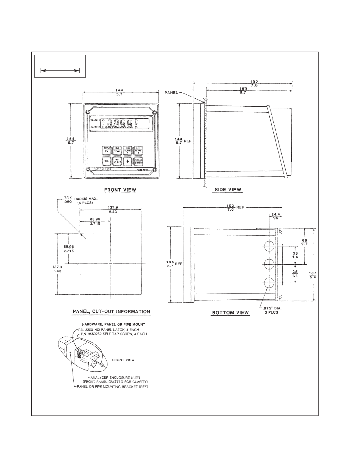
2.3.1 Panel Mounting (Standard). The Model 1054B
is designed to fit into a DIN standard 137.9 mm X
137.9 mm (5.43 in. X 5.43 in.) panel cutout (refer to
Figures 2-1 and 2-2).
1. Prepare the analyzer as described in Section 2.3.
2. Install the mounting latches as shown in Figure 22 (latches are shown oversize for clarity). If the
latches are not installed exactly as shown, they
will not work correctly. The screws provided are
self-tapping. Tap the screw the full depth of the
mounting latch (refer to side view) leaving a gap
greater than the thickness of the cutout panel.
3. Align the latches as shown and insert the analyzer enclosure through the front of the panel cutout.
Tighten the screws for a firm fit. To avoid damaging the mounting latches, do not use excessive
force.
4. Replace the front panel assembly. Circuit boards
must align with the slots on the inside of the enclosure. Replace the door and four front panel screws.
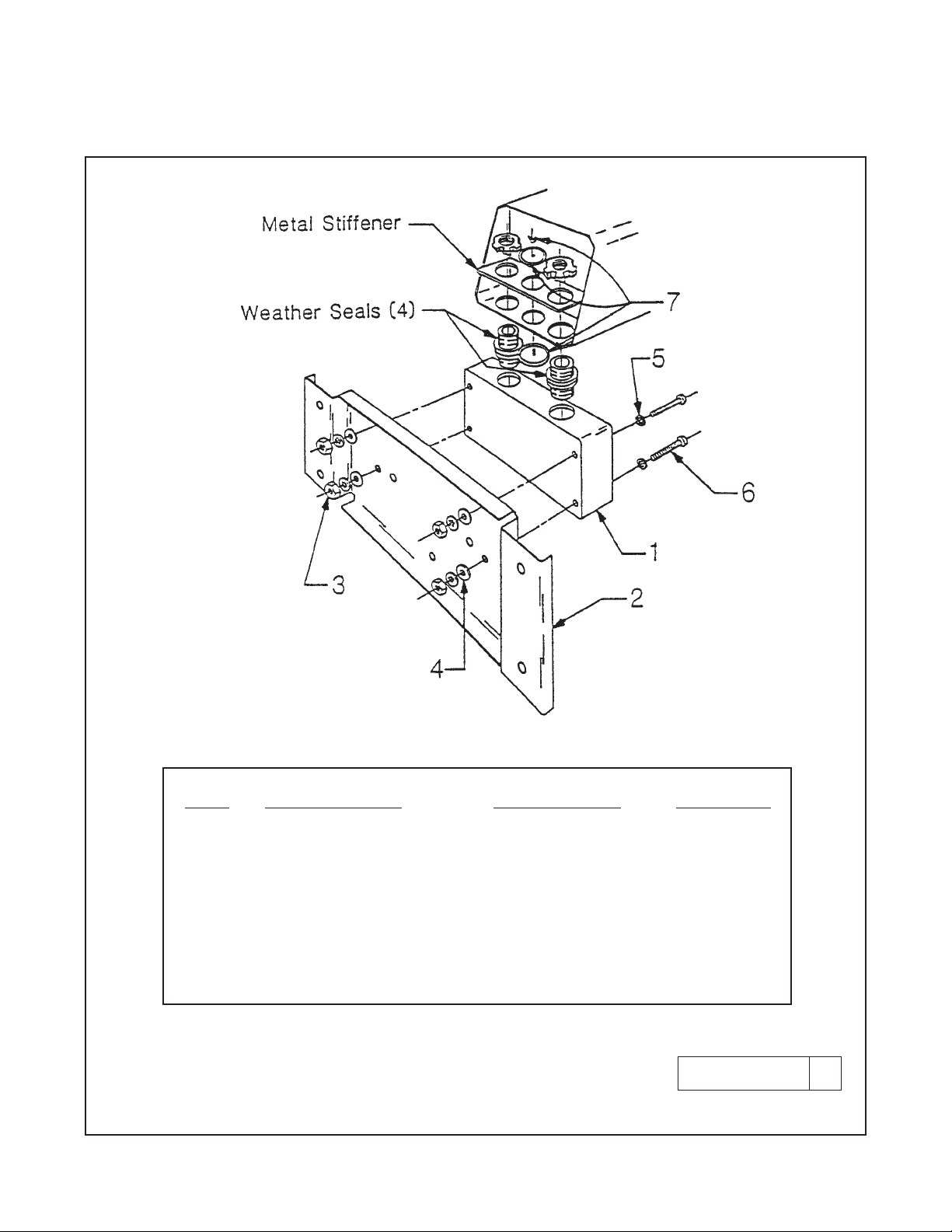
2.3.2 Wall Mounting (P/N 23054-01). Refer to
Figures 2-3 and 2-4. The integral preamp (P/N
23363-00) should not be used with this option.
1. Prepare the analyzer as described in Section 2.3.
2. Mount the junction box and bracket to the analyzer with the hardware provided. All wiring can be
brought to the terminal strip prior to mounting the
analyzer.
3. Place the metal stiffener on the inside of the analyzer and mount the two ¼-inch conduit fittings
using two each weather seals as shown. Mount
NEMA 4X conduit plug (included) into center conduit hole.
4. Mount the analyzer to the junction box using the
1/2-inch conduit fittings.
5. Complete wiring from the 1054B to the junction
box (Figure 2-4).
2.3.3 Pipe Mounting (P/N 23053-00). The 2-inch pipe
mounting bracket includes a metal plate with a cutout
for the 1054B refer to Section 2.3 for mounting the
analyzer into the plate. Mounting details are shown in
Figure 2-5.
2.3.4 Wall Mounting Enclosure (Option -20). Refer
to Figure 2-8. In this configuration, the analyzer is
housed in NEMA 4X heavy duty enclosure and may
be mounted on a wall or handrail. Sufficient clearance
should be provided in front of the enclosure to permit
opening the door, which is hinged on the left side.
Page 10

NOTE
The user must provide a means to disconnect the main power supply in the form of
circuit breaker or switch. The circuit breaker or the switch must be located in close
proximity to the instrument and identified
as the disconnecting device for the instrument.
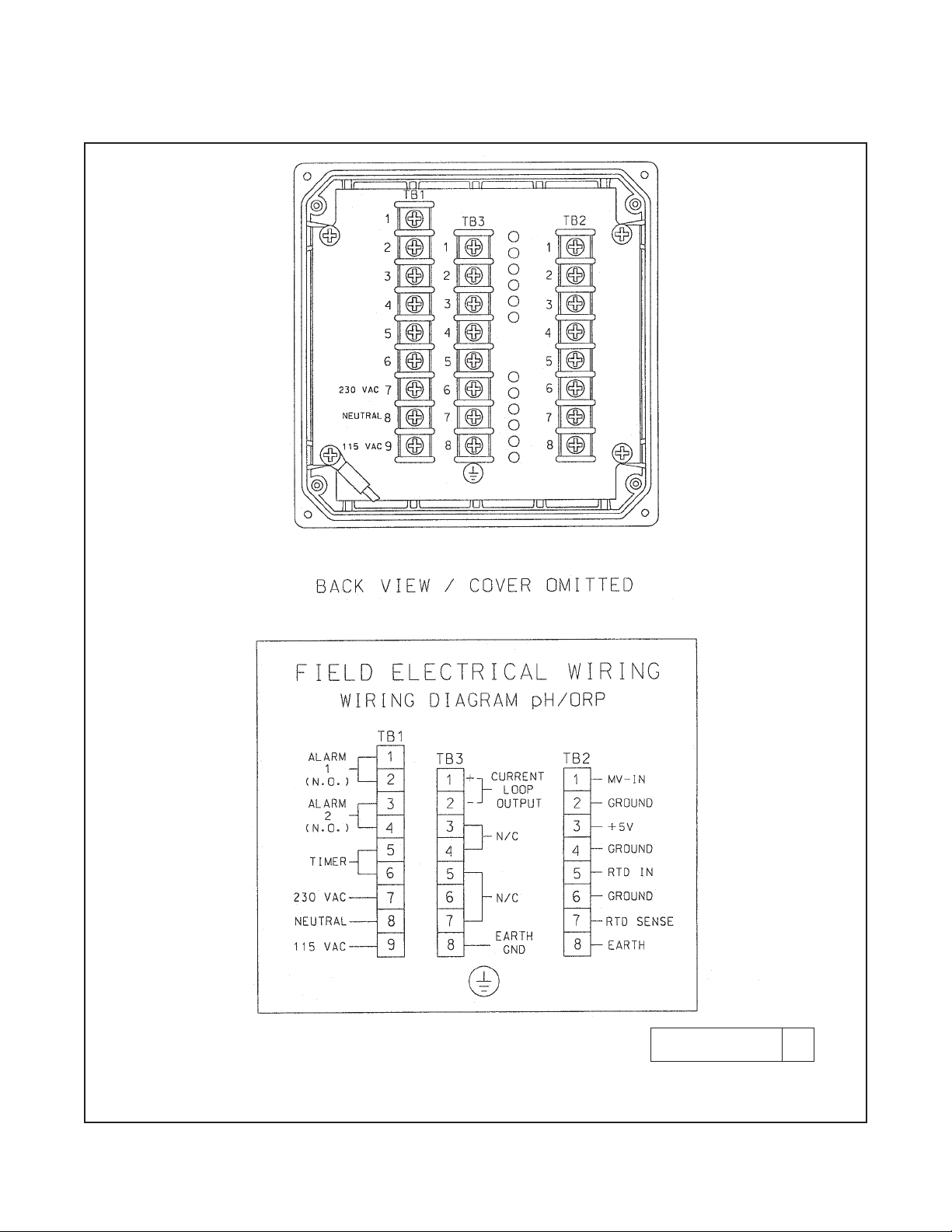
2.4.1 Power Input Wiring. The Model 1054B can be
configured for either 115 VAC or 230 VAC power.
Connect AC power to TB1-7 and -8 (230V), or TB1-8
and -9 (115 VAC) ground to the TB3-8 (refer to
Figure 2-6).
1. AC connections and grounding must be in compliance with UL 508 and/or local electrical codes.
2. The metal stiffener is required to provide support
and proper electrical continuity between conduit
fittings.
3. This type 4/4X enclosure requires a conduit hub
or equivalent that provides watertight connect,
REF UL 508-26.10.
4. Watertight fittings/hubs that comply with the
requirements of UL 514B are to be used.
5. Conduit hubs are to be connected to the conduit
before the hub is connected to the enclosure, REF
UL 508-26.10.
6. If the metal support plate is not used, plastic fittings must be used to prevent structural damage
to the enclosure. Also, appropriate grounding lug
and awg conductor must be used with the plastic
fittings.
2.4.2 Output Wiring. The signal output and alarm
connections are made to terminals 1 through 6 of TB1
and terminals 1 and 2 of TB3 (refer to Figure 2-6).
CAUTION
The sensitivity and stability of the analyzer
will be impaired if the input wiring is not
grounded. DO NOT apply power to the
analyzer until all electrical connections are
verified and secure. The following precautions are a guide using UL 508 as a safeguard for personnel and property.
4
MODEL 1054B pH/ORP SECTION 2.0
INSTALLATION
2.4 ELECTRICAL WIRING. The Model 1054B has
three conduit openings in the bottom rear of the
analyzer housing which will accommodate
1/2-inch
conduit fittings. From a back view, the conduit opening on the left is for timer, alarm, and AC connections; the center is for signal output and the opening
on the right is for sensor wiring. AC power wiring
should be 14 gauge or greater.
The wall mount enclosure has three 3/4-inch conduit
openings, two with 3/4-inch fittings and one with a
NEMA 4X conduit plug. From the front view the
conduit opening on the left is for sensor wiring; the
center is for signal output, and the right is for timer,
alarm and AC power supply connections. Sensor
wiring should always be run in a separate conduit
from power wiring.
NOTE
Wall mount: use opening on the left for sensor
wiring (refer to Figure 2-4 for wiring).
NOTE
PN 23363-00 (integral preamplifier). Refer to
Figure 2-7 for installation and wiring. PN 2350800 (integral preamp is for wall mount enclosure). Refer to Figure 2-9.
NOTE
For maximum EMI/RFI protection the output
cable should be shielded and enclosed in an
earth grounded, rigid metal conduit. When
wiring directly to the instrument connect the
output cable‘s outer shield to the transmitter’s
earth ground via terminal 8 on TB3, Fig. 2-6.
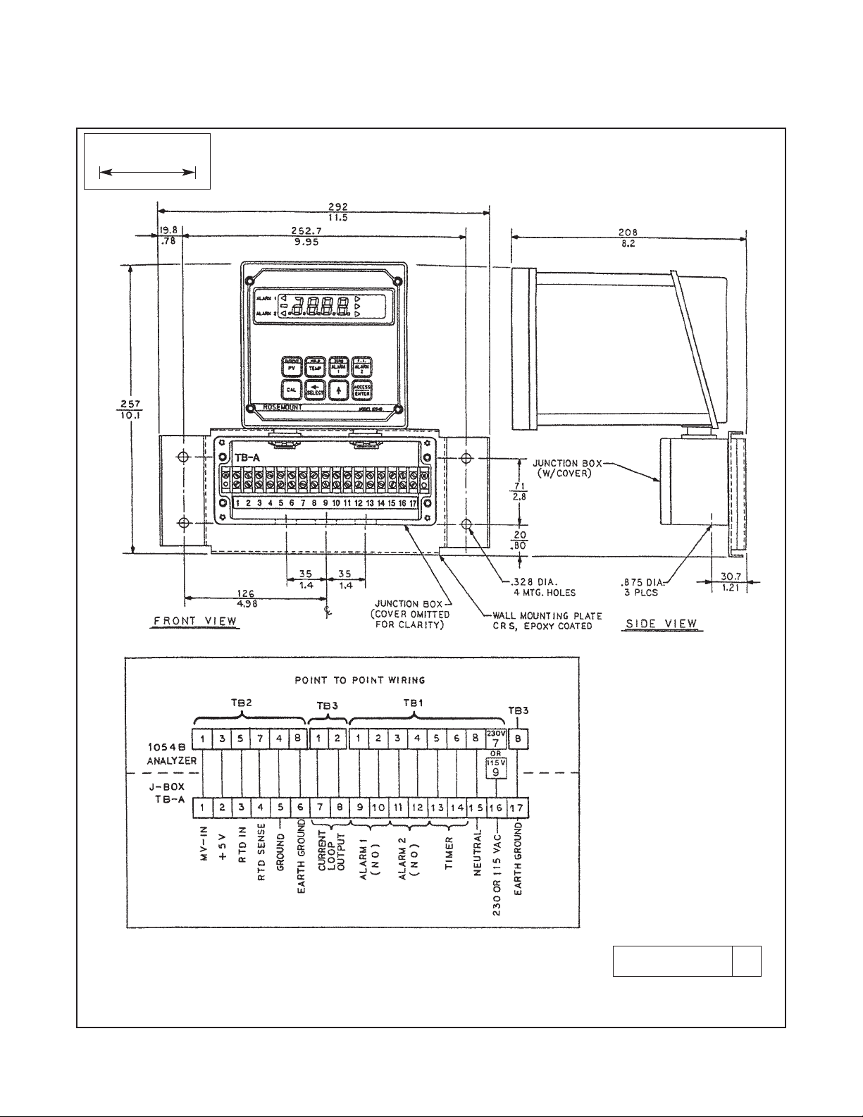
When wiring to the wall mounting junction box
connect the output cable’s outer shield to earth
ground via terminal 6 of TB-A, Fig. 2-4.
The sensor cable should also be shielded.
When wiring directly to the instrument connect
the sensor cable’s outer shield to the transmitter’s earth ground via terminal 8 of TB2, Fig. 2-
6. If the sensor cable’s outer shield is braid an
appropriate metal cable gland fitting may be
used to connect the braid to earth ground via
the instrument case. When wiring to the wall
mounting junction box connect the cable’s
outer shield to earth ground via terminal 6 of
TB-A, Fig. 2-4.
Page 11
5
FIGURE 2-1. Panel Mounting Cutout
MODEL 1054B pH/ORP SECTION 2.0
INSTALLATION
WHEN INCH AND METRIC DIMS
ARE GIVEN
MILLIMETER
INCH
DWG. NO. REV.
41054B01 B
Page 12

6
MODEL 1054B pH/ORP SECTION 2.0
INSTALLATION
FIGURE 2-2. Panel Mounting Tab Installation
DWG. NO. REV.
41054A26 A
Page 13
7
MODEL 1054B pH/ORP SECTION 2.0
INSTALLATION
FIGURE 2-3. Wall Mounting J-Box Installation
DWG. NO. REV.
41054A27 A
ITEM PART NUMBER DESCRIPTION QUANTITY
1 23058-01 S Assy, J-Box 1
2 33030-00 Bracket, wall mtg 1
3 9900600 Nut, 6-32 Hex 4
4 9910600 Washer, Flat #6 4
5 9910610 Washer, Lock Int. #6 8
6 9600612 Screw, 6-32 X .75 4
7 9510048 Seal, Weathertight 1
Page 14
MODEL 1054B pH/ORP SECTION 2.0
INSTALLATION
8
FIGURE 2-4. Wall Mounting J-Box Wiring
DWG. NO. REV.
41054B13 B
WHEN INCH AND METRIC DIMS
ARE GIVEN
MILLIMETER
INCH
Page 15

MODEL 1054B pH/ORP SECTION 2.0
INSTALLATION
9
FIGURE 2-5. Pipe Mounting Installation
WHEN INCH AND METRIC DIMS
ARE GIVEN
MILLIMETER
INCH
DWG. NO. REV.
41054B02 C
Page 16
10
MODEL 1054B pH/ORP SECTION 2.0
INSTALLATION
FIGURE 2-6. Electrical Wiring
DWG. NO. REV.
41054B03 C
Page 17

11
MODEL 1054B pH/ORP SECTION 2.0
INSTALLATION
FIGURE 2-7. Integral Preamp Wiring
DWG. NO. REV.
41054B32 B
Page 18

12
MODEL 1054B pH/ORP SECTION 2.0
INSTALLATION
FIGURE 2-8. Wall Mount Enclosure (Option -20)
DWG. NO. REV.
41054B43 A
WHEN INCH AND METRIC DIMS
ARE GIVEN
MILLIMETER
INCH
Page 19

13
MODEL 1054B pH/ORP SECTION 2.0
INSTALLATION
FIGURE 2-9. Integral Preamp Wiring for Group II Wall Mount Enclosure
DWG. NO. REV.
41054B44 A
MILLIMETER
INCH
Page 20

14
MODEL 1054B pH/ORP SECTION 3.0
DESCRIPTION OF CONTROLS
SECTION 3.0
DESCRIPTION OF CONTROLS
3.1 KEYBOARD FUNCTIONS.
All functions of the 1054B are accessed through keyboard entry routines. The analyzer uses no switches or
potentiometers.
The four keys across the top row and the CAL (pH only)
and ENTER keys are dual function. One press of the
key will display the value of the function shown on the
lower portion of the key. A quick double press of the key
will display the value of the function shown on the upper
portion of the key. Each of these keys have read functions that can be accessed without security code entry.
Each key also has a calibration or set function when
used with the SELECT key. This function requires entry
of the security code when the security feature is active.
(Refer to Section 6.0 for keyboard security.)
NOTE
When no key is pressed for a period of 60 seconds the analyzer will default to reading pH.
CAUTION
The HOLD function and the CAL function
are not read functions. Refer to Section 5.3.
A. Standardize pH/ORP. Standardization of the pH/ORP sensor is achieved
by pressing the PV key once, followed
immediately by pressing the SELECT
key. Std displays to acknowledge the
standardize function, followed by the
Numeric Display for user input. Entering
the known pH/ORP of the measured
solution will cause the analyzer to
restandardize the sensor. The pH glass
slope value will not be changed. Refer to
Section 5.4.
B. Standardize Temperature. Standardization of the temperature is achieved
by pressing the TEMP key once, followed
immediately by pressing the SELECT
key. AdJ displays to acknowledge the
standardization function, followed by the
Numeric Display for user input. Entering
the known temperature of the measured
solution will cause the analyzer to
restandardize the temperature reading.
Refer to Section 5.2.
C. Alarm 1 and Alarm 2 Setpoint. The
alarm setpoint may be adjusted by
pressing the ALARM 1 or ALARM 2 key
once, followed by pressing the SELECT
key. AdJ displays, followed by the
Numeric Display for user input. Refer to
Section 4.10.
D. Current Output – Zero Setpoint. The
zero point (0 or 4 mA) of the pH output
range is adjusted by pressing the ZERO
key twice, followed by pressing the
SELECT key. AdJ displays, followed by the
Numeric Display for user input. Refer to
Section 4.11.
E. Current Output – F.S. Setpoint. The
full scale point (20 mA) of the pH output
range is adjusted by pressing the F.S. key
twice, followed by pressing the SELECT
key. AdJ displays, followed by the
Numeric Display for user input. Refer to
Section 4.11.
F. Two Buffer Calibration (pH). A two
buffer calibration is initiated by pressing
the CAL key once. Refer to Section 5.3.
Calibration (ORP). A calibration is
initiated by pressing the CAL key once.
Refer to Section 5.3.
G. pH Glass Slope. The millivolt output
per pH unit is adjusted by pressing the
CAL key twice, followed by pressing the
SELECT key once. AdJ displays, followed
by the Numeric Display for user input.
Refer to Section 5.5.
H. Simulate Current Output. The pH
output can be simulated by pressing
the PV key twice, followed by pressing
the SELECT key. The Numeric Display
appears for user input. Refer to
Section 4.12.
ZERO
ALARM 1
OUTPUT
PV
HOLD
TEMP
CAL
ZERO
ALARM 1
F.S.
ALARM 1
OUTPUT
PV
CAL
Page 21

15
B. Scroll Key (é). This key is used to
scroll through menu when selected, or
scroll through digits on the active (flashing) Numeric Display. Holding key down
auto scrolls through the main menu and
Numeric display.
C. ACCESS/ENTER Key. This key is
used to ACCESS the Set Mode (Section
4.1.2) and to ENTER the displayed value
into memory (from Numeric Display).
é
3.1.1 Item Selection and Value Adjustment Keys.
The three keys located on the lower right side of the
keypad are used for menu navigation, value adjustment and entry, and item selection. These keys perform the following functions:
A. SELECT/Shift (ç) Key. This key is
used to select the displayed menu, or for
shifting to the next digit in the Numeric
Display.
MODEL 1054B pH/ORP SECTION 3.0
DESCRIPTION OF CONTROLS
ç
SELECT
ACCESS
ENTER
FIGURE 3-1. LCD DISPLAY
RELAY 1
ACTIVATED
RELAY 2
ACTIVATED
pH VALUE:
FLAG ON
mV VALUEFLAG BLINKING
(ORP FLAG ON)
% VALUE FLAG ON
mA VALUEFLAG BLINKING
HOLD STATUS
FLAG ON
FAULT FLAG BLINKING
UPPER FUNCTION PRESS
TWICE
QUICKLY
LOWER FUNCTION PRESS
ONCE
Page 22

16
MODEL 1054B pH/ORP SECTION 3.0
DESCRIPTION OF CONTROLS
TABLE 3-1. Key Description
Displays - current output (mA or % full
scale).
Set Function (w/SELECT) - Simulates
current output.
Displays - low current setpoint (0 or 4 mA value).
Set Function (w/SELECT) - Sets low current point
(0 or 4 mA value).
Displays - full scale output setpoint.
Set Function (w/SELECT) - Sets full
scale output point.
Select sub menu (mnemonic display).
Shift to next digit (numeric display).
Scroll through menu (mnemonic display).
Scroll digits (numeric display).
Holding key down autoscrolls digits
or set menu items.
Press twice to access set-up menu.
Enter displayed value into memory.
Enter displayed menu item (flashing) into memory.
Two Point Calibration (pH).
Calibration (ORP).
Displays - Alarm 1 setpoint.
Set Function (w/SELECT) - Sets Alarm 1
setpoint.
Displays - pH/ORP.
Set Function (w/SELECT) - One point
standardization of pH/ORP.
PV= Primary Variable
Initiates or removes analyzer from hold
condition.
Displays - process temperature (°C or
°F).
Set Function (w/SELECT) - One point
standardization of temperature.
Displays - Alarm 2 setpoint.
Set Function (w/SELECT) - Sets Alarm 1
setpoint.
ACCESS
ENTER
Displays - pH glass slope (efficiency).
Set Function (w/SELECT) - manually
sets pH glass slope (efficiency).
SECOND FUNCTION (PRESS TWICE QUICKLY)
MAIN FUNCTION (PRESS ONCE)
CAL
F.S.
ALARM
2
ZERO
ALARM
1
HOLD
TEMP
OUTPUT
PV
ç
SELECT
é
Page 23

17
MODEL 1054B pH/ORP SECTION 3.0
DESCRIPTION OF CONTROLS
MNEMONIC DESCRIPTION
Ab1 Automatic Buffer 1
Ab2 Automatic Buffer 2
AdJ Adjustment to value reading
bAd Incorrect entry
bF1 Buffer 1
bF2 Buffer 2
doc Displays output current in mA
HLd Analyzer in hold mode
HI Displays 20 mA setpoint (pH/ORP)
itr Interval timer activated
LO Displays 0 or 4 mA setpoint (pH/ORP)
MNEMONIC DESCRIPTION
LOC Access locked - enter security code
Pct Displays pH/ORP output in percent
PH pH Display
OrP ORP Display
SEt Set mode
SiP Simulates current output (percent)
SC1 Simulates current output (mA)
SLP Displays pH electrode slope
SP1 Displays alarm 1 setpoint
SP2 Displays alarm 2 setpoint
Std Standardize pH/ORP
AbF Auto buffer mode
AL1 Alarm 1 setup
AL2 Alarm 2 setup
Atc Automatic temp. comp.
DC Temperature °C
CAL Calibration impedance
setpoint
COd Security Code
cnt Timer count
CUr Config. current output
Cur Config. fault output
cur Default current setpoint
dAY Days
dFt Fault Configuration
d-O Display output
d-t Display temperature
diS Display Convention
doc Display output in mA
doF Relay delay off time
don Relay delay on time
dPn Dampen output
dtS LCD/LED Display test
dur Timer duration
Ein Display mV input
DF Temperature °F
FLt Use alarm as fault alarm
Hi Relay action - high
H-L Alarm logic
hr Hours
HYS Hysteresis
int Interval period
Int Timer setup
iPH Isopotential pH
iSO Isopotential point
Lo Relay action - low
non No action on fault
OFF Alarm not used
ont Timer on time
oFF Relay open on fault
On Use alarm as process alarm
OFt Timer off time
OId
Old electrode impedance limit
Or U.S. Convention
OUt Current output
Pct Display output in percent
rL1 Relay 1 fault setup
rL2 Relay 2 fault setup
rES Impedance value
rPH Normal process pH
rO European Convention
SEC Seconds
SHt
Cracked glass impedance limit
SHO Show fault history
t-C Temperature config.
tCO Temperature coefficient
tiL Timer - time remaining
tOn Timer status
UEr User version
uin Minutes
420 4mA to 20mA output
020 0mA to 20mA output
TABLE 3-3. Set Function Mnemonics
TABLE 3-2. Information Mnemonics
Page 24

18
MODEL 1054B pH/ORP SECTION 4.0
CONFIGURATION
SECTION 4.0
CONFIGURATION
4.1 CONFIGURATION. This section details all of the
items available in the Set Mode to configure the
analyzer to a specific application.
4.1.1 Configuration Work Sheet. The configuration
work sheet on page 20 (or, in the case of ORP, the
worksheet on page 22) should be filled out before proceeding with the analyzer's configuration. This sheet
gives a brief parameter description, the factory setting, and a space for user setting.
4.1.2 Set Mode. Display mnemonic SEt. Most of the
analyzer's configuration is done while in the Set
Mode. Please refer to Figure 4-1 for the layout of all
menu items for pH measurement. Refer to Figure 4-2
for the layout of all menu items for ORP measurement. All menu variables are written to the analyzer's
EEPROM (memory) when selected and remain there
until changed. As these variables remain in memory
even after the analyzer's power is removed, the Model
1054B pH/ORP configuration may be performed prior
to installing it.
1. Power up the analyzer. Only power input wiring is
required for analyzer configuration (Refer to
Section 2.4.1). The analyzer's display will begin
showing values and/or fault mnemonics. All fault
mnemonics will be suppressed while the analyzer
is in Set Mode (the fault flag will continue to
blink).
2. Enter Set Mode. Pressing the ACCESS key twice
in rapid succession will place the analyzer in Set
Mode. The display will show SEt to confirm that it
is in Set Mode. It will then display the first item in
the Set Menu Ein. The analyzer is now ready for
user configuration.
NOTE
If LOC displays, the Keyboard Security
Code must be entered to access the Set
Mode. (Refer to Section 6.0.)
3. Analyzer variables can be entered in any order.
On initial configuration, however, it is recommended that the variables be entered in the order
shown on the work sheet (page 20 - pH, page 22
- ORP). This will reduce the chance of accidentally omitting a needed variable.
Page 25

19
FIGURE 4-1. Menu Items (pH)
MODEL 1054B pH/ORP SECTION 4.0
CONFIGURATION
H-L
HYS
don
doF
On
OFF
Ein
AL1
AL2
Int
t-C
OUt
InP
iSO
dFt
AbF
UEr
dtS
COd
SEt
Hi
Lo
tOn
int
cnt
ont
OFt
dur
tiL
oFF
on
SEC
uin
hr
dAY
°F
o
C
doc
Pct
on
oFF
non
non
cur
rL1
rL2
Cur
SHO
on
oFF
On
FLt
OFF
420
020
d-t
Atc
dPn
CUr
d-O
rPH
iPH
tCO
on
oFF
on
oFF
rES
CAL
SHt
OId
Page 26

20
MODEL 1054B pH/ORP SECTION 4.0
CONFIGURATION
TABLE 4-1. Configuration Work Sheet (pH)
Use this work sheet to assist in the configuration of the analyzer. Date: ____________________
RANGE FACTORY SET USER SET
A. Alarm 1 Setup (AL1)
1. Alarm Configuration (On/OFF) On _________
2. High or Low (H-L) (Hi/Lo) Lo _________
3. Hysteresis (HYS) 0-2.0 pH 0 pH _________
4. Delay Time On (don) 0-255 sec. 000 Seconds _________
5. Delay Time Off (doF) 0-255 sec. 000 Seconds _________
B. Alarm 2 Setup (AL2)
1. Alarm Configuration (On/FLt/OFF) On _________
2. High or Low (H-L) (Hi/Lo) Hi _________
3. Hysteresis (HYS) 0-2.0 pH 0 pH _________
4. Delay Time On (don) 0-255 sec 000 Seconds _________
5. Delay Time Off (doF) 0-255 sec 000 Seconds _________
C. Interval Timer (
IInntt
)
1. Active Status (tOn) (oFF/on) oFF _________
2. Interval Time (int) Minimum 10 Minutes 10 Seconds _________
3. Count (cnt) 1 to 60 5 _________
4. On Time (ont) 0 to 299 sec 1 Second _________
5. Off Time (OFt) 0 to 299 sec 1 Second _________
6. Duration (dur) 0 to 299 sec 2 Seconds _________
D. Temperature Setup (t-C)
1. Display Temperature (d-t) (oC/oF) *C _________
2. Automatic Temperature
Compensation (Atc) (on/oFF) on _________
a. Manual Temp. Value -10°C to 125°C _________
E. Current Output Setup (OUt)
1. mA Output (CUr) (020/420) 420 _________
2. Display Current Output (d-O) (Pct/doc) doc _________
3. Dampen Current Output (dPn) 0-255 sec. 0.0 Seconds _________
F. Electrode Diagnostics Setup (InP) (on/oFF) oFF
1. Temp compensated impedance (rES)
2.
Impedance increase before calibration
(CAL) 20-200% 20% _________
3. Cracked glass impedance low limit (SHt) 5-600 megohms 20 megohms _________
4. Aged electrode impedance high limit (OId)
200-1999 megohms
1000 megohms _________
G. Default Setup (dFt)
1. Relay 1 Default (rL1) (non/oFF/on) non _________
2. Relay 2 Default (rL2) (non/oFF/on) non _________
3. Current Output Default (Cur) (non/cur) non _________
H. Automatic Buffer Mode (AbF)
1. Configuration (on/off) on _________
I. Keyboard Security Setup (COd)
1. Keyboard Security Required 001-999
_
_________
2. Keyboard Security Not Required 000 000 _________
Alarm Setpoints
1. Alarm 1 (SP 1) 0-14 pH 0.00 pH _________
2. Alarm 2 (SP 2) 0-14 pH 14.00 pH _________
Current Output
1. Zero (0 or 4 mA) (LO) 0-14 pH 0.00 pH _________
2. F.S. (20 mA) (HI) 0-14 pH 14.00 pH _________
Page 27

21
MODEL 1054B pH/ORP SECTION 4.0
CONFIGURATION
SEt
On
OFF
Hi
Lo
oFF
on
SEC
uin
hr
dAY
On
FLt
OFF
H-L
HYS
don
doF
d-t
Atc
°F
°C
tOn
int
Cnt
Ont
OFt
dur
tiL
on
oFF
dPn
CUr
d-O
Or
rO
rL1
rL2
Cur
SHO
420
020
non
cur
on
oFF
non
doc
Pct
AL1
AL2
Int
t-C
OUt
d1S
dFt
UEr
dtS
COd
FIGURE 4-2. Set Function Menu (ORP)
Page 28

22
MODEL 1054B pH/ORP SECTION 4.0
CONFIGURATION
RANGE FACTORY SET USER SET
A. Alarm 1 Setup (AL1)
1. Alarm Status (On/OFF) On _________
2. High or Low (H-L)(Hi/Lo) Lo _________
3. Hysteresis (HYS) 0-25% of setpoint 0.0% _________
4. Delay Time On (don) 0-255 sec. 000 Seconds _________
5. Delay Time Off (doF) 0-255 sec. 000 Seconds _________
B. Alarm 2 Setup (AL2)
1. Alarm Status (On/ FLt/ OFF) On _________
2. High or Low (H-L)(Hi/Lo) Hi _________
3. Hysteresis (HYS) 0-25% of setpoint 0.0% _________
4. Delay Time On (don) 0-255 sec. 000 Seconds _________
5. Delay Time Off (doF) 0-255 sec. 000 Seconds _________
C. Interval Timer (Int)
1. Active Status (tOn)(oFF/on) oFF _________
2. Interval Time (int) minimum 10 minutes 1 Day _________
3. Count (Cnt) 1 to 60 5 _________
4. On Time (Ont) 0 to 299.9 sec 1 Second _________
5. Off Time (OFt) 0 to 299.9 sec 1 Second _________
6. Duration (dur) 0 to 299.9 sec 2 Seconds _________
D. Temperature Setup (t-c)
1. Display Temperature (d-t)(oC/oF) °C _________
2. Automatic (t-C)(Atc)(on/ oFF) On _________
E. Current Output Setup ((OUt)
1. mA Output (CUr)(020/ 420) 420 _________
2. Display Current Output (d-O)(Pct/ doc) doc _________
3. Dampen Current Output (dPn) 0-255 sec. 0.0 Seconds _________
F. Displays Convention
1. U.S. (Or)/European (rO) Or __________
G. Default Setup (dFt)
1. Relay 1 Default (rL1)(non/ oFF/on) non _________
2. Relay 2 Default (rL2)(non/ oFF/on) non _________
3. Current Output Default (Cur)(non/ cur) non _________
H. Keyboard Security Setup
1. Keyboard Security Required 001-999 _ _________
2. Keyboard Security Not Required 000 000 _________
Alarm Set Points
1. Alarm 1 (SP1) -1500 - +1500 mV -1500 mV _________
2. Alarm 2 (SP2) -1500 - +1500 mV +1500 mV _________
Current Output
1. Zero (0 or 4 mA) -1500 - +1500 mV -1500 mV _________
2. F.S. (20 mA) -1500 - +1500 mV +1500 mV _________
TABLE 4-2. Configuration Worksheet (ORP)
Use this work sheet to assist in the configuration of the analyzer. Date: ____________________
Page 29

23
MODEL 1054B pH/ORP SECTION 4.0
CONFIGURATION
4.2 ALARM 1 AND 2. Display Mnemonic AL1 or AL2.
Used to set alarm relay logic. The alarms may be configured to perform on-off process control. See note
below.
A. On. Display Mnemonic On. Select this item if Alarm
1 or 2 is to be used as a process alarm. See Steps D
thru G for further alarm configuration.
B. Off. Display Mnemonic OFF. Select this item if Alarm
1 or 2 will not be used as a process alarm or to temporarily disable either alarm. Alarm 1 or 2 setpoint will
display oFF if this item is selected. Omit Steps C thru G.
C. Fault (Alarm 2 Only). Display Mnemonic FLt.
Select to make Alarm 2 energized when the analyzer
detects a fault condition. See Table 8-1 for a listing of
the fault mnemonics and their descriptions. Alarm 2
setpoint will display FLt if this item is selected. Omit
Steps D thru G.
D. Alarm Logic. Display Mnemonic H-L. Select this
item for high or low alarm logic. High logic activates the
alarm when the reading is greater than the set point
value. Low logic activates the alarm when the reading
is less than the setpoint value.
E. Relay Hysteresis. Display Mnemonic HYS. Sets the
relay hysteresis (dead band) for deactivation after
reading has passed the alarm setpoint. May be set
from 0 to 2.0 pH. Use hysteresis when a specific pH
should be reached before alarm deactivation.
F. Delay Time On. Display Mnemonic don. Sets time
delay for relay activation after alarm setpoint is
reached. May be set from 0 to 255 seconds.
G. Delay Time Off. Display Mnemonic doF. Sets time
delay for relay deactivation after alarm setpoint is
reached. May be set from 0 to 255 seconds. Alarm
state restarts time from zero. Use when a fixed time
should pass before relay deactivation occurs.
4.2.1 Alarm Setup (AL1/AL2).
1. Enter Set Mode by pressing ACCESS key twice.
2. SCROLL (é) until AL1 or AL2 appears on the display.
3. SELECT to move to the next menu level. On, OFF
or (AL2 only) FLt will display.
4. SCROLL (é) to display desired item then
SELECT.
5. If OFF is selected, display will show oFF to
acknowledge. Press ENTER key to return to AL1
or AL2, concluding routine. Skip to Step 11.
If On is selected, display will show on to acknowledge, then display H-L. Proceed to Step 6.
If FLt is selected, display will show FLt to
acknowledge. Press ENTER key to return to AL2.
6. SELECT H-L. Hi or Lo will display (flashing).
7. SCROLL (é) to the desired item and ENTER it
into memory. Display will return to H-L. If changes
to relay activation logic are desired, proceed to
Step 8, otherwise Step 12.
8. SCROLL (é) to display HYS, don or doF, then
SELECT desired item. The Numeric Display will
flash to indicate that a value is required.
9. Use SCROLL (é) and SHIFT (ç) to display the
desired value.
10. ENTER value into memory. Analyzer will
acknowledge and return to display of last item
selected. Repeat Step 8 if further changes are
desired, otherwise Step 12.
11. Repeat Step 3 for the other Alarm’s settings as
required.
12. To return to the first level of the Set Mode, press
the ACCESS key.
Page 30

24
MODEL 1054B pH/ORP SECTION 4.0
CONFIGURATION
4.3.1 Interval Timer Set Up (Int).
1. Enter Set Mode by pressing ACCESS key twice.
2. SCROLL (é) until Int appears on the display.
3. SELECT to move to the next menu level. tOn will
display.
4. SCROLL (é) to display on or oFF and ENTER it
into memory. If interval configuration is required,
proceed to Step 5, otherwise Step 10.
5. SCROLL (é) to display desired menu item. If int
is selected, proceed to Step 6, otherwise Step
10.
6. SCROLL (é) to display desired interval period
and SELECT. The Numeric Display will flash.
7. SCROLL (é) and SHIFT (ç) to display the
desired value and ENTER it into memory. Display
will return to interval period menu.
8. Repeat Steps 6 and 7 as needed.
9. Press the ENTER key to return to the main timer
menu.
10. SELECT the desired item. The Numeric Display
will flash.
11. SCROLL (é) and SHIFT (ç) to display the
desired value and ENTER it into memory.
12. Repeat Steps 5, 10, and 11 as required.
13. Press the ENTER key to return to the Set Menu.
4.3 INTERVAL TIMER. Display Mnemonic Int. This
item is used to set the interval timer's relay logic. The
timer can be used for sensor maintenance, such as
wash cycle or ultrasonic cleaner activation. Refer to
Figure 4-3.
A. Interval Timer Enable/Disable. Display
Mnemonic tOn. Select this item to begin interval cycle
on or disable interval cycle oFF.
B. Interval Period. Display Mnemonic int. Select this
item to set the time period between control cycles. SEC
for seconds, uin for minutes, hr for hours, and dAY for
days. May be set from a minimum of 10 minutes.
C. Relay Activations Per Cycle. Display Mnemonic
cnt. Select this item to enter the number of times the
relay will activate per cycle. May be set from 1 to 60.
D. Relay Activation Duration. Display Mnemonic
ont. Select this item to enter the relay activation time
for each cnt. May be set from 0 to 299 seconds.
E. Relay Deactivation Duration. Display Mnemonic
OFt. Select this item to enter the relay deactivation
time between each cnt during the control cycle. Valid
when cnt is 2 or greater. May be set from 0 to 299
seconds.
F. Wait Duration. Display Mnemonic dur. Select this
option to enter the electrode recovery time after the
last cnt in a cycle. May be set from 0 to 299 seconds.
The duration can be used for electrode recovery after
a wash cycle.
G. Interval Time Remaining. Display Mnemonic tiL.
Select this item to display the time remaining until the
next control cycle. If selected during the control cycle,
the display will show ---.
NOTE
The Model 1054B pH is placed on hold
during the control cycle (from first relay
activation through the wait duration).
The analyzer will simulate a fault condition and briefly show itr every eight
seconds. The display will continue to
show the measured value.
RELAY
ACTIVATION
TIME
int
ont
dur
cnt = 1
0Ft = 0
One Wash Cycle
FIGURE 4-3. Interval Timer Example
Page 31

25
MODEL 1054B pH/ORP SECTION 4.0
CONFIGURATION
4.4 TEMPERATURE. Display Mnemonic t-C. Select
this item for temperature reading and compensation
choices.
A. Temperature Display. Display Mnemonic d-t.
Select this item to toggle between °F and °C temperature display. The 1054B will show all temperatures in
units selected until the selection is changed.
B. Automatic Temperature Compensation (pH
only). Display Mnemonic Atc. The Model 1054B pH
will use the temperature input from the sensor for
temperature compensation when on is selected. When
oFF is selected, the analyzer will use the value entered
by the user for temperature compensation. This manual temperature option is useful if the temperature sensor is faulty or not on line. Temperature specific faults
(tcH and tcL) will be disabled (Refer to Table 8-1).
4.4.1 Temperature Setup (t-C).
1. Enter Set Mode by pressing ACCESS key twice.
2. SCROLL (é) until t-C appears on the display.
3. SELECT to move to the next menu level. d-t will
display.
4. SCROLL (é) to display desired item, then
SELECT.
5. If d-t is selected, display will show oC or oF.
If Atc is selected, display will show on or oFF.
6. SCROLL (é) then ENTER desired item into
memory.
7. If oC, oF, or on are entered, display will return to
the previous level (proceed to Step 9).
If oFF is selected, the Numeric Display will flash
indicating that a process temperature value is
required (proceed to Step 8).
8. Use SCROLL (é) and SHIFT (ç) to display the
desired value. ENTER value into memory.
9. Repeat Steps 4-8 as required for other item.
10. Press the ENTER key to return to Set Menu.
4.5 CURRENT OUTPUT. Display Mnemonic OUt. This
item is used to configure the current output signal.
A. Output Dampening. Display Mnemonic dPn.
Dampens the response of the signal output. This
option is useful to minimize the effect of a noisy reading. The number entered is the sample time (in seconds) for an averaged output. Zero to 255 seconds
may be entered.
B. mA Output Range. Display Mnemonic CUr.
Selection of this item will allow choice of 0 to 20 mA or
4 to 20 mA output range.
C. Display Output. Display Mnemonic d-O. This item
is used to select logic of output display. Selecting this
item will allow the 1054B pH to display current output
as mA doc or as a percent of full scale output range
Pct.
4.5.1 Output Setup (OUt).
1. Enter Set Mode by pressing the ACCESS key
twice .
2. SCROLL (é) until OUt appears on the display.
3. SELECT to move to the next menu level. dPn will
display.
4. SCROLL (é) then SELECT desired item.
5. If dPn is selected, the Numeric Display will flash
indicating that a value is required. Proceed to
Step 6.
If CUr or d-O is selected, proceed to Step 7.
6. SCROLL (é) then SHIFT (ç) to display the
desired value. ENTER into memory.
7. SCROLL (é) then ENTER desired item.
8. Repeat Steps 4-7 as required.
9. Press the ENTER key to return to the Set Menu.
Page 32

26
MODEL 1054B pH/ORP SECTION 4.0
CONFIGURATION
4.6 pH ELECTRODE DIAGNOSTICS (1054B pH
only). Display Mnemonic InP. Under this item are func-
tions associated with glass electrode diagnostics. These
diagnostics are possible through a continuous, temperature compensated measurement of the sensor impedance (resistance), rES, made from the preamp. A soft-
ware selectable on setting will activate these diagnostics. If oFF is the setting (factory setting) these
diagnostics will all be disabled.
A new electrode has an impedance of approximately
200 megohms, and as it ages the impedance increases because lithium ions (which carry current) in the
glass slowly get depleted by the process. If an electrode cracks, the impedance drops sharply, usually to
below 70% of the normal value.
The following are typical impedance values for new
Rosemount Analytical electrodes (Electrodes stored
over a period of time will have higher impedances). Upon
installation you can read impedance in megohms under
rES.
Sensor/Glass Megohms @
Type
30°C (86°F) when new
• General purpose, 30-100
HF, and high pH glass (GPLR)
• General Purpose
High Temp (GPHT) 50-90
• Ruggedized glass 200-300
For more information on these diagnostics and troubleshooting, refer to Section 8.0.
NOTE
Impedance diagnostic faults are not activated until the setpoint is continuously
exceeded for 30 seconds.
A. Calibration Warning. Display Mnemonic CAL.
Under this mnemonic you can select the percent
increase in impedance before a calibration warning
fault appears. For example, if the impedance is 400
megohms and the setpoint is 20% (factory setting), a
CAL warning will appear on the analyzer and it will go
into a fault mode when the electrode ages to 480
megohms. This diagnostic will reset after a buffer calibration. Configurable range: 20-200%. A setting of
zero disables this fault.
NOTE
The recommended process temperature
range for the CAL diagnostic is 15-90°C
(15-194°F.) (For low impedance glass it is
15-80°C (59-176°F). If ruggedized glass is
used and the preamp is not in the sensor,
the minimum recommended temperature
is 35°C (95°F).
If you want to use this feature as a warning yet not
upset your process, use Alarm 2 as a fault alarm (Refer
to Section 4.2) and set the default current output to non
(Refer to Section 4.8) to hold the output at the last
process value.
You may also get this fault if:
1. The electrode or junction becomes excessively
coated.
2. The electrode is not immersed in the process fluid.
If the electrode continues to remain out of solution
eventually the fault mnemonic OId will also appear
on the display. See part C.
B. Cracked Glass Diagnostic. Display Mnemonic SHt.
One way to tell that you have a broken or cracked glass
electrode is that the analyzer will read a constant value
(usually between 5.0-7.0 pH) in any process or buffer.
The other way is to note the impedance value. When a
crack occurs the mnemonic SHt will appear on the analyzer to indicate that the circuit is shorted, and the analyzer will go into a fault mode. Directions for SHt value
determination:
SHt ~ 70% of normal rES
Configurable range: 5-600 megohms. A setting of zero
disables this fault. Factory setting: 20 megohms.
NOTE
For low impedance glass, a broken electrode may not be detectable above 7075°C (158-167°F).
C. Worn Out Electrode. Display Mnemonic OId. This
mnemonic is used for programming the high impedance limit of the electrode. For example, if the setpoint
is 1000 megohms (factory setting), and the impedance
rises above this value, the mnemonic OId will appear
on the analyzer and it will go into a fault mode. The
electrode is either worn out, severely coated, or not
immersed in the process fluid. Configurable range:
200-1999 megohms. A setting of zero disables this
fault.
Recommended setpoints:
1. 1000 megohms for all glass except ruggedized
2. 1300 meghoms for ruggedized glass
Page 33

MODEL 1054B pH/ORP SECTION 4.0
CONFIGURATION
4.6.1 pH Electrode Diagnostics Setup
1. Enter the Set Menu by pressing the ACCESS key
twice.
2. SCROLL (é) until InP appears on the display and
SELECT.
3. on or oFF will display. If necessary, SCROLL (é) to
the desired mnemonic then ENTER. on activates
the diagnostics features.
4. If oFF is entered you can press the ENTER key to
return to the main set menu or press the pH key to
read pH.
If on is entered, the display will show rES. Proceed
to Step 5.
5. SCROLL (é) to display rES, CAL, SHt, or OId, then
SELECT the desired item. rES is a read only function. If CAL, SHt, or OId is selected, the right most
digit of the Numeric Display will flash to indicate
that the value can be changed.
6. Use the SCROLL (é) and SHIFT (ç) keys to
change the value, if desired.
7. ENTER the value into memory.
8. Press ENTER to return to the main Set Menu.
4.7 SOLUTION TEMPERATURE COMPENSATION
AND ISOPOTENTIAL POINT (Model 1054B pH
only). Display Mnemonic iSO. Used for applications
where the process' isopotential point (iPH) and temperature coefficient (tCO) are not standard. For normal pH
measurements these values should be: rPH = 7.00
(normal process pH), iPH = 7.00 pH, tCO = 0.00 pH/°C.
These values should only be changed for special applications.
Solution temperature compensation is designed to
correct for changes in the actual pH of a solution
caused by changes in dissociation with temperature.
During standardization (Section 5.4), if the sample pH
is greater than about 6.5 and the lab test is run at a
substantially different temperature than the process,
determine a value for tCO in pH/°C and enter that
value. The tCO should be determined over as narrow a
temperature operating range as possible.
The isopotential point is the pH value at which temperature changes do not affect the pH reading.
The analyzer method requires the user to enter the
normal process pH (rPH) and the temperature coefficient (tCO), then the isopotential point (iPH) will be calculated. Conversely, entering the normal process pH
and the isopotential point causes the temperature
coefficient to be calculated.
4.7.1 pH Measurement in High Purity Water with
Ammonia Present. The special characteristics of this
measurement require changing isopotential pH value
and temperature coefficient used by the Model 1054B
pH. The reference pH (rPH) is the user’s normal
process pH. The isopotential pH value (iPH) of high
purity water with ammonia is 16.84 pH. The temperature coefficient tCO is – 0.033 pH/°C.
4.7.2 Isopotential Point Set Up (iSO).
1. Enter Set Mode by pressing the ACCESS key
twice.
2. SCROLL (é) to display iSO and SELECT.
3. SCROLL (é) to the desired menu item and
SELECT. The Numeric Display will flash.
4. SCROLL (é) and SHIFT (ç) to display the
desired value and ENTER it into memory.
5. Repeat Steps 3 and 4 as required.
6. Press the ENTER key to return to the Set Menu.
27
Page 34

28
MODEL 1054B pH/ORP SECTION 4.0
CONFIGURATION
4.8 DEFAULTS. Display Mnemonic dFt. This item is
used to set the configuration of relays and output
default conditions during fault or hold status. See
Table 8-1 for a listing of the possible fault conditions
which can be diagnosed by the analyzer.
A. Relay 1 and 2. Display Mnemonic rL1 and rL2.
During a fault or hold condition the relays can be set
to activate on, deactivate oFF, or remain in the state
determined by the last process value non. See Table
4-3.
B. Current Output. Display Mnemonic Cur. The cur-
rent output is held at the last process value non or
goes to a specified value in mA cur during a fault or
hold condition.
C. Fault History. Display Mnemonic SHO. SELECT this
item will sequence the display through all faults
detected in most recent fault mode. Press the
SCROLL (é) key once for previous fault mode list.
Pressing ACCESS will clear SHO history.
4.8.1 Default Setup (dFt).
1. Enter Set Mode by pressing the ACCESS key
twice.
2. SCROLL (é) until dFt appears on the display.
3. SELECT to move to the next menu level. rL1 will
display.
4. SCROLL (é) then SELECT desired item.
5. Display will show next item selection. SCROLL
(é) and ENTER desired item.
6. Repeat Steps 4 and 5 as required for other
default settings rL2 and Cur. If cur is selected for
Cur, press ENTER, then use the SCROLL (é)
and SHIFT (ç) keys to enter the desired current
value for a fault or hold condition.
7. Press the ENTER key to return to Set Menu.
ANALYZER CONDITION
NORMAL HOLD FAULT
Set men AL1/AL2 setting Set menu AL1/AL2 setting Set menu AL1/AL2 setting
On OFF FLt On OFF FLt On OFF FLt
(Alarm 2 (Alarm 2 (Alarm 2
only) only) only)
on Proc. det. – – + – – + – +
off Proc. det. – – – – – – – +
non Proc. det. – – Proc. det. – – Proc. det. – +
Set menu
default
(dFt)
setting
rL1/rL2
Proc. det.: Alarm state is determined by the process value
+:Relay will activate
–:Relay will not activate
Example: If you want the analyzer to activate relay 1 in hold mode during buffer calibration, set
AL1 to On in Section 4.2, and set rL1 to on.
TABLE 4-3. Relay States for Various Analyzer Conditions
and Alarm/Default Configurations
Page 35

29
MODEL 1054B pH/ORP SECTION 4.0
CONFIGURATION
4.9 AUTOMATIC BUFFER MODE (1054B pH only).
Display Mnemonic AbF. Software selectable on or oFF.
Factory setting is on. With the oFF setting, calibration
is performed according to Section 5.3.2, without automatic recognition and temperature compensation of
the buffers.
The automatic buffer calibration feature (on setting)
provides automatic recognition of up to three of the
buffers listed below (selectable in Section 5.3.1). In
addition, each buffer selection incorporates a temperature curve from 0-50°C so that the user does not
need to determine the correct buffer pH which corresponds to the buffer temperature (for best accuracy in
extreme temperature environments).
The stored buffer-temperature curves were generated
from reference data according to NBS (National
Bureau of Standards - U.S.), DIN 19266 (Germany),
BSM (British Standards Method), and JIS 8802
(Japan) standards. The buffers are supplied by a wide
variety of vendors.
NOTE
If any buffers other than those listed here
will be used (such as some Fisher or Ingold
buffers), the AbF setting should be oFF and
calibration instructions followed in Section
5.3.2.
4.9.1 Automatic Calibration Setup.
1. Enter the Set mode by pressing the ACCESS key
twice.
2. SCROLL (é) until AbF appears on the display.
3. Press SELECT. on or off will be displayed.
4. Press SCROLL (é) if the desired item is not displayed. Then press ENTER. You will be returned
to the set menu.
Buffer Value Standards Referenced Buffer Composition Factory
at 25°C Selection
1.68 NBS, DIN 19266, JIS 8802 0.05M K tetroxalate
3.56 NBS, BSM KH tartrate (sat'd @ 25°C)
3.78 NBS 0.05M KH2citrate
4.01 NBS, DIN 19266, BSM, JIS 8802 0.05M KH Phthalate
*
4.64 BSM 0.1M HOAc
0.1M NaOAc
6.86 NBS, DIN 19266, BSM, JIS 8802 0.025M KH2PO
4
*
0.025M Na2HPO
4
7.41 NBS, JIS, 8802 0.0087M KH2PO
4
0.0302M KH2HPO
4
9.18 NBS, DIN 19266, BSM, JIS 8802 0.01M Na2B4O
7
*
10.01 NBS, BSM, JIS, 8802 0.025M NaHCO
3
0.025M Na2 CO
3
12.45 NBS, DIN 19266 Ca (OH)2(sat'd @ 25°C)
TABLE 4-4. Buffer Standards
Page 36

30
MODEL 1054B pH/ORP SECTION 4.0
CONFIGURATION
4.10 ALARM SETPOINT. The alarm setpoints should
be adjusted after completing the configuration procedure as outlined in Sections 4.2 to 4.9.
1. Press the PV key to ensure that the analyzer is
not in Set Mode.
2. Press the ALARM 1 or ALARM 2 key. SP1 or SP2
will show briefly, followed by the Alarm 1 or Alarm
2 setpoint.
NOTE
If the alarm is set to OFF or FAULT
(Alarm 2 only), the analyzer will display
OFF or FLt respectively (Refer to Section
4.2.2, Alarm Setup).
NOTE
Alarm logic may be changed from normally open (N.O.) to normally closed (N.C.) by
cutting circuits on the power supply PCB
(W-5, W-7, W-9) and adding jumpers (W4, W-6, W-8).
3. SELECT to adjust the value. The display will
acknowledge briefly with AdJ followed by the
Numeric Display with digit flashing.
4. SCROLL (é) and SHIFT (ç) to display the
desired value.
5. ENTER value into memory.
6. Repeat Steps 2 to 5 for the second setpoint.
ZERO
ALARM
1
F.S.
ALARM
2
ACCESS
é
AdJ
SP1/2
ç
SELECT
ç
SELECT
ENTER
Press
Once
Press
Once
Displays
Briefly
Displays
Briefly
Numeric
Display
Change to
desired
value
Press
Once
Numeric
Display
of
Setpoint
FIGURE 4-4. Alarm Setpoint
Page 37

31
MODEL 1054B pH/ORP SECTION 4.0
CONFIGURATION
4.11 OUTPUT SCALE EXPANSION. This section
should be followed if it is desired to scale the current
output to an operating range other than the factory
setting of 0-14 pH full scale. The output zero and full
scale value should be adjusted after completing the
configuration procedure as outlined in Sections 4.2 to
4.9.
A. Zero Point (0 mA or 4 mA)
1. Press the PV key to ensure that the analyzer is
not in Set Mode.
2. Press the ALARM 1 key twice. The display will
show LO briefly then display ZERO point.
3. SELECT to adjust the value. The display will
acknowledge briefly with AdJ followed by the
Numeric Display with digit flashing.
4. SCROLL (é) and SHIFT (ç) to display the
desired value.
5. ENTER value into memory. The display will show
LO and display the entered value.
B. Full Scale (F.S.) Point (20 mA)
1. Press the PV key to ensure that the analyzer is
not in Set Mode.
2. Press the ALARM 2 key twice. The display will
show HI briefly then display FULL SCALE point.
3. SELECT to adjust the value. The display will
acknowledge briefly with AdJ followed by the
Numeric Display with digit flashing.
4. SCROLL (é) and SHIFT (ç) to display the
desired value.
5. ENTER value into memory. The display will show
HI and display the entered value.
NOTE
For a reverse output, enter the higher
value for zero, and the lower value for
the Full Scale.
ZERO
ALARM
1
F.S.
ALARM
2
ACCESS
ç
SELECT
é
AdJ
LO/HI
ç
SELECT
ENTER
Press
Twice
Press
Once
Displays
Briefly
Displays
Briefly
Numeric
Display
Change to
desired
value
Press
Once
Numeric
Display
of
Output
FIGURE 4-5. Output Scale Expansion
Page 38

32
4.12 SIMULATE CURRENT OUTPUT. The output can
be simulated to check the operation of devices such
as valves, pumps, or recorders. The output can be
simulated in either current (mA) or percent of full
scale, depending on how the output display, d-O, was
configured in Section 4.5 (Refer to Figure 4-6).
A. Simulate Output in Percent SiP. The output can
be simulated in percent if d-O in Section 4.5 was configured to display percent Pct.
1. Press the PV key once to insure that the analyzer is
not in the Set Mode.
2. Press OUTPUT key twice. The display will show
Pct briefly, then display the output value in percent of full scale.
3. Press the SELECT to simulate the output. The
display will briefly acknowledge with SiP followed
by the Numeric Display with digit flashing.
4. SCROLL (é) and SHIFT (ç) to display the
desired value.
5. ENTER value into memory. The display will show
Pct and display the entered value. Also, the display will flash to acknowledge that the analyzer is
placed on hold HLd.
6. To remove the analyzer from hold, press the
HOLD key twice. The hold flag on the display will
be removed and the display will stop flashing.
B. Simulate Output in Current SiC. The output can
be simulated in mA units if d-O in Section 4.5 was configured to display current doc.
1. Press the PV key once to ensure that the analyzer
is not in the Set Mode.
2. Press the OUTPUT key twice. The display will
show doc briefly, then display the output value in
mA.
3. Press SELECT to simulate the output. The
display will briefly acknowledge with SiC followed
by the Numeric Display with digit flashing.
4. SCROLL (é) and SHIFT (ç) to display the
desired value.
5. ENTER value into memory. The display will show
doc and display the entered value. Also, the display will flash to acknowledge that the analyzer is
placed on hold HLd.
6. To remove the analyzer from hold, press the
HOLD key twice. The hold flag on the display will
be removed and the display will stop flashing.
OUTPUT
PV
ACCESS
ç
SELECT
é
SiC/SiP Pct/doc
ç
SELECT
ENTER
Press
Twice
Press
Once
Displays
Briefly
Displays
Briefly
Numeric
Display
Change to
desired
value
Press
Once
Numeric
Display
of Output
(Analyzer
in hold)FIGURE 4-6. Simulate Current Output
MODEL 1054B pH/ORP SECTION 4.0
CONFIGURATION
Page 39

33
MODEL 1054B pH/ORP SECTION 5.0
START-UP AND CALIBRATION
SECTION 5.0
START-UP AND CALIBRATION
5.1 START-UP AND CALIBRATION. Calibration and
operation of the Model 1054B should begin only after
completion of configuration of the analyzer. The sensor must be wired to the Model 1054B for calibration.
5.2 TEMPERATURE CALIBRATION. For accurate
temperature correction, the temperature reading may
need adjusting. The following steps should be performed with the sensor in a grab sample or in the
process. For the best accuracy, the standardization
should be performed at or near the process temperature.
1. Observe the analyzer temperature reading by
pressing the TEMP key. Allow the reading to stabilize to insure that the sensor has acclimated to
the process temperature.
2. Compare the reading to a calibrated temperature
reading device. If the reading requires adjusting,
proceed to Step 3.
3. Press the TEMP key then the SELECT key to
correct the temperature display. The analyzer will
display AdJ briefly, then the Numeric Display will
show with digit flashing.
4. SCROLL (é) and SHIFT (ç) to key in the correct
value and ENTER it into memory. Proceed to
Section 5.3.
5.3 BUFFER CALIBRATION (1054B pH only). The
two buffer calibration will calculate the slope (efficiency) of the pH sensor and standardize the reading on
the second buffer (computed slope limits: 47.3 to 59.9
mV/pH). The analyzer has been set at the factory for
automatic calibration. If the software setting has been
changed to disable this feature in Section 4.9 proceed
to Section 5.3.2. Otherwise, proceed to Section 5.3.1.
5.3.1 Automatic Calibration
1. Press the HOLD key twice to place the analyzer in
hold.
2. Obtain two buffer solutions with values at least two
pH units apart. Unopened buffers have a shelf life
of about a year and once opened should generally not be reused because of possible contamination.
3. Shake the sensor down to remove entrapped air
bubbles from the glass electrode tip.
4. Place the sensing portion of the pH sensor into a
beaker containing the first buffer solution. Allow
the pH reading to stabilize. This may take several
minutes, as the pH sensor may need to cool down
to the buffer temperature. If you don't wait long
enough you may get a slope error.
5. Press the CAL key. Ab1 will flash briefly, followed
by a flashing pH buffer value at 25°C (If Ab2
appears, press the CAL key again for Ab1).
6. If the value displayed is not the value of your
buffer at 25°C (see Section 4.9) press the
SCROLL (é) key until your choice appears.
ENTER the value.
7. Remove the sensor from the buffer, then rinse and
dry it. Place it in the second buffer. Allow the pH
reading to stabilize. This may take several minutes, as the pH sensor may need to cool down to
the buffer temperature. If you don't wait long
enough you may get a slope error.
8. Press the CAL key again. Ab2 will display briefly,
followed by a flashing pH buffer value at 25°C. (If
Ab1 appears, press the CAL key again for Ab2).
9. If the value displayed is not the value of your
buffer @ 25°C, press the SCROLL (é) key until
your choice appears. ENTER the value.
10. Press the HOLD key twice again to remove the
analyzer from hold.
11. In the future the selected buffers will be recognized by the analyzer and can be used for either
Ab1 or Ab2.
12. For maximum accuracy, perform a process standardization after a buffer calibration (see Section
5.4). Also, you can track your electrode slope
value after a buffer calibration to see how the
electrode is aging (see Section 5.5).
Page 40

34
MODEL 1054B pH/ORP SECTION 5.0
START-UP AND CALIBRATION
5.3.2 Calibration With Automatic Features
Disabled.
1. Press the HOLD key twice to place the analyzer
in hold.
2. Obtain two pH buffer solutions with values at
least two pH units apart. Unopened buffers have
a shelf life of about a year and once opened they
should generally not be reused because of possible contamination.
3. Shake the sensor down to remove entrapped air
bubbles from the pH glass electrode tip.
4. Place the sensing portion of the pH sensor into a
beaker containing the first buffer solution.
5. Allow the pH reading to stabilize. Allow the pH
reading to stabilize. This may take several minutes, as the pH sensor may need to cool down to
the buffer temperature. If you don't wait long
enough you may get a slope error. Then note the
temperature and find the buffer value at that temperature. Buffer values at various temperatures
are located on the label of most buffer bottles.
6. Press the CAL key once. bF1 will display briefly,
followed by the Numeric Display with digit flashing. If bF2 displays, press the CAL key again.
7. SCROLL (é) and SHIFT (ç) to key in the buffer
solution value, then ENTER it into memory.
8. Remove the sensor from the buffer, rinse and dry it.
9. Place the sensing portion of the pH sensor into a
beaker containing the second buffer solution.
10. Allow the pH reading to stabilize. See note in step
5.
11. Press the CAL key once. bF2 will display briefly,
followed by the Numeric Display with digit flashing. If bF1 displays, press the CAL key again.
12. SCROLL (é) and SHIFT (ç) to key in the buffer
solution value, then ENTER it into memory.
13. Press the HOLD key twice to remove the analyzer from hold.
14. For maximum accuracy, perform a process standardization after a buffer calibration (see Section
5.4). Also, you can track your electrode slope
value after a buffer calibration to see how the
electrode is aging (see Section 5.5).
5.4 pH STANDARDIZATION (1054B pH only). For
maximum accuracy, the sensor should be standardized on-line or in a process grab sample after a buffer
calibration to account for the sensor junction potential.
Sensor standardization will not calculate the sensor’s
slope.
1. Take a grab sample which is as close to the sensor as possible. Write down the value the analyzer is reading at this time.
2. Using a calibrated pH instrument with automatic
temperature compensation, determine the pH of
the process or grab sample. The calibration is
best performed at the process temperature. Write
down this value. (If the sample pH is greater than
about 6.5 and the lab sample is run at a substantially different temperature than the process, see
Section 4.7).
3. Before entering the standardized value, compare
the value the analyzer is reading now to the value
in Step 1. Add this change to the reference value
obtained in Step 2. This accounts for the change
while the grab sample is being measured.
4. Press the pH key once, then press the SELECT
key. Std will show followed by the Numeric
Display with digit flashing.
5. SCROLL (é) and SHIFT (ç) to key in the corrected reference pH value determined in Step 3
then ENTER it into memory.
5.5 pH GLASS SLOPE. The slope/efficiency of the
glass electrode can be displayed or entered directly (if
known) without buffer calibrating (A new electrode has
a slope of about 59 mV/pH. As electrode ages the
slope will decrease to about 47-49 mV/pH).
1. Press the CAL key twice, then the SELECT key
once.
2. SCROLL (é) and SHIFT (ç) to key in the correct
value then ENTER it into memory.
5.6 SENSOR MAINTENANCE. Before performing
buffer checks or maintenance of the sensor, the analyzer should be placed in hold. This will place the current output and relays in the state set in the default
setup (Section 4-8). Press the HOLD key twice. The
hold flag will show to indicate the hold condition.
Always calibrate after cleaning or repair of the pH sensor. (Refer to Sections 5.1.2 and 5.1.3.) After installing
the sensor back in the process, press the HOLD key
twice again to remove the analyzer from hold.
NOTE
To clean the electrode, rinse with distilled
water or diluted acid/base, then gently dry
with a clean tissue. The electrode should
not be rubbed or abraded because this
increases the electrostatic forces and thus
the response time of the electrode, and it
also rapidly ages the delicate electrode gel
layer. If possible, increase the stirring or
flow velocity past the electrode rather than
rubbing or brushing it.
For any additional instructions, please refer
to the appropriate sensor instruction manual.
Page 41

35
MODEL 1054B pH/ORP SECTION 5.0
START-UP AND CALIBRATION
TABLE 5-1
ORP of Saturated Quinhydrone Solution
(in Millivolts)
pH 4 pH 7
Temperature °C 20 25 30 20 25 30
Millivolt Potential 268 264 260 94 87 80
5.7. STANDARD ORP SOLUTION (1054B ORP
only). Procedures are given below for making (2)
types of standard ORP solutions with known oxidation
reduction potentials. Either one will be used to calibrate the ORP system following the steps at the end of
the section.
CAUTION
The following recipes contain chemical
components that require protective measures and precautions- Wear protective eye
gear and clothing while working with these
solutions.
A. QUINHYDRONE SOLUTION. Saturated quinhydrone is a commonly used ORP standard solution. It is
made by adding a few crystals of quinhydrone to either
pH 4 or pH 7 buffer. Quinhydrone is only slightly soluble, so a few crystals are all that are needed. The
resulting solution will be yellow-colored. The millivolt
potentials, measured with a clean platinum electrode,
should be within ± 20 millivolts of the values shown.
Solution temperature must be noted to assure accurate interpretation of results. The ORP value of saturated quinhydrone solution is not stable over long periods of time; therefore, these solutions should be made
up fresh each time they are used.
B. FERRIC-FERROUS AMMONIUM SULFATE
SOLUTION. This standard ORP solution is not as
easy as the quinhydrone solution to prepare, but is
much more stable and will maintain its millivolt value
for approximately one year when stored in a glass container.
To prepare the solution, dissolve 39.2 grams of
reagent grade ferrous ammonium sulfate
[Fe (NH4)2(SO4)2•6H2O]
and 48.2 grams or reagent ferrous ammonium sulfate
[FeNH4(SO4)2•12H2O]
in approximately 700 milliliters of water (distilled water
is preferred, but tap water is acceptable). Slowly and
carefully add 56.2 milliliters of concentrated sulfuric
acid. Add sufficient water to bring the total solution
volume up to 1000 milliliters.
This solution (ferric-ferrous ammonium sulfate) will
produce a nominal ORP of 476 ± 20 mV at 25°C when
used with a saturated KCl/AgCl reference electrode
and a platinum measuring electrode. Some variance in
mV values is to be expected due to the large liquid reference junction potentials which can arise when measuring this strongly acidic (and concentrated) solution.
However, if the measuring electrodes are kept clean
calibrations can be achieved.
Page 42

36
MODEL 1054B pH/ORP SECTION 5.0
START-UP AND CALIBRATION
5.8. ORP STANDARDIZATION (1054B ORP only).
For maximum accuracy, the sensor should be standardized in the ORP standard process or process grab
sample.
Step 1: Ensure that the Model 1054B is in hold (Hold
flag showing). If not, Press the HOLD key twice.
Step 2: Using a ORP standard, determine the ORP of
the solution.
Step 3: Ensure that the sensor’s measurement portion
is in the process or grab sample.
Step 4: Allow the reading to stabilize.
Step 5: Press the PV or CAL key once, then Press the
SELECT key. Std will show followed by the Numeric
Display with digit flashing.
Step 6: SCROLL (é) and SHIFT (ç) to display the
proper ORP value then ENTER it into memory.
Step 7: Press the HOLD key twice to remove the
Model 1054B from hold. The 1054B ORP is now ready
for operation.
5.9. SENSOR MAINTENANCE. Before preforming
maintenance or repair of the sensor, the Model 1054B
should be placed in hold. This will place the current
output and relays in the state set in the default setup.
Press the HOLD key twice. The hold flag will show to
indicate the hold condition. Always calibrate (Section
5.5) after cleaning or repair of the pH sensor.
Page 43

37
MODEL 1054B pH/ORP SECTION 6.0
KEYBOARD SECURITY
SECTION 6.0
KEYBOARD SECURITY
6.1 KEYBOARD SECURITY. Display Mnemonic COd.
Select this feature to display the user defined security
code. Any three digit number may be used for this
code. 000 will disable the security feature. This item is
used to prevent accidental changes to the calibration
and configuration of the analyzer. When activated, the
analyzer will allow all read functions to read normally. If
an attempt is made to change a value, LOC will display
followed by the Numeric Display ready for the code to
be entered. A proper code will unlock the analyzer and
will return to the last function attempted. Any incorrect
value will result in bAd briefly displaying. The analyzer
will then return to numeric display and await the entry
of the code. Once unlocked, the analyzer will allow
access to all functions until the analyzer is either powered down or no keystrokes are made for a period of 2
minutes. If the code should be forgotten, pressing and
holding the ACCESS key for 5 seconds will result in
display of the code. Releasing the ACCESS key, then
pressing ENTER will unlock the analyzer.
6.1.2 Keyboard Security (COd).
1. Enter Set Mode by pressing ACCESS key twice.
2. SCROLL (é) until COd appears on the display.
3. SELECT.
4. SCROLL (é) and SHIFT (ç) to display the
desired value, then ENTER it into memory.
NOTE
Entering 000 disables the keyboard
security.
NOTE
Security feature will not activate until 2
minutes without keyboard activity or
power is removed from the analyzer then
restored.
Page 44

38
7.1 THEORY OF OPERATION (pH). This section is a
general description of how the Model 1054B pH operates. This section is for those users who desire a
greater understanding of the analyzer's operation.
The measurement of the process’ pH is accomplished
by the use of two electrodes within the sensor. The
glass electrode is pH sensitive and generates a high
impedance millivolt potential directly proportional to
the process pH. The reference electrode is a second
half cell that completes the circuit via a liquid junction.
The high impedance signal is preamplified at the sensor to allow a stable noise-free signal that can be
transmitted up to 1,000 feet.
The Model 1054B pH also measures the process temperature via a platinum 100 ohm RTD imbedded in the
sensor. Advanced circuitry is used to eliminate errors
due to changes in cable resistance. The analyzer uses
this temperature measurement to compensate for
changes in the sensor millivolt output caused by temperature change.
7.2 THEORY OF OPERATION (ORP). This section is
a general description of how the 1054B ORP operates. The selected sensor generates a voltage
dependent on the oxidation reduction potential (ORP)
measured in the process. This voltage signal is fed
into a high-impedance amplifier (preamp) prior to
transmission to the Model 1054A ORP. The high
impedance and low voltage of the sensor make a preamplifier necessary for a reliable ORP signal to reach
the transmitter.
The analog signal from the preamp is digitized by the
signal conditioning circuit, becoming a digital signal
(proportional to the ORP) that can be read by the
CPU. This digital signal is then used to calculate an
ORP value.
The CPU also contains an on board electrically erasable and programmable read-only memory
(EEPROM) which maintains memory during power
outages. The CPU is supported by read-only memory
(ROM) containing the operating instructions for the
CPU.
The CPU controls the operation of the liquid crystal
display, Alarm 1, Alarm 2 and also creates a pulse
width modulated (PWM) signal. The PWM signal is
converted by the isolated output circuit (located on the
power board) to a selectable current output (0 to
20mA or 4 to 20mA).
The keyboard is a matrix of on/off switch positions that
the CPU scans periodically to determine if a button is
depressed. The CPU reacts when a key is depressed
to display a different parameter or to modify its function in some manner. Even though the ORP measurement is not temperature sensitive, process
temperature is accurately measured at the ORP sensor through the use of a PT-100 RTD and is displayed
by the 1054A ORP over the range of -15 to135°C. For
a more accurate temperature reading the analyzer
temperature indication may be standardized to the
process temperature by pressing the TEMP key and
adjusting the indicated value.
MODEL 1054B pH/ORP SECTION 7.0
THEORY OF OPERATION
SECTION 7.0
THEORY OF OPERATION
Page 45

39
MODEL 1054B pH/ORP SECTION 8.0
DIAGNOSTICS AND TROUBLESHOOTING
SECTION 8.0
DIAGNOSTICS AND TROUBLESHOOTING
8.1 DIAGNOSTICS. The Model 1054B has a diag-
nostic feature which automatically searches for fault
conditions that would cause an error in the measured
pH/ORP value. If such a condition occurs, the current
output and relays will act as configured in Section 4.8
and the fault flag and display will flash. A fault code
mnemonic will display at frequent intervals. If more
than one fault condition exists, the display will
sequence the faults at one second intervals. This will
continue until the cause of the fault has been corrected. Display of fault mnemonics is suppressed when in
Set Mode. Selecting the SHO item will display a history
of the two most recent fault conditions unless SHO was
cleared. Refer to Section 4.8C.
NOTE
If the analyzer is in hold and a fault
occurs, the mnemonic HLd will display
during the fault sequence.
8.1.1 Fault Mnemonics. Table 8-1 lists the fault
mnemonics and describes the meaning of each.
8.1.2 Temperature Compensation. Table 8-2 is a
ready reference of RTD resistance values at various
temperatures. These are used for test and evaluation
of the sensor.
NOTE
Ohmic values are read across the RTD
element and are based on the manufacturer’s stated values (±1%). Allow
enough time for the RTD element to
stabilize to the surrounding temperature.
TABLE 8-1. Fault Mnemonics
Display Description
CAL Warning to calibrate or clean sensor.
CHS ROM failure (check sum error) (bad ROM chip).
COP Computer not operating properly.
EEP EEPROM write error (bad EEPROM chip).
FAC Factory calibration required.
inH Input shorted.
inL Sensor miswired.
Display Description
OId Electrode worn out, coated, or non-immersed.
SEn Sensor line error or wire length error.
SHt Glass electrode cracked or broken.
SLP Slope variance error.
tcH/trH High temperature compensation error.
tcL/trL Low temperature or shorted RTD.
Std Standardization error.
TABLE 8-2. RTD Resistance Values
Temperature Resistance
0 °C 100.00 ohms
10 °C 103.90 ohms
20 °C 107.79 ohms
30 °C 111.67 ohms
40 °C 115.54 ohms
50 °C 119.40 ohms
60 °C 123.24 ohms
70 °C 127.07 ohms
80 °C 130.89 ohms
90 °C 134.70 ohms
100 °C 138.50 ohms
Page 46

40
MODEL 1054B pH/ORP SECTION 8.0
DIAGNOSTICS AND TROUBLESHOOTING
TABLE 8-3. Troubleshooting Guide 1054B pH
SYMPTOM PROBLEM ACTION
Fault code CAL. 1. Warning to calibrate sensor with 1. Calibrate with buffers
buffers. Electrode is aging or coated.
(First clean if necessary.).
2. Electrode is not in solution. 2. Immerse electrode in solution.
Fault code SHt. pH is a constant 1. Glass electrode broken. 1. Replace electrode.
value in any buffer.rES value
less than 70% of normal.
Fault code OId. 1. Electrode is worn out or coated. 1. Replace or clean electrode as
If electrode is worn out, SLP will also soon as possible.
be low and the electrode sluggish.
2. Electrode is not in solution. 2. Immerse electrode in solution.
Ein increasingly greater or less 1. Reference becoming poisoned. 1. Replace reference or sensor.
than zero mV at 7pH, with 2. Request a special triple junction
increased poisoning. sensor if necessary.
pH value locks up (no change 1. Glass electrode cracked. 1. Replace glass electrode.
of solutions in buffers). 2. Coated glass electrode. 2. Clean glass electrode.
3. Junction plugged. 3. Replace junction.
1054B pH value not the same 1. Grab sample incorrect. 1. Re-evaluate sample technique
as grab sample of process. and equipment.
2. Unclear what is correct. 2. Test with buffer solution.
3. Analyzer out of calibration. 3. Recalibrate per start-up and
calibration section.
Fault code tcH/tcL. 1. Miswired or temperature 1. Check wiring between the sensor
out of range. and analyzer. Check process temp.
2. Open or shorted RTD. 2. Replace RTD with new one.
Fault code inH or inL. 1. Open wire from preamplifier. 1. Check wiring between
2. Bad preamplifier. preamplifier and analyzer.
3. Defective CPU. 2. Replace preamplifier.
3. Replace CPU PCB.
Fault code SLP. 1. Defective electrode. 1. Replace electrode.
2. Improper buffer calibration. 2. Recheck buffer accuracies.
3. Coated electrode. 3. Clean or replace electrode.
4. Plugged liquid junction. 4. Replace junction.
Fault code SEn. 1. Open wire between sensor 1. Repair wire.
and analyzer .
2. Cable length has been exceeded 2. Check wiring.
Maximum length: 1000 ft. after preamp.
Fault code EEP. 1. Defective EEPROM. 1. Replace CPU PCB.
Fault code CHS. 1. Defective CPU. 1. Replace CPU PCB.
No alarm relay closure. 1. Defective power board. 1. Replace power PCB.
2. Defective CPU. 2. Replace CPU PCB.
No output current. 1. Defective output board. 1. Replace power PCB.
2. Miswire. 2. Check for short.
Low output current. 1. Circuit loading with excessive 1. Consult output loading limits
resistance on output. 1054B pH specifications (600 ohms
max load).
Page 47

41
SYMPTOM PROBLEM ACTION
Change in ORP reading (value 1. Old or coated glass electrode 1. Clean or replace glass electrode
shrinking)
ORP value locks up (no charge 1. Coated electrode 1. Replace electrode
in reading) 2. Clean electrode
1054B ORP value not the same 1. Grab sample incorrect 1. Re-evaluate sample technique
as grab sample of process and equipment
2. Unclear what is correct 2. Test with Quinhydrone or known
solution
3. 1054B out of calibration 3. Recalibrate per start-up and
calibration section
Fault code tcH/tcL 1. Miswire 1. Check wiring between the sensor
and 1054B
2. Open or shorted RTD 2. Replace RTD with new one
Fault code inH or inL 1. Open wire from preamplifier 1. Check wiring between amplifier
and 1054B
2. Bad preamplifier 2. Replace preamplifier
3. Defective CPU 3. Replace CPU PCB
Fault code Std 1. Ground loop offset (in process) 1. Check all input wiring
2. Voltage on the 1000 ft after
preamp process 2. Recheck buffer accuracy
Fault code SEn 1. Open wire between sensor 1. Repair wire
and 1054B
2. Maximum Cable length has
been exceeded 2. Check wiring
Fault code EEP 1. Defective EEPROM 1. Replace CPU PCB
Fault code CHS 1. Defective CPU 1. Replace CPU PCB
No alarm relay closure 1. Defective power card 1. Replace power PCB
2. Defective CPU 2. Replace CPU PCB
No output current 1. Defective output board 1. Replace power PCB
2. Miswire 2. Check for short
Low output current 1. Circuit loading with excessive 1. Consult output loading limits
resistance on output 1054B specs (600 ohms max)
MODEL 1054B pH/ORP SECTION 5.0
START-UP AND CALIBRATION
TABLE 8-4. Troubleshooting Guide 1054B ORP
Page 48

42
MODEL 1054B pH/ORP SECTION 8.0
DIAGNOSTICS AND TROUBLESHOOTING
8.2 TROUBLESHOOTING. The Model 1054B
Analyzer is designed with state-of-the-art microprocessor circuitry, making troubleshooting simple and
direct. Subassembly replacement, i.e. printed circuit
board replacement, is all that is usually required.
8.2.1 Installation Failure. If failure does occur, complete the following steps:
1. Check for a fault flag. If a fault condition exists,
refer to Table 8-1 for the fault mnemonic explanation.
2. Check wiring connections for proper installation.
3. Refer to Troubleshooting Table 8-3 (pH) or Table
8-4 (ORP). The table is arranged with the most
common problems listed first.
8.2.2 LCD/LED Display Test. Display Mnemonic dtS.
Selecting this option will activate all the display segments. This item is used if a faulty display is suspected. Refer to Figure 3-1.
1. Enter Set Mode by pressing ACCESS key twice.
2. SCROLL (é) until dtS appears on the display.
3. SELECT.
8.2.3 Software Version. Display Mnemonic UEr.
Selection of this item will display the software revision
level of the CPU. This number may be requested by
factory service personnel if troubleshooting is
required.
1. Enter Set Mode by pressing ACCESS key twice.
2. SCROLL (é) until UEr appears on the display.
3. SELECT. (i.e., 2.0.6 displayed.)
8.2.4 Sensor Troubleshooting. In addition to the
fault mnemonics that relate to a possible sensor problem (Tables 8-1 and 8-3), the 1054B pH can display
the input in millivolts generated from the sensor. See
Table 8-5 for how the millivolt input relates to pH. If
the analyzer values do not agree within about 40 to
60 mV of those in the table, the analyzer has been
incorrectly standardized for pH, the reference may be
significantly poisoned, or some other significant problem exists. To read the millivolt input, go to Section
8.2.5.
For an additional diagnostics tool you can look at the
rES impedance value as described in Section 4.6.
8.2.5 Electrode Input (1054B pH). Display Mnemonic
Ein. When selected, the analyzer displays the millivolt
input from the sensor. The displayed value is not temperature corrected.
1. Press the ACCESS key twice. SEt will briefly display followed by Ein. Not required if already in set
menu.
2. SELECT this item to read the mV input.
3. Press the PV key to return to normal operation.
8.2.6 CPU Board Replacement. If there is a problem
with the CPU board resulting in its replacement, specific procedures (included with the order) for calibrating the new board must be followed exactly or the
microprocessor will be improperly programmed.
Should this occur, it will be necessary to return the
analyzer to the factory for reprogramming.
8.2.7 Power Board Replacement. If it becomes nec-
essary to replace the power board, the CPU board will
need to be recalibrated following specific procedures
that are included with the power board. Failure to follow these procedures exactly will cause the microprocessor to be improperly programmed and require
the return of the analyzer to the factory for reprogramming.
8.3 INSTRUMENT MAINTENANCE. To maintain the
appearance and extend the life of the enclosure, it
should be cleaned on a regular basis using a mild
soap and water solution followed by a clean water
rinse.
Input to Analyzer
pH in Millivolts
15°C
(59°F)
25°C
(77°F)
50°C
(122°F)
80°C
(176°F)
0 396 410 444 486
1 340 351 381 416
2 283 293 317 347
3 226 234 254 277
4 170 176 190 208
5 113.2 117.1 127.0 138.7
6 56.6 58.6 63.5 69.4
70000
8 – 56.6 – 58.6 – 63.5 – 69.4
9 – 113.2 – 117.1 – 127.0 – 138.7
10 – 170 – 176 – 190 – 208
11 – 226 – 234 – 254 – 277
12 – 283 – 293 – 317 – 347
13 – 340 – 351 – 381 – 416
14 – 396 – 410 – 444 – 486
TABLE 8-5
Sensor Input to Analyzer Verses
pH at Four Temperatures*
* These values do not apply for non-glass electrodes.
Page 49

43
MODEL 1054B pH/ORP SECTION 8.0
DIAGNOSTICS AND TROUBLESHOOTING
P/N DESCRIPTION
22966-00 PCB, LCD Digital Display
23025-01 Panel Mounting Kit
23739-00 PCB Power Supply
23245-01 PCB, LED Digital Display
23740-00 PCB, Motherboard
23695-00 Keyboard Overlay, LCD Version, pH
23695-01 Keyboard Overlay, LED Version, pH
23665-00 PCB, CPU, pH, with electrode diagnostics
33469-00 Enclosure Body
33470-00 Enclosure, Rear Cover
32937-00 Gasket, Rear Cover
32938-00 Gasket, Panel
9100157 Fuse, .10A 250V, 3AB, Slo-Blow
9100160 Fuse, .250A 125V
9100189 Fuse, .750A 125V
P/N DESCRIPTION
2001492 Stainless Steel Tag
23053-00 Mounting Bracket, 2-inch Pipe
23054-01 Mounting Bracket, Wall, with Junction box
23268-01 Heater, 115 VAC, 50/60 Hz, 1054B
(Code 20 Only)
23268-02 Heater, 230 VAC, 50/60 Hz, 1054B
(Code 20 Only)
23363-00 Preamplifier, Pt 100
23508-00 Preamplifier, Integral Pt100,
For Wall Mount Enclosure
TABLE 8-8. Ordering Information
The Model 1054B Microprocessor Analyzer: Housed in a corrosion resistant, weatherproof enclosure and oper-
ates on either 115 or 230 VAC, 50/60 Hz power. Standard features include digital display, isolated current output,
dual alarms, and automatic or manual temperature compensation.
Model Description
1054B Microprocessor Analyzer (3.5 lb/1.5kg)
Code Measurement
pH pH
ORP Oxidation Reduction Potential
Code Display
01 LCD Display
02 LED Display
Code Options
20 Wall Mount Enclosure
RECOMMENDED SENSORS FOR ORP:
Model 300 Retractable
Model 330B Flow Through
Model 381 Insertion/Submersion/Flow
Model 385 Retractable
Models 389/399 Disposable
Model 396P TUpH Disposable
Model 396R TUpH Retractable
RECOMMENDED SENSORS FOR pH:
Model 300 Retractable
Model 320B Flow Through
Model 320HP High Purity
Model 328A Steam Sterilizable
Model 371 EuroSenz
Model 381 Insertion/Submersion/Flow
Model 385 Retractable
Models 389/399 Disposable
Models 396/396P TUpH Disposable
Model 396R TUpH Retractable
Model 397 Quik-Loc
TABLE 8-6. Replacement Parts TABLE 8-7. Accessories
Page 50

44
MODEL 1054B pH/ORP SECTION 9.0
RETURN OF MATERIALS
SECTION 9.0
RETURN OF MATERIALS
9.1 GENERAL. To expedite the repair and return of
instruments, proper communication between the customer and the factory is important. A return material
authorization number is required. Call (949) 757-8500.
The Return of Materials Request form is provided for
you to copy and use in case the situation arises. The
accuracy and completeness of this form will affect the
processing time of your materials.
9.2 WARRANTY REPAIR. The following is the procedure for returning products still under warranty.
1. Contact the factory for authorization.
2. Complete a copy of the Return of Materials
Request form as completely and accurately as
possible.
3. To verify warranty, supply the factory sales order
number or the original purchase order number. In
the case of individual parts or sub-assemblies, the
serial number on the mother unit must be supplied.
4. Carefully package the materials and enclose your
Letter of Transmittal and the completed copy of
the Return of Materials Request form. If possible,
pack the materials in the same manner as it was
received.
IMPORTANT
Please see second section of Return of
Materials Request Form. Compliance to
the OSHA requirements is mandatory for
the safety of all personnel. MSDS forms
and a certification that the instruments
have been disinfected or detoxified are
required.
5. Send the package prepaid to:
Rosemount Analytical Inc.
2400 Barranca Parkway
Irvine, CA 92606
Attn: Factory Repair
Mark the package:
Returned for Repair RMA No. _______________
Model No. ______________
9.3 NON WARRANTY REPAIR.
1. Contact the factory for authorization.
2. Fill out a copy of the Return of Materials Request
form as completely and accurately as possible.
3. Include a purchase order number and make sure
to include the name and telephone number of the
right individual to be contacted should additional
information be needed.
4. Do Steps 4 and 5 of Section 9.2.
NOTE
Consult the factory for additional information regarding service or repair.
Page 51

WARRANTY
Seller warrants that the firmware will execute the programming instructions provided by Seller, and that the Goods manufactured
or Services provided by Seller will be free from defects in materials or workmanship under normal use and care until the expiration of the applicable warranty period. Goods are warranted for twelve (12) months from the date of initial installation or eighteen
(18) months from the date of shipment by Seller, whichever period expires first. Consumables, such as glass electrodes,
membranes, liquid junctions, electrolyte, o-rings, catalytic beads, etc., and Services are warranted for a period of 90
days from the date of shipment or provision.
Products purchased by Seller from a third party for resale to Buyer ("Resale Products") shall carry only the warranty extended by
the original manufacturer. Buyer agrees that Seller has no liability for Resale Products beyond making a reasonable commercial
effort to arrange for procurement and shipping of the Resale Products.
If Buyer discovers any warranty defects and notifies Seller thereof in writing during the applicable warranty period, Seller shall, at
its option, promptly correct any errors that are found by Seller in the firmware or Services, or repair or replace F.O.B. point of manufacture that portion of the Goods or firmware found by Seller to be defective, or refund the purchase price of the defective portion of the Goods/Services.
All replacements or repairs necessitated by inadequate maintenance, normal wear and usage, unsuitable power sources, unsuitable environmental conditions, accident, misuse, improper installation, modification, repair, storage or handling, or any other
cause not the fault of Seller are not covered by this limited warranty, and shall be at Buyer's expense. Seller shall not be obligated to pay any costs or charges incurred by Buyer or any other party except as may be agreed upon in writing in advance by an
authorized Seller representative. All costs of dismantling, reinstallation and freight and the time and expenses of Seller's personnel for site travel and diagnosis under this warranty clause shall be borne by Buyer unless accepted in writing by Seller.
Goods repaired and parts replaced during the warranty period shall be in warranty for the remainder of the original warranty period or ninety (90) days, whichever is longer. This limited warranty is the only warranty made by Seller and can be amended only
in a writing signed by an authorized representative of Seller. Except as otherwise expressly provided in the Agreement, THERE
ARE NO REPRESENTATIONS OR WARRANTIES OF ANY KIND, EXPRESS OR IMPLIED, AS TO MERCHANTABILITY, FITNESS FOR PARTICULAR PURPOSE, OR ANY OTHER MATTER WITH RESPECT TO ANY OF THE GOODS OR SERVICES.
RETURN OF MATERIAL
Material returned for repair, whether in or out of warranty, should be shipped prepaid to:
Emerson Process Management
Liquid Division
2400 Barranca Parkway
Irvine, CA 92606
The shipping container should be marked:
Return for Repair
Model
_______________________________
The returned material should be accompanied by a letter of transmittal which should include the following information (make a
copy of the "Return of Materials Request" found on the last page of the Manual and provide the following thereon):
1. Location type of service, and length of time of service of the device.
2. Description of the faulty operation of the device and the circumstances of the failure.
3. Name and telephone number of the person to contact if there are questions about the returned material.
4. Statement as to whether warranty or non-warranty service is requested.
5. Complete shipping instructions for return of the material.
Adherence to these procedures will expedite handling of the returned material and will prevent unnecessary additional charges
for inspection and testing to determine the problem with the device.
If the material is returned for out-of-warranty repairs, a purchase order for repairs should be enclosed.
Page 52

Credit Cards for U.S. Purchases Only.
The right people,
the right answers,
right now.
ON-LINE ORDERING NOW AVAILABLE ON OUR WEB SITE
http://www.raihome.com
Emerson Process Management
Liquid Division
2400 Barranca Parkway
Irvine, CA 92606 USA
Tel: (949) 757-8500
Fax: (949) 474-7250
http://www.raihome.com
© Rosemount Analytical Inc. 2003
 Loading...