

Page 1

Model 1054B DO
Dissolved Oxygen Microprocessor Analyzer
Instruction Manual
PN 51-1054BDO/rev.B
April 2003
Page 2

WARNING
ELECTRICAL SHOCK HAZARD
Making cable connections to and servicing this
instrument require access to shock hazard level
voltages which can cause death or serious
injury.
Be sure to disconnect all hazardous voltage
before opening the enclosure.
Relay contacts made to separate power sources
must be disconnected before servicing.
Electrical installation must be in accordance
with the National Electrical Code (ANSI/NFPA-
70) and/or any other applicable national or local
codes.
Unused cable conduit entries must be securely
sealed by non-flammable closures to provide
enclosure integrity in compliance with personal
safety and environmental protection requirements.
The unused conduit openings need to be sealed
with NEMA 4X or IP65 conduit plugs to maintain
the ingress protection rating (IP65).
For safety and proper performance this instrument must be connected to a properly grounded three-wire power source.
Proper relay use and configuration is the
responsibility of the user.
No external connection to the instrument of
more than 69VDC or 43V peak allowed with the
exception of power and relay terminals. Any violation will impair the safety protection provided
Do not operate this instrument without front
cover secured. Refer installation, operation and
servicing to qualified personnel..
ESSENTIAL INSTRUCTIONS
READ THIS PAGE BEFORE PRO-
CEEDING!
Rosemount Analytical designs, manufactures, and tests its
products to meet many national and international standards. Because these instruments are sophisticated technical products, you must properly install, use, and maintain
them to ensure they continue to operate within their normal
specifications. The following instructions must be adhered
to and integrated into your safety program when installing,
using, and maintaining Rosemount Analytical products.
Failure to follow the proper instructions may cause any one
of the following situations to occur: Loss of life; personal
injury; property damage; damage to this instrument; and
warranty invalidation.
• Read all instructions prior to installing, operating, and
servicing the product. If this Instruction Manual is not the
correct manual, telephone 1-949-757-8500 and the
requested manual will be provided. Save this Instruction
Manual for future reference.
• If you do not understand any of the instructions, contact
your Rosemount representative for clarification.
• Follow all warnings, cautions, and instructions marked
on and supplied with the product.
• Inform and educate your personnel in the proper installation, operation, and maintenance of the product.
• Install your equipment as specified in the Installation
Instructions of the appropriate Instruction Manual and
per applicable local and national codes. Connect all
products to the proper electrical and pressure sources.
• To ensure proper performance, use qualified personnel
to install, operate, update, program, and maintain the
product.
• When replacement parts are required, ensure that qualified people use replacement parts specified by
Rosemount. Unauthorized parts and procedures can
affect the product’s performance and place the safe
operation of your process at risk. Look alike substitutions may result in fire, electrical hazards, or improper
operation.
• Ensure that all equipment doors are closed and protective covers are in place, except when maintenance is
being performed by qualified persons, to prevent electrical shock and personal injury.
WARNING
This product is not intended for use in the light industrial,
residential or commercial environment, per the instrument’s certification to EN50081-2.
Emerson Process Management
Rosemount Analytical Inc.
2400 Barranca Parkway
Irvine, CA 92606 USA
Tel: (949) 757-8500
Fax: (949) 474-7250
http://www.RAuniloc.com
© Rosemount Analytical Inc. 2001
Page 3

Page 4

Page 5

MODEL 1054B DO TABLE OF CONTENTS
MODEL 1054B DO
MICROPROCESSOR ANALYZER
TABLE OF CONTENTS
Section Title Page
1.0 DESCRIPTION AND SPECIFICATIONS................................................................. 1
1.1 General Description ................................................................................................. 1
1.2 Physical Specifications ............................................................................................ 1
1.3 Instrument Specifications......................................................................................... 1
1.4 Ordering Information ................................................................................................ 2
2.0 INSTALLATION ....................................................................................................... 3
2.1 General .................................................................................................................... 3
2.2 Unpacking and Inspection........................................................................................ 3
2.3 Mechanical Installation............................................................................................. 3
2.4 Electrical Wiring ....................................................................................................... 4
3.0 DESCRIPTION OF CONTROLS ............................................................................. 12
3.1 Keyboard Functions ................................................................................................. 12
4.0 CONFIGURATION ................................................................................................... 16
4.1 General .................................................................................................................... 16
4.2 Alarm 1 and 2........................................................................................................... 19
4.3 Interval Timer ........................................................................................................... 20
4.4 Temperature Configuration ...................................................................................... 21
4.5 Current Output ......................................................................................................... 21
4.6 Dissolved Oxygen Range Units ............................................................................... 22
4.7 Barometric Pressure Units ....................................................................................... 22
4.8 Solubility Correction Factor...................................................................................... 23
4.9 Sensor Compatibility ................................................................................................ 23
4.10 Defaults....................................................................................................................23
4.11 Software Version Number........................................................................................ 24
4.12 Display Test.............................................................................................................. 24
4.13 Alarm Setpoint ......................................................................................................... 25
4.14 Output Scale Expansion .......................................................................................... 26
4.15 Output Display/Output Simulation............................................................................ 27
4.16 Hold.......................................................................................................................... 27
5.0 START-UP AND CALIBRATION............................................................................. 28
5.1 General.................................................................................................................... 28
5.2 Start-up.................................................................................................................... 28
5.3 Calibration................................................................................................................ 28
6.0 KEYBOARD SECURITY......................................................................................... 31
7.0 THEORY OF OPERATION...................................................................................... 32
7.1 General.................................................................................................................... 32
7.2 Measurement Variables ........................................................................................... 32
8.0 DIAGNOSTICS AND TROUBLESHOOTING ......................................................... 34
8.1 Diagnostics .............................................................................................................. 34
8.2 Troubleshooting....................................................................................................... 35
8.3 Instrument Maintenance .......................................................................................... 35
9.0 RETURN OF MATERIALS ...................................................................................... 37
i
Page 6

MODEL 1054B DO TABLE OF CONTENTS
TABLE OF CONTENTS CONT’D.
LIST OF FIGURES
Figure No. Title Page
2-1 Panel Mounting Cutout ............................................................................................ 5
2-2 Panel Mounting Tab Installation ............................................................................... 6
2-3 Wall Mounting J-Box Installation.............................................................................. 7
2-4 Wall Mounting J-Box Wiring ..................................................................................... 8
2-5 Pipe Mounting Installation........................................................................................ 9
2-6 Electrical Wiring ....................................................................................................... 10
2-7 Wall Mount Enclosure (Option -20) .......................................................................... 11
3-1 Function Select on Keypad...................................................................................... 12
3-2 Accessing Editing Function...................................................................................... 12
3-3 Accessing Configuration Menus .............................................................................. 12
3-4 LCD Display............................................................................................................. 13
4-1 Set Function Menu................................................................................................... 17
4-2 Alarm Setpoint ......................................................................................................... 25
4-3 Output Scale Expansion .......................................................................................... 26
5-1 DO Standardization Formula ................................................................................... 29
LIST OF TABLES
Table No. Title Page
1-1 Replacement Parts .................................................................................................. 2
1-2 Accessories.............................................................................................................. 2
3-1 Key Description........................................................................................................ 14
3-2 Information Mnemonics............................................................................................ 15
3-3 Set Function Mnemonics ......................................................................................... 15
4-1 Configuration Worksheet.......................................................................................... 18
8-1 Fault Mnemonics...................................................................................................... 34
8-2 RTD Resistance Values ........................................................................................... 34
8-3 Troubleshooting Guide............................................................................................. 36
ii
Page 7

1
MODEL 1054B DO SECTION 1.0
DESCRIPTION AND SPECIFICATIONS
SECTION 1.0
DESCRIPTION AND SPECIFICATIONS
1.1 GENERAL DESCRIPTION. The Model 1054B DO
Microprocessor Analyzer is designed to continuously measure and
control dissolved oxygen in industrial and municipal processes.
Housed in a NEMA 4X (IP65) weatherproof corrosion-resistant, flame
retardant enclosure, the Model 1054B is suitable for panel, pipe, or
wall mounting. All functions are accessed through the front panel
membrane keyboard which features tactile feedback.
The 1054B transmits a user selected isolated current output continuously expandable over the measurement range in either direct or
reverse action. The output can be displayed in milliamps or percent
of full scale. Output dampening is user selectable.
Dual programmable alarms are a standard feature on the Model
1054B and are programmable for either high or low operation. Alarm
2 may be programmed as a fault alarm. Both alarms feature independent setpoints, adjustable hysteresis, and time delay action. The
time delay is convenient when an alarm is used for corrective action.
Time delay ignores temporary upsets and prevents relay chatter. An
interval timer with relay is also provided.
The 1054B DO analyzer, which is intended for use with a membrane-covered amperometric sensor, automatically compensates for
changes in membrane permeability with temperature. Temperature
can be displayed in either °C or °F.
Calibrating the analyzer is as simple as exposing the sensor to air
and keying in the barometric pressure. If removing the sensor from
the process is impractical, the analyzer can also be calibrated
against a laboratory measurement made on a grab sample.
Solubility correction factors for liquids containing high concentrations
of electrolytes can be programmed into the analyzer. The microprocessor automatically calculates ppm dissolved oxygen or % saturation.
The 1054B DO Microprocessor Analyzer comes with either LCD or
LED display. The display indicates dissolved oxygen in ppm or %
saturation as well as temperature, alarm status, hold output, and
fault conditions.
1.2 PHYSICAL SPECIFICATIONS
Enclosure: Black, ABS, NEMA 4X, IP65
CSA Enclosure 4
144 X 144 X 192 mm (5.7 X 5.7 X 7.6 in.)
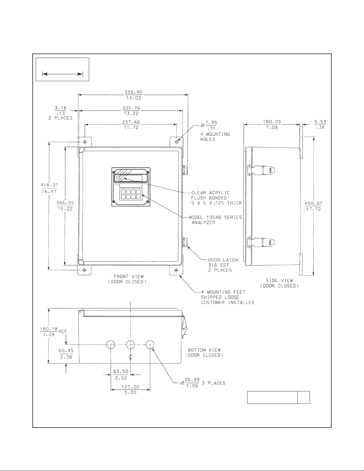
Wall Mount Enclosure: NEMA 4X, Heavy duty fiberglass,
reinforced thermoplastic.
356 X 450 X 180 mm (14 X 17.7 X 7.1 in.)
Dimensions include latches and mounting feet
Front Panel: Membrane keypad with tactile feedback and user
selectable security.
Digital Display: LCD, black on grey, Optional red LED
Character Height: 18 mm (0.7 in.)
Electrical Classification:
FM Class I, Div. 2, Group A thru D
28 Vdc relays - 5.0 amps resistive only
150 mA - Groups A & B; 400 mA - Group C ;
540 mA - Group D; Ci = 0; Li = 0
CSA Class I, Div. 2, Group A thru D.
28 Vdc, 110 Vac & 230 Vac relays
5.0 Amps resistive only
Wall Mount Enclosure: General Purpose
Power: 100 - 127 VAC, 50/60 Hz ± 6%, 4.0 W
200 - 253 VAC, 50/60 Hz ± 6%, 4.0 W
EMI/RFI: EN61326
LVD: EN61010-1
Model option -20 (Wall Mount Enclosure) does not meet
CE requirements
Current Output: Isolated, 0-20 mA or 4-20 mA into
600 ohms maximum load at 115/230 Vac or
550 ohms maximum load at 100/200 Vac;
direct or reverse output; dampening: 0-255 sec
Ambient Temperature: -10 to 65°C (14 to 149°F);
-50 to 65°C (-58 to 149°F) with optional
heater in wall mount enclosure.
Ambient Humidity: LED: 0-95% RH
LCD: 0-85% RH @ 50°C
Alarms: Dual, field selectable High/Low, High/High, Low/Low
Alarm 2 configurable as a fault alarm
Time Delay 0 to 255 seconds
Dual Setpoints, continuously adjustable
Hysteresis adjustable up to 2.00 ppm
for low side/High Alarm and high side/Low Alarm
Interval Timer: Interval: 10 min. to 2999 days
On Counts: 1 to 60
On Duration: 0.1 to 299.9 seconds
Off Duration: 0.1 to 299.9 seconds
Wait Duration: 0.1 to 299.9 seconds
Controls dedicated relay
Relay Contacts: Epoxy Sealed Form A contacts, SPST,
Normally Open.
Resistive
Inductive
28 VDC 5.0 Amps 3.0 Amps
115 VAC 5.0 Amps 3.0 Amps
230 VAC 5.0 Amps 1.5 Amps
Weight/Shipping Weight: 1.1 kg/1.6 kg (2.5 lb/3.5 lb)
1.3 INSTRUMENT SPECIFICATIONS
Operating Ranges: 0-20 ppm (mg/l); 0-250% saturation; 0-50°C
Accuracy: ± 1% full scale
Repeatability: ± 0.1% of range
Stability: Zero Drift: ± 1% full scale/month
Span Drift: ± 1% full scale/month
Response Time: 0-95% full scale in less than 15 secs
Temperature Correction for Membrane Permeability:
Automatic between 0-50°C. Temperature compensation can
be disabled if desired.
Page 8

2
MODEL 1054B DO SECTION 1.0
DESCRIPTION AND SPECIFICATIONS
The Model 1054B Dissolved Oxygen Microprocessor Analyzer: Housed in a NEMA 4X corrosion resistant,
weatherproof housing suitable for panel, pipe, or wall mounting. Standard features include isolated digital display,
current outputs, dual programmable alarms and timer relay, default settings, and automatic or manual temperature compensation.
MODEL
1054BDO MICROPROCESSOR ANALYZER (3.5 lbs./1.5 kg)
CODE STANDARD ENCLOSURE OPTIONS
01 LCD Display
02 LED Display
CODE OPTIONS
20 Wall Mount Enclosure (wall mount enclosure does not meet CE requirements)
1054BDO 01 20 EXAMPLE
1.4 ORDERING INFORMATION
P/N DESCRIPTION
22966-00 PCB, LCD Digital Display
23025-01 Panel Mounting Kit
23245-01 PCB, LED Digital Display
32937-00 Gasket, Rear Cover
32938-00 Gasket, Front Cover
9100157 Fuse, .10A, 250V, 3AB,
Slo Blo
23739-00 PCB, Power Supply
23740-00 PCB, Motherboard
23695-12 Keyboard Overlay,
LCD Version
23695-13 Keyboard Overlay,
LED Version
33469-00 Enclosure Body
33470-00 Enclosure, Rear Cover
9100160 Fuse, .250A, 125V,
Axial lead PICO II
9100189 Fuse, .750A, 125V,
Axial lead PICO II
23666-00 PCB, CPU, Dissolved
Oxygen
TABLE 1-1. Replacement Parts TABLE 1-2. Accessories
P/N DESCRIPTION
2001492 Tag, Stainless Steel, Specify
Marking
23053-00 Mounting Bracket, 2-inch Pipe
23054-01 Mounting Bracket, Wall, with
Junction Box
23268-01 Heater, 115 VAC, 50/60 Hz,
1054B (Code 20 Only)
23268-02 Heater, 230 VAC, 50/60 Hz,
1054B (Code 20 Only)
Page 9

3
MODEL 1054B DO SECTION 2.0
INSTALLATION
SECTION 2.0
INSTALLATION
2.1 GENERAL. The analyzer is suitable for outdoor
use. However, it should be located in an area where
temperature extremes and vibrations are minimized or
absent. Installation must be performed by a trained
technician.
2.2 UNPACKING AND INSPECTION. Inspect the
analyzer for shipping damage. If damaged, notify the
carrier immediately. Confirm that all items shown on
the packing list are present. Notify Rosemount
Analytical if items are missing.
2.3 MECHANICAL INSTALLATION. Select an installation site that is at least one foot from any high voltage conduit, has easy access for operating personnel,
and is not in direct sunlight. Mount the analyzer as follows:
1. Remove the four screws that secure the rear
cover of the enclosure.
2. Remove the four screws holding the front panel
assembly of the enclosure and carefully pull the
front panel and connected printed circuit boards
straight out.
3. Follow the procedure for the appropriate mounting
configuration: Section 2.3.1 for panel mounting,
Section 2.3.2 for wall mounting, Section 2.3.3 for
pipe mounting.
2.3.1 Panel Mounting (Standard). The Model 1054B
is designed to fit into a DIN standard 137.9 mm X
137.9 mm (5.43 in. X 5.43 in.) panel cutout (Refer to
Figures 2-1 and 2-2).
1. Prepare the analyzer as described in Section 2.3.
2. Install the mounting latches as described in Figure
2-2 (latches are shown oversize for clarity). If the
latches are not installed exactly as shown, they
will not work correctly. The screws provided are
self-tapping. Tap the screw the full depth of the
mounting latch (refer to side view) leaving a gap
greater than the thickness of the cutout panel.
3. Align the latches as shown and insert the analyzer enclosure through the front of the panel cutout.
Tighten the screws for a firm fit. To avoid damaging the mounting latches, do not use excessive
force.
4. Replace the front panel assembly. Circuit boards
must align with the slots on the inside of the enclosure. Assure that the continuity wire is connected
to the rear cover and the interface board’s closest
mounting screws. Replace the door and four front
panel screws.
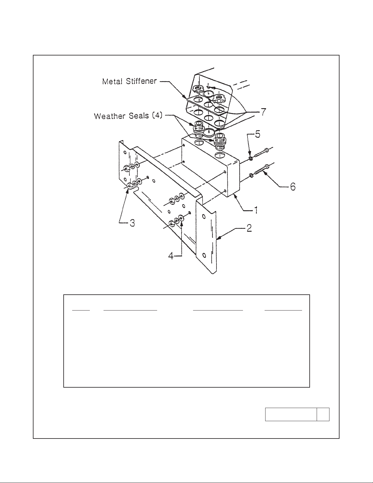
2.3.2 Wall Mounting Plate with Junction Box
(P/N 23054-01). Refer to Figures 2-3 and 2-4.
1. Prepare the analyzer as described in Section 2.3.
2. Mount the junction box and bracket to the analyzer with the hardware provided. All wiring can be
brought to the terminal strip prior to mounting the
analyzer.
3. Place the metal stiffener on the inside of the analyzer and mount the two 1/2-inch conduit fittings
using two each weather seals as shown. Mount
NEMA 4X conduit plug (included) into center conduit hole.
4. Mount the analyzer to the junction box using the
1/2-inch conduit fittings.
5. Complete wiring from the analyzer to the junction
box (Refer to Figure 2-4).
NOTE
Run sensor wiring out of the left opening
(From front view) to J-Box. All others out
right opening to J-Box.
2.3.3 Pipe Mounting (P/N 23053-00). The 2-inch pipe
mounting bracket includes a metal plate with a cutout
for the analyzer (Refer to Section 2.3 for mounting the
analyzer into the plate). Mounting details are shown in
Figure 2-5.
2.3.4 Wall Mount Enclosure (option -20). See
Figure 2-7 for installation details.
Page 10

2.4 ELECTRICAL WIRING.
All electrical connections are made to terminal strips
on the rear panel (interface board) of the instrument.
To access the interface board, remove the four (4)
screws securing the rear cover of the enclosure.
Gently pull away the rear cover, which is connected to
the back panel by a continuity wire. If the continuity
wire is disconnected for any reason, it must be reconnected to the nearest interface board mounting screw
before the rear enclosure cover is replaced.
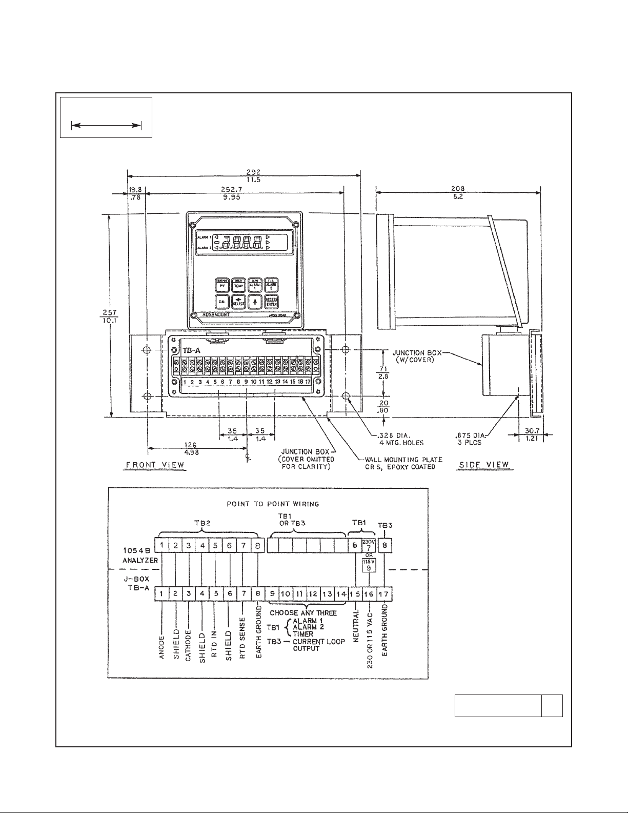
The three openings in the bottom rear of the Model
1054B analyzer housing accommodate 1/2-inch conduit fittings. Looking at the analyzer from the front, the
conduit opening on the left is for sensor wiring, the
center opening is for signal output, and the opening
on the right is for timer, alarm, and AC connections.
Always run sensor wiring in a separate conduit from
power wiring.
NOTE
For best EMI/RFI protection, shield the
output cable and enclose it in an earthgrounded, rigid metal conduit. Connect
the outer cable shield to the earth
ground terminal on TB-A when using the
wall mounting junction box (Fig. 2-4) or
to terminal 8 on TB3 when wiring directly to the instrument (Fig. 2-6).
The sensor cable should also be shielded. When wiring directly to the instrument, connect the outer shield of the
sensor cable to the earth ground of the
instrument on terminal 8 of TB2. If the
outer shield of the sensor cable is braid,
an appropriate metal cable gland fitting
may be used to connect the braid to
earth ground by way of the instrument
case. When wiring to the wall mounting
junction box, connect the outer shield of
the sensor cable to the earth ground terminal on TB-A.
2.4.1 Power Input Wiring. The Model 1054B can be
configured for either 115 VAC or 230 VAC power.
Connect AC power to TB1-8 and -9 (115 VAC) or TB17 and -8 (230 VAC) ground to the ground terminal at
TB3-8 (refer to Figure 2-6).
4
MODEL 1054B DO SECTION 2.0
INSTALLATION
CAUTION
The sensitivity and stability of the analyzer
will be impaired if the input wiring is not
grounded. DO NOT apply power to the
analyzer until all electrical connections are
verified and secure. The following precautions are a guide using UL 508 as a safeguard for personnel and property.
1. AC connections and grounding must be in compliance with UL 508 and/or local electrical codes.
2. The metal stiffener is required to provide support
and proper electrical continuity between conduit
fittings.
3. This type 4/4X enclosure requires a conduit hub
or equivalent that provides watertight connect,
REF UL 508-26.10.
4. Watertight fittings/hubs that comply with the
requirements of UL 514B are to be used.
5. Conduit hubs are to be connected to the conduit
before the hub is connected to the enclosure,
REF UL 508-26.10.
6. If the metal support plate is not used, plastic fittings must be used to prevent structural damage
to the enclosure. Also, appropriate grounding lug
and awg conductor must be used with the plastic
fittings.
2.4.2 Output Wiring. The signal output and alarm
connections are made to terminals 1 through 6 of TB1
and TB3-1 and 2. (Refer to Figure 2-6).
Page 11

5
FIGURE 2-1. Panel Mounting Cutout
WHEN INCH AND METRIC DIMS
ARE GIVEN
MILLIMETER
INCH
DWG. NO. REV.
41054B01 B
MODEL 1054B DO SECTION 2.0
INSTALLATION
Page 12

6
MODEL 1054B DO SECTION 2.0
INSTALLATION
FIGURE 2-2. Panel Mounting Tab Installation
DWG. NO. REV.
41054A26 A
SIDE VIEW
Page 13
7
MODEL 1054B DO SECTION 2.0
INSTALLATION
FIGURE 2-3. Wall Mounting J-Box Installation
DWG. NO. REV.
41054A27 A
ITEM PART NUMBER DESCRIPTION QUANTITY
1 23058-01 S Assy, J-Box 1
2 33030-00 Bracket, wall mtg 1
3 9900600 Nut, 6-32 Hex 4
4 9910600 Washer, Flat #6 4
5 9910610 Washer, Lock Int. #6 8
6 9600612 Screw, 6-32 X .75 4
7 9510048 Seal, Weathertight 1
Page 14
8
MODEL 1054B DO SECTION 2.0
INSTALLATION
FIGURE 2-4. Wall Mounting J-Box Wiring
WHEN INCH AND METRIC DIMS
ARE GIVEN
MILLIMETER
INCH
DWG. NO. REV.
41054B17 E
Page 15

9
MODEL 1054B DO SECTION 2.0
INSTALLATION
FIGURE 2-5. Pipe Mounting Installation
WHEN INCH AND METRIC DIMS
ARE GIVEN
MILLIMETER
INCH
DWG. NO. REV.
41054B02 C
Page 16

10
MODEL 1054B DO SECTION 2.0
INSTALLATION
WHEN INCH AND METRIC DIMS
ARE GIVEN
MILLIMETER
INCH
DWG. NO. REV.
41054B07 B
FIGURE 2-6. Electrical Wiring
Page 17
MODEL 1054B DO SECTION 2.0
INSTALLATION
FIGURE 2-7. Wall Mount Enclosure (Option -20)
DWG. NO. REV.
41054B43 A
WHEN INCH AND METRIC DIMS
ARE GIVEN
MILLIMETER
INCH
11
Page 18

Configuration is all accomplished through a series of
menus located within the set mode menu. To access
these set mode menus the ACCESS keypad is
pressed TWICE in RAPID succession.
Once inside the Set mode menu, use the scroll keypad to scroll through the menu list. When the menu
desired is displayed, release the scroll keypad.
To enter the submenus press the SELECT keypad. If
the submenu allows editing, the item will flash that can
be edited. If not, use the scroll keypad to scroll through
the next list of submenus . SELECT will enter this submenu and if it is editable, the field will flash.
To exit the menu and SAVE the new value, press the
ENTER keypad.
To exit the menu without saving the edited value, press
the PV keypad to jump out of the set menu program with
out saving value. To change other parameters will
require re-entering the set menu program.
Figure 3-4 explains the various fields surrounding the
Primary process on the LC display.
Table 3-1 describes the functions accessible with the
8 keypads, the number of times to press the keypad to
access, and its’ function when used with the select
keypad and set menu.
Tables 3-2 and 3-3 describe the meaning of the various
mnemonics used on the display. They are categorized
by their use in either menus, or as process information.
MODEL 1054B DO SECTION 3.0
DESCRIPTION OF CONTROLS
SECTION 3.0
DESCRIPTION OF CONTROLS
3.1 KEYBOARD FUNCTIONS. All operations of the
Model 1054B Microprocessor Analyzer are controlled
by the eight (8) keypads on the front of the instrument.
These keypads are used to :
1. Display parameters other than the primary parameter.
2. Edit setpoints for alarms, set up specific output
current value for simulation, calibrate temperature,
conductivity, etc.
3. Configure display for temperature units, for automatic temperature compensation, alarm usage,
setting timer functions, security, and output range.
To view, and not change parameters, other than the
primary parameter requires only a simple keystroke
routine. As shown in Figure 3-1, a single keypress
accesses the lower function printed on the keypad.
Quick, double keypresses access the top function
printed on the keypad.
To edit any of these parameters, requires one more
operation. After displaying the value associated with
the parameter selected, press the SELECT keypad.
As seen in Figure 3-2, this will display the numerical
value, and the first digit will be flashing to indicate this
value may be edited.
All changes to the operating program that set-up the
instrument display are made through the set menu program. See Figure 4.1.
FIGURE 3-1. Function Select on Keypad.
Single press of the keypad will access the
present Dissolved Oxygen reading. Read only.
1. Press Key.
2. AdJ shows briefly.
3. Numbers show with digit flashing.
1 .Press Key twice.
2. Lo shows briefly.
3. Zero point is displayed.
SELECT
ZERO
ALARM
1
OUTPUT
PV
FIGURE 3-2. Accessing Editing Function.
1. Press twice in rapid succession.
2. See SEt on display. Confirms entry
into set mode menu.
3. First menu item is displayed.
Analyzer now ready to configure.
4. Use the SCROLL keypad to rotate
through the available menus.
ACCESS
ENTER
SEt
Cin
é
FIGURE 3-3. Accessing Configuration Menus
Quick double press will access the current
output current value in mA or %. Read only.
ç
12
Page 19
13
MODEL 1054B DO SECTION 3.0
DESCRIPTION OF CONTROLS
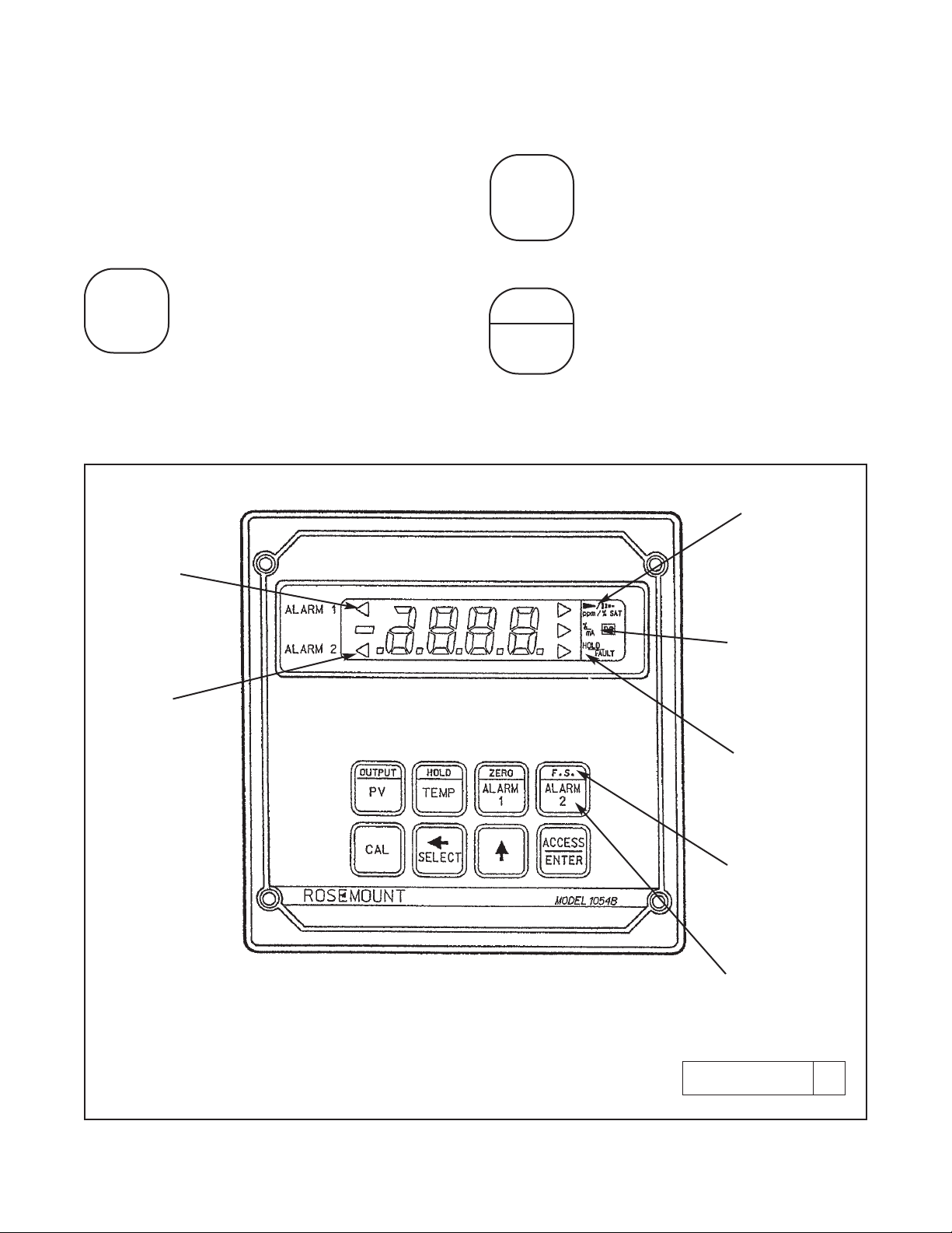
FIGURE 3-4. LCD Display
RELAY 1
ACTIVATED
RELAY 2
ACTIVATED
DISSOLVED
OXYGEN :
PPMFLAG ON;
% SATURATION
FLAG BLINKING
% VALUE FLAG ON;
mA FLAG BLINKING
HOLD STATUS
FLAG ON;
FAULT FLAG BLINKING
UPPER FUNCTION PRESS
TWICE
QUICKLY
LOWER FUNCTION PRESS
ONCE
3.1.1 Item Selection and Value Adjustment Keys.
The three keys located on the lower right side of the
keypad are used for menu navigation, value adjustment and entry, and item selection. These keys perform the following functions:
A. SELECT/Shift (
çç
) Key. This key is
used to select the displayed menu, or for
shifting to the next digit in the Numeric
Display.
B. SCROLL Key (é). This key is used to
scroll through menu when selected, or
scroll through digits on the active (flashing) Numeric Display, or move the decimal point and ppm/% SAT display.
Holding key down auto scrolls display.
C. ACCESS/ENTER Key. This key is
used to ACCESS the Set Mode (Section
4.1.2) and to ENTER the displayed value
into memory (from Numeric Display).
ç
SELECT
é
ACCESS
ENTER
DWG. NO. REV.
41054B27 A
Page 20

14
MODEL 1054B DO SECTION 3.0
DESCRIPTION OF CONTROLS
TABLE 3-1. Key Description
Displays - current output (mA or % full scale).
Set Function (w/SELECT) - Simulates current
output.
Displays – low Lo setpoint; the low end of the dissolved oxygen range that corresponds to 0 or 4
mA DC output.
Displays – high HI setpoint; the high end of the
dissolved oxygen range that corresponds to 20
mA DC output.
Select sub menu (mnemonic display).
Shift to next digit (numeric display).
Activate decimal point adjustment.
Scroll through menu (mnemonic display).
Scroll digits (numeric display).
Holding key down autoscrolls digits
or set menu items.
Press twice quickly to access set-up
menu.
Enter displayed value into memory.
Enter displayed menu item (flashing) into
memory.
Displays - Barometric pressure setting.
Used to calibrate the analyzer and the
dissolved oxygen sensor loop in air.
Set Function (w/select)-One point standardization of % saturation.
Displays - Alarm 1 setpoint.
Set Function (w/SELECT) - Sets Alarm 1
Setpoint.
Displays - DO in ppm or % saturation.
Set Function (w/SELECT) - One point
standardization of DO.
(PV = Process Variable)
Initiates or removes analyzer from hold condition.
Displays - process temperature (°C or
°F).
Set Function (w/SELECT) - One point
standardization of temperature.
Displays - Alarm 2 setpoint.
Set Function (w/SELECT) - Sets Alarm 2
Setpoint.
HOLD
TEMP
OUTPUT
PV
ZERO
ALARM 1
F.S.
ALARM 2
CAL
ç
SELECT
é
ACCESS
ENTER
CAUTION
Air calibrate only when the sensor is fully polarized
and stabilized in ambient air.
SECOND FUNCTION (PRESS TWICE QUICKLY)MAIN FUNCTION (PRESS ONCE)
NOTE
When no key is pressed for a period
of 60 seconds the analyzer will default
to reading DO.
CAUTION
The HOLD function and the CAL
function are not read functions. Refer
to Sections 4.16 and 5.0 respectively.
Page 21

15
MODEL 1054B DO SECTION 3.0
DESCRIPTION OF CONTROLS
TABLE 3-2. Information Mnemonics
MNEMONIC DESCRIPTION
AdJ Adjustment to value reading
bAd Incorrect entry
HI Displays high range value for current output
itr Interval timer activated
Lo Displays low range value for current output
LOC Access locked - enter security code
SEt Set mode
SiC Simulates current output (mA)
SiP Simulates current output (percent)
SP1 Displays Alarm 1 setpoint
SP2 Displays Alarm 2 setpoint
Std Standardize DO
AL1 Alarm 1 setup
AL2 Alarm 2 setup
Atc Automatic temp. comp.
bAr Bars
br Barometric reset
bP Barometric pressure
o
C Temperature °C
COd Security Code
cnt Count on times
CUr Config. mA output display
Cur Config. fault output
cur Default current setpoint
dAY Days
dFt Fault Configuration
do Dissolved oxygen
d-O Display output
d-t Display temperature
doc Display output in mA
doF Delay off time
don Delay on time
dPn Dampen output
dtS Display test
dur Waiting period duration
o
F Temperature °F
Fct Solubility factor
FLt Fault alarm set
Hi Relay action - high
H-L Alarm logic
hr Hours
HYS Hysteresis
iHg Inches mercury
in Display sensor input
int Interval period
Int Timer setup
Lo Relay action - low
non No action on fault
OFF Alarm off
oFF Function off
ont On time duration
On Alarm on
on Function on
OFt Off time duration
OUt Current output
Pct Display output in percent
PPu Parts per million
rng Range units
rL1 Relay 1 fault setup
rL2 Relay 2 fault setup
SAt % saturation
SEC Seconds
SHO Show fault history
SIt Saline solution factor
Snr Sensor type
SoL Solubility Correction
t-C Temperature config.
tiL Display time remaining
tOn Timer status
UEr Display version number
uHg Millimeters mercury
uin Minutes
420 4mA to 20mA output
020 0mA to 20mA output
-0- Analyzer zero
1 499 or 491 Sensor
Compatible
2 492 or 493 Sensor
Compatible
TABLE 3-3. Set Function Mnemonics
NOTE: See Table 8-1 for Fault Mnemonics.
Page 22

16
MODEL 1054B DO SECTION 4.0
CONFIGURATION
SECTION 4.0
CONFIGURATION
4.1 GENERAL. This section details all of the items
available in the Set Mode and the setpoint adjustment
procedures to configure the Model 1054B Dissolved
Oxygen Analyzer. Refer to Table 3-3 and Figure 4-1.
4.1.1 Set Mode (SEt). Most of the analyzer’s configu-
ration is done while in the Set Mode. Please refer to
Figure 4-1 for the layout of all menu items. All menu
variables are written to the analyzer’s EEPROM
(memory) when selected and remain there until
changed. As these variables remain in memory even
after the analyzer’s power is removed, the analyzer
configuration may be performed prior to installing it.
1. Make sure the analyzer loop is properly wired.
Power up the analyzer. Only power input wiring is
required for analyzer configuration. (Refer to
Section 5.2 regarding polarization voltage.) The
analyzer’s display will begin showing values
and/or fault mnemonics. All fault mnemonics will
be suppressed while the analyzer is in Set Mode
(the fault flag will continue to blink).
2. Enter Set Mode. Pressing the ACCESS key twice
will place the analyzer in Set Mode. The display
will show SEt to confirm that it is in Set Mode. It
will then display the first item in the set menu br.
The analyzer is now ready for user configuration.
NOTE:
If LOC displays, the Keyboard Security
Code must be entered to access the Set
Mode. (Refer to Section 6.0.) To get out of
the Set Mode, press the PV key. Refer to
the Configuration Worksheet on page 18
for the analyzer ranges and factory settings.
4.1.2 Configuration Work Sheet. The Configuration
Worksheet provides the range of the various functions, the factory settings, and a column for user’s settings. As you proceed through the configuration
procedures for each function of the analyzer, fill in the
appropriate information in the USER column. The configuration may be done in any order. However, it is
recommended that it be done in the order as shown in
the worksheet.
4.1.3 Barometric Pressure. Display Mnemonic br.
This function is used to update the barometric pressure setting after the analyzer/sensor loop has been
air calibrated and the sensor installed in the process.
Refer to Section 5.0, Start-up Calibration. It is only
used for the % SAT mode.
4.1.4 Analyzer Zero. Display Mnemonic -O-. This
function is used to zero the analyzer/sensor loop.
Refer to Section 5.3.2, Analyzer Zero.
4.1.5 Sensor Input. Display Mnemonic in. This func-
tion is used to display current input from the sensor.
Refer to Section 8.2.4, Sensor Troubleshooting, for
more information.
Page 23

17
MODEL 1054B DO SECTION 4.0
CONFIGURATION
H-L
HYS
don
doF
On
OFF
br
-0in
AL1
AL2
Int
t-C
Out
rng
bP
SoL
Snr
dFt
UEr
dtS
COd
Hi
Lo
tOn
int
cnt
ont
OFt
dur
tiL
OFF
on
SEC
uin
hr
dAY
o
F
o
C
doc
Pct
PPu
SAt
Fct
SIt
1
2
on
oFF
non
uHg
iHg
bAr
non
cur
rL1
rL2
Cur
SHO
on
oFF
On
FLt
OFF
420
020
d-t
Atc
dPn
CUr
d-O
FIGURE 4-1. Set Function Menu
SEt
Page 24

18
RANGE FACTORY SET USER SET
A. Alarm 1 Setup (AL1)
1. Alarm Status (On/OFF) On _________
2. High or Low (H-L) (Hi/Lo) Lo _________
3. Hysteresis (HYS) 0-2.00 0.00 _________
4. Delay Time On (don) 0-255 sec. 000 Seconds _________
5. Delay Time Off (doF) 0-255 sec. 000 Seconds _________
B. Alarm 2 Setup (AL2)
1. Alarm Status (On/FLt/OFF) On _________
2. High or Low (H-L) (Hi/Lo) Hi _________
3. Hysteresis (HYS) 0-2.00 0.00 _________
4. Delay Time On (don) 0-255 sec 000 Seconds _________
5. Delay Time Off (doF) 0-255 sec 000 Seconds _________
C. Interval Timer (int)
1. Active Status (tOn) (OFF/on) OFF _________
2. Interval Time (int) 10 min to 2,999 days 1 Day _________
3. Count (cnt) 1 to 60 5 _________
4. On Time (ont) 0.1 to 299.9 sec 1 Second _________
5. Off Time (OFt) 0.1 to 299.9 sec 1 Second _________
6. Duration (dur) 0.1 to 299.9 sec 2 Seconds _________
D. Temperature Setup (t-C)
1. Display Temperature (d-t) (oC/oF)
o
C _________
2. Automatic TC (Atc) (on/oFF) on _________
a. Manual Temp. Value 0°C to 80°C _________
E. Current Output Setup (OUt)
1. mA Output (CUr) (020/420) 420 _________
2. Display Current Output (d-O) (Pct/doc) doc _________
3. Dampen Current Output (dPn) 0-255 sec. 0.0 Seconds _________
F. Output Range Setup (rng)
1. Parts Per Million (PPu) 0-20 PPu _________
2. Percent Saturation (SAt) 0-250% _________
G. Barometric Pressure Setup (bP)
1. Millimeters Mercury (uHg) 500-1000 uHg _________
2. Inches Mercury (iHg) 19.67-39.37 _________
3. Bars (bAr) 0.666-1.333 _________
H. Solubility Correction Factor Setup (SoL)
1. Solubility Constant (Fct) 0.09 - 9.00 1.00 _________
2. Solubility Factor For Saline Solutions (S1t) 0.00 - 2.00 0.00 _________
I. Sensor compatibility (Snr)
1. Model 499 or 491(1) / Model 492 or 493 (2) 1 _________
J. Default Setup (dFt)
1. Relay 1 Default (rL1) (non/oFF/on) non _________
2. Relay 2 Default (rL2) (non/oFF/on) non _________
3. Current Output Default (Cur) (non/cur) non _________
4. Current Output Held non _________
K. Keyboard Security Setup (COd)
1. Keyboard Security Required 001-999 _ _________
2. Keyboard Security Not Required 000 000 _________
Alarm Setpoints Setup
1. Alarm 1 (SP1) 0-20 ppm 0 ppm _________
2. Alarm 2 (SP2) 0-20 ppm 20 ppm _________
Current Output Setup
1. Zero (0 or 4 mA) 0-20 ppm 0 ppm _________
2. F.S. (20 mA) 0-20 ppm 20 ppm _________
TABLE 4-1. Configuration Worksheet
Use this worksheet to assist in the configuration of the analyzer.
MODEL 1054B DO SECTION 4.0
CONFIGURATION
Page 25

19
MODEL 1054B DO SECTION 4.0
CONFIGURATION
4.2 ALARM 1 AND 2. Display Mnemonic AL1 or AL2.
Used to set alarm relay logic (See note below). Each
alarm is configured separately. Choices are (see note
below):
A. On. Display Mnemonic On. Select this item if Alarm 1
or 2 is to be used. If On is selected, AL1 or AL2 may be
configured for either high (Hi) or low (Lo) alarm.
B. Off. Display Mnemonic 0FF. Select this item if Alarm 1
or 2 will not be used or to temporarily disable the alarm.
Alarm 1 or 2 setpoint will display oFF if this item is selected. All other Alarm 1 or 2 settings are ignored.
C. Fault. (In addition to On and 0FF, Alarm 2 may be con-
figured to a fault alarm). Display Mnemonic FLt. Select
this item to make Alarm 2 a fault alarm. Relay 2 will
energize when the analyzer experiences a fault condition. Alarm 2 setpoint will display FLt if this item is selected. All other Alarm 2 settings are ignored.
D. Alarm Logic. Display Mnemonic H-L. Select this
item for high or low alarm logic. High alarm logic activates the alarm when the reading is greater than the
setpoint value. Low alarm logic activates the alarm
when the reading is less than the setpoint value.
E. Relay Hysteresis. Display Mnemonic HYS. Sets the
relay hysteresis (dead band) for deactivation after reading
has passed the alarm setpoint. May be set from 0 to 2.00.
Hysteresis is used to delay the alarm relay deactivation
on the low side of the high alarm setpoint, or on the high
side of the low alarm setpoint. This feature is used to prevent or minimize alarm chattering.
Example:
High alarm setpoint is 6.00 ppm, and hysteresis is
1.00 ppm. The alarm will activate when the DO
reading exceeds 6.00 ppm and will remain activated until the reading drops to below 5.00 ppm.
F. Delay Time On. Display Mnemonic don. Sets time
delay for relay activation after alarm setpoint is
reached. May be set from 0 to 255 seconds. Normal (no
alarm) state restarts time from zero. Use when a fixed
time should pass before relay activation occurs.
G. Delay Time Off. Display Mnemonic doF. Sets time
delay for relay deactivation after alarm setpoint is
reached. May be set from 0 to 255 seconds. Alarm state
restarts time from zero. Use when a fixed time should
pass before relay deactivation occurs.
4.2.1 Alarm Setup (AL1/AL2). Refer to Figure 4-1 and
Table 4-1.
1. Enter Set Mode by pressing the ACCESS key twice.
2.
SCROLL (é) until AL1 or AL2 appears on the display.
3. SELECT to move to the next menu level. On,
OFF or FLt (AL2 only) will display.
4. SCROLL (é ) to display desired item then
SELECT.
5. If OFF is selected, display will show oFF to
acknowledge. Press the ENTER key to return to
AL1 or AL2, concluding routine.
If On is selected, display will show on to acknowledge, then display H-L. Proceed to Step 6.
If FLt is selected (AL2 only), display will show
FLt to acknowledge. Press the ENTER key to
return to AL2.
6. SELECT On. Hi or Lo will display (flashing).
7. SCROLL (é) to the desired item and ENTER it
into memory. Display will return to H-L. If
changes to relay activation logic are desired,
proceed to Step 8, otherwise Step 12.
8. SCROLL (é) to display HYS, don or doF then
SELECT. Numerical display will flash to indicate
that a value is required.
9. Use the SCROLL (é) and SELECT keys to display the desired value.
10. ENTER the value into memory. Analyzer will
acknowledge and return to display of last item
selected. Repeat Step 8 if further changes are
desired, otherwise Step 12.
11. Repeat Step 3 for the other Alarm’s settings as
required.
12. Press the ENTER key to return to the first level
of the Set Menu, or press the PV key to get out
of the Set Mode.
Page 26

20
MODEL 1054B DO SECTION 4.0
CONFIGURATION
4.3 INTERVAL TIMER. Display Mnemonic Int. This
item is used to set the interval timer’s relay logic. The
timer can be used as a sensor maintenance reminder.
Choices are:
A. Interval Timer Enable/Disable. Display Mnemonic
tOn. Select this item to begin interval cycle on or disable interval cycle OFF.
B. Interval Period. Display Mnemonic int. Select this
item to set the time period between end of wait duration and beginning of new on-off cycle. SEC for seconds, uin for minutes, hr for hours, and dAY for days.
May be set from 1 second to 2999 days. Time of less
than 10 minutes is not recommended.
C. On Periods Per Cycle. Display Mnemonic cnt.
Select this item to enter the number of on periods per
cycle. May be set from 1 to 60 on periods.
D. Duration of On Periods. Display Mnemonic ont.
Select this item to enter the relay activation time for
each on period. May be set from 0.1 to 299.9 seconds.
E. Duration of Off Periods. Display Mnemonic OFt.
Select this item to enter the relay
deactivation time
between each on period during the control cycle. Valid
when cnt is 2 or greater. May be set from 0.1 second
to 299.9 seconds.
F. Wait Duration. Display Mnemonic dur. Select this
option to enter the wait duration after the last on period in a cycle. May be set from 0.1 to 299.0 seconds.
The wait duration can be used for sensor recovery
after a cycle to allow the process to stabilize before
the next interval time starts again.
NOTE:
The Model 1054B DO is placed on hold
during the control cycle (from first on period through the wait duration). The analyzer will simulate a fault condition and briefly
show itr every eight seconds. The display will continue to show the measured
value.
G. Interval Time Remaining. Display Mnemonic tiL.
Select this item to display the time remaining to the
next control cycle. If selected during the control cycle,
display will show ---.
4.3.1 Interval Timer Set Up (Int). Refer to Figure 4-1
1. Enter Set Mode by pressing the ACCESS key
twice.
2. Press the SCROLL (é) key until Int appears on
the display.
3. Press the SELECT key to move to the next menu
level. tOn will display. Press the SELECT key
again.
4. Press the SCROLL (é) key to display on (if the
interval timer is to be used) or OFF (if the interval
timer is not to be used) and press the ENTER
key. If interval timer configuration is required, proceed to Step 5, otherwise Step 15.
5. Press the SCROLL (é) key to display the next
menu item, int. Press the SELECT key.
6. Press the SCROLL (é ) key to display desired
duration and SELECT it.
7. Press the SCROLL (é) key and SELECT key to
display the desired value and press the ENTER
key.
8. Repeat Steps 6 and 7 as needed.
9. Press the ENTER key to return to the interval
period int menu.
10. SCROLL (é) down to cnt (on periods per cycle)
Press the SELECT key and the current setting
will flash. Repeat Step 7.
11. SCROLL (é) down to ont (duration of on times).
Press the SELECT key and the current setting
will flash. Repeat Step 7.
12. SCROLL (é) down to OFt (duration of off times).
Press the SELECT key and the current setting
will flash. Repeat Step 7.
13. SCROLL (é) down to dur (waiting time after the
last on cycle). Press the SELECT key and the
current setting will flash. Repeat Step 7.
14. SCROLL (é) down to tiL (time interval lapse).
Press the SELECT key to display the time
remaining. Press the ENTER key to return to tiL.
15. Press the ENTER key to return to the first level of
the Set Menu, or press the PV key to get out of
the Set Mode.
Page 27

21
MODEL 1054B DO SECTION 4.0
CONFIGURATION
4.4 TEMPERATURE CONFIGURATION. Display
Mnemonic t-C. Select this item for temperature reading and compensation choices.
A. Temperature Display. Display Mnemonic d-t.
Select this item to toggle between °F and °C temperature display. The analyzer will show all temperatures
in the units selected.
B. Automatic Temperature Compensation. Display
Mnemonic Atc. The analyzer will use the temperature
input from the sensor for temperature compensation
when on is selected. When oFF is selected, the analyzer will use the value entered by the user for manual
temperature compensation. This manual temperature
option is useful if the temperature sensor is faulty or
not on line. Temperature specific faults will be disabled
(Refer to Table 8-1).
4.4.1 Temperature Setup (t-C). Refer to Figure 4-1.
1. Enter Set Mode by pressing the ACCESS key
twice.
2. Press the SCROLL (é) key until t-C appears on
the display.
3. Press the SELECT key to move to the next menu
level. d-t will display.
4. Press the SELECT key. oC or oF will be displayed
flashing. SCROLL (é) to desired unit.
5. Press the ENTER key when the desired temperature unit is displayed. The analyzer will now display temperature readings in this unit until
changed.
6. SCROLL (é) to Atc then press the SELECT key.
on or oFF will be displayed flashing. SCROLL (é)
to desired condition.
7. Press the ENTER key when the desired condition
is displayed.
8. If on was entered, proceed to Step 10. If oFF was
entered, the last temperature used for manual
compensation will be displayed with the right digit
flashing.
9. Use SCROLL (é) and SHIFT (ç) to display the
desired value. ENTER value into memory.
10. Press the ENTER key to return to the first level of
the Set Menu, or press the PV key to get out of
the Set Mode.
4.5 CURRENT OUTPUT. Display Mnemonic is OUt.
This item is used to select signal output configuration.
A. Output Dampening. Display Mnemonic dPn. This
function is used to filter out and spread out any
change in signal output. The number entered is the
sampling time (in seconds). Zero to 255 seconds may
be entered. If less than 1 second is entered, the signal
output change takes place immediately. If 1 to 255
seconds is entered, 63% of the signal output change
takes place in the first sampling time, then 63% of the
balance of the signal output change takes place in the
next sampling time, etc.
B. mA Output Range. Display Mnemonic CUr.
Selection of this item will allow choice of either 0 to 20
mA or 4 to 20 mA output range.
C. Display Output. Display Mnemonic d-O. This item
is used to select output display logic. Selecting this
item will allow the analyzer to display current output in
mA (when doc is entered) or in percent of full scale
output range (when Pct is entered). When the OUT-
PUT key is pressed, a steady flag indicates that the
value displayed is percent output. A flashing flag indicates mA output.
4.5.1 Output Setup (OUt). Refer to Figure 4-1.
1. Enter Set Mode by pressing the ACCESS key
twice.
2. Press the SCROLL (é) key until OUt appears on
the display.
3. Press the SELECT key to move to the next menu
level. dPn will display.
4. Press the SCROLL ( é ) key then SELECT
desired item.
5. If dPn is selected, numerical display will flash indicating that a value is required. Proceed to Step 6.
If CUr or d-O is selected, proceed to Step 7.
6. Use SCROLL (é) and SELECT keys to display
the desired value. ENTER into memory. Proceed
to Step 11.
7. If CUr is selected, 420 or 020 is displayed flashing.
Page 28

22
MODEL 1054B DO SECTION 4.0
CONFIGURATION
8. SCROLL (é) to the desired mA choice and press
ENTER. Proceed to Step 11.
9. If d-O is selected, Pct or doc is displayed flashing.
10. SCROLL (é) to the desired output unit and press
ENTER.
11. Press the ENTER key to return to the first level of
the Set Menu, or press the PV key to get out of
the Set Mode.
4.6 DISSOLVED OXYGEN RANGE UNITS. Display
Mnemonic rng. This function is used to select the
desired dissolved oxygen range units. One of the following two range units may be chosen:
A. (ppm) Display Mnemonic (PPu). Selecting this
item is for parts per million by weight of dissolved oxygen concentration.
B. Percent (%) Saturation Display Mnemonic (SAt).
Percent (%) saturation is the percent of dissolved oxygen in solution compared to the maximum amount of
dissolved oxygen the solution can hold at a given temperature and partial pressure of oxygen.
NOTE
Dissolved oxygen values will be displayed
in the unit selected until changed.
4.6.1 Dissolved Oxygen Analyzer Set Up (rng).
Refer to Figure 4-1.
1. Enter Set Mode by pressing the ACCESS key
twice.
2. Press the SCROLL (é) key until rng appears on
the display.
3. Press the SELECT key. PPu or SAt will be dis-
played.
4. Press the SCROLL (é ) key to display the
desired range unit.
5. Press the ENTER key to enter the desired unit
into memory.
6. Press the ENTER key to return to the first level of
the Set Menu, or press the PV key to get out of
the Set Mode.
4.7 BAROMETRIC PRESSURE UNITS. Display
Mnemonic bP. This function is used to select the barometric pressure units needed by the microprocessor
during the air calibration step. One of the following
three range units may be chosen:
A. bAr if the barometric pressure is given in bars.
B. iHg if the barometric pressure is given in inches of
mercury.
C. uHg if the barometric pressure is given in millimeters
of mercury.
4.7.1 Barometric Pressure Unit Set Up (bP). Refer to
Figure 4-1.
1. Enter Set Mode by pressing the ACCESS key
twice.
2. Press the SCROLL (é) key until bP appears on the
display.
3. Press the SELECT key. uHg, iHg, or bAr will be
displayed flashing.
4. Press the SCROLL (é) key to display the desired
barometric pressure unit.
5. Press the ENTER key to enter the desired unit into
memory.
6. Press the ENTER key to return to the first level of
the Set Menu, or press the PV key to get out of
the Set Mode.
Page 29

23
MODEL 1054B DO SECTION 4.0
CONFIGURATION
4.8 SOLUBILITY CORRECTION FACTOR. Display
Mnemonic SOL. This function is used to correct for the
solubility of oxygen in the process liquid which is other
than fresh water or is unique to the customer. One of
the following two factors may be chosen:
A. Fct – Solubility constant of the process liquid. For
fresh water, enter a value of 1.00. (The solubility
constant Fct range is 0.09 to 9.00.)
B. SIt – The salinity of the liquid measured in parts per
thousand by weight of salt. For fresh water, enter a
value of 0.00. (The typical parts per thousand salt by
weight range is 0.00 to 2.00.)
NOTE
10 ppt of salt is equivalent to 1.00 percent
salt.
4.8.1 Solubility Correction Factor Set Up (SoL).
Refer to Figure 4-1.
1. Enter Set Mode by pressing the ACCESS key
twice.
2. Press the SCROLL (é) key until SoL appears on
the display.
3. Press the SELECT key. Fct or S1t will be displayed. Press the SCROLL (é) key to display the
desired choice.
4. Press SELECT key. The last choice used will be
displayed flashing.
5. Use the SCROLL (é) and SELECT keys to dis-
play the desired value. Press the ENTER key to
enter the value into memory.
6. Press the ENTER key to return to the first level of
the Set Menu, or press the PV key to get out of
the Set Mode.
NOTE
Dissolved oxygen values will now be corrected according to the current factor value
entered until new values are entered.
4.9 SENSOR COMPATIBILITY. Display mnemonic
Snr. This item is used to select the proper sensor compatibility. There are to menu choices.
A. 1 - For use with the Model 499DO or Model 491.
B. 2 - For use with the Model 492 or Model 493.
The correct selection must be made to match the
Model 1054B DO to the output characteristics of the
sensor to be used.
4.9.1 Sensor Compatibility Set Up (Snr). Refer to
Figure 4-1.
1. Enter Set Mode by pressing the ACCESS key
twice.
2. Press the SCROLL (é) key until Snr appears on
the display.
3. Press the SELECT key. 1 or 2 will be displayed.
Press the SCROLL (é) key to display the appro-
priate choice.
4. Press the ENTER key to enter the value into memory.
5. Press the ENTER key to return to the first level of
the set menu, or press the PV key to return to normal operation.
4.10 DEFAULTS. Display Mnemonic dFt. This func-
tion is used to set the configuration of relay and output
conditions during a FAULT or HOLD status. A flashing
flag beside the HOLD/FAULT label indicates a fault
condition.
A. Relays 1 and 2. Display Mnemonic rL1 and rL2.
The relays can be set to activate on, deactivate oFF, or
hold present status non.
When on is chosen, the relay will be activated at a
FAULT or HOLD condition.
When oFF is chosen, the relay will be deactivated at a
FAULT or HOLD condition.
When non is chosen, the relay will maintain its status
during a FAULT or HOLD condition.
B. Current Output. Display Mnemonic Cur. This item
is used to configure the analyzer’s output during a
FAULT or a HOLD condition. There are two selections:
non and cur. When non is chosen, the present output is
frozen at a FAULT or HOLD condition. When cur is
chosen, the analyzer uses the milliamp value the user
has entered to be the output during a FAULT or HOLD
condition.
C. Fault History. Display Mnemonic SHO. Selecting this
item will allow the user to view all the faults of the two
most recent fault conditions that have occurred since
the last reset viewing.
Page 30

24
MODEL 1054B DO SECTION 4.0
CONFIGURATION
4.10.1 Default Setup (dFt). Refer to Figure 4-1.
1. Enter Set Mode by pressing the ACCESS key
twice.
2. Press the SCROLL (é) key until dFt appears on
the display.
3. Press the SELECT key to move to the next menu
level. rL1 will display.
4. Press the SCROLL (é ) key to display desired
item then press the SELECT key.
5. When rL1 or rL2 is selected, non, OFF, or on is displayed flashing. Press the SCROLL (é) key to
display the desired condition and press the ENTER
key to enter the selection into memory.
6. When Cur is selected, non or cur is displayed
flashing. Press the SCROLL (é) key to display
the desired condition and press the ENTER key
to enter the selection into memory. When cur is
entered, the mA value in memory is displayed
with the right digit flashing. Use SCROLL (é) and
SELECT to display the desired value and press
the ENTER key to enter this value into memory.
7. When SHO is selected, press the SELECT key to
view the fault history. Pressing the ENTER key
will erase the list from memory. A new list is started as new faults occur.
8. Press the ENTER key to return to the first level of
the Set Menu, or press the PV key to get out of
the Set Mode.
4.11 SOFTWARE VERSION NUMBER. Display
Mnemonic UEr. This function displays the software
version number used in the particular analyzer being
used. This information may be very important in servicing the analyzer.
4.11.1 To Display Software Version Number.
1. Enter Set Mode by pressing the ACCESS key
twice.
2. Press the SCROLL (é) key until UEr appears on
the display.
3. Press the SELECT key and the software version
number will be displayed.
4. Press the ENTER key to return to the first level of
the Set Menu, or press the PV key to get out of
the Set Mode.
4.12 DISPLAY TEST. Display Mnemonic dtS. This
function allows the user to visually test the LCD display
segments. If the display is functioning properly, all the
LCD segments are activated.
1. Enter Set Mode by pressing the ACCESS key
twice.
2. Press the SCROLL (é) key until dtS appears on
the display.
3. Press the SELECT key and all the LCD segments
will be displayed for about 5 seconds.
4. Press the ENTER key to return to the first level of
the Set Menu, or press the PV key to get out of
the Set Mode.
Page 31

25
MODEL 1054B DO SECTION 4.0
CONFIGURATION
4.13 ALARM SETPOINT. The alarm setpoints should
be adjusted after completing the configuration procedure as outlined in Sections 4.2 to 4.10.
1. Press the PV key to ensure that the analyzer is
not in Set Mode.
2. Press the ALARM 1 or ALARM 2 key. SP1 or SP2
will show briefly, followed by the Alarm 1 or Alarm
2 setpoint currently in memory.
NOTE
If the alarm is set to OFF or FAULT (AL2
only), the analyzer will display OFF or
FLtrespectively. No setpoint value can be
entered unless on has been selected in the
set menu (Refer to Section 4.2, Alarm
Setup).
3. Press the SELECT key to adjust the value. The
display will acknowledge briefly with AdJ followed
by the numeric display with right digit flashing.
4. SCROLL (é) and SELECT to display the desired
setpoint.
5. Press ENTER. SP1 or SP2 will show briefly, then
the desired setpoint is displayed.
NOTE
Alarm logic may be changed from normally
open (N.O.) to normally closed (N.C.) by
cutting circuits (W5, W7, W9) on the power
supply PCB and adding jumpers (W4, W6,
W8).
ZERO
ALARM
1
F.S.
ALARM
2
ACCESS
ç
SELECT
é
AdJ
SP1/2
ç
SELECT
ENTER
Press
Once
Press
Once
Displays
Briefly
Displays
Briefly
Numeric
Display
Change to
desired
value
Press
Once
Numeric
Display
of
Setpoint
FIGURE 4-2. Alarm Setpoint
Page 32
26
MODEL 1054B DO SECTION 4.0
CONFIGURATION
4.14 OUTPUT SCALE EXPANSION. This section
should be followed only if the current output needs to
be scaled to an operating range other than the factory
setting of 0-20 ppm dissolved oxygen. The output
ZERO and FULL SCALE value should be adjusted
after completing the configuration procedure as outlined in Sections 4.2 to 4.10.
A. Zero Setpoint. This is the low dissolved oxygen
value that the user wants to correspond to 0 or 4 mA
DC output. To change the setpoint, perform the following steps:
1. Press the PV key to ensure that the analyzer is
not in Set Mode.
2. Press the ZERO key. LO will show briefly, followed
by the ZERO DO value in memory.
3. Press the SELECT key to adjust the value. The
display will acknowledge briefly with AdJ followed
by the numeric display with right digit flashing.
4. SCROLL (é) and SELECT to display the desired
setpoint.
5. Press ENTER. LO will show briefly, then the
desired DO valve is entered into memory and displayed.
B. Full Scale Setpoint. This is the high dissolved
oxygen value that the user wants to correspond to 20
mA DC output. To change the setpoint, perform the
following steps:
1. Press the PV key to ensure that the analyzer is
not in Set Mode.
2. Press the F.S. key. HI will show briefly, followed
by the FULL SCALE DO value.
3. Press the SELECT key to adjust the value. The
display will acknowledge briefly with AdJ followed
by the numeric display with right digit flashing.
4. SCROLL (é) and SELECT to display the desired
setpoint.
5. Press ENTER. HI will show briefly, then the
desired DO value is entered into memory and displayed.
NOTE
For reverse output, enter the higher value
for zero, and the lower value for the F.S.
ZERO
ALARM
1
F.S.
ALARM
2
ACCESS
ç
SELECT
é
AdJ
LO/HI
ç
SELECT
ENTER
Press
Twice
Press
Once
Displays
Briefly
Displays
Briefly
Numeric
Display
Change to
desired
value
Press
Once
Numeric
Display
of
DO value
FIGURE 4-3. Output Scale Expansion
Page 33

27
MODEL 1054B DO SECTION 4.0
CONFIGURATION
4.15 OUTPUT DISPLAY/OUTPUT SIMULATION.
The output may be displayed by pressing the OUTPUT
key. The output is displayed in either milliamp DC or in
percent, depending on the output unit selected in the
OUt/d-O menu. Refer to Section 4.5.1.
Output simulation allows the user to simulate the current output to test the operation of the devices connected to the output terminals TB3-1 and TB3-2.
Perform the following steps to display output and to
simulate output:
1. Press the OUTPUT key to display the output. dOC
or Pct will show briefly; then the output is displayed
either in milliamp DC or in percent output.
CAUTION
Pressing the SELECT key to enter the simulation mode will make the analyzer immediately transmit an output equivalent to the
simulation value in memory.
2. Press the SELECT key once. SiC (for current
output simulation) or SiP (for percent output simulation) will show briefly, then the simulation value
in memory is displayed with right digit flashing.
The analyzer is put on HOLD at this time.
3. SCROLL (é) and SELECT to display the desired
simulation value.
4. Press ENTER. dOC or Pct will show briefly, then
the desired simulation value is displayed flashing
and takes effect until the analyzer is taken out of
HOLD status. Press HOLD twice to remove the
analyzer from HOLD status.
4.16 HOLD. Press HOLD twice to put the analyzer on
HOLD, or to get the analyzer out of HOLD. The analyzer is on HOLD when the HOLD/FAULT flag is
steady.
Putting the analyzer on HOLD will result in the follow-
ing:
A. If non was chosen in the dFt/Cur menu, the present
process current output is frozen until the analyzer is
out of HOLD status.
B. If cur was chosen in the dFt/Cur menu, the present
current output will switch (default) to the value entered
for current output default.
During a HOLD status, the analyzer may be calibrated or configured. The new values will take effect only
after the analyzer is taken out of the HOLD condition.
Page 34

28
MODEL 1054B DO SECTION 5.0
START-UP AND CALIBRATION
SECTION 5.0
START-UP AND CALIBRATION
5.1 GENERAL. This section provides the start-up and
calibration procedures for the Model 1054B Dissolved
Oxygen Analyzer with its compatible Rosemount
Analytical Models 491, 492, 493 and 499 DO Sensors.
The start-up and calibration procedures must be performed only after the installation (Section 2.0) and
Configuration (Section 4.0) sections have been properly
carried out .
5.2 START-UP. The start-up procedure for the1054B
DO involves the configuration of the analyzer to your
particular process requirements and logging the various setpoints in the user column of the Configuration
Worksheet. Also involved is the complete polarization
of the DO sensor.
When the analyzer is powered up, a polarizing voltage
is applied between the sensor's anode and cathode.
The sensor (electrode) current is initially very high,
then quickly falls off and settles to a steady state after
a few hours.
It is recommended that the analyzer remains powered
up to the sensor while preparing for calibration or while
undergoing routine maintenance. Sensor life will not be
shortened under these conditions because only a very
small current flows through the sensor. If for any reason the sensor has to be disconnected (or the analyzer switched off) the sensor will have to be polarized
before it can be ready for further operation.
IMPORTANT NOTE
The first time the analyzer is powered up
with a sensor installed, Orn may be flashing. Press the CAL key, then the SELECT
key, and then press ENTER to remove this
fault.
5.3 CALIBRATION.
5.3.1 Temperature Calibration. For accurate temper-
ature compensation and temperature readings, the
TEMP function of the analyzer must be calibrated.
1. Place the sensor in a container filled adequately
with process sample or any known solution.
2. Place a calibrated temperature reading device in
the sample container.
3. Allow the readings to stabilize.
4. When the readings are stable, compare the analyzer's reading to that of the calibrated temperature indicating device.
If the analyzer's reading requires adjusting, follow
these steps:
1. Press the PV key to ensure that the analyzer is
not in Set Mode.
2. Press the TEMP key once. oF or oC will show
briefly, then the present temperature is displayed
in either °F or °C (depending on the unit selected
in the t-C/d-t menu).
3. Press the SELECT key to adjust the value. The display will acknowledge briefly with AdJ followed by
the numeric display with right digit flashing.
4. SCROLL (é) and SELECT to display the desired
correct temperature.
5. Press ENTER.oF or oC will show briefly, then the
solution temperature is displayed.
5.3.2 Analyzer Zero. This procedure is required to elec-
tronically zero the analyzer/sensor loop. In order to eliminate any residual current in the loop the sensor must be
placed in a zero Dissolved Oxygen solution and remain
there for a minimum of 12 to 24 hours before adjusting
the analyzer zero (0 ppm or 0% saturation).
1. Place the sensor in a sodium sulfite solution (1
gram or about 1/10 teaspoonful to a liter of water)
or in pure nitrogen gas.
2. Allow the sensor to stabilize in the zero DO environment.
3. Press the ACCESS key twice to enter the Set Mode.
4. Press the SCROLL (é) key until -0- is displayed.
5. Press the SELECT key. -0- will flash for about
five seconds and then freeze. The analyzer loop
is now zeroed.
6. Press the ENTER key to return to the first level of
the Set Menu, or press the PV key to get out of
the Set Mode.
7. Remove the sensor from the solution. Gently
clean and dry the sensor.
8. Proceed to Section 5.3.3, ppm Calibration, or
Section 5.3.4, % Saturation Calibration.
Page 35

29
MODEL 1054B DO SECTION 5.0
START-UP AND CALIBRATION
5.3.3 ppm Calibration.
5.3.3.1 Air Calibration The Model 1054B DO Analyzer
and the appropriate DO Sensor loop may be air calibrated quite easily.
1. Place the sensor in ambient air.
2. Make sure the sensor is clean, dry and in good
condition. Make sure the sensor is completely
polarized (at least 2 hours). For optimum results,
the loop should be powered overnight.
3. Determine the present barometric pressure in
your area in one of the following units: bars, inches of mercury, or millimeters of mercury.
4. Press the CAL key. The units of pressure selected in the bP menu appears briefly and then the
value in memory is displayed (Refer to Section
4.7.1).
5. Press the SELECT key. Std appears briefly and
then the barometric pressure value in memory is
displayed with the right digit flashing.
6. Use SCROLL (é) and SELECT keys to display
the correct barometric pressure.
7. Press ENTER. Press the PV key. The oxygen
concentration in air is then displayed in ppm as
selected on the output range rng menu. This
value has been corrected for process solubility.
Refer to Section 4.8.
8. The sensor may now be installed in the process.
Please refer to the sensor instruction manual for
proper installation of the sensor.
NOTE
1 atmosphere = 760 mmHg = 29.92 inches
mercury = 1.013 bars
CAUTION
NEVER air calibrate with the sensor in process.
This will result in erroneous readings.
5.3.3.2 Grab Sample ppm Standardization.
Air calibration is sufficient for most applications. For
greater accuracy, the sensor may be standardized
using a grab sample. Single point standardization
when ppm (PPu) is chosen is done with the PV key.
Procedure:
1. Place the sensor in process or in a grab sample.
Allow it to stabilize.
2. When the analyzer's reading is stable, note the
reading. Perform a chemical analysis of the
process or grab sample as quickly as possible,
making sure that the sample is protected from
exposure to air.
3. Note the current DO reading. If it has not
changed from the time the sample was taken,
proceed to step 5.
4. If the DO reading has changed from the time the
sample was taken, use the formula shown in
Figure 5-1 to determine the calibration value used
in Step 5 C.
5. Standardize the unit loop to the value obtained
from the chemical analysis as follows:
A. Press the PV key.
B. Press the SELECT key. Std appears briefly
and then the last dissolved oxygen value is
displayed with the right digit flashing.
C. Use SCROLL (é) and SELECT keys to dis-
play the true value from the chemical analysis.
D. Press the ENTER key. The loop is now stan-
dardized.
Analyzer DO Reading at Calibration
DO Calibration Value
=xDO from Chemical Analysis
Analyzer DO Reading at Sampling
FIGURE 5-1. DO Standardization Formula
Page 36

30
MODEL 1054B DO SECTION 5.0
START UP AND CALIBRATION
5.3.4 % Saturation Calibration.
5.3.4.1 Air Calibration. The Model 1054B DO
Analyzer and the appropriate DO Sensor loop may be
air calibrated quite easily.
1. Place the sensor in ambient air.
2. Make sure the sensor is clean, dry and in good
condition. Make sure the sensor is completely
polarized (at least 2 hours). For optimum results,
the loop should be powered overnight.
3. Determine the present barometric pressure in
your area in one of the following units: bars, inches of mercury, or millimeters of mercury.
4. Press the CAL key. The units of pressure selected
in bP menu appears briefly and then the value in
memory is displayed (Refer to Section 4.7.1).
5. Press the SELECT key. Std appears briefly and
then the barometric pressure value in memory is
displayed with the right digit flashing.
6. Use SCROLL (é) and SELECT keys to display
the correct barometric pressure.
7. Press ENTER. Press the DO key. The oxygen
concentration in air is then displayed in % saturation, as selected on the output range rng menu.
This value has been corrected for process solubility. Refer to Section 4.8.
8. The sensor may now be installed in the process.
Please refer to the sensor instruction manual for
proper installation of the sensor.
NOTE
1 atmosphere = 760 mmHg = 29.92 inches
mercury = 1.013 bars
CAUTION
NEVER air calibrate with the sensor in
process. This will result in erroneous readings.
5.3.4.2 Update Barometric Pressure. This function is
used to update the barometric pressure after the analyzer/sensor loop has been air calibrated and the sensor is installed in the process.
1. Allow the reading to stabilize.
2. Press the ACCESS key twice to enter the Set
Mode. SEt will show briefly, then br.
3. Press the SELECT key. The barometric pressure
value in memory will be displayed with the right
digit flashing.
4. Use the SCROLL and SELECT key to display the
current barometric pressure value. Press the
ENTER key.
5.3.4.3 % Saturation Standardization.
Air calibration is sufficient for many applications. For
greater accuracy, the sensor may be standardized in
process.
1. Install the sensor and perform a barometric
update.
a. Allow the reading to stabilize.
b. Press the ACCESS key twice to enter the
Set Mode. SEt will show briefly, then br.
c. Press the SELECT key. The barometric
pressure value in memory entered will be
displayed with the right digit flashing.
d. Use the SCROLL and SELECT key to dis-
play the current barometric pressure value.
Press the ENTER key.
2. To standardize the sensor, the % saturation of the
process must be known.
3. When the analyzer's reading is stable, perform
the standardization as follows:
A. Press the PV key.
B. Press the SELECT key. Std appears briefly
and the last % saturation value is displayed
with the right digit flashing.
C. Use SCROLL (é ) and SELECT keys as
required to display the processes % saturation.
D. Press the ENTER key. The loop is now stan-
dardized.
Page 37

31
MODEL 1054B DO SECTION 6.0
KEYBOARD SECURITY
SECTION 6.0
KEYBOARD SECURITY
KEYBOARD SECURITY. Display Mnemonic COd.
Select this feature to display the user defined security
code. Any three digit number may be used for this
code. 000 will disable the security feature. This item is
used to prevent accidental changes to the calibration
and configuration of the analyzer. When activated, the
analyzer will allow all read functions to read normally. If
an attempt is made to change a value, LOC will display
followed by the Numeric Display ready for the code to
be entered. A proper code will unlock the analyzer and
the analyzer will return to the last function attempted.
Any incorrect value will result in bAd briefly displaying.
The analyzer will then return to numeric display and
await the entry of the code. Once unlocked, the analyzer will allow access to all functions until the analyzer
is either powered down or no keystrokes are made for
a period of 2 minutes. If the code should be forgotten,
pressing and holding the ACCESS key for 5 seconds
will result in display of the code. Releasing the
ACCESS key, then pressing ENTER will unlock the
analyzer.
Keyboard Security Procedure (COd).
1. Enter Set Mode by pressing the ACCESS key
twice.
2. Press the SCROLL (é) key until COd appears on
the display.
3. Press the SELECT key.
4. Use the SCROLL (é) and SHIFT (ç) keys to display the desired value, then ENTER it into memory.
NOTE
Entering 000 disables the keyboard security.
NOTE
Security feature will not activate until 2
minutes without keyboard activity or power
is removed from the analyzer, then
restored.
Page 38

32
MODEL 1054B DO SECTION 7.0
THEORY OF OPERATION
SECTION 7.0
THEORY OF OPERATION
7.1 GENERAL. The Model 1054B Dissolved Oxygen
Analyzer automatically and continuously measures
concentrations of dissolved oxygen in water or aqueous solutions. The determination is based on the
measurement of the electrical current developed by
the DO Sensor in contact with the sample.
7.1.1 Basic DO Measurement.
1. Dissolved Oxygen - The amount of gaseous oxygen,
in mg/l, or ppm by weight, dissolved in a liquid (usually H2O). The presence of dissolved solids affects the
solubility of oxygen in water.
2. The amount of oxygen dissolved in fresh water at
100% saturation is inversely proportional to the temperature, and is directly proportional to the pressure.
3. At sea level and a temperature of 20°C, an oxygen
saturated solution of water contains 9.2 ppm (parts per
million) of oxygen. The figure of 9.2 ppm represents
the weight of oxygen with respect to the weight of
water.
4. A polarographic oxygen sensor measures oxygen in
air as well as in water. In fact, most sensors are air calibrated prior to water measurements.
5. The mineral content of water solution will also alter
the amount of dissolved oxygen. For example, salt
water in the ocean at 20°C contains only 7.4 ppm of
dissolved oxygen compared to fresh water which contains 9.2 ppm. This difference may account for the fact
that some fish cannot survive when moved from fresh
to salt water and vice versa.
7.2 MEASUREMENT VARIABLES. Variables that
influence the dissolved oxygen measurement include
barometric pressure, relative humidity, sample temperature, interfering gases and composition of the liquid
medium.
7.2.1 Barometric Pressure and Relative Humidity.
Rate of oxygen diffusion through the sensor membrane, and therefore the sensor response, is linear
with respect to oxygen partial pressure (assuming constant sample temperature).
At the normal sea-level barometric pressure of 760 mm
Hg, the oxygen partial pressure of dry air is 160 mm
Hg. As atmospheric pressure deviates from the standard value, the oxygen partial pressure varies proportionally. Accordingly, the solubility of oxygen in water
varies in proportion to the change in the partial pressure of oxygen in air. Barometric pressure is therefore
a significant factor in analyzer calibration.
In the PPM mode the barometric pressure is only
important for air calibration, so the instrument can calculate the sensor's output at a known partial pressure.
In process, the direct measurement of ppm is not
affected by partial pressure.
In the % SAT mode barometric pressure must be known
for air calibration and for process measurement at
atmospheric pressure.
Page 39

33
MODEL 1054B DO SECTION 7.0
THEORY OF OPERATION
7.2.2 Relative Humidity. In calibration for dissolved
oxygen measurement, one method is to expose the
sensor to a gaseous sample, typically dry air, of accurately known oxygen content. The known gaseous
oxygen concentration value is then related to a corresponding dissolved oxygen value.
Since dry air contains 20.95% oxygen by volume,
regardless of the barometric pressure, oxygen can be
shown to be directly proportional to the total barometric pressure, according to Dalton’s law of partial pressures. Thus for dry air, if the total barometric pressure
is known, the partial pressure of oxygen can be computed. However, this procedure is valid only for dry air
conditions. Humid air has the effect of reducing the
partial pressure of oxygen and the other gases in the
air without affecting the total barometric pressure.
Thus, for constant barometric pressure, if the humidity
in the air is other than zero, the partial pressure of oxygen is less than the value for dry air. For most measurements taken below 80°F (26.7°C), the effect of
water vapor may be ignored.
To determine the partial pressure of oxygen in air at
various levels of humidity and barometric pressure, the
partial pressure of water is subtracted from the total
barometric pressure and the difference is multiplied by
20.95%.
EXAMPLE:
If the Barometric pressure = 740 mm Hg
and the Partial Pressure H2O = 20 mm Hg
then the Partial pressure O2 = [740 - 20] x 0.2095 mm Hg
= 150 mm Hg (19.95 kPa)
7.2.3 Sample Temperature. The temperature of the
sample affects sensor response in two ways:
1. Oxygen Diffusion Rate — The rate of oxygen diffusion through the sensor membrane varies with temperature at a coefficient of about +3% per degree
Celsius, causing a corresponding change in sensor
current.
2. Oxygen Solubility — In an oxygen-saturated liquid,
partial pressure of dissolved oxygen is equal to the
partial pressure of oxygen in the atmosphere above liquid. This relationship holds true regardless of the oxygen concentration. As sample temperature increases,
oxygen partial pressure remains unchanged (except as
influenced by vapor pressure of the liquid); however,
the dissolved oxygen concentration is reduced.
To compensate for temperature, the analyzer uses the
Pt-100 RTD incorporated in the DO Sensor. The Model
1054B DO then corrects for process temperature
changes.
7.2.4 Interfering Gases. Gases that are reduced or
oxidized at about 0.67 VDC, and thus contribute to
sensor current, may cause a readout error. Only a few
gases have this characteristic. Common gases that
should be avoided include SO2, Cl2 and oxides of nitrogen. Low-level concentrations of hydrogen-sulfide tend
to contaminate the sensor, but do not seriously affect
dissolved oxygen measurement. If contaminated, the
sensor must be rejuvenated.
7.2.5 Composition of the Liquid Medium. A significant change in the composition of the solution may
change the solubility of oxygen. If the solvent is water,
the addition or presence of any water soluble components, such as sodium chloride, may change the dissolved oxygen concentration.
In an open equilibrating system, where gas of constant
oxygen partial pressure is in direct contact with a salt
solution, the solubility of oxygen decreases as salinity
increases.
Page 40

34
MODEL 1054B DO SECTION 8.0
DIAGNOSTICS AND TROUBLESHOOTING
SECTION 8.0
DIAGNOSTICS AND TROUBLESHOOTING
8.1 DIAGNOSTICS. The 1054B DO Analyzer has a
diagnostic feature which automatically searches for
fault conditions that would cause an error in the measured dissolved oxygen value. If such a condition
occurs, the current output and relays will act as configured in default and the fault flag and display will flash.
A fault code mnemonic will display at frequent intervals. If more than one fault condition exists, the display
will sequence the faults at eight second intervals. This
will continue until the cause of the fault has been corrected. Display of fault mnemonics is suppressed
when in Set Mode. Selecting the SHO item will display a
history of the two most recent fault conditions unless
SHO was cleared. Refer to Section 4.10.
NOTE
If the analyzer is in hold and a fault occurs,
the mnemonic HLd will display during the
fault sequence.
8.1.1 Fault Mnemonics. Table 8-1 lists the fault
mnemonics and describes the meaning of each.
8.1.2 Temperature Compensation. Table 8-2 is a
ready reference of RTD resistance values at various
temperatures. These are used for test and evaluation
of the sensor.
NOTE
Ohmic values are read across the RTD
element and are based on the manufacturer’s stated values (± 1%). Allow enough
time for the RTD element to stabilize to the
surrounding temperature.
Display Description Display Description
EEP EEPROM write error (bad EEPROM chip). tcH High temperature compensation error.
CHS ROM failure (check sum error) (bad ROM chip). tcL Low temperature compensation error.
rci Reverse current input. Orn Overrange error (+20.00 ppm).
SEn Sensor line error or wire length error. Eci Excessive current input.
COP Computer not operating properly. FAC Factory calibration required.
Temperature Resistance
0°C 100 ohms
10°C 104 ohms
20°C 108 ohms
30°C 112 ohms
40°C 116 ohms
50°C 119 ohms
60°C 123 ohms
70°C 127 ohms
80°C 131 ohms
90°C 135 ohms
100°C 139 ohms
TABLE 8-1. Fault Mnemonics
TABLE 8-2. RTD Resistance Values
Page 41

35
MODEL 1054B DO SECTION 8.0
DIAGNOSTICS AND TROUBLESHOOTING
8.2 TROUBLESHOOTING. The Model 1054B DO
Analyzer is designed with state-of-the-art microprocessor circuitry, making troubleshooting simple and
direct. Subassembly replacement, i.e. printed circuit
board replacement, is all that is usually required.
8.2.1 Installation Failure. If failure does occur, complete the following steps:
1. Check for sensor failure first.
2. Check for a fault flag. If a fault condition exists, refer
to Table 8-1 for the fault mnemonic explanation.
3. Check wiring connections for proper installation.
4. Refer to Troubleshooting Table 8-3. The table is
arranged with the most common problems listed first.
8.2.2 Display Test. Display Mnemonic dtS. Selecting
this option will activate all the display segments. This
item is used if a faulty display is suspected. Refer to
Section 4.14.
8.2.3 Software Version. Display Mnemonic UEr.
Selection of this item will display the software revision
level of the CPU. This number may be requested by
factory service personnel if troubleshooting is
required. Refer to Section 4.13.
8.2.4 Sensor Troubleshooting. In addition to the fault
mnemonics that directly relate to a possible sensor
problem (SLP, tcH, tcL), the analyzer can display the
microamp input from the sensor. This information can
aid in sensor and application problems.
1. Enter Set Mode by pressing the ACCESS key
twice.
2. Press the SCROLL (
é
) key until in appears on
the display.
3. Press the SELECT key. The current input from
the sensor will be displayed in microamps. A
properly operating sensor will produce approximately 2.5 microamps per ppm at 25°C.
4. Press the ENTER key to return to the first level of
the Set Menu, or press the DO key to get out of
the Set Mode.
8.2.5 CPU Board Replacement. If there is a problem
with the CPU board resulting in its replacement, specific procedures (included with the order) for calibrating the new board must be followed exactly or the
microprocessor will be improperly programmed.
Should this occur, it will be necessary to return the
analyzer to the factory for reprogramming.
8.2.6 Power Board Replacement. If it becomes nec-
essary to replace the power board, the CPU board will
need to be recalibrated following specific procedures
that are included with the power board. Failure to follow these procedures exactly will cause the microprocessor to be improperly programmed and require
the return of the analyzer to the factory for reprogramming.
8.3 INSTRUMENT MAINTENANCE. To maintain the
appearance and extend the life of the enclosure, it
should be cleaned on a regular basis using a mild
soap and water solution followed by a clean water
rinse.
Page 42

36
MODEL 1054B DO SECTION 8.0
DIAGNOSTICS AND TROUBLESHOOTING
SYMPTOM PROBLEM ACTION
Fault code tcH/tcL 1. Miswire. 1. Check wiring between the sensor
and analyzer.
2. Open or shorted RTD. 2. Replace sensor.
Fault code Orn/Eci 1. Overrange error. 1a. Pull the sensor out of the process
clean, and check membrane.
1b. Recalibrate.
Fault code SEn 1. Open wire between sensor 1. Repair wire.
and analyzer.
2. Cable length has been exceeded. 2. Check wiring.
Maximum length: consult factory.
Fault code EEP 1. Defective EEPROM. 1. Replace CPU PCB.
Fault code CHS 1. Defective CPU. 1. Replace CPU PCB.
Alarm relay will not close 1. Defective power card. 1. Replace power PCB.
2. Defective CPU. 2. Replace CPU PCB.
No output current 1. Defective output board. 1. Replace power PCB.
2. Miswire. 2. Check for short.
Low output current 1. Circuit loading with excessive. 1. Consult output loading limits.
resistance on output. Analyzer
specifications (600 ohms
max load).
Reading loses accuracy 1. Incorrect temp. compensation. 1. Verify Snr menu selection (Refer
as process temp. changes to Section 4.9.1).
TABLE 8-3. Troubleshooting Guide
Page 43

37
MODEL 1054B DO SECTION 9.0
RETURN OF MATERIALS
SECTION 9.0
RETURN OF MATERIALS
9.1 GENERAL. To expedite the repair and return of
instruments, proper communication between the customer and the factory is important. A return material
authorization number is required. Call (949) 757-8500.
The Return of Materials Request form is provided for
you to copy and use in case the situation arises. The
accuracy and completeness of this form will affect the
processing time of your materials.
9.2 WARRANTY REPAIR. The following is the procedure for returning products still under warranty.
1. Contact the factory for authorization.
2. Complete a copy of the Return of Materials
Request form as completely and accurately as
possible.
3. To verify warranty, supply the factory sales order
number or the original purchase order number. In
the case of individual parts or sub-assemblies, the
serial number on the mother unit must be supplied.
4. Carefully package the materials and enclose your
Letter of Transmittal and the completed copy of
the Return of Materials Request form. If possible,
pack the materials in the same manner as it was
received.
IMPORTANT
Please see second section of Return of
Materials Request Form. Compliance to
the OSHA requirements is mandatory for
the safety of all personnel. MSDS forms
and a certification that the instruments
have been disinfected or detoxified are
required.
5. Send the package prepaid to:
Rosemount Analytical Inc.
2400 Barranca Parkway
Irvine, CA 92606
Attn: Factory Repair
Mark the package:
Returned for Repair RMA No. _______________
Model No. ______________
9.3 NON-WARRANTY REPAIR.
1. Contact the factory for authorization.
2. Fill out a copy of the Return of Materials Request
form as completely and accurately as possible.
3. Include a purchase order number and make sure
to include the name and telephone number of the
right individual to be contacted should additional
information be needed.
4. Do Steps 4 and 5 of Section 9.2.
NOTE
Consult the factory for additional information regarding service or repair.
Page 44

FROM: RETURN BILL TO:
_____________________________ _____________________________ _____________________________
_____________________________ _____________________________ _____________________________
_____________________________ _____________________________ _____________________________
CUSTOMER/USER MUST SUBMIT MATERIAL SAFETY SHEET (MSDS) OR COMPLETE STREAM COMPOSITION, AND/OR
LETTER CERTIFYING THE MATERIALS HAVE BEEN DISINFECTED AND/OR DETOXIFIED WHEN RETURNING ANY
PRODUCT, SAMPLE OR MATERIAL THAT HAVE BEEN EXPOSED TO OR USED IN AN ENVIRONMENT OR PROCESS THAT
CONTAINS A HAZARDOUS MATERIAL ANY OF THE ABOVE THAT IS SUBMITTED TO ROSEMOUNT ANALYTICAL WITH-
OUT THE MSDS WILL BE RETURNED TO SENDER C.O.D. FOR THE SAFETY AND HEALTH OF OUR EMPLOYEES. WE
THANK YOU IN ADVANCE FOR COMPLIANCE TO THIS SUBJECT.
SENSOR OR CIRCUIT BOARD ONLY:
(Please reference where from in MODEL / SER. NO. Column)
1. PART NO.__________________________1. MODEL_________________________________1. SER. NO. ________________
2. PART NO.__________________________2. MODEL_________________________________2. SER. NO. ________________
3. PART NO.__________________________3. MODEL_________________________________3. SER. NO. ________________
4. PART NO.__________________________4. MODEL_________________________________4. SER. NO. ________________
PLEASE CHECK ONE:
n REPAIR AND CALIBRATE n DEMO EQUIPMENT NO. __________________________
n EVALUATION n OTHER (EXPLAIN) _______________________________
n REPLACEMENT REQUIRED? n YES n NO _________________________________________________
DESCRIPTION OF MALFUNCTION:
______________________________________________________________________________________________________
______________________________________________________________________________________________________
______________________________________________________________________________________________________
WARRANTY REPAIR REQUESTED:
n YES-REFERENCE ORIGINAL ROSEMOUNT ANALYTICAL ORDER NO. ________________________________________
CUSTOMER PURCHASE ORDER NO. _________________________________________________
n NO-PROCEED WITH REPAIRS-INVOICE AGAINST P.O. NO. _________________________________________________
n NO-CONTACT WITH ESTIMATE OF REPAIR CHARGES: LETTER n __________________________________________
PHONE n ___________________________________________
NAME ____________________________________________________ PHONE _________________________________________
ADDRESS ___________________________________________________________________________________________________
______________________________________________________________ ZIP _________________________________________
RETURN AUTHORITY FOR CREDIT ADJUSTMENT [Please check appropriate box(s)]
n WRONG PART RECEIVED n REPLACEMENT RECEIVED
n DUPLICATE SHIPMENT REFERENCE ROSEMOUNT ANALYTICAL SALES ORDER NO. _________
n RETURN FOR CREDIT RETURN AUTHORIZED BY: ______________________________________
WARRANTY DEFECT____________________________________________________________________________________
_____________________________________________________________________________________________________
24-6047
RETURN OF MATERIALS REQUEST
•IMPORTANT!
This form must be completed to ensure expedient factory service.
R
E
P
A
I
R
S
T
A
T
U
S
R
E
A
S
O
N
F
O
R
R
E
T
U
R
N
C
U
S
T
O
M
E
R
N
O
T
I
C
E
T
O
S
E
N
D
E
R
Emerson Process Management
Rosemount Analytical Inc.
2400 Barranca Parkway
Irvine, CA 92606 USA
Tel: (949) 757-8500
Fax: (949) 474-7250
http://www.RAuniloc.com
© Rosemount Analytical Inc. 2001
Page 45

WARRANTY
Seller warrants that the firmware will execute the programming instructions provided by Seller, and that the Goods manufactured
or Services provided by Seller will be free from defects in materials or workmanship under normal use and care until the expiration of the applicable warranty period. Goods are warranted for twelve (12) months from the date of initial installation or eighteen
(18) months from the date of shipment by Seller, whichever period expires first. Consumables, such as glass electrodes,
membranes, liquid junctions, electrolyte, o-rings, catalytic beads, etc., and Services are warranted for a period of 90
days from the date of shipment or provision.
Products purchased by Seller from a third party for resale to Buyer ("Resale Products") shall carry only the warranty extended by
the original manufacturer. Buyer agrees that Seller has no liability for Resale Products beyond making a reasonable commercial
effort to arrange for procurement and shipping of the Resale Products.
If Buyer discovers any warranty defects and notifies Seller thereof in writing during the applicable warranty period, Seller shall, at
its option, promptly correct any errors that are found by Seller in the firmware or Services, or repair or replace F.O.B. point of manufacture that portion of the Goods or firmware found by Seller to be defective, or refund the purchase price of the defective portion of the Goods/Services.
All replacements or repairs necessitated by inadequate maintenance, normal wear and usage, unsuitable power sources, unsuitable environmental conditions, accident, misuse, improper installation, modification, repair, storage or handling, or any other
cause not the fault of Seller are not covered by this limited warranty, and shall be at Buyer's expense. Seller shall not be obligated to pay any costs or charges incurred by Buyer or any other party except as may be agreed upon in writing in advance by an
authorized Seller representative. All costs of dismantling, reinstallation and freight and the time and expenses of Seller's personnel for site travel and diagnosis under this warranty clause shall be borne by Buyer unless accepted in writing by Seller.
Goods repaired and parts replaced during the warranty period shall be in warranty for the remainder of the original warranty period or ninety (90) days, whichever is longer. This limited warranty is the only warranty made by Seller and can be amended only
in a writing signed by an authorized representative of Seller. Except as otherwise expressly provided in the Agreement, THERE
ARE NO REPRESENTATIONS OR WARRANTIES OF ANY KIND, EXPRESS OR IMPLIED, AS TO MERCHANTABILITY, FITNESS FOR PARTICULAR PURPOSE, OR ANY OTHER MATTER WITH RESPECTTO ANY OF THE GOODS OR SERVICES.
RETURN OF MATERIAL
Material returned for repair, whether in or out of warranty, should be shipped prepaid to:
Emerson Process Management
Liquid Division
2400 Barranca Parkway
Irvine, CA 92606
The shipping container should be marked:
Return for Repair
Model
_______________________________
The returned material should be accompanied by a letter of transmittal which should include the following information (make a
copy of the "Return of Materials Request" found on the last page of the Manual and provide the following thereon):
1. Location type of service, and length of time of service of the device.
2. Description of the faulty operation of the device and the circumstances of the failure.
3. Name and telephone number of the person to contact if there are questions about the returned material.
4. Statement as to whether warranty or non-warranty service is requested.
5. Complete shipping instructions for return of the material.
Adherence to these procedures will expedite handling of the returned material and will prevent unnecessary additional charges
for inspection and testing to determine the problem with the device.
If the material is returned for out-of-warranty repairs, a purchase order for repairs should be enclosed.
Page 46

Credit Cards for U.S. Purchases Only.
The right people,
the right answers,
right now.
ON-LINE ORDERING NOW AVAILABLE ON OUR WEB SITE
http://www.raihome.com
Emerson Process Management
Liquid Division
2400 Barranca Parkway
Irvine, CA 92606 USA
Tel: (949) 757-8500
Fax: (949) 474-7250
http://www.raihome.com
© Rosemount Analytical Inc. 2003
 Loading...