

Page 1

Model 1054B CL
Free Residual Chlorine Microprocessor Analyzer
Instruction Manual
PN 51-1054BCL/rev.B
April 2003
Page 2

WARNING
ELECTRICAL SHOCK HAZARD
Making cable connections to and servicing this
instrument require access to shock hazard level
voltages which can cause death or serious injury .
Be sure to disconnect all hazardous voltage
before opening the enclosure.
Relay contacts made to separate power sources
must be disconnected before servicing.
Electrical installation must be in accordance
with the National Electrical Code (ANSI/NFPA-
70) and/or any other applicable national or local
codes.
Unused cable conduit entries must be securely
sealed by non-flammable closures to provide
enclosure integrity in compliance with personal
safety and environmental protection requirements.
The unused conduit openings need to be sealed
with NEMA 4X or IP65 conduit plugs to maintain
the ingress protection rating (IP65).
For safety and proper performance this instrument must be connected to a properly grounded three-wire power source.
Proper relay use and configuration is the
responsibility of the user.
No external connection to the instrument of
more than 69VDC or 43V peak allowed with the
exception of power and relay terminals. Any violation will impair the safety protection provided
Do not operate this instrument without front
cover secured. Refer installation, operation and
servicing to qualified personnel..
ESSENTIAL INSTRUCTIONS
READ THIS PAGE BEFORE PRO-
CEEDING!
Rosemount Analytical designs, manufactures, and tests its
products to meet many national and international standards. Because these instruments are sophisticated technical products, you must properly install, use, and maintain
them to ensure they continue to operate within their normal
specifications. The following instructions must be adhered
to and integrated into your safety program when installing,
using, and maintaining Rosemount Analytical products.
Failure to follow the proper instructions may cause any one
of the following situations to occur: Loss of life; personal
injury; property damage; damage to this instrument; and
warranty invalidation.
• Read all instructions prior to installing, operating, and
servicing the product. If this Instruction Manual is not the
correct manual, telephone 1-949-757-8500 and the
requested manual will be provided. Save this Instruction
Manual for future reference.
• If you do not understand any of the instructions, contact
your Rosemount representative for clarification.
• Follow all warnings, cautions, and instructions marked
on and supplied with the product.
• Inform and educate your personnel in the proper installation, operation, and maintenance of the product.
• Install your equipment as specified in the Installation
Instructions of the appropriate Instruction Manual and
per applicable local and national codes. Connect all
products to the proper electrical and pressure sources.
• To ensure proper performance, use qualified personnel
to install, operate, update, program, and maintain the
product.
• When replacement parts are required, ensure that qualified people use replacement parts specified by
Rosemount. Unauthorized parts and procedures can
affect the product’s performance and place the safe
operation of your process at risk. Look alike substitutions may result in fire, electrical hazards, or improper
operation.
• Ensure that all equipment doors are closed and protective covers are in place, except when maintenance is
being performed by qualified persons, to prevent electrical shock and personal injury.
W
ARNING
This product is not intended for use in the light industrial,
residential or commercial environment, per the instrument’s certification to EN50081-2.
Emerson Process Management
Rosemount Analytical Inc.
2400 Barranca Parkway
Irvine, CA 92606 USA
Tel: (949) 757-8500
Fax: (949) 474-7250
http://www.RAuniloc.com
© Rosemount Analytical Inc. 2001
Page 3

Page 4

Page 5

MODEL 1054B CL TABLE OF CONTENTS
MODEL 1054B CL
MICROPROCESSOR ANALYZER
TABLE OF CONTENTS
Section Title Page
1.0 DESCRIPTION AND SPECIFICATIONS................................................................. 1
1.1 Features and Applications....................................................................................... 1
1.2 Physical Specifications - General............................................................................ 2
1.3 Analyzer Specifications @ 25°C.............................................................................. 2
1.4 Recommended Sensors.......................................................................................... 2
1.5 Ordering Information................................................................................................ 3
2.0 INSTALLATION........................................................................................................ 4
2.1 General.................................................................................................................... 4
2.2 Unpacking and Inspection ....................................................................................... 4
2.3 Installation................................................................................................................ 4
2.4 Electrical Connections - General............................................................................. 10
2.5 Sensor Wiring.......................................................................................................... 12
3.0 DESCRIPTION OF CONTROLS............................................................................. 14
3.1 Display and Keyboard Functions............................................................................. 14
3.2 View.........................................................................................................................16
3.3 Edit........................................................................................................................... 16
3.4 Configure Display .................................................................................................... 16
4.0 CONFIGURATION................................................................................................... 18
4.1 General ................................................................................................................... 18
4.2 Memory.................................................................................................................... 18
4.3 Start-up.................................................................................................................... 18
4.4 Set Function............................................................................................................. 18
4.5 Alarm 1 and 2 .......................................................................................................... 22
4.6 Interval Timer........................................................................................................... 23
4.7 Temperature Configuration ...................................................................................... 24
4.8 Current Output......................................................................................................... 24
4.9 Defaults.................................................................................................................... 25
4.10 Input Filter................................................................................................................26
4.11 Alarm Setpoint......................................................................................................... 26
4.12 Output Scale Expansion.......................................................................................... 27
4.13 Simulate Current Output ......................................................................................... 28
4.14 pH Correction........................................................................................................... 29
5.0 START UP AND CALIBRATION.............................................................................. 30
5.1 General.................................................................................................................... 30
5.2 Start-up.................................................................................................................... 30
5.3 Calibration................................................................................................................ 30
6.0 KEYBOARD SECURITY.......................................................................................... 34
7.0 THEORY OF OPERATION...................................................................................... 35
8.0 DIAGNOSTICS AND TROUBLESHOOTING .......................................................... 36
8.1 Diagnostics .............................................................................................................. 36
8.2 Troubleshooting ....................................................................................................... 36
8.3 CPU and Power Board Replacement ...................................................................... 39
8.4 Maintenance ............................................................................................................ 39
9.0 RETURN OF MATERIALS....................................................................................... 42
i
Page 6

LIST OF FIGURES
Figure No. Title Page
2-1 Panel Mounting Cutout Information......................................................................... 5
2-2 Panel Mounting Tab Installation .............................................................................. 6
2-3 Wall Mounting Junction Box Assembly.................................................................... 6
2-4 Wall Mounting Junction Box Wiring Diagram........................................................... 7
2-5 Pipe Mounting Installation........................................................................................ 8
2-6 Wall Mount Enclosure (option -20)........................................................................... 9
2-7 Electrical Wiring....................................................................................................... 10
2-8 Wiring Sensor with Standard Cable to 1054B CL Analyzer..................................... 12
2-9 Wiring Sensor with Optimum EMI/RFI Cable to 1054B CL Analyzer....................... 12
2-10 Wiring Sensor Model 389-01-10-54 to Model 1054B CL Analyzer.......................... 13
2-11 Wiring Sensor Model 396P-01-10-54 to Model 1054B CL Analyzer........................ 13
2-12 Wiring Sensor Model 399-07 or 399-08 to Model 1054B CL Analyzer.................... 13
3-1 Front Panel .............................................................................................................. 14
3-2 Key Labels............................................................................................................... 16
3-3 Accessing Editing Function...................................................................................... 16
3-4 Accessing Configuration Menus.............................................................................. 16
4-1 Set Function Menu................................................................................................... 20
4-2 Alarm 1 and Alarm 2 Set Up.................................................................................... 22
4-3 Timer Diagram for One Cycle .................................................................................. 23
4-4 Interval Timer Setup................................................................................................. 23
4-5 Temperature Configuration Setup............................................................................ 24
4-6 Current Output Setup............................................................................................... 24
4-7 Default Setup........................................................................................................... 25
4-8 Alarm Setpoint ......................................................................................................... 26
4-9 Output Scale Expansion.......................................................................................... 27
4-10 Simulate Output Current .......................................................................................... 28
8-1 Three-wire 100 ohm Platinum RTD.......................................................................... 37
8-2 Temperature Simulation into 1054B CL Analyzer.................................................... 37
8-3 Electronic Bench Check Setup................................................................................ 38
LIST OF TABLES
Table No. Title Page
1-1 Replacement Parts .................................................................................................. 3
1-2 Accessories.............................................................................................................. 3
3-1 Description of Keys and Functions.......................................................................... 15
3-2 Information Mnemonics............................................................................................ 16
4-1 Configuration Worksheet.......................................................................................... 19
4-2 Set Mode Function Mnemonics ............................................................................... 21
4-3 Relay States............................................................................................................. 25
8-1 Fault Message Codes.............................................................................................. 36
8-2 RTD Resistance Values........................................................................................... 37
8-3 Troubleshooting Guide............................................................................................. 40
ii
MODEL 1054B CL TABLE OF CONTENTS
Page 7

1
Model 1054B CL SECTION 1.0
DESCRIPTION AND SPECIFICATIONS
SECTION 1.0
DESCRIPTION AND SPECIFICATIONS
1.1 FEATURES AND APPLICATIONS
The Model 1054B Microprocessor Analyzers with the
appropriate sensor are designed to continuously measure and control pH, ORP, conductivity, percent concentration, ratio, resistivity, dissolved oxygen, free residual
chlorine, or dissolved ozone in industrial and municipal
processes.
The Model 1054B Analyzer is housed in a NEMA 4X
(IP65) weatherproof, corrosion-resistant, flame retardant
enclosure suitable for panel, pipe, or wall mounting. All
functions are accessed through the front panel membrane keypad which features tactile feedback. Settings
may be protected against accidental or unauthorized
changes by a user selectable security code.
Measurement data may be read at any time on either an
LED or LCD display. The display shows the concentration of free residual chlorine, the pH (optional), temperature, alarm status, and hold and fault conditions.
The 1054B transmits isolated current outputs for chlorine and pH that are continuously expandable over the
measurement range. Current outputs can be configured
for either direct or reverse action and can be displayed
in milliamps or percent of full scale. Output dampening
of 0-255 seconds is user selectable. The output and
relay settings for hold and fault mode operation are also
user selectable. The hold output function allows the user
to manually control the process while the sensor is offline for maintenance. Continuous self diagnostics alert
the operator to faults caused by analyzer electronics,
RTD failure, and open wiring.
Two alarm relays are standard, and the relays can be programmed for high or low activation. For Model 1054B CL
Analyzers equipped with dual output (chlorine and pH),
either alarm can monitor either output. Alarm 2 can be
programmed as a fault alarm. Both alarms feature independent setpoints, adjustable deadband or hysteresis,
and time delay action. A dedicated relay with programmable timer function is also provided.
1.1 Features and Applications
1.2 Physical Specifications - General
1.3 Analyzer Specifications @ 25°C
1.4 Recommended Sensors
1.5 Ordering Information
The Model 1054B CL Analyzer is intended for use with
a membrane covered amperometric sensor.* Because
the permeability of the membrane is a function of temperature, a correction is necessary when the sensor is
used at a temperature different from the one at which it
was calibrated. The analyzer automatically applies the
temperature correction factor. The temperature of the
process is measured by an RTD in the sensor and is
displayed in either °C or °F.
An aqueous solution of free chlorine is a mixture of
hypochlorous acid and hypochlorite ion. The relative
amount of each species depends on temperature and
pH. Generally, increasing the pH and temperature
reduces the amount of hypochlorous acid in the mixture.
Because the response of the sensor to hypochlorous
acid is greater than its response to hypochlorite, accurate determination of chlorine requires knowledge of the
pH and temperature of the sample. If the pH is relatively
constant, a fixed pH correction factor can be entered
into the analyzer software. If the pH is greater than 7
and fluctuates by more than 0.1 unit, continuous measurement of pH and automatic pH correction is necessary. For analyzers having automatic pH correction,
two-point buffer calibration is standard.
An input filter allows the user to configure the analyzer
for rapid response or low noise.
The 1054B CL Analyzer is intended for use in applications where species that react with free chlorine, such
as ammonia, certain organic amines, and bromide are
absent.
Page 8

2
Model 1054B CL SECTION 1.0
DESCRIPTION AND SPECIFICATIONS
1.3 ANALYZER SPECIFICATIONS @ 25°C.
Measurement Range: 0-20 ppm (mg/L) chlorine,
0-14 pH
Resolution: 0.001 ppm free residual chlorine (as CI2)
and 0.01 pH units (3-1/2 digit display)
Automatic pH Correction: 5.0 to 9.5 pH
Output Stability: ± 0.25% of span over 30 days,
non-cumulative
Temperature Compensation: Automatic or manual
0-50°C. Can be disabled if desired.
Input Filter: 1-255 samples
Alarms: Dual, field selectable High/Low, High/High,
or Low/Low
Alarm 2 configurable as a fault alarm
Time delay: 0 to 254 seconds
Dual setpoints, continuously adjustable
Hysteresis is adjustable up to 25% of setpoint
for low side/high alarm and high side/low alarm
Interval Timer: Controls dedicated relay
Interval: 10 min. to 2999 days
On Counts: 1 to 60
On Duration: 1 to 299.9 seconds
Off Duration: 1 to 299.9 seconds
Wait Duration: 1 to 299.9 seconds
Relay Contacts: Epoxy Sealed Form A contacts,
SPST, Normally Open.
Resistive
Inductive
28 VDC 5.0 Amps 3.0 Amps
115 VAC 5.0 Amps 3.0 Amps
230 VAC 5.0 Amps 1.5 Amps
1.4 RECOMMENDED SENSORS
Chlorine: Model 499A CL Free Residual Chlorine
pH: Model 389-01-10-54
Model 396P-01-10-54
Model 399-07 or 399-08
1.2 PHYSICAL SPECIFICATIONS - GENERAL
Panel Mount Enclosure: Black, ABS, NEMA 4X, IP65,
CSA Enclosure 4
144 X 144 X 192 mm
(5.7 X 5.7 X 7.6 in.)
Wall Mount Enclosure: NEMA 4X, Heavy duty
fiberglass, reinforced thermoplastic.
356.4 X 450.1 X 180.2 mm* (14 X 17.7 X 7.1 in.*)
Front Panel: Membrane keypad with tactile feed-
back and user selectable security code
Digital Display: LCD, black on grey
Optional red LED
Character height: 18 mm (0.7 in.)
Electrical Classification:
FM Class I, Div. 2, Group A thru D
28 Vdc relays - 5.0 amps resistive only
150 mA - Groups A & B; 400 mA - Group C;
540 mA - Group D; Ci = 0; Li = 0
CSA Class I, Div. 2, Group A thru D
28 Vdc, 110 Vac & 230 Vac relays
5.0 Amps resistive only
Wall Mount Enclosure: General Purpose
Power: 100 - 127 VAC, 50/60 Hz ±6%, 4.0 W
200 - 253 VAC, 50/60 Hz ±6%, 4.0 W
Current Output: Isolated, 0-20 mA or 4-20 mA into
600 ohms maximum load at 115/230 Vac
or
550 ohms maximum load at 100/200 Vac; direct
or reverse acting; dampening: 0-255 seconds
Output 1: total free chlorine (ppm)
Output 2 (optional): pH
EMI/RFI: EN 61326
LVD: EN 61010-1
Model option -20 Wall Mount Enclosure does not
meet CE requirements
Ambient Temperature: -10 to 65°C (14 to 149°F)
Ambient Humidity: LED: 0-95% RH
LCD: 0-85% RH
Weight/Shipping Weight: 1.0 kg/1.5 kg (3.0 lb/4.0 lb)
*Includes latches and mounting feet
Page 9

3
Model 1054B CL SECTION 1.0
DESCRIPTION AND SPECIFICATIONS
Model 1054B Free Residual Chlorine Microprocessor Analyzer: Housed in a NEMA 4X corrosion resistant,
weatherproof housing suitable for panel, pipe, or wall mounting. Standard features include digital display, isolated
current outputs, dual programmable alarms, programmable timer with independent relays, and manual or automatic
temperature correction for membrane permeability. Optional pH correction is available for processes in which the
pH exceeds 7 and varies by more than ±0.1.
MODEL
1054B MICROPROCESSOR ANALYZER (3.5 lb./1.5 kg)
1.5 ORDERING INFORMATION
PN DESCRIPTION
33469-00 Enclosure Body
33470-00 Enclosure, Rear Cover
32938-00 Gasket, Front Cover
32937-00 Gasket, Rear Cover
22966-00 PCB, LCD Digital Display
23245-01 PCB, LED Digital Display
23695-22 Keyboard Overlay, LCD Version, CL
23695-23 Keyboard Overlay, LED Version, CL
23666-03 PCB, CPU, Free Residual Chlorine
23332-00 PCB, CPU, pH
23739-00 PCB, Power Supply
23740-02 PCB, Motherboard
9100157 Fuse, 0.1A, 250V, 3AB, Slo Blo
9100160 Fuse, 0.25A, 125V Axial Lead PICO II
9100189 Fuse, 0.75A, 125V Axial Lead PICO II
TABLE 1-1. Replacement Parts TABLE 1-2. Accessories
CODE Measurement
CL Free Residual Chlorine
CODE Display (Required Selection)
01 LCD Display
02 LED Display
CODE pH Correction
10 Automatic pH Correction with 2nd Output (Requires pH Sensor with preamplifier)
CODE Options
20 Wall Mount Enclosure (not CE approved)
PN DESCRIPTION
2001492 Tag, Stainless Steel, Specify Marking
23025-01 Panel Mounting Kit
23053-00 Pipe Mounting Kit for 2-inch pipe,
complete; includes mounting bracket,
U-bolts, and all necessary fasteners
23054-01 Wall Mounting Kit, complete; includes wall
mounting bracket, junction box, conduit
nipples to connect analyzer to junction
box, and all necessary seals and fasteners
23268-01 Heater, 115 VAC, 50/60 Hz, 1054B
(Code 20 only)
23268-02 Heater, 230 VAC, 50/60 Hz, 1054B
(Code 20 only)
1054B CL 01 10 EXAMPLE
Page 10

4
MODEL 1054B CL SECTION 2.0
INSTALLATION
SECTION 2.0
INSTALLATION AND WIRING
2.1 GENERAL. The analyzer is suitable for outdoor
use. However, the analyzer should be located in an
area where temperature extremes and vibrations are
minimized or absent. Installation must be performed
by a trained technician.
2.2 UNPACKING AND INSPECTION. Inspect the
analyzer for shipping damage. If damage is found,
notify the carrier immediately. Confirm that all items
shown on the packing list are present. Notify
Rosemount Analytical if items are missing.
2.3 INSTALLATION. Select a location at least one
foot from any high voltage conduit, with easy access
for operating personnel, and not in direct sunlight.
Prepare the analyzer for installation by following the
procedure for the appropriate mounting configuration:
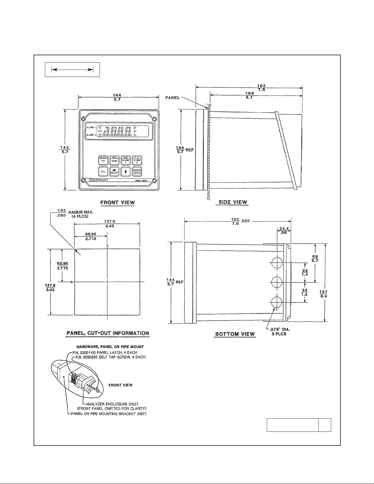
2.3.1 Panel Mounting (Standard). The Model 1054B
fits into a DIN standard 137.9 mm X 137.9 mm (5.43
in. X 5.43 in.) panel cutout. Refer to Figures 2-1 and
2-2.
1. Remove the four screws holding the front panel
assembly of the enclosure and carefully pull the
front panel and connected printed circuit boards
straight out.
2. Align the latches as shown in Figure 2-2 and
insert the analyzer enclosure through the front of
the panel cutout. Tighten the screws for a firm fit.
Do not overtighten.
3. Replace the front panel assembly. The circuit
boards must align with the slots on the inside of
the enclosure. Tighten the four front panel
screws.
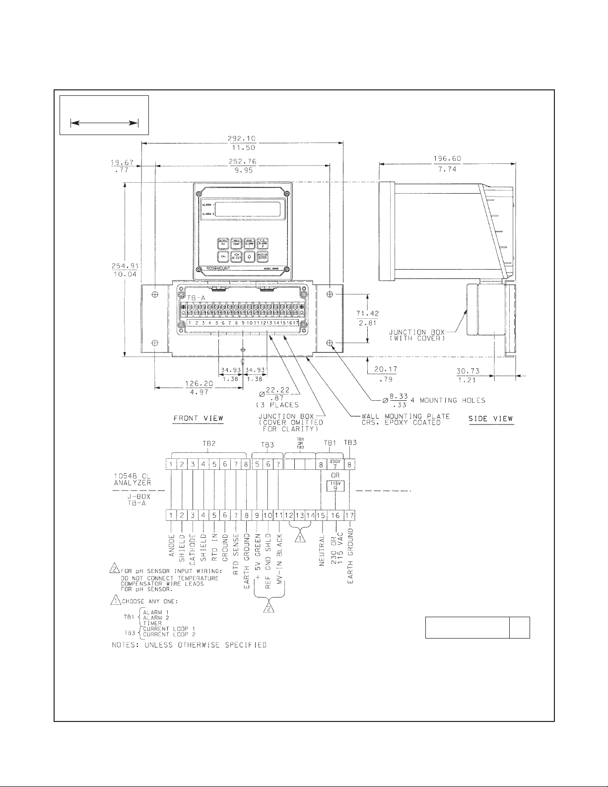
2.3.2 Wall Mounting Plate with Junction Box
(PN 23054-01). Refer to Figures 2-3 and 2-4.
1. Remove the four screws holding the front panel
assembly of the enclosure and carefully pull the
front panel and connected printed circuit boards
straight out.
2. Attach the mounting bracket to the junction box
with the hardware provided. See Figure 2-3.
Wiring can be brought to the terminal strip prior to
mounting the analyzer to the junction box.
3. Place the metal stiffener on the inside of the analyzer and install the two 1/2 in. conduit fittings
using two weather seals. Place the NEMA 4X
conduit plug in the center hole.
4. Attach the analyzer to the junction box using the
1/2 in. conduit fittings.
5. Complete the wiring connections between the
analyzer and the junction box. Refer to Figure 2-4.
Panel Mounting Section 2.3.1
Wall Mounting Section 2.3.2
Pipe Mounting Section 2.3.3
Wall Mount Enclosure Section 2.3.4
2.1 General
2.2 Unpacking and Inspection
2.3 Installation
2.4 Electrical Connections - General
2.5 Sensor Wiring
Page 11
5
MODEL 1054B CL SECTION 2.0
INSTALLATION
DWG. NO. REV.
41054B01 A
FIGURE 2-1. Panel Mounting Cutout Information
MILLIMETER
INCH
Page 12

6
Model 1054B CL SECTION 2.0
INSTALLATION
FIGURE 2-3. Wall Mounting Junction Box
Assembly
DWG. NO. REV.
41054A27 A
FIGURE 2-2. Panel Mounting Tab Installation
DWG. NO. REV.
41054A26 A
Install the mounting latches as shown (latches are
shown oversize for clarity). If the latches are not
installed exactly as shown, they will not work correctly. The screws provided are self-tapping. Tap
the screw the full depth of the mounting latch (refer
to side view) leaving a gap greater than the thickness of the cutout panel.
Page 13
7
Model 1054B CL SECTION 2.0
INSTALLATION
FIGURE 2-4. Wall Mounting Junction Box Wiring Diagram
Run the sensor wiring into the left hand opening (from front view) of the junction box. Run all other wiring out
of the right hand opening. The wiring diagram is for the most common sensors. See Figures 2-8 through 2-12
for complete wiring information.
DWG. NO. REV.
41054B39 A
WHEN INCH AND METRIC DIMS
ARE GIVEN
MILLIMETER
INCH
Page 14

8
2.3.3 Pipe Mounting (PN 23053-00). The 2 in. pipe mounting kit includes a metal plate with a cutout for the analyz-
er. Refer to Section 2.3.1 for mounting the analyzer into the plate. Mounting details are shown in Figure 2-5 (below).
MODEL 1054B CL SECTION 2.0
INSTALLATION
FIGURE 2-5. Pipe Mounting Installation
DWG. NO. REV.
41054B02 C
WHEN INCH AND METRIC DIMS
ARE GIVEN
MILLIMETER
INCH
Page 15

9
2.3.4 Wall Mount Enclosure (option -20). See Figure 2-6 (below) for installation details.
MODEL 1054B CL SECTION 2.0
INSTALLATION
FIGURE 2-6. Wall Mount Enclosure (Option -20)
DWG. NO. REV.
41054B43 A
WHEN INCH AND METRIC DIMS
ARE GIVEN
MILLIMETER
INCH
Page 16

Model 1054B CL SECTION 2.0
INSTALLATION
10
2.4 ELECTRICAL CONNECTIONS-GENERAL
All electrical connections are made to terminal blocks on the rear panel (interface board) of the analyzer. To reach
the rear panel, remove the four screws securing the back cover of the enclosure. Gently pull away the cover, which
is connected to the rear panel by a continuity wire. If the wire is disconnected for any reason, reconnect it to the
nearest mounting screw before replacing the cover.
Figure 2-7 (below) shows the interface panel and wiring connections.
FIGURE 2-7. Electrical Wiring
Wire the pH sensor to terminal block TB3 (see Figures 2-10, 2-11, and 2-12).
Wire the chlorine sensor to TB2 (see Figures 2-8 and 2-9).
DWG. NO. REV.
41054B38 A
Page 17

11
Model 1054B CL SECTION 2.0
INSTALLATION
The three openings in the bottom rear of the analyzer
housing accommodate 1/2 in. conduit fittings. Looking
at the analyzer from the rear, the right opening is for
sensor wiring, the center opening is for signal output,
and the left opening is for power, timer, and alarm
wiring. Always run sensor wiring in a separate conduit
from power wiring.
2.4.1 Power Connections. The model 1054BCL analyzer uses either 115 Vac or 230 Vac power. See
Figure 2-7 for connections. AC power wiring should be
14 gauge or greater.
2.4.2 Output Signal Wiring. Terminals 1 and 2 on TB3
are for the chlorine output signal and terminals 3 and 4
are for the pH signal. Maximum output load is 600
ohms. For best EMI/RFI protection shield the output
cable and enclose it in an earth grounded metal conduit. If the output wiring is connected directly to the
analyzer, connect the cable shield to terminal 8 on TB3.
If the output wiring runs through a junction box, connect
the cable shield to earth ground on terminal board TBA.
2.4.3 Alarm Wiring. Connect the alarm and timer circuits to terminals 1 through 6 on TB1. See Figure 2-7
for details.
CAUTION
The sensitivity and stability of the analyzer
will be impaired if the input wiring is not
grounded. DO NOT apply power to the
analyzer until all electrical connections are
verified and secure. The following precautions are a guide using UL 508 as a safeguard for personnel and property.
NOTE
The user must provide a means to disconnect the main power supply in the form of
circuit breaker or switch. The circuit breaker or the switch must be located in close
proximity to the instrument and identified
as the disconnecting device for the instrument.
1. AC connections and grounding must be in compliance with UL 508 and/or local electrical codes.
2. The metal stiffener is required to provide support
and proper electrical continuity between conduit
fittings.
3. This type 4/4X enclosure requires a conduit hub
or equivalent that provides watertight connect,
REF UL 508-26.10.
4. Watertight fittings/hubs that comply with the
requirements of UL 514B must be used.
5. Conduit hubs must be connected to the conduit
before the hub is connected to the enclosure,
REF UL 508-26.10.
6. If the metal support plate is not used, plastic fittings must be used to prevent structural damage
to the enclosure. Also, appropriate grounding lug
and AWG conductor must be used with the plastic fittings.
Page 18

12
Model 1054B CL SECTION 2.0
INSTALLATION
2.5 SENSOR WIRING
2.5.1 Chlorine Sensor.The analyzer is recommended for use with only the 499ACL chlorine sensor. Wire the sen-
sor to terminal block TB2. See Figure 2-8 for sensors having standard cable. See Figure 2-9 for sensors having
optimum EMI/RFI cable.
Sensor cable should also be shielded. If the sensor is wired directly to the analyzer, connect the outer shield of the
sensor cable to earth ground using terminal 8 on TB2. If the sensor is wired through a wall mounting junction box,
connect the outer shield to the earth ground terminal of TBA. If the outer shield of the cable is metal braid, use a
metal cable gland fitting to connect the braid to earth ground by way of the instrument case.
FIGURE 2-8. Wiring Sensor with Standard Cable to 1054B CL Analyzer
FIGURE 2-9. Wiring Sensor with Optimum EMI/RFI Cable to 1054B CL Analyzer
Page 19

13
Model 1054B CL SECTION 2.0
INSTALLATION
2.5.2 pH Sensor. Wire the pH sensor to terminal block
TB3. The table lists recommended pH sensors and the
figure number of the wiring diagram. The pH sensor
must have a preamplifier compatible with the Model
1054B.
Insulate unused leads and connect them to the cable
to prevent shorted connections.
pH Sensor Wiring Diagram
389-01-10-54 Figure 2-10
396P-01-10-54 Figure 2-11
399-07 or 399-08 Figure 2-12
FIGURE 2-10. Wiring Sensor Model 389-01-10-54 to Model 1054B CL Analyzer
FIGURE 2-11. Wiring Sensor Model 396P-01-10-54 to Model 1054B CL Analyzer
FIGURE 2-12. Wiring Sensor Model 399-07 or 399-08 to Model 1054B CL Analyzer
Page 20

14
2. Set alarm points, generate specific output currents
for testing, set zero and full-scale outputs, and calibrate concentration, pH and temperature.
3. Select temperature in °C or °F, configure alarms
(setting an alarm and configuring an alarm are different operations [see Section 4.0]), set timer
functions, establish a password, and set the current output range.
Each key in the top row of the keypad has dual functions. Pressing the key once displays the value identified by the lower (white on blue) label. Pressing the key
twice in rapid succession displays the value or activates the function identified by the upper (blue on
white) label. Two keys in the bottom row also have dual
functions. The use of these keys is explained in later
sections. Table 3-1 summarizes the values and functions associated with each key.
MODEL 1054B CL SECTION 3.0
DESCRIPTION OF CONTROLS
SECTION 3.0
DESCRIPTION OF CONTROLS
3.1 DISPLAY AND KEYBOARD FUNCTIONS. Figure 3-1
shows the front panel of the 1054B CL Microprocessor
Analyzer. The front panel consists of a single line display with information flags and an eight key membrane
keypad. Readings and instrument settings and the
mnemonics that guide the user through configuring the
instrument appear in the main display. The flags at the
sides of the display show whether an alarm relay is activated or deactivated, indicate hold and fault conditions,
and show the units of the value being displayed. As
explained in Figure 3-1 a steady flag and a flashing flag
have different meanings.
The operations of the 1054B Microprocessor Analyzer
are controlled by the eight keys shown in Figure 3-1.
The keys are used to:
1. Display values other than the primary value (PV).
Free residual chlorine concentration is the primary
value.
FIGURE 3-1. Front Panel
DWG. NO. REV.
41054B37 A
3.1 Display and Keyboard Functions
3.2 View
3.3 Edit
3.4 Configure Display
Page 21

15
Model 1054B CL SECTION 2.0
INSTALLATION
Displays the present output in mA or percent of full
scale.
Pressing SELECT with the output showing causes
the analyzer to simulate an output current
Displays the value corresponding to the low current (4 or 0 mA) output.
Pressing SELECT with the value showing allows
the value to be changed.
Displays the value corresponding to the full scale
(20 mA) output .
Pressing SELECT with the value showing allows
the value to be changed.
1. Selects a sub-menu when a mnemonic is displayed.
2. Shifts to next digit when a number is displayed.
1. Moves to the next item in the menu when a
mnemonic is displayed.
2. Pressing once increases the flashing digit by one.
3. Holding the key down autoscrolls the display.
1. Pressing key twice in rapid succession allows
access to the set function menu.
2. Enters displayed value into memory.
3. Enters displayed mnemonic into memory.
Displays Alarm 1 setpoint.
Pressing SELECT with the setpoint
showing allows the setpoint to be
changed.
Displays the concentration of free residual chlorine.
Pressing SELECT with the concentration
showing allows one point standardization
of the analyzer.
Places the analyzer in hold or removes the analyzer from hold. When the analyzer is in hold, the display shows the present chlorine concentration, but
the output remains at the value it was when hold
was initiated.
Displays the process temperature (°C or °F).
Pressing SELECT with temperature
showing allows the temperature to be
scalibrated.
Displays Alarm 2 setpoint.
Pressing SELECT with the setpoint
showing allows the setpoint to be
changed.
Display pH.
Pressing SELECT with pH showing allows the pH reading to be changed.
Pressing SCROLL (éé) with pH showing allows the automatic pH correction feature to be set
and permits the pH sensor to be calibrated.
HOLD
TEMP
OUTPUT
PV
ZERO
ALARM 1
F.S.
ALARM 2
CAL
ç
SELECT
é
ACCESS
ENTER
SECOND FUNCTION (PRESS TWICE QUICKLY)MAIN FUNCTION (PRESS ONCE)
TABLE 3-1. Description of Keys and Functions.
Page 22

16
MODEL 1054B CL SECTION 3.0
DESCRIPTION OF CONTROLS
3.2 VIEW. To view a measurement or a setting without
changing its value, press the appropriate key in the top
row. Press once to display the value of the lower label.
Press twice in rapid succession to display the value of
the upper label (see Figure 3-2).
In some cases, an information mnemonic appears
momentarily before the value is displayed. Table 3-2
explains the meaning of the information mnemonics.
TABLE 3-2. Information Mnemonics
Mnemonic Description Mnemonic Description
AdJ Adjust value LOC Access locked – enter security code
bAd Incorrect entry Pc1 Displays FRC output in percent
bF1 Buffer 1 Pc2 Displays pH output in percent
bF2 Buffer 2 PH pH display (measured process pH)
dc1 Displays FRC output value in mA FrC Free residual chlorine display
dc2 Displays pH output value in mA SEt Set mode
do1 Display output (FRC) Si1 Simulates FRC output (mA)
do2 Display output (pH) Si2 Simulates pH output (mA)
FPH Fixed pH display (manual pH input) SP1 Simulates FRC output (%)
HLd Analyzer in hold mode SP2 Simulates pH output (%)
HI1 Displays 20 mA setpoint (FRC) SLP Displays pH electrode slope
HI2 Displays 20 mA setpoint (pH) SP1 Displays Alarm 1 setpoint
itr Interval timer activated SP2 Displays Alarm 2 setpoint
LO1 Displays 0 or 4 mA setpoint (FRC) Std Standardize
LO2 Displays 0 or 4 mA setpoint (pH)
3.3 EDIT. If desired, the values accessed by the keys in
the upper row of the keypad can be edited. Use the
SELECT, SCROLL (é), SHIFT (ç), and ENTER keys
to change a displayed value. With the value to be
changed showing in the display, press SELECT. An
information mnemonic appears momentarily, then the
number reappears with the right hand digit flashing to
indicate that the number can be changed (see Figure 3-
3). Pressing the é key increases the value of the blinking digit by one unit. To move to the next digit, use the
ç key. To place the new value in memory, press
ENTER. Refer to Table 3-2 for an explanation of the
information mnemonics.
Table 3-1 summarizes the functions of the edit keys.
1. Press key.
2. AdJ shows briefly.
3. Numbers show with digit flashing.
1. Press key twice.
2. Lo shows briefly.
3. Zero point is displayed.
SELECT
ZERO
ALARM
1
FIGURE 3-3. Accessing Editing Function.
ç
FIGURE 3-2. Key Labels.
Single press of the key displays the present
free residual chlorine reading. Read only.
OUTPUT
PV
Quick double press of the key displays the
present output in mA or percent of full
scale. Read only.
Page 23

17
3.4 CONFIGURE DISPLAY. The display and analyzer
functions are configured using the set function program.
To enter the program, quickly double press the
ACCESS/ENTER key (see Figure 3-4).
Figure 4-1 on page 20 shows the main menu, the submenus, and the shorthand labels or mnemonics
assigned to each item in the menus. Table 4-2 on page
24 explains the meaning of each mnemonic. The set
function is used to configure alarms, set the interval
timer, change the units in which temperature is displayed, configure the output signal, tell the analyzer
what to do during fault or hold conditions, filter the input
signal, and set a security code.
To move through the main menu press and hold the
SCROLL (é) key. When the desired item is displayed,
release the key. Most items in the main menu have a
sub-menu associated with them. To enter a sub-menu,
press SELECT and use the SCROLL (é) key to move
through the sub-menu. To choose an item in a submenu, press SELECT. If the item selected can be edited, the screen will change to a flashing display. If digits
are showing, use the SCROLL (é) key to change number and the SHIFT (ç) key to move to the next digit.
Press ENTER to place the value in memory. If a word
or a mnemonic is flashing, indicating it can be changed
to a different mnemonic, use the SCROLL (é) key to
display the desired setting and press ENTER to place
the selection in memory.
To leave a menu or sub-menu without entering the edited value, press PV. The display will change to the concentration of free residual chlorine in the sample.
MODEL 1054B CL SECTION 3.0
DESCRIPTION OF CONTROLS
1. Press twice in rapid succession.
2. SEt appears momentarily to confirm
entry into set function menu.
3.First menu item is displayed.
Analyzer now ready to configure.
4. Use the SCROLL key to move through
the menus.
ACCESS
ENTER
SEt
in
é
FIGURE 3-4. Accessing Configuration Menus
Page 24

18
4.1 GENERAL. This section explains how to configure
the Model 1054 B CL Analyzer to a specific application.
NOTE
The analyzer is configured at the factory for
the best general use. Table 4-1 lists the factory settings. Use the worksheet (Table 4-1)
to record your configuration. The configuration can be done in any order. However, to
reduce the chance of accidentally omitting
important settings, it is best to configure the
analyzer in the order presented in the manual and on the worksheet.
4.2 MEMORY. The Model 1054B CL Analyzer can be
configured before or after installation. Configuration
settings are written into non-volatile memory and
remain in memory when power is removed.
4.3 ST ART-UP. If the sensor is not connected, the analyzer may start up flashing a fault mnemonic. The
mnemonic will be suppressed when the analyzer is in
the set function mode; however, the fault flag will continue to flash.
NOTE
To shorten sensor warmup time, wire the
sensor to the analyzer as soon as possible.
4.4 SET FUNCTION. Enter the set function by pressing the ACCESS/ENTER key twice in rapid succession. The mnemonic SEt appears momentarily, confirming that the analyzer is in the set mode. The display
then changes to the first item in the main menu, in.
NOTE
If LOC is displayed instead of SEt, the keypad is locked, and the security code must
be keyed in to gain access to the set function menus. Refer to Section 6.0.
The first three items in the menu, in, SEn, and
-O- are not used for configuring the analyzer. Instead,
selecting in displays the current being generated in the
sensor, selecting SEn allows the approximate sensitivity (current per ppm) of the sensor to be entered, and
selecting -O- sets the present current equal to zero
concentration.
Figure 4-1 is a map of the set function program. The
program contains a main menu, shown on the left hand
side of the figure, and several sub-menus connected to
items in the main menu. The menu items are identified
by mnemonics. Refer to Table 4-2 for an explanation of
each mnemonic. Selecting an item in the main menu
gives access to the associated sub-menu. For example, choosing AL1 in the main menu moves the user
into a sub-menu containing FrC, PH, and OFF. Selecting
FrC or PH in this sub-menu gives access to a deeper
sub-menu containing H-L, HYS, don, and doF. Selecting
H-L from this menu gives a mnemonic display that can
be edited (HI or LO). Selecting any other item gives a
numeric display for editing.
Model 1054B CL SECTION 4.0
CONFIGURATION
SECTION 4.0
CONFIGURATION
4.1 General
4.2 Memory
4.3 Start-Up
4.4 Set Function
4.5 Alarm 1 and 2
4.6 Interval Timer
4.7 Temperature Configuration
4.8 Current Output
4.9 Defaults
4.10 Input Filter
4.11 Alarm Setpoint
4.12 Output Scale Expansion
4.13 Simulate Current Output
4.14 pH Correction
Page 25

19
Model 1054B CL SECTION 4.0
CONFIGURATION
FACTORY SET USER SET
A. Alarm 1 Setup (
AALL11
)
1. Alarm Configuration (FrC/PH/OFF) FrC _________
2. High or Low (H-L) (Hi/Lo) Lo _________
3. Hysteresis (HYS) 0-25% 0.00 _________
4. Delay Time On (don) 0-255 sec 000 sec _________
5. Delay Time Off (doF) 0-255 sec 000 sec _________
B. Alarm 2 Setup (
AALL22
)
1. Alarm Configuration (FrC/PH/OFF/FLt) FrC _________
2. High or Low (H-L) (H
i
/Lo) Hi _________
3. Hysteresis (HYS) 0-25% 0.00% _________
4. Delay Time On (don) 0-255 sec 000 sec _________
5. Delay Time Off (doF) 0-255 sec 000 sec _________
C. Interval Timer (
iinn
t)
1. Active Status (tOn) (OFF/on) OFF _________
2. Interval Time (
i
nt) minimum 10 minutes 1 Day _________
3. Count (cnt) 1 to 60 5 _________
4. On Time (ont) 0 to 299 sec 1 sec _________
5. Off Time (OFt) 0 to 299 sec 1 sec _________
6. Duration (dur) 0 to 299 sec 2 sec _________
D. Temperature Setup (t-CC)
1. Display Temperature (d-t) (
oC/o
F)
o
C _________
2. Automatic TC (Atc) (on/oFF) on _________
Manual Temp. Value 0°C to 50°C _________
E. Current Output Setup (
OOt11//OOt22
)
1. mA Output (CUr) (020/420) 42O _________
2. Display Current Output (d-O) (Pct/doc) doc _________
3. Dampen Current Output (dPn) 0 to 255 sec 000 sec _________
F. Default Setup (
ddFF
t)
1. Relay 1 Default (rL1) (non/oFF/on) non _________
2. Relay 2 Default (rL2) (non/oFF/on) non _________
3. FrC Output Default (Cu1) (non/cur) non _________
4. PH Output Default (Cu2) (non/cur) non _________
G. Keyboard Security Setup (
CCOOdd
)
1. Keyboard Security Required 001-999 – _________
2. Keyboard Security Not Required 000 000 _________
H. Alarm Setpoints
1. Alarm 1 (SP1) 0-20 ppm or 0-14 pH 0 ppm _________
2. Alarm 2 (SP2) 0-20 ppm or 0-14 pH 20 ppm _________
I. Current Outputs
1. Zero (0 or 4 mA) (LO1/LO2) 0-20 ppm or 0-14 pH 0 ppm or 0 pH _________
2. F.S. (Full Scale) (20 mA) (HI1/ HI2) 0-20 ppm or 0-14 pH 20 ppm or 14 pH _________
TABLE 4-1. Configuration Worksheet
To move around in the main menu or in a sub-menu,
press the SCROLL (é) key. To choose an item in the
menu, press the SELECT key. If pressing SELECT
produces a flashing display, the mnemonic or number shown can be changed. Press the SCROLL (é)
and SHIFT (ç) keys to change a number; press the
SCROLL (é) key to change a mnemonic. To place
the value in memory, press ENTER. After an edited
value has been stored, the display returns to the item
in the sub-menu that allowed access to the value. For
example, selecting HYS from the sub-menu attached
to AL1, allows access to a number whose value can
be changed. After the number has been edited and
stored in memory, the display returns to HYS.
Page 26

20
Model 1054B CL SECTION 4.0
CONFIGURATION
FIGURE 4-1. Set Function Menu
FrC
PH
*
OFF
SEt
rL1
rL2
Cu1
Cu2*
SHO
FrC
PH
*
FLt
OFF
d-t
Atc
in
SEn
-0-
AL1
AL2
Int
t-C
Ftr
Ot1
Ot2
dFt
UEr
dtS
COd
dPn
CUr
d-O
oFF
on
doc
Pct
on
oFF
non
non
cur
on
oFF
420
020
oo
F
oo
C
tOn
int
cnt
ont
OFt
dur
tiL
SEC
uin
hr
dAY
* Not available unless the optional
pH board has been installed
H-L
HYS
don
doF
Hi
Lo
Page 27

21
Model 1054B CL SECTION 4.0
CONFIGURATION
AL1 Alarm 1 setup
AL2 Alarm 2 setup
APH Automatic pH adjustment
Atc Automatic temperature compensation
o
C Temperature °C
COd Security code
cnt Timer count
CUr Configure current output
Cu1 Configure fault output 1 (FRC)
Cu2 Configure fault output 2 (pH)
cur Default current setpoint
dAY Days
dFt Fault configuration
d-O Display output
d-t Display temperature
doc Display output in mA
doF Relay delay off time
don Relay delay on time
dPn Dampen outputs
dtS LCD/LED display test
dur Timer duration
°o
F Temperature °F
FLt Use alarm as fault alarm
Hi Relay action – high
H-L Alarm logic
hr Hours
HYS Hysteresis
in Sensor input current
int Interval period
Int Timer setup
Lo Relay action – low
non No action on fault
not pH CPU PCB not installed
OFF Alarm not used
oFF Function off
ont Timer on time
On Use alarm as process alarm
on Function on
OFt Timer off time
Ot1 Configure output 1 (FRC)
Ot2 Configure output 2 (pH)
Pct Display output in percent
rL1 Relay 1 fault setup
rL2 Relay 2 fault setup
SEC Seconds
SHO Show fault history
t-C Temperature configuration
ti L Timer – time remaining
tOn Timer status
UEr Software version
uin Minutes
420 4mA to 20mA output
020 0mA to 20mA output
-0- Zero sensor
TABLE 4-2.
Set Function Mnemonics
Page 28

22
4.5 ALARM 1 AND 2. The alarms can be configured to
perform on - off process control. Selecting AL1 or AL2
allows alarm 1 or alarm 2, respectively, to be configured.
A. Alarm for Free Residual Chlorine. Select FrC if the
alarm is to monitor the concentration of free residual
chlorine. See steps E through H for further alarm configuration.
B. Alarm for pH. Select PH if the alarm is to monitor
pH. See steps E through H for further alarm configuration.
C. Fault (Alarm 2 Only). Selecting FLt makes Alarm 2
a fault alarm. Relay 2 energizes when the analyzer
senses a fault condition.
D. Off. Select OFF if the alarm is not to be used or to
temporarily disable the alarm. Alarm setpoints will display oFF if this item is selected.
E. Alarm Logic. Select H-L to set high or low alarm
logic. Hi activates the alarm when the reading is
greater than the setpoint value. Lo activates the alarm
when the reading is less than the setpoint value.
F. Relay Hysteresis. Select HYS to set the hysteresis or
dead band. Hysteresis is the difference between the
alarm setpoint and the reading past the setpoint at
which the relay deactivates. Hysteresis may be set
between 0 and 25% of the setpoint. Use hysteresis
when a specific chlorine concentration should be
reached before the alarm deactivates.
Model 1054B CL SECTION 4.0
CONFIGURATION
G. Delay On Time. Select don to set the delay on time.
Delay on time is the time between an alarm setpoint
being reached and the relay activating. The delay may
be set between 0 and 255 seconds. An alarm state
restarts the time from zero.
H. Delay Off Time. Select doF to set the delay off time.
Delay off time is the time between an alarm setpoint
being cleared and a relay deactivating. The delay may
be set between 0 and 255 seconds. An alarm state
restarts the time from zero.
4.5.1 Alarm Setup (
AALL11/AALL22
). Refer to Figure 4-2.
1. Enter the set function menu by double pressing
the ACCESS/ENTER key.
2. SCROLL (é) until AL1 or AL2 appears in the display.
3. Press SELECT to move into the sub-menu. FrC, PH,
OFF, or FLt (Alarm 2 only) will be displayed.
4. SCROLL (é) until the desired item appears, then
press SELECT.
5. If OFF was selected, the display will show oFf.
Press the ENTER key to return to AL1 or AL2
(whichever alarm was being configured). Skip to
Step 1 1.
If FrC or PH was selected, the display will show
FrC or PH momentarily, then change to H-L. Go to
Step 6.
If FLt was selected, the display will show FLt.
Press the ENTER key to return to AL2. Go to Step 11.
6. With H-L showing in the display, press SELECT.
Hi or Lo will appear as a flashing display.
7. SCROLL (é) to the desired setting and press
ENTER to store the setting in memory. The display will return to H-L. To make changes to the
relay activation logic, proceed to Step 8, otherwise go to Step 11.
8. SCROLL (é ) to display HYS, don, or doF then
SELECT the desired item. A flashing numeric display will appear, indicating that a number is
required.
9. Use the SCROLL (é) and SHIFT (ç ) keys to
change the display to the desired value.
10. Press ENTER to store the value in memory. The
analyzer will acknowledge, and the display will return
to the mnemonic that permitted access to the value.
Repeat Step 8 if further changes are desired.
11. Repeat Steps 3 through 10 to configure the other
alarm.
12. To return to the top menu of the set function
menu, press the ACCESS/ENTER key.
FrC
PH
OFF
FrC
PH
FLt
OFF
in
AL1
AL2
H-L
HYS
don
doF
Hi
Lo
SEt
Figure 4-2. Alarm 1 and Alarm 2 Setup.
Page 29

23
4.6 INTERVAL TIMER. Select Int to set the interval
timer relay logic. The timer can be used to activate
and control a sensor cleaner. Refer to Figure 4-3 for an
explanation of the terms used.
A. Interval Timer Enable/Disable. Select t
On
to
enable the interval cycle (on) or disable the interval
cycle (OFF).
B. Interval Period. Select int to set the amount of
time between control cycles (see Figure 4-3). int
opens a sub-menu that asks for time in SEC for seconds, uin for minutes, hr for hours, and dAY for days.
The recommended minimum interval is 10 minutes.
C. Relay Activations Per Cycle. Select cnt to enter
the number of times the relay activates per cycle. The
range is 1 to 60.
D. Relay Activation Duration. Select ont to enter the
amount of time the relay remains on each time it activates. The range is 0.1 to 299.9 seconds.
E. Relay Deactivation Duration. Select OFt to set the
amount of time the relay remains deactivated between
each on-period during the cycle. Deactivation time is
valid only when cnt is 2 or greater. The range is 0.1 to
299.9 seconds.
F. Sensor Recovery Time. Select dur to set the
length of time between the end of the last on-period
and the end of the control cycle. The recovery time
gives the sensor time to restabilize before the analyzer returns to on-line operation. Recovery time may be
set between 0 and 299 seconds.
G. Interval Time Remaining. Select tiL to display the
time remaining before the next cycle starts. If tiL is
selected during the control cycle, display will show --.
NOTE
The Model 1054B CL is placed on HOLD
during the control cycle (from first on-period
through the sensor recovery time). The analyzer simulates a fault condition and briefly
shows itr every eight seconds. The display
continues to show the measured value.
Model 1054B CL SECTION 4.0
CONFIGURATION
4.6.1 Interval Timer Set Up (Int). Refer to Figure 4-4.
1. Enter the set function menu by double pressing
the ACCESS/ENTER key.
2. SCROLL (é) until Int appears in the display.
3. Press SELECT to move to the next menu level. The
display will show tOn. Press the SELECT key again.
4. SCROLL (é ) to display on or OFF and press
ENTER to store the desired setting in memory. If
the interval timer was selected, go to Step 5, otherwise go to Step 10.
5. Press the SCROLL (é) key once to display int,
then press the SELECT key. The display will
change to SEC. SCROLL (é) until the desired
unit, minutes (uin) hours (hr), or days (dAY)
appears in the display. Press SELECT. The display will change to a numeric value with the right
hand digit flashing.
6. Use the SCROLL (é) and the SHIFT (ç) keys
to change the displayed number to the desired
value. ENTER the number into memory.
7. Repeat steps 5 and 6 if needed. For example, if the
desired interval is 6.5 hours, enter 30 uin and 6 hr.
8. Press the ENTER key again to return to the main
timer menu. SCROLL (é) to the next desired
item and press SELECT.
9. Selecting any of the remaining menu items (cnt,
ont, OFt, and dur) causes the display to show a
numeric value. Use the SCROLL (é) and SHIFT
(ç) keys to change the displayed number to the
desired value and ENTER the new value into
memory. Continue until all the settings have been
made.
10. Press the ENTER key to return to the main menu.
RELAY
ON
RELAY
OFF
TIME
int
ont
OFt
ont
dur
cnt = 2
SEt
OFF
on
tOn
int
cnt
ont
OFt
dur
tiL
SEC
uin
hr
dAY
in
Int
Figure 4-3. Timer Diagram for One Cycle
Figure 4-4. Interval Timer Setup
Page 30

24
4.7 TEMPERATURE CONFIGURATION. Select t-C
for temperature reading and compensation choices.
A. Temperature Display. Select d-t to display tem-
perature in °C or °F.
B. Automatic Temperature Compensation. Select
Atc to enable or disable automatic temperature compensation. The 1054B CL Analyzer uses a membranecovered amperometric sensor. Because the permeability of the membrane increases about 3%/°C, temperature compensation is critical if the measurement and
calibration temperatures are different. When on is
selected, the analyzer uses the temperature input from
the sensor for temperature compensation. When oFF is
selected, the analyzer uses the value entered by the
user. Turning off the automatic temperature compensation, i.e., placing the analyzer in manual temperature
compensation, is useful only if the temperature sensor
is faulty and the calibration and measurement temperatures differ by at most 1 or 2 °C. Selecting oFF disables temperature specific fault messages (refer to
Section 8.1).
4.7.1 Temperature Setup (t
--CC
). Refer to Figure 4-5.
1. Enter the set function menu by double pressing the
ACCESS/ENTER key .
2. SCROLL (é) until t-C appears in the display.
3. Press SELECT to move to the next menu level.
d-t will show the display.
4. SCROLL (é ) to display desired item, then
SELECT it.
5. If d-t is selected, the display will flash oC or oF.
SCROLL (é) until the desired unit appears in the
display. Press ENTER to store the selection into
memory . The display will return to d-t.
6. If At c is selected, the display will flash on or oFF.
SCROLL (é) and ENTER the desired temperature
compensation into memory. Choosing on causes the
display to return to At c. Choosing oFF causes a
flashing number to be displayed. Use the
SCROLL (é) and SHIFT (ç) keys to change the
display to the desired temperature and press
ENTER. The display returns to Atc.
7. Press the ENTER key to return to the main menu.
4.8 CURRENT OUTPUT. Select Ot1 to configure the
current output for free residual chlorine. Select Ot2 to
configure the output for pH. Note that Ot2 is available
only if the pH board has been installed. See Figure 4-6.
A. Output Dampening. Select dPn to dampen the analyz-
er output. Dampening reduces the apparent noise but
increases the response time of the output. The dampening
feature averages the signal for a set period of time
(between 0 and 255 seconds) and changes the output by
an amount equal to 63% of change between the present
and previous sampling period.
B. mA Output Range. Select CUr to set the output sig-
nal to 0-20 mA (020) or to 4-20 mA (420).
C. Display Output. Select d-O to display the output in
mA (doc) or in percent of full scale (Pct).
4.8.1 Output Setup (
OOt11/OOt22
). Refer to Figure 4-6.
1.
Enter the set function menu by double pressing the
ACCESS/
ENTER
key .
2. SCROLL (é) until Ot1 appears in the display.
3. Press SELECT to move to the next menu level.
dPn will displayed.
4. SCROLL (é) then SELECT desired item.
5.
If dPn is selected, a numeric display will flash to indicate that a value is required. Use the
SCROLL (é)
and SHIFT (ç) keys to change the display to the
desired value. Press ENTER to place the value in
memory.
Model 1054B CL SECTION 4.0
CONFIGURATION
in
t-C
SEt
in
Ot1
Ot2
SEt
d-t
AtC
on
oFF
o
F
o
C
doc
Pc
t
420
020
dPn
CUr
d-O
Figure 4-5. Temperature Configuration Setup
Figure 4-6. Current Output Setup
Page 31

25
Model 1054B CL SECTION 4.0
CONFIGURATION
SEt
in
dFt
6. If CUr or d-O is selected, SCROLL (é ) to the
desired mnemonic and press ENTER to store it in
memory.
7. Press ENTER to return to the main menu and
SCROLL (é ) until Ot2 shows in the display.
Repeat steps 5 and 6 to configure the pH output.
Ot2 is available only if the pH correction board
has been installed in the analyzer.
8. Press the ENTER key to return to the main
menu.
4.9 DEFAULTS. Select dFt to configure default set-
tings during faults or hold status. See Table 8-1 for a
listing of the fault conditions that can be diagnosed by
the analyzer.
A. Relay 1 and 2. rL1 is relay 1 and rL2 is relay 2.
The relays can be set to activate (on), deactivate
(oFF), or hold present status (non). Table 4-3 describes
how to configure the relays for various fault or hold
conditions. For example, for relay 1 to activate when
the analyzer is in hold, both alarm 1 and relay 1 must
be on.
B. Current Output. Cu1 sets the value to which the
current at output 1 goes and Cu2 sets the value to
which the current at output 2 goes when the analyzer
is in hold or senses a fault. To hold the output current
at the last process value, choose non. To send the output current to a specified value, chose cur; cur is
probably the better choice.
C. Fault History. Selecting SHO causes all the faults
detected during the most recent event to be displayed
one at a time. Several faults occurring at the same
time are considered to be one fault event. To view the
previous fault event, press the SCROLL (é) key. To
clear the SHO history, press ENTER.
4.9.1 Default Setup (
ddFF
t). Refer to Figure 4-7.
1. Enter the set function menu by double pressing
the ACCESS/ENTER key.
2. SCROLL (é) until dFt appears in the display.
3. Press SELECT to move to the next menu level.
rL1 will show in the display.
4. To set default relay 1, SELECT rL1.
5. SCROLL (é ) to on, oFF, or non, and press
SELECT to enter the desired mnemonic.
6. Repeat Steps 4 and 5 for relay 2.
7. To set the default current for output 1, SCROLL
(é) to Cu1 and SELECT it.
8. SELECT non or cur. Choosing cur causes the
display to change to a flashing number. Use the
SCROLL (é) and SHIFT (ç) keys to change
the display to the desired value. Press ENTER to
place the value in memory.
9. To set the default current for output 2, repeat
steps 7 and 8.
10. Press the ENTER key to return to the main
menu.
ANALYZER CONDITION
NORMAL HOLD FAULT
AL1/AL2 setting AL1/AL2 setting AL1/AL2 setting
On OFF FLt On OFF FLt On OFF FLt
(Alarm 2 (Alarm 2 (Alarm 2
only) only) only)
on PV dtmns – – + – – + – +
oFF PV dtmns – – – – – – – +
non PV dtmns – – PV dtmns – – PV dtmns – +
Default
setting
rL1/rL2
PV dtmns : Process value determines the alarm state.
+ : means the relay activates
– : means the relay does not activate
TABLE 4-3. Relay States for Various Analyzer Conditions and Alarm/Default Configurations
on
oFF
non
FIGURE 4-7. Default Setup
non
cur
rL1
rL2
Cu1
Cu2
SHO
Page 32

26
4.10 INPUT FILTER. The input filter (Ftr) compen-
sates for noise by averaging a given number samples
of the input signal. Increasing the sample number
reduces noise but increases the response time (see
Section 7.1 for more information).
4.10.1 Filter Response Setting.
1. Enter the set function menu by double pressing the
ACCESS/ENTER key.
2. SCROLL (é) until Ftr appears in the display.
3. Press SELECT. A numeric display appears with
the right hand digit flashing.
4. Use the SCROLL (é) and SHIFT (ç) keys to
change the display to the desired number of samples.
5. Press ENTER to place the number in memory.
4.11 ALARM SETPOINT. Configure the analyzer as
described in sections 4.5 through 4.10 before
programming the alarm setpoints. Refer to
Figure 4-8.
1. Press the PV key to ensure the analyzer is not in
the set function menu.
2. Press the ZERO/ALARM 1 or F.S./ALARM 2 key.
SP1 for alarm 1 or SP2 for alarm 2 will show briefly,
followed by the present alarm setpoint.
NOTE
If the alarm was set to OFF or, in the
case of alarm 2, to FAULT during configuration, the analyzer will display oFF
or FLt respectively when the ALARM
key is pressed.
3. To change the alarm setpoint, press SELECT.
AdJ will show briefly followed by a numeric display with right hand digit flashing.
4. Use the SCROLL (é) and SHIFT (ç) keys to
change the display to the desired setpoint.
5. Press ENTER to place the new value in memory.
The display will show SP1 (or SP2) briefly followed
by the new setpoint.
6. To program the second alarm setpoint repeat
Steps 2 through 5.
NOTE
Relays are normally open (N.O.), but they can
be changed to normally closed (N.C.). Locate
the relay to be changed. K1 is relay 1, K2 is
relay 2, and K3 is relay 3. For the relay selected,
cut the conductor at the bowtie on the reverse
side of the power supply board. For relay 1, solder a jumper between the center terminal and
W4. For relay 2, solder a jumper between the
center terminal and W6. For relay 3, solder a
jumper between the center terminal and W8.
ACCESS
ENTER
ZERO
ALARM
1
F.S.
ALARM
2
é
ç
SELECT
ç
SELECT
Press
Once
Press
Once
Displays
Briefly
Displays
Briefly
Numeric
Display
Change to
desired
value
Press
Once
Numeric
Display
of
Setpoint
FIGURE 4-8. Alarm Setpoint
Model 1054B CL SECTION 4.0
CONFIGURATION
AdJ
SP1/SP2
SP1/SP2
Displays
Briefly
Page 33

27
B. Full Scale Setpoint. The full scale setpoint is the
reading that produces a 20 mA output. Hi1 identifies
the full scale for output 1, and Hi2 identifies the full
scale setpoint for output 2. For an analyzer equipped
with automatic pH compensation, output 1 is chlorine
and output 2 is pH.
1. Press the PV key to ensure that the analyzer is
not in the set function menu.
2. Quickly double press the F.S./ALARM2 key. HI1
or HI2 will show briefly in the display, followed by
the present full scale setpoint for the output
selected. To switch outputs, press the
F.S./ALARM2 key twice again and the display will
toggle to the other output.
3. To change the setpoint, press the SELECT key.
The display will acknowledge briefly with AdJ followed by a numeric display with the right hand
digit flashing.
4. Use the SCROLL (é) and SHIFT (ç ) keys to
display the desired setpoint.
5. Press ENTER to place the new value in memory.
The display will show HI1 or HI2 briefly followed
by the new zero setpoint.
6. If the analyzer has two setpoints, repeat steps
2 through 5 to program the full scale setpoint for
the second output.
NOTE
For reverse output, enter the higher
concentration or pH for zero and the
lower concentration or pH for full scale.
4.12 OUTPUT SCALE EXPANSION. Configure the
analyzer as described in Sections 4.5 through 4.10
before programming the zero and full scale setpoints.
Refer to Figure 4-9.
A. Zero Setpoint. The zero setpoint is the reading that
produces a 0 or 4mA output (depending on how the
output was configured). LO1 identifies the zero setpoint
for output 1, and LO2 identifies the zero setpoint for
output 2. For analyzers equipped with automatic pH
compensation, output 1 is chlorine and output 2 is pH.
1. Press the PV key to ensure the analyzer is not in
the set function menu.
2. Quickly double press the ZERO/ALARM1 key.
LO1 or LO2 will show briefly in the display, followed
by the present zero setpoint for the output selected. To switch outputs, press the ZERO/ALARM1
key twice again and the display will toggle to the
other output.
3. To change the setpoint, press the SELECT key.
The display will acknowledge briefly with AdJ followed by a numeric display with the right hand
digit flashing.
4. Use the SCROLL (é) and SHIFT (ç) keys to
change the display to the desired value.
5. Press ENTER to place the new value in memory.
The display will show LO1 or LO2 briefly followed by
the new zero setpoint.
6. If the analyzer has two outputs, repeat steps 2
through 5 to program the zero setpoint for the
second output.
ACCESS
ENTER
ZERO
ALARM
1
F.S.
ALARM
2
é
ç
SELECT
ç
SELECT
Press
Twice
Press
Once
Displays
Briefly
Displays
Briefly
Numeric
Display
Change to
desired
value
Press
Once
Numeric
Display
of
Output
FIGURE 4-9. Output Scale Expansion
AdJ
LO1/LO2
HI1/H
I2
Model 1054B CL SECTION 4.0
CONFIGURATION
LO1/LO2
HI1/H
I2
Displays
Briefly
Page 34

28
4.13 SIMULATE CURRENT OUTPUT. The analyzer
can provide a simulated output to check the operation
of pumps, valves, and recorders. The output can be in
current (dO1) or in percent of full scale (Pc1). The output configuration programmed in Section 4.9 determines which mnemonic appears. If the analyzer has
dual outputs, i.e., the pH correction board has been
installed, a simulated signal can be generated at both
outputs. Pc1 or dO1 identifies output 1 (free residual
chlorine), and Pc2 or dO2 identifies output 2 (pH). Refer
to Figure 4-10.
A. Simulate Output in Percent. The simulated output
will be in percent full scale if Ot1 or Ot2 in Section 4.8
was configured to display percent (Pct).
1. Press the PV key once to ensure that the analyzer
is not in the set function menu.
2. Quickly double press the OUTPUT/PV key. Pc1
or Pc2 will show briefly in the display, then the
display will change to the last simulated output. If
the analyzer has dual outputs and the wrong output is displayed, double press the OUTPUT/PV
key a second time. The display will toggle to the
other output.
3. To make the analyzer generate the simulated output, press the SELECT key. SP1 or SP2,
depending on which output was selected in step
2, will appear momentarily, followed by a numeric
display with the right hand digit flashing.
4. To change the simulated output to a different
value, use the SCROLL (é) and SHIFT (ç )
keys.
5. Press ENTER to store the new value in memory.
The display will briefly show Pc1 or Pc2 followed
by the entered value. Because the analyzer is in
hold while the simulated current is being generated, the display flashes and the mnemonic HLd
appears occasionally. After one minute the display returns to the measured value (flashing), the
hold flag remains on, and the output remains at
the simulated value. The relays will operate as
programmed in Section 4.9.
6. To end the simulated output and remove the analyzer from hold, quickly double press the
HOLD/TEMP key. The display stops flashing, the
hold flag turns off, and the output returns to the
value determined by the scale expansion programmed in Section 4.12.
B. Simulate Output in Current. The simulated output
will be in mA if Ot1 or Ot2 in Section 4.8 was configured to display current (doc).
1. Press the PV key once to ensure that the analyzer is not in the set function menu.
2. Quickly double press the OUTPUT/PV key. dO1
or dO2 will show briefly in the display, then the display will change to the last simulated output. If the
analyzer has dual outputs and the wrong output is
displayed, double press the OUTPUT/PV key a
second time. The display will toggle to the other
output.
Model 1054B CL SECTION 4.0
CONFIGURATION
ACCESS
ENTER
OUTPUT
PV
é
ç
SELECT
ç
SELECT
Press
Twice
Press
Once
Displays
Briefly
Displays
Briefly
Numeric
Display
Change to
desired
value
Press
Once
FIGURE 4-10. Simulate Current Output
Si1/Si2
SP1/SP2
dO1/dO2
Pc1/Pc2
Numeric
Display of
Output
dO1/dO2
Pc1/Pc2
Displays
Briefly
Page 35

Model 1054B CL SECTION 4.0
CONFIGURATION
3. To change the simulated output, press the
SELECT key. Si1 or Si2, depending on which out-
put was selected in step 2, will appear momentarily, followed by a numeric display with the right
hand digit blinking.
4. To change the simulated output to a different
value, use the SCROLL (é) and SHIFT (ç )
keys.
5. Press ENTER to store value in memory. The display will briefly show dO1 or do2 followed by the
entered value. Because the analyzer is in hold
while the simulated current is being generated,
the display flashes and the mnemonic HLd
appears occasionally. After one minute the display returns to the measured value (flashing), the
hold flag remains on, and the output remains at
the simulated value. The relays will operate as
programmed in Section 4.9.
6. To end the simulated output and remove the analyzer from hold, quickly double press the
HOLD/TEMP key. The display stops flashing, the
hold flag turns off, and the output returns to the
value determined by the scale expansion programmed in Section 4.12.
4.14 pH CORRECTION. Free residual chlorine is the
sum of hypochlorous acid and hypochlorite ion. The
fraction of each species present is determined by the
pH. Because the sensor responds only to hypochlorous acid, a pH correction is necessary to convert sensor response into the total concentration of free
chlorine. The analyzer permits either automatic or
manual pH correction. In automatic pH correction, the
analyzer uses the measured pH of the sample to calculate the total concentration of free chlorine. In manual pH correction, the user keys in the sample pH.
A. Analyzer Equipped with Automatic pH
Correction. Select on to enable and select oFF to dis-
able automatic pH correction. If automatic pH correction is disabled, a manual pH value must be entered.
The analyzer uses the entered value for the correction.
1. Press the PV key to ensure that the analyzer is
not in the set function menu.
2. Press CAL. The display will show PH momentarily
followed by the present pH.
29
3. SCROLL (é) until APH appears in the display,
then press SELECT. The display will be flashing
either on or oFF.
4. Press SCROLL (é) until the desired mnemonic
appears in the display. Press ENTER to place the
selection in memory.
5. If on was selected, mnemonic PH appears momentarily, and the display returns to the current pH
value.
6. Press the PV key to return the display to the chlorine reading.
7. If oFF was selected, the mnemonic FPH appears
followed by a number. Press SELECT. AdJ
appears momentarily followed by a number with
the right hand digit flashing. Use the SCROLL
(é) and SHIFT (ç) keys to change the display
to the desired pH value. Press ENTER to store
the value in memory. FPH appears momentarily,
and the entered number reappears in the display.
The analyzer will use the pH value entered in this
step for future pH corrections.
8. Press the PV key to return the display to the chlorine reading.
B. Analyzer Without pH Correction. The analyzer
uses the pH value entered in this step for all
corrections.
1. Press the PV key to ensure that the analyzer is
not set in the set function menu.
2. Press CAL. The display will show FPH momentarily followed by a number.
3. Press SELECT. AdJ will appear momentarily followed by a number with the right hand digit flashing. Use the SCROLL (é) and SHIFT (ç) keys
to change the display to the desired pH value.
Press ENTER to store the value in memory. FPH
appears momentarily, and the entered number
reappears in the display.
4. Press the PV key to return the display to the chlorine reading.
Page 36

30
If the temperature reading from the analyzer does not
agree with the standard thermometer, adjust the analyzer temperature display.
1. Press the PV key to ensure that the analyzer is
not in the set function menu.
2. Press the TEMP key once. The display will briefly
show °F or °C followed by the present temperature
in either °F or °C (depending on the units selected in Section 4.7).
3. Press the SELECT key. AdJ will show briefly followed by a numeric display with the right hand digit
flashing.
4. Use the SCROLL (é) and SHIFT (ç ) keys to
change the display to the correct value.
5. Press ENTER to place the new value in memory.
°F or °C shows briefly followed by the corrected
temperature.
Temperature calibration can be done without removing
the sensor from the process stream. To ensure that
the reference instrument and the 499A CL sensor are
measuring the same sample temperature, install the
reference thermowell as close to the sensor as possible. If a thermowell is not available, measure the temperature of the process at a sample tap. Let a sample
of the process stream, taken from a point as close to
the sensor as possible, discharge into the bottom of a
small container. To minimize heat exchange between
the sample and the ambient air, let the sample flow as
rapidly as possible. Place the reference temperature
sensor in the container so that it is completely bathed
in the sample. Allow adequate time for equilibration
and compare the analyzer temperature reading with
the reference temperature. Adjust the analyzer reading if necessary.
5.3.2 Analyzer Zero. The analyzer/sensor loop must be
zeroed every time a new sensor is place in service or an
existing sensor is rebuilt. Rebuilding a sensor means
replacing the membrane and/or replenishing the electrolyte. Zero the loop by placing the sensor in chlorinefree water, and allow it to operate until the current
reaches a minimum value. The minimum current is
called the residual current.
Model 1054B CL SECTION 5.0
START-UP AND CALIBRATION
SECTION 5.0
START-UP AND CALIBRATION
5.1 GENERAL. This section gives the start-up and cali-
bration procedures for the Model 1054B CL Analyzer
with the Model 499A CL sensor and, if appropriate, a
Model 389, 396P, or 399 pH sensor.
5.2 START-UP. When the analyzer is powered up, a
polarization voltage is applied between the anode and
cathode. The sensor current is initially very high but
then falls off quickly and usually reaches a steady
state after a few hours.
5.3 CALIBRATION.
This section describes how to do the following:
1. calibrate the temperature response of the
chlorine sensor;
2. zero the chlorine sensor;
3. calibrate the chlorine sensor against a grab
sample or a known standard
4. calibrate the pH sensor.
5.3.1 Temperature Standardization. The 1054B CL
analyzer uses a membrane-covered amperometric sensor. Because the permeability of the membrane is a
strong function of temperature, accurate temperature
measurement is necessary for accurate chlorine measurements. The 499A CL sensor measures temperature
using a 100 ohm platinum RTD. The accuracy of a new
sensor/analyzer loop is about ±1°C, which is adequate
for most applications. A new sensor seldom requires
temperature calibration. If ±1°C accuracy is not acceptable or if the temperature measurement is suspected of
being in error, use the following procedure to calibrate
the RTD.
1. Immerse the sensor in a container of water to at
least an inch from the bottom of the lower threads.
If the temperature of the water is appreciably different from ambient, use an insulated container.
2. Place a calibrated thermometer in the water with
the sensor.
3. Stir the water continuously.
4. Allow temperature readings to stabilize. The stabilization step may take as long as 30 minutes.
5.1 General
5.2 Start-Up
5.3 Calibration
Page 37

31
Model 1054B CL SECTION 5.0
START-UP AND CALIBRATION
1. Place the sensor in a container of fresh distilled or
deionized water. Immerse the sensor to at least an
inch from the bottom of the lower threads. Add 4 to 6
mL of pH 7 buffer for every 1000 mL of water. If pH 7
buffer is not available, add about 0.50 gram of a neutral salt, like sodium chloride or potassium chloride,
to the water. The buffer or salt increases the ionic
concentration of the water and reduces the rate of
loss of electrolyte through the sensor membrane.
2. Allow the sensor to stabilize. The stabilization time
may be as long as 4 hours. Periodically measure
the current while the sensor is stabilizing. To view
the current, quickly double press the ACCESS/
ENTER key. Set will be displayed momentarily, then
the display will change to in. Press the SELECT
key to display the current.
NOTE
The sensor current and, therefore, the displayed concentration will fluctuate and may
even become negative while the loop is zeroing.
3. Once the current is stable, press the
ACCESS/ENTER key twice to return to the top of the
main menu.
4. Press the SCROLL (é) key until -O- is displayed.
5. Press the SELECT key. -O- will flash for about five
seconds and then freeze. The analyzer loop is
now zeroed.
6. Press the PV key to leave the set function menu.
The analyzer should read near zero ppm.
5.3.3 Calibrating the Chlorine Sensor Against a
Grab Sample. The chlorine sensor can be calibrated
against a grab sample taken from the process stream.
Observe the following precautions:
1. Calibrate the pH sensor before starting the grab
sample calibration. See Sections 5.3.5, 5.3.6, and
5.3.7. If automatic pH correction is not being used,
measure the pH of the process stream and enter
the value before starting the calibration. See
Section 4.14.
2. Ensure that the grab sample is representative of
the liquid flowing past the senor. Take the sample
from the process stream at a point as close to the
sensor as possible.
3. The sensor requires continuous flow of liquid past
it. Place the sample valve downstream from the
sensor to avoid starving the sensor when taking
the sample.
4. Flush the sample line thoroughly then rinse the
sample bottle several times before sampling.
Because aqueous solutions of free chlorine
decompose rapidly in light, collect the sample in a
colored glass bottle.
5. Glassware used for sampling may have a chlorine demand. Before taking the sample, soak the
sample bottle for several days in a solution of
dilute chlorine (20 drops of bleach in one liter of
water) and rinse thoroughly. Check the bottle for
residual chlorine before using it for samples.
6. Aqueous solutions of free chlorine are unstable.
Start the analysis immediately after collecting the
sample. See Standard Methods
, 19th edition,
4500-CI for appropriate analytical methods.
To calibrate the sensor follow the steps below:
1. Wait until the analyzer reading is stable or drifting
slowly. Note the reading and take the sample.
NOTE
For best results calibrate the sensor
when the chlorine level in the process
stream is at the high end of the normal operating range. Ideally, the
senor current should be at least 70
nanoamps when the senor is calibrated. If the pH of the process stream is
high and the chlorine levels are low,
the sensor current might be too low
for an accurate calibration.
2. Immediately measure the free residual chlorine
concentration in the sample.
3. Note the present concentration of chlorine in the
sample stream. Be sure the concentration is stable. Calculate the calibration value using the following formula:
C = (X/Y) (A)
where C is the calibration value to be entered, X
is the present analyzer reading, Y is the analyzer
reading at the time the grab sample was taken,
and A is the concentration of free residual chlorine in the grab sample.
4. Enter the calibration value:
A. Press the PV key to make sure the analyzer
is not in the set function menu.
Page 38

32
B. Press the SELECT key. Std appears momen-
tarily, then the display changes to the last
free chlorine reading. The right hand digit will
be flashing.
C. Use the SCROLL (é) and SHIFT (ç) keys
to change the display to the value calculated
in step 3.
D. Press the ENTER key to place the calibra-
tion value in memory. The analyzer is now
standardized.
5.3.4 Calibration Against a Known Standard. If calibration against a grab sample is not feasible, the loop
can be calibrated against a solution containing a
known concentration of chlorine.
1. The procedure requires that pH be known. If
automatic pH correction is being used, calibrate
the pH sensor following the procedure in Section
5.3.6 before starting. If automatic pH correction is
not being used, obtain and calibrate a pH meter
and sensor.
2. Pour about 900 mL of process water into a 1-liter
beaker. Place the chlorine and pH sensors in the
beaker. Place a magnetic string bar in the beaker
and begin stirring. Adjust the stirring speed until
the chlorine reading is essentially independent of
stirring speed. Do not stir so fast that a vortex
appears. A thin sheet of plastic foam placed
between the stirrer and the beaker will insulate
the liquid from the heat generated by the stirrer.
3. Using household bleach, adjust the chlorine level
until it is at the high end of the normal operating
range. Bleach contains about 45,000 ppm chlorine (as Cl2). Adding 0.05 mL of bleach (one
drop) to 1000 mL of sample increases the chlorine level about 2 ppm. To increase the chlorine
level by a smaller amount, dilute the bleach
before adding it to the sample.
4. Monitor the temperature, pH, and the chlorine
reading until all are stable or drifting slowly. If
manual pH correction is being used, enter the pH
value. Note the analyzer reading and immediately
remove a sample of the standard solution for
analysis. Determine the concentration of free
chlorine in the sample. Aqueous solutions of free
chlorine are unstable. Start the analysis immediately after collecting the sample. See Standard
Methods, 19th edition, 4500-CI for appropriate
analytical methods
5. Note the present concentration of chlorine in the
standard. Be sure the concentration is stable.
Calculate the calibration value using the following
formula:
C = (X/Y) (A)
where C is the calibration value to be entered, X
is the present analyzer reading, Y is the analyzer
reading at the time the grab sample was taken,
and A is the concentration of free residual chlorine in the grab sample.
6. Enter the calibration value:
A. Press the PV key to make sure the analyzer
is not in the set function menu.
B. Press the SELECT key. Std appears
momentarily, then the display changes to the
last free chlorine reading. The right hand
digit will be flashing.
C. Use the SCROLL (é) and SHIFT (ç) keys
to change the display to the value calculated
in step 3.
D. Press the ENTER key to place the calibra-
tion value in memory. The analyzer is now
standardized.
5.3.5 Calibration of the pH Sensor. Because the
chlorine sensor reacts only with hypochlorous acid
and the fraction of total chlorine present as hypochlorous acid changes with pH, a correction is necessary
to convert the measured signal to total free chlorine.
The correction can be manual or automatic. Manual
pH correction is appropriate when the pH of the sample varies by no more than pH 0.1 or 0.2 units. If the
variability is greater, automatic pH correction is recommended. Automatic pH correction requires a pH sensor with integral preamplifier and a 1054B CL
Analyzer with a pH CPU board.
5.3.6 Two Point Buffer Calibration. This section
gives the procedure for calibrating a pH sensor using
two buffers.
1. Obtain pH 4, 7, and 10 buffer solutions. Use
buffers traceable to NIST (National Institute of
Standards and Technology). Select the two
buffers that bracket the likely pH of the sample.
For most applications, pH 7 and pH 10 buffer are
appropriate. The pH of a buffer changes with temperature. Be sure pH-temperature data are available for the buffers selected.
Model 1054B CL SECTION 5.0
START-UP AND CALIBRATION
Page 39

33
2. Press the PV key to ensure the analyzer is not in
the set function menu.
3. Rinse the pH sensor with deionized water and
using a clean, absorbent tissue gently daub (DO
NOT WIPE) excess water from the sensor.
Immerse the sensor in the first buffer to at least
two inches above the tip of the sensor. Swirl a
few times to dislodge bubbles. Place a calibrated
thermometer in the container with the buffer.
4. Let the sensor reach the same temperature as
the buffer. If the temperature of the buffer and the
process stream from which the sensor was taken
differ by more than a few degrees, 10 to 20 minutes may be needed for temperature equilibration.
5. Press CAL to display the pH reading. Once the
pH is constant, SCROLL (é) until bF1 appears in
the display.
6. Press SELECT. AdJ appears momentarily, followed by a number with the right hand digit flashing. Use the SCROLL (é) and SHIFT (ç) keys
to change the display to the pH of buffer 1 at temperature of the buffer. Press ENTER to store the
first buffer value in memory. bF2 appears
momentarily in the display. The analyzer is now
ready for the second buffer.
7. Remove the sensor from the first buffer and rinse
with deionized water. Use a clean, absorbent tissue to gently daub (DO NOT WIPE) excess water
from the sensor. Immerse the sensor in the second buffer to at least two inches above the tip of
the sensor. Swirl the sensor a few times to dislodge bubbles. The display will show the apparent
pH of the buffer. Also rinse the thermometer and
place it in the buffer.
8. Once the pH reading is stable, press SELECT.
AdJ appears momentarily, followed by a number
with the right hand digit flashing. Use the
SCROLL (é) and SHIFT (ç) keys to change the
display to the pH of buffer 2 at the temperature of
the buffer. Press ENTER to store the second
buffer value in memory.
9. Compare the actual electrode slope with the theoretical slope. Press the SCROLL (é) key until
SLP appears in the display. Then press SELECT.
AdJ appears momentarily, followed by the current
slope.
CAUTION
The right hand digit will be flashing,
and the slope can be changed at this
point. Because the purpose of the
buffer calibration was to set the electrode slope and offset, DO NOT
AL TER THE SLOPE. Press ENTER to
save the value.
The measured slope should be between 95 and 105%
of the theoretical slope.
Temperature Slope
(°C) (mV/decade)
15 57.2
20 58.2
25 59.1
30 60.1
35 61.1
10. Press PV to return the display to the free residual
chlorine reading.
11. To read the pH cell voltage, press CAL, then
SCROLL (é) until Ein appears in the display.
Press SELECT to display the cell voltage. Press
PV to return the display to the chlorine reading.
5.3.7 Offsetting pH Readings. If desired, the analyz-
er reading can be made to agree with a reference pH
measurement. Offsetting brings the readings into
agreement at one point only. It retains the slope determined by the last two point calibration.
1. Wait until the pH of the process stream is stable
or slowly changing. Use a calibrated pH meter to
measure the pH. Note the analyzer reading at the
time the reference measurement is made.
2. The offset is the absolute value of the difference
between the analyzer and reference meter readings.
3. Press CAL. The display will change to pH. Press
SELECT. Std will show momentarily, then the display will change to the present pH reading with
the right hand digit flashing. Use the SCROLL
(é) and SHIFT (ç) keys to change the display
to the desired value. Press ENTER to store the
value in memory.
5. Press PV to return the display to the free residual
chlorine reading.
Model 1054B CL SECTION 5.0
START-UP AND CALIBRATION
Page 40

34
Model 1054B CL SECTION 6.0
KEYBOARD SECURITY
SECTION 6.0
KEYBOARD SECURITY
KEYBOARD SECURITY. The security feature allows
the user to enter a three digit security code to prevent
accidental changes to the analyzer configuration and
calibration. When the security feature is activated, all
read functions can be accessed normally, but the instrument configurations, alarm settings, zero and full scale
settings, and calibration cannot be changed. If an
attempt is made to access a protected function, the
mnemonic LOC appears momentarily followed by a
numeric display. Keying in the correct code unlocks the
analyzer and returns the display to the function just
attempted. Keying in an incorrect code results in the
mnemonic bAd followed by the numeric display ready to
receive the correct code. Once the analyzer is unlocked,
it allows access to all functions until it is powered down
or no keystrokes are made for two minutes.
NOTE
To retrieve a forgotten code, press and
hold the ACCESS/ENTER key for five seconds. The access code will be displayed.
Release the ACCESS/ENTER key and
press it again to unlock the analyzer.
Keyboard Security Procedure.
1. Enter the set mode by double pressing the
ACCESS/ENTER key.
2. SCROLL (é) until COd appears on the display.
Press SELECT.
3. Use the SCROLL (é) and SHIFT (ç) keys to
change the display to the desired value. Press
ENTER to place the number in memory. To disable the security feature, enter 000. The security
feature will not activate until two minutes have
elapsed without keyboard activity or until power to
the analyzer has been removed and restored.
Page 41

35
Model 1054B CL SECTION 7.0
THEORY OF OPERATION
SECTION 7.0
THEORY OF OPERATION
The Model 1054B Free Residual Chlorine Analyzer is
designed for use with the Model 499A CL sensor. The
analyzer/sensor loop automatically and continuously
measures the concentration of free chlorine in water. Free
chlorine is defined as the sum of the concentrations of
hypochlorous acid (HOCI) and hypochlorite ion (OCI-)
expressed as chlorine (CI2). Because hypochlorous acid
is a weak acid, the relative amount of each species (HOCI
and OCI-) depends on pH and to a lesser extent on temperature. As the pH increases, the fraction of hypochlorite
increases and the fraction of hypochlorous acid decreases. The total concentration of free chlorine remains constant.
The sensor is a membrane covered amperometric detector. It consists of the membrane, a platinum cathode, a silver anode, and the electrolyte solution (potassium chloride). The membrane, which is a proprietary, microporous
polymer, stretches tightly over the cathode. Because the
membrane is hydrophilic, it allows passage of both
hypochlorous acid and hypochlorite ion (as well as other
substances dissolved in the sample) into the thin film of
electrolyte at the surface of the cathode. Once in the electrolyte film, hypochlorous acid and hypochlorite diffuse to
the surface of the cathode where a polarizing voltage
applied to the cathode reduces hypochlorous acid to chloride. The electrons required for the reaction come from the
silver anode. Therefore, as the sensor operates, the anode
is oxidized to silver chloride. Because the concentration of
hypochlorous acid in the sensor is practically zero, a concentration gradient continuously forces hypochlorous acid
from the sample into the sensor where it is reduced. The
current produced by the electrochemical reaction in the
sensor is proportional to the concentration of free chlorine
in the sample.
Although the sensor reduces only hypochlorous acid, the
current produced for a given concentration of hypochlorous acid is greater than expected. The reason is conversion of hypochlorite to hypochlorous acid in the sensor.
Free chlorine is an equilibrium mixture of hypochlorous
acid and hypochlorite. As the sensor operates, it consumes hypochlorous acid, upsetting the equilibrium and
causing the conversion of hypochlorite to hypochlorous
acid. The hypochlorous acid thus produced is reduced at
the cathode, making the current greater than the value
predicted from the equilibrium concentration alone.
Because conversion of hypochlorite to hypochlorous acid
in the sensor is not complete, the sensitivity (current generated per ppm of free chlorine) is not constant, but falls as
the pH increases. The sensitivity of the 499A CL sensor is
about 250 nanoamps/ppm at pH 7 and drops to about 50
nanoamps/ppm at pH 9.5. The analyzer automatically
compensates for the change in sensitivity with pH.
Although the analyzer responds well to gradual changes in
pH, a step change usually produces a sudden change in
chlorine reading followed by a gradual settling toward the
final value. Normally, several minutes are needed for the
chlorine reading to recover after a pH step.
Temperature also influences the sensitivity. The permeability of the membrane increases about 3% for every °C
rise in temperature. Increased permeability allows more
free chlorine (HOCI and OCI-) to pass through the membrane to be reduced at the cathode. Therefore, current
and the apparent free chlorine concentration increase
even though the actual free chlorine concentration did not
change. The change in membrane permeability with temperature is predictable, and the analyzer can readily compensate for it. The analyzer also compensates for the
affect of temperature on the relative amounts of hypochlorous acid and hypochlorite ion present at any pH.
The cleanliness of the membrane surface and the flow of
liquid past the sensor also affect sensitivity. A sensor with
a fouled or dirty membrane has lower sensitivity than a
sensor with a clean membrane because fouling hinders
the passage of chlorine through the membrane. Flow influences the sensitivity because the analyzer consumes the
chlorine it measures. Therefore, to sustain the current,
fresh chlorine-containing sample must be continuously
supplied to the membrane. If the sample flow is inadequate, chlorine readings will be low.
The 1054B CL Analyzer converts the sensor current to
concentration by multiplying the current by a sensitivity factor. The sensitivity factor is determined by the calibration
procedure described in Section 5.0, by the membrane permeability temperature factor, and by the pH compensation
factor. Because the sensitivity is about 200
nanoamps/ppm, low concentrations of chlorine produce
fairly low currents. To remove the noise in these measurements, electronic filtering is helpful. A 25 sample filter (see
Section 4.10) usually reduces noise to negligible levels
while increasing response time only by about 13 seconds.
Page 42

36
Display Description Display Description
EEEEPP
EEPROM write error (bad EEPROM chip). t
ccHH
High temperature compensation error.
CCHH55
ROM failure (check sum error) (bad ROM chip). t
ccLL
Low temperature compensation error.
rrccii
Reverse current input.
OOrrnn
Overrange error (+20.00 ppm).
SSEEnn
Sensor line error or wire length error.
EEccii
Excessive current input.
CCOOPP
Computer not operating properly.
FFAACC
Factory calibration required.
CCrrdd
pH board not communicating
SSLLPP
pH electrode slope error
iinn LL
Input low
iinnHH
Input high
Model 1054B CL SECTION 8.0
DIAGNOSTICS AND TROUBLESHOOTING
SECTION 8.0
DIAGNOSTICS AND TROUBLESHOOTING
8.1 DIAGNOSTICS. The 1054B CL Analyzer has a diag-
nostic feature that automatically searches for and identifies fault conditions. Faults arise from analyzer and
sensor malfunctions and from improper wiring and connections. If the analyzer identifies a fault, the display
flashes and shows the fault flag and fault mnemonic. In
addition, the current outputs and relays will operate as
configured in Section 4.9. If more than one fault exists,
the display sequences through the faults at eight second
intervals. The analyzer will continue to display the fault
code mnemonic(s) until the fault has been corrected.
Fault mnemonics are suppressed when the analyzer is
in the set function. Selecting SHO from the set function
menu displays the two must recent fault conditions.
Refer to Section 4.1 1 for more details.
8.1.1 Fault Message Codes. Table 8-1 lists the fault
message codes and an explanation of the cause of
each fault. Refer to Table 8-3 for additional information.
8.2 TROUBLESHOOTING. The Model 1054B CL
Analyzer is designed with state of the art microprocessor circuitry, making troubleshooting simple and direct.
Once a problem has been identified, fixing it is usually
as simple as replacing a printed circuit board.
8.2.1 Troubleshooting Guide. Refer to Table 8-3 for
assistance in interpreting fault codes and identifying
the cause of analyzer malfunctions and measurement
problems. The troubleshooting guide also gives suggested remedies for common problems.
8.2.2 Improper Installation. If failure occurs when the
analyzer is first started up, check the following:
1. If a fault mnemonic is showing, refer to Table 8-1
and Table 8-3 to identify the problem and the likely cause.
2. Check wiring connections between the sensor and
analyzer.
3. Check for proper operation of the sensor. Verify
that the process stream contains free chlorine.
8.2.3 Display Test. Select mnemonic dtS from the set
function menu to activate all display segments and
flags. Refer to Figure 2-2.
8.2.4 Software Version. Select UEr from the set func-
tion menu to display the software revision of the CPU.
The revision number may be requested by factory
service personnel.
1. Double press the ACCESS/ENTER key to enter
the set function menu. SCROLL to UEr and press
SELECT.
2. Press the ACCESS/ENTER key to return to the
first level of the menu, or press the PV key to leave
the set function menu.
TABLE 8-1. Fault Message Codes
8.1 Diagnostics
8.2 Troubleshooting
8.3 CPU and Power Board Replacement
8.4 Maintenance
Page 43

37
Model 1054B CL SECTION 8.0
DIAGNOSTICS AND TROUBLESHOOTING
8.2.5 Temperature Measurement. Accurate determi-
nation of chlorine requires accurate measurement of
temperature. The sensor uses a 100 ohm platinum
RTD temperature element. Disconnect the RTD leads
and measure the resistances shown in Figure 8-1.
The measured resistance should agree with the value
in the table to within about 1%. Minor discrepancies
(between 1 and 5%) can be calibrated out. See
Section 5.3.1. See Figure 8-1.
To check the performance of the analyzer, simulate
the RTD by connecting a known resistance between
terminals 5 and 6 on TB2. See Figure 8-2 and Table
8-2.
FIGURE 8-2. Temperature Simulation into 1054BCL Analyzer. The measured temperature should equal the
value from the table to within ±2°C. If the measured temperature is incorrect, calibrate the analyzer against the
standard resistance. After calibrating, check the temperature response of the sensor. See Section 5.3.1.
FIGURE 8-1. Three-wire 100 ohm Platinum RTD. Three-wire 100 ohm Platinum RTD. Consult Table 8-2 for
resistance temperature data. Lead resistance is about 0.05 ohm/ft at 25°C. Therefore, 25 feet of cable increases the resistance by about 2.5 ohm. The resistance between the RTD and and RTD sense leads should be less
than 3 ohm. Lead colors for both standard cable and optimum EMI/RFI cable are given in the figure.
TABLE 8-2. RTD Resistance Values
Temperature Resistance
0°C 100.0 ohms
10°C 103.9 ohms
20°C 107.7 ohms
30°C 111.7 ohms
40°C 115.5 ohms
50°C 119.4 ohms
Page 44

38
8.2.6 pH Sensor Performance. If pH measure-
ments seem inaccurate, the problem is most likely
caused by a dirty or defective sensor.
1. Inspect the glass electrode for physical damage.
If the glass is cracked or broken, replace the sensor.
2. If the electrode appears undamaged, check its
performance in buffers. Perform the two point calibration described in Section 5.3.6. Verify that the
slope is between 95% and 105% of the expected
value.
3. Occasionally, glass electrodes can be rejuvenated by soaking the glass bulb in dilute (10%)
hydrochloric acid or in pH 4 buffer for 30 to 60
minutes. If the electrode was soaked in acid,
soak it in pH4 buffer for at least 4 hours before
calibrating.
NOTE
Soaking the pH sensor in hydrochloric
acid, will probably expose the reference
junction to acid as well. If the acid enters
the junction, subsequent measurements
may be substantially offset from the
expected value and will drift as the acid
diffuses out of the junction.
4. If the sensor still fails to calibrate properly after
cleaning and rejuvenating, it must be replaced.
8.2.7 Electronic Simulation for pH. Most pH
measurement problems can be traced to the sensor.
If necessary, however, the performance of the analyzer can be checked by simulating a pH 7 input.
1. With the pH sensor connected, short terminal 6
and 7 on TB3.
2. Verify that the pH reading is close to 7.00.
3. If the measured pH is appreciably different from
7.00, the pH CPU board probably needs replacing.
8.2.8 Electronic Simulation for Chlorine. The
majority of chlorine measurement problems can be
traced to the sensor. See Table 8-3 for troubleshooting and corrective actions. If necessary the performance of the analyzer can be checked by simulating
a current between the cathode and anode input terminals.
1. Disconnect the sensor and wire the circuit shown
in Figure 8-3.
2. If the analyzer is so equipped, disable the automatic pH correction. Press CAL, then press
SCROLL (é) until APH appears in the display.
Press SELECT and SCROLL (é ) until
o
F
appears in the display. Press ENTER. If 7.00
does not appear in the display at this point, press
SELECT. A numeric display will appear with the
right hand digit flashing. Use the SCROLL (é)
and SHIFT (ç ) keys to change the display to
7.00. Press ENTER to store the number in memory.
Model 1054B CL SECTION 8.0
DIAGNOSTICS AND TROUBLESHOOTING
1054B CL
(Rear View; no cover)
FIGURE 8-3. Electronic Bench Check Setup
Page 45

39
Model 1054B CL SECTION 8.0
DIAGNOSTICS AND TROUBLESHOOTING
3. If the analyzer does not have automatic pH correction, set the manual pH to 7.00. Press CAL followed by SELECT. A numeric display will appear
with the right hand digit flashing. Use the SCROLL
(é) and SHIFT (ç) keys to change the display to
7.00. Press ENTER to store the number in memory.
4. Electronically zero the analyzer. Disconnect the
lead from terminal 1 on TB-2. Double press the
ACCESS/ENTER key to enter the set function
menu. SCROLL (é) until -0- appears in the display. Press ENTER. The display will flash for about
five seconds and freeze. Press the PV key. The
display will show 0.000 ppm. Reconnect the lead to
TB2-1.
5. Connect the negative end of the battery to point A
between the two 1-megohm resistors. The circuit
will generate about 1400 nanoamps (1.4
microamps). To measure the current, double press
the ACCESS/ ENTER key to enter the set function
menu. The mnemonic SEt will appear momentarily
followed by in. Press SELECT to display the current in nanoamps.
NOTE
A new 1.5 volt battery generates
about 1.6 volts. Because the battery
opposes the 200 mV polarizing voltage from the analyzer, the voltage is
about 1.4 volts. The circuit resistance
is 1 megohm, so the expected current is 1.4 microamps.
6. Standardize the analyzer to 10 ppm. Press the PV
key followed by SELECT. Use the SCROLL (é)
and SHIFT (ç ) keys to change the display to
10.00. Press ENTER to store the value in memory.
7. Check linearity by connecting the negative end of
the battery to point B, thus placing the 1 megohm
resistors in series. The measured current will be
close to 700 nanoamps, and the simulated chlorine
reading will be 5.0 ppm.
8.3 CPU AND POWER BOARD REPLACEMENT. If
a problem with the CPU or the power board required
that the board be replaced, the installation procedures shipped with the replacement board must be
followed exactly. Failure to follow the instructions will
cause the microprocessor to be incorrectly programmed and will require the analyzer to be returned
to the factory for reprogramming.
8.4 MAINTENANCE. To maintain the appearance
and extend the life of the enclosure, clean it regularly
with a mild soap and water solution followed by a
clean water rinse.
Page 46

40
SYMPTOM PROBLEM/ACTION
Fault Code rci Message typically appears while the sensor is being zeroed and usually disappears after several
hours. If the message persists, verify that the sensor is properly wired.
Fault Code bAd 1. The current generated by the sensor is too small for accurate calibration. Check the sensor
current. To calibrate the sensor, the current should be at least 70 nanoamps.
2. Increase the chlorine level in the calibration sample.
3. Service the sensor. Use a cotton-tipped swab to polish the cathode with a paste of sodium
bicarbonate (baking soda) or, better, alumina. Use type A dry powder alumina intended for metallographic polishing of medium or soft metals. Rinse the cathode thoroughly with deionized
water. Replenish the electrolyte solution and install a new membrane.
Fault Code not 1. A pH CPU board is not installed, or if a board is installed, the analyzer does not recognize it.
2. If a pH CPU board is installed, reset the analyzer by removing the power for a few minutes and
then restoring it.
Fault Code tcH /tcL 1. A temperature compensation error is present.
2. Verify that the sensor is properly wired to the analyzer.
3. Perform temperature calibration. See Section 5.3.1.
4. Use manual temperature compensation to bypass a faulty RTD and replace the faulty sensor
as soon as possible.
Fault Code Orn /Eci 1. Current generated in the sensor is too high.
2. Check the membrane for splits or tears. Replace the membrane if it appears damaged.
Replenish the electrolyte and recalibrate the sensor.
Fault Code SEn 1. Sensor is not properly wired to the analyzer.
2. Check connections, particularly TB2-6 and TB2-7.
3. Check for loose connections, bad lug crimps, and broken conductors.
Fault Code EEP /CHS 1. There is a problem with the chlorine CPU circuit board.
2. Replace the chlorine CPU board.
Fault Code EEP / CHS 1. There is a problem with the pH CPU circuit board. The apostrophe prefix in the fault mnemonic
signifies the pH board.
2. Replace the pH CPU board.
Chlorine sensor 1. Be sure the membrane is completely covered with chlorine-free water and that no air
will not zero bubble is trapped against the membrane.
2. Allow sufficient time for sensor to zero – as long as 24 hours.
3. Check sensor membrane for damage. Replace membrane if necessary.
4. Perform sensor electrical checks. Refer to the troubleshooting section of the sensor instruction
manual for details.
5. Check analyzer performance. See Section 8.2.8 for details.
Chlorine sensor has 1. Verify that the flow of sample past the sensor is adequate. Refer to the sensor instruction
little or no response to manual for suggested flows.
changes in chlorine 2. Inspect the surface of the membrane for fouling. Use a stream of water from a wash bottle to
concentration clean the membrane. If washing the membrane does not improve the response, service the
electrode. Use a cotton-tipped swab to polish the cathode with a paste of sodium bicarbonate
(baking soda) or, better, alumina. Use type A dry powder alumina intended for metallographic
polishing of medium or soft metals. Rinse the cathode thoroughly with deionized water.
Replenish the electrolyte solution and install a new membrane.
3. Perform the sensor electrical checks. Refer to the troubleshooting section of the sensor instruction manual for details.
4. Check analyzer performance. See Section 8.2.8 for details.
Chlorine reading erratic 1. Readings are typically erratic when a new or rebuilt sensor is first placed in chlorine-free water
to zero. The current usually stabilizes after several hours, although it may require as long as
24 hours. Adjusting the pH to between 5 and 7 helps reduce the noise.
2. If the pH of the sample is fluctuating, the chlorine reading will fluctuate slightly even if automatic pH correction is being used. Remove the chlorine sensor from the process stream, and place
TABLE 8-3. Troubleshooting Guide
Model 1054B CL SECTION 8.0
DIAGNOSTICS AND TROUBLESHOOTING
Page 47

41
it in a chlorine sample buffered to about pH 7. If readings stabilize, the erratic readings are
caused by fluctuations in pH.
3. If erratic readings persist in a buffered solution, the chlorine sensor may need service. Inspect
the membrane and the wooden junction for damage, and replace them if necessary. Also
ensure that the sensor is filled with electrolyte. Recalibrate the sensor.
4. Check the pH sensor for noisy operation. Place the sensor in buffer. If pH readings in the
buffer are noisy, replace the sensor. If pH readings in the buffer are quiet, but are noisy when
the buffer is stirred, replace the sensor. Also check the response of the sensor in a stirred and
quiescent sample of the process stream. If readings are stable in the quiescent solution, but
noisy in the stirred solution, replace the sensor.
pH output and alarm 1. No pH board is installed in the analyzer; therefore, the options are not available.
options are not 2. If the analyzer was retrofitted with a pH board, see the instruction sheet supplied with the
available under menus board for the procedure for configuring the board.
pH sensor has wrong 1. Verify that the pH sensor has the proper preamplifier and is correctly wired to the analyzer.
or no response to pH 2. Check performance of pH sensor in buffer (see Section 5.3.6).
changes 3. Perform pH simulation. If analyzer responds to simulated pH but not to the sensor, replace
the sensor.
Display is scrambled Replace the display board.
or all line segments are
lit. Current outputs work
properly.
Display is scrambled or Replace the chlorine CPU board.
all line segments are lit.
Current outputs do not
work and/or relays
are chattering.
Analyzer does not res- 1. Verify that the ribbon cable between the keypad and the display board is firmly seated in the
pond or responds im- display board connector.
properly to key presses. 2. Replace front panel.
No display 1. Verify that the proper AC power is being supplied to the analyzer.
2. Check the fuses on the power supply board. Replace fuses if necessary.
3. Verify that the display board is properly connected to the other boards.
4. Replace the power supply board.
No chlorine current 1. Verify that the output terminals are not shorted. Voltage with no load connected across TB3-1
output, but pH current and TB3-2 should be about 15 Vdc.
output is working 2. Replace power supply board.
3. Replace chlorine CPU board.
No pH current output, 1. Verify that the output terminals are not shorted. Voltage with no load connected across TB3-3
but the chlorine current and TB3-4 should be about 15 Vdc.
output is working 2. Replace pH CPU board.
No pH and chlorine 1. Verify that the output terminals are not shorted. Voltage with no load connected across the
current outputs. chlorine output (TB3-1 and TB3-2) and the pH output (TB3-3 and TB3-4) should be about 15 Vdc
2. Call factory service for assistance.
Low chlorine and/or Check for excessive loading on the output circuit. Maximum load is 600 ohms.
pH current
Analyzer does not Verify that automatic pH correction is on.
compensate for pH
changes.
Analyzer does not 1. Verify that automatic temperature correction is on.
compensate for 2. Check response of chlorine sensor RTD (see Section 8.2.5)
temperature changes.
TABLE 8-3. Troubleshooting Guide (continued)
Model 1054B CL SECTION 8.0
DIAGNOSTICS AND TROUBLESHOOTING
Chlorine reading
erratic (cont’d)
Page 48

42
Model 1054B CL SECTION 9.0
RETURN OF MATERIALS
SECTION 9.0
RETURN OF MATERIALS
GENERAL. To expedite the repair and return of instru-
ments, proper communication between the customer
and the factory is important. A return material authorization (RMA) number is required. Call (949) 757-8500
or (800) 854-8257. A Return of Materials Request
form is provided for you to copy and use in case the
situation arises. The accuracy and completeness of
this form will affect the processing time.
WARRANTY REPAIR. To return product under warranty:
1. Contact the factory for authorization.
2. Complete a copy of the Return of Materials
Request form as completely and accurately as
possible.
3. To verify warranty, supply the factory sales order
number or the original purchase order number. In
the case of individual parts or sub-assemblies, the
serial number on the mother unit must be supplied.
4. Carefully package the materials and enclose your
Letter of Transmittal and the completed copy of
the Return of Materials Request form. If possible,
pack the materials in the same manner in which
they were received.
IMPORTANT
Please see second section of Return of
Materials Request Form . Compliance to
the OSHA requirements is mandatory for
the safety of all personnel. MSDS forms
and a certification that the equipment has
been disinfected or detoxified are required.
5. Send the package prepaid to:
Rosemount Analytical Inc.
Uniloc Division
2400 Barranca Parkway
Irvine, CA 92606
Attn: Factory Repair
Mark the package:
Returned for Repair RMA No. _______________
Model No. ______________
NON-WARRANTY REPAIR.
1. Contact the factory for authorization.
2. Fill out a copy of the Return of Materials Request
form as completely and accurately as possible.
3. Include a purchase order number and make sure
to include the name and telephone number of the
individual to be contacted should additional information be needed.
4. Do Steps 4 and 5 of Warranty Repair section
NOTE
Consult the factory for additional information regarding service or repair.
Page 49

WARRANTY
Seller warrants that the firmware will execute the programming instructions provided by Seller, and that the Goods manufactured
or Services provided by Seller will be free from defects in materials or workmanship under normal use and care until the expiration of the applicable warranty period. Goods are warranted for twelve (12) months from the date of initial installation or eighteen
(18) months from the date of shipment by Seller, whichever period expires first. Consumables, such as glass electrodes,
membranes, liquid junctions, electrolyte, o-rings, catalytic beads, etc., and Services are warranted for a period of 90
days from the date of shipment or provision.
Products purchased by Seller from a third party for resale to Buyer ("Resale Products") shall carry only the warranty extended by
the original manufacturer. Buyer agrees that Seller has no liability for Resale Products beyond making a reasonable commercial
effort to arrange for procurement and shipping of the Resale Products.
If Buyer discovers any warranty defects and notifies Seller thereof in writing during the applicable warranty period, Seller shall, at
its option, promptly correct any errors that are found by Seller in the firmware or Services, or repair or replace F.O.B. point of manufacture that portion of the Goods or firmware found by Seller to be defective, or refund the purchase price of the defective portion of the Goods/Services.
All replacements or repairs necessitated by inadequate maintenance, normal wear and usage, unsuitable power sources, unsuitable environmental conditions, accident, misuse, improper installation, modification, repair, storage or handling, or any other
cause not the fault of Seller are not covered by this limited warranty, and shall be at Buyer's expense. Seller shall not be obligated to pay any costs or charges incurred by Buyer or any other party except as may be agreed upon in writing in advance by an
authorized Seller representative. All costs of dismantling, reinstallation and freight and the time and expenses of Seller's personnel for site travel and diagnosis under this warranty clause shall be borne by Buyer unless accepted in writing by Seller.
Goods repaired and parts replaced during the warranty period shall be in warranty for the remainder of the original warranty period or ninety (90) days, whichever is longer. This limited warranty is the only warranty made by Seller and can be amended only
in a writing signed by an authorized representative of Seller. Except as otherwise expressly provided in the Agreement, THERE
ARE NO REPRESENTATIONS OR WARRANTIES OF ANY KIND, EXPRESS OR IMPLIED, AS TO MERCHANTABILITY, FITNESS FOR PARTICULAR PURPOSE, OR ANY OTHER MATTER WITH RESPECT TO ANY OF THE GOODS OR SERVICES.
RETURN OF MATERIAL
Material returned for repair, whether in or out of warranty, should be shipped prepaid to:
Emerson Process Management
Liquid Division
2400 Barranca Parkway
Irvine, CA 92606
The shipping container should be marked:
Return for Repair
Model
_______________________________
The returned material should be accompanied by a letter of transmittal which should include the following information (make a
copy of the "Return of Materials Request" found on the last page of the Manual and provide the following thereon):
1. Location type of service, and length of time of service of the device.
2. Description of the faulty operation of the device and the circumstances of the failure.
3. Name and telephone number of the person to contact if there are questions about the returned material.
4. Statement as to whether warranty or non-warranty service is requested.
5. Complete shipping instructions for return of the material.
Adherence to these procedures will expedite handling of the returned material and will prevent unnecessary additional charges
for inspection and testing to determine the problem with the device.
If the material is returned for out-of-warranty repairs, a purchase order for repairs should be enclosed.
Page 50

Credit Cards for U.S. Purchases Only.
The right people,
the right answers,
right now.
ON-LINE ORDERING NOW AVAILABLE ON OUR WEB SITE
http://www.raihome.com
Emerson Process Management
Liquid Division
2400 Barranca Parkway
Irvine, CA 92606 USA
Tel: (949) 757-8500
Fax: (949) 474-7250
http://www.raihome.com
© Rosemount Analytical Inc. 2003
 Loading...