


MODEL 1000
GAS CHROMATOGRAPH
HARDWARE REFERENCE MANUAL
Applies to both
Daniel Danalyzer Model 1000
Rosemount Analytical Model 1000
Part Number 3-9000-541
Revision B
SEPTEMBER 2005


MODEL 1000 SEP 2005
MODEL 1000 GAS CHROMATOGRAPH
HARDWARE REFERENCE MANUAL
NOTICE
DANIEL MEASUREMENT AND CONTROL, INC. AND ROSEMOUNT ANALYTICAL, INC. (COLLECTIVELY,
“SELLER”) SHALL NOT BE LIABLE FOR TECHNICAL OR EDITORIAL ERRORS IN THIS MANUAL OR
OMISSIONS FROM THIS MANUAL. SELLER MAKES NO WARRANTIES, EXPRESSED OR IMPLIED,
INCLUDING THE IMPLIED WARRANTIES OF MERCHANTABILITY AND FITNESS FOR A PARTICULAR
PURPOSE WITH RESPECT TO THIS MANUAL AND, IN NO EVENT, SHALL SELLER BE LIABLE FOR ANY
SPECIAL OR CONSEQUENTIAL DAMAGES INCLUDING, BUT NOT LIMITED TO, LOSS OF PRODUCTION,
LOSS OF PROFITS, ETC.
PRODUCT NAMES USED HEREIN ARE FOR MANUFACTURER OR SUPPLIER IDENTIFICATION ONLY AND
MAY BE TRADEMARK S/REGISTERED TRA DEMARKS OF THESE COM PANIES.
THE CONTENTS OF THIS PUBLICATION ARE PRESENTED FOR INFORMATIONAL PURPOSES ONLY, AND
WHILE EVERY EFFORT HAS BEEN MADE TO ENSURE THEIR ACCURACY, THEY ARE NOT TO BE
CONSTRUED AS WARRANTIES OR GUARANTEES, EXPRESSED OR IMPLIED, REGARDING THE
PRODUCTS OR SERVICES DESCRIBED HEREIN OR THEIR USE OR APPLICABILITY. WE RESERVE THE
RIGHT TO MODIFY OR IMPROVE THE DESIGNS OR SPECIFICATIONS OF SUCH PRODUCTS AT ANY TIME.
SELLER DOES NOT ASSUME RESPONSIBILITY FOR THE SELECTION, USE OR MAINTENANCE OF ANY
PRODUCT. RESPONSIBILITY FOR PROPER SELECTION, USE AND MAINTENANCE OF ANY SELLER
PRODUCT REMAINS SOLELY WITH THE PURCHASER AND END-USER. DANIEL AND THE DANIEL LOGO
ARE REGISTERED TRADEMARKS OF DANIEL INDUSTRIES, INC. THE ROSEMOUNT AND ROSEMOUNT
ANALYTICAL LOGO THE ARE REGISTERED TRADEMARKS OF ROSEMOUNT ANALYTICAL, INC. THE
EMERSON LOG O IS A TRADEMARK AN D SERVICE MARK OF EMERSON ELECTRIC CO.
COPYRIGHT © 2005
BY DANIEL MEASUREMENT AND CONTROL, INC.,
HOUSTON, TEXAS,
U.S.A.
All rights reserved. No part of this work may be reproduced or
copied in any form or by any means - graphic, electronic, or
mechanical — without first receiving the written permission of
Daniel Measurement and Control, Inc. Houston, Texas, U.S.A.
PREFACE
i

SEP 2005 MODEL 1000
WARRANTY
1. LIMITED WARRANTY: Subject to the limitations contained in Section 2 herein and except as otherwise expressly
provided herein, Daniel Measurement and Control, Inc. and Rosemount Analytical, Inc., (collectively “Seller”) warrants
that the firmware will execute the programming instructions provided by Seller, and that the Goods manufactured or
Services provided by Seller will be free from defects in materials or workmanship under normal use and care until the
expiration of the applicable warranty period. Goods are warranted for twelve (12) months from the date of initial
installation or eighteen (18) months from the date of shipment by Seller, whichever period expires first. Consumables
and Services are warranted for a period of 90 days from the date of shipment or completion of the Services. Products
purchased by Seller from a third party for resale to Buyer ("Resale Products") shall carry only the warranty extended by
the original m anufacturer. Buyer agrees that Seller has no liability for Resale Products beyond making a reasonable
commercial effort to arrange for procurement and shipping of the Resale Products. If Buyer discovers any warranty
defects and notifies Seller thereof in writing during the applicable warranty period, Seller shall, at its option, promptly
correct any errors that are found by Seller in the firmware or Services, or repair or replace F.O.B. point of manufacture
that portion of the Goods or firmware found by Seller to be defective, or refund the purchase price of the defective
portion of the Goods/Services. All replacements or repairs necessitated by inadequate maintenance, normal wear and
usage, unsuitable power sources, unsuitable environmental conditions, accident, misuse, improper installation,
modification, repair, storage or handling, or any other cause not the fault of Seller are not covered by this limited
warranty, and shall be at Buyer's expense. Seller shall not be obligated to pay any costs or charges incurred by Buyer
or any other party except as may be agreed upon in writing in advance by an authorized Seller representative. All costs
of dismantling, reinstallation and freight and the time and expenses of Seller's personnel for site travel and diagnosis
under this warranty clause shall be borne by Buyer unless accepted in writing by Seller. Goods repaired and parts
replaced during the warranty period shall be in warranty for the remainder of the original warranty period or ninety (90)
days, whichever is longer. This limited warranty is the only warranty made by Seller and can be amended only in a
writing signed by an authorized representative of Seller. Except as otherwise expressly provided in the Agreement,
THERE ARE NO REPRESENTATIONS OR WARRANTIES OF ANY KIND, EXPRESSED OR IMPLIED, AS TO
MERCHANTABILITY, FITNESS FOR PARTICULAR PURPOSE, OR ANY OTHER MATTER WITH RESPECT
TO ANY OF THE GOODS OR SERVICES. It is understood that corrosion or erosion of materials is not covered
by our guarantee.
2. LIMITATION OF REMEDY AND LIABILITY: SELLER SHALL NOT BE LIABLE FOR DAMAGES CAUSED
BY DELAY IN PERFORMANCE. THE SOLE AND EXCLUSIVE REMEDY FOR BREACH OF WARRANTY
HEREUND ER SHALL BE LIMITED TO REPAIR, CORRECTION , REPLACEM ENT OR REFUND OF PUR CHASE
PRICE UNDER THE LIMITED WARRANTY CLAUSE IN SECTION 1 HEREIN. IN NO EVENT, REGARDLESS
OF THE FORM OF THE CLAIM OR CAUSE OF A CTION (WHETHER BASED IN CONTRACT, INFRINGEMENT,
NEGLIGENCE, STRICT LIABILITY, OTHER TORT OR OTHERWISE), SHALL SELLER'S LIABILITY TO
BUYER AND/OR ITS CUSTOMERS EXCEED THE PRICE TO BUYER OF THE SPECIFIC GOODS
MANUFACTURED OR SERVICES PROVIDED BY SELLER GIVING RISE TO THE CLAIM OR CAUSE OF
ACTION. BUYER AGREES THAT IN NO EVENT SHALL SELLER'S LIABILITY TO BUYER AND/OR ITS
CUSTOMERS EXTEND TO INCLUDE INCIDENTAL, CONSEQUENTIAL OR PUNITIVE DAMAGES. THE
TERM "CONSEQUENTIAL DAMAGES" SHALL INCLUDE, BUT NOT BE LIMITED TO, LOSS OF
ANTICIPATED PROFITS, LOSS OF USE, LOSS OF REVENUE AND COST OF CAPITAL.
ii
PREFACE

MODEL 1000 SEP 2005
TABLE OF CONTENTS
1.0 PURPOSE OF THIS MANUAL ......................................1-1
1.1 PURPOSE OF THIS MANUAL ......................................1-1
1.2 INTROD UCTION .................................................. 1-3
1.3 FUNCTIONAL DESCRIPTION ......................................1-5
1.4 MINIMUM PC REQUIREMENTS ...................................1-7
1.5 MODES OF OPERATION ..........................................1-9
1.5.1 User Interfaces .....................................................1-9
1.5.2 Capabilities ............... ............ ......... ............ .......1-10
1.6 THEORY OF OPERATION ........................................1-11
1.6.1 The Analyzer Detector ..............................................1-11
1.6.2 Data Acquisition ...................................................1-13
1.6.3 Peak Detection ....................................................1-14
1.6.4 Basic Analysis Computations .........................................1-16
1.7 GLOSSARY ...................................................... 1-19
2.0 EQUIPMENT DESCRIPTION .......................................2-1
2.1 SAMPLING SYSTEM ..............................................2-2
2.1.1 Sampling Point Location ..............................................2-2
2.1.2 Sample Volume and Flow Rate.........................................2-2
2.1.3 Sample Conditioning .................................................2-3
2.1.4 Contamination Precautions ............................................2-3
2.1.5 Valving ............... ............ ............ ......... ..........2-4
2.1.6 Calibration Gas .....................................................2-4
TABLE OF CONTENTS
iii

SEP 2005 MODEL 1000
2.2 ANALYZER ...................................................... 2-5
2.2.1 Physical Description .................................................2-5
2.2.2 Chromatograph Valves ...............................................2-7
2.2.2.1 Primary Plate ....................................................2-8
2.2.2.2 Actuating Subassemblies ...........................................2-8
2.2.2.3 Operation ............ ......... ............ ............ ......... . 2-8
2.2.3 Detector Subsystem ..................................................2-8
2.2.4 Analyzer Preamplifier Unit ............................................2-8
2.2.5 Analyzer Specifications ..............................................2-9
2.2.6 Utility Gas Requirements ............................................2-10
2.3 CONTROLLER ..................................................2-10
2.3.1 Controller Hardware Configurations . . . . . . . . . . . . . . . . . . . . . . . . . . . . . . . . . . . . 2-11
2.3.1.1 Analog Inputs and Outputs .........................................2-12
2.3.1.2 Digital Inputs and Outputs .........................................2-13
2.3.1.3 Communications........................ ............... ..........2-13
2.3.1.4 Driver Outputs ..................................................2-14
2.3.1.5 General Controller Specifications . . . . . . . . . . . . . . . . . . . . . . . . . . . . . . . . . . . 2-14
2.3.1.6 Electrical / Mechanical Safety and Integrity -
Certifications and Classifications: ...................................2-15
2.3.1.7 GC Controller Circuit Board List ....................................2-16
2.3.2 Optional Keyboard and Display .......................................2-21
2.3.2.1 Key Pad .......................................................2-21
2.3.2.2 Display ......... ............... ............... ............... .. 2-21
2.3.3 Alarm Specifications ................................................2-21
2.3.3.1 Status Indicators .................................................2-22
3.0 INSTALLATION AND SETUP .......................................3-1
3.1 PRECAUTIONS AND WARNINGS ...................................3-4
3.1.1 Hazardous Environments .............................................3-4
3.1.2 Power Source Wiring ................................................3-6
3.1.3 Signal Wiring ...................................................... 3-7
3.1.4 Electrical and Signal Ground ..........................................3-9
3.1.5 Electrical Conduit ..................................................3-11
3.1.6 Sample Systems Requirements ........................................3-13
iv
TABLE OF CONTENTS

MODEL 1000 SEP 2005
3.2 PREPARATION .................................................. 3-14
3 . 2 . 1 I n t r o d u c t io n ....................................................... 3-14
3.2.2 Site Selection ......................................................3-14
3.2.3 Unpacking the Unit .................................................3-15
3.2.4 Necessary Tools and Components .....................................3-16
3.2.5 Optional Tools and Components .......................................3-18
3.3 INSTALLING THE ANALYZER ....................................3-20
3.3.1 Point-to-Point Wiring Guide, Analyzer-Controller . . . . . . . . . . . . . . . . . . . . . . . . . 3-20
3.3.2 Analyzer AC-Power Wiring ..........................................3-27
3.3.3 Sample and Gas Lines ...............................................3-29
3.4 INSTALLING THE GC CONTROLLER .............................3-32
3.4.1 Modbus Slave Address (COM ID) Setup . . . . . . . . . . . . . . . . . . . . . . . . . . . . . . . . 3-32
3.4.2 Controller-Analyzer Wiring ..........................................3-36
3.4.3 Controller-PC Wiring (Serial Connections) . . . . . . . . . . . . . . . . . . . . . . . . . . . . . . 3-38
3.4.3.1 Before Connecting ...............................................3-38
3.4.3.2 PC-to-GC, Front Panel Quick and Easy RS-232 . . . . . . . . . . . . . . . . . . . . . . . . 3-41
3.4.3.3 PC-to-GC, Permanent Cable Connection for Short Distance RS-232 . . . . . . . . 3-42
3.4.3.4 PC-to-GC, Long Distance with RS-422 or RS-485 . . . . . . . . . . . . . . . . . . . . . . 3-44
3.4.4 CPU and COM4A Serial Communications Setups . . . . . . . . . . . . . . . . . . . . . . . . . 3-46
3.4.4.1 CPU RS-232/RS-422/RS-485 Configurations . . . . . . . . . . . . . . . . . . . . . . . . . . 3-50
3.4.4.2 CPU RS-232 Configuration ........................................3-51
3.4.4.3 CPU RS-422 Configuration ........................................3-53
3.4.4.4 CPU RS-485 Configuration ........................................3-57
3.4.4.5 CPU COM1/COM2, Keyboard and Printer Output Header . . . . . . . . . . . . . . . . 3-59
3.4.4.6 CPU COM3/COM4 Output Header ..................................3-59
3.4.4.7 COM4A RS-232/RS-422/RS-485 Configuration . . . . . . . . . . . . . . . . . . . . . . . . 3-60
3.4.4.8 COM4A RS-232 Configuration .....................................3-65
3.4.4.9 COM4A RS-422 Configuration .....................................3-69
3.4.4.10 COM4A RS-485 Configuration .....................................3-71
3.4.4.11 Parallel Printer Interface ...........................................3-73
3.4.4.12 P/C104 Bus Interface .............................................3-74
3.4.4.13 Silicon Disk Configuration.........................................3-75
3.4.4.14 Multi-I/O Connector ..............................................3-77
3.4.4.15 Parallel I/O Configuration .........................................3-78
3.4.5 Controller-Printer Wiring ............................................3-81
3.4.6 Discrete (Digital) I/O Wiring .........................................3-83
3.4.7 Analog I/O Wiring ................................................. 3-86
TABLE OF CONTENTS
v

SEP 2005 MODEL 1000
3.4.8 Controller AC-Power Wiring .........................................3-88
3.5 ANALYZER LEAK CHECKS AND
PURGING FOR FIRST CALIBRATION .............................3-90
3.5.1 Analyzer Leak Checks ..............................................3-91
3.5.2 Purging Carrier Gas Lines ............................................3-94
3.5.3 Purging Calibration Gas Lines ........................................3-98
3.6 SYSTEM START-UP ..............................................3-96
4.0 OPERATION FROM LOCAL KEYBOARD AND DISPLAY . . . . . . . . . . . . . 4-1
4.1 INTERFACE COMPONENTS
FOR LOCAL DATA DISPLAY AND ENTRY ..........................4-3
4.1.1 Light Emitting Diode (LED) Indicators . . . . . . . . . . . . . . . . . . . . . . . . . . . . . . . . . . 4-3
4.1.2 Liquid Crystal Display (LCD) .........................................4-4
4.1.3 Keypad .............................. ............ ......... ........4-4
4.2 LOGGING ON TO VIEW OR EDIT DATA ............................4-7
4.2.1 First Time Log-On ..................................................4-7
4.2.2 Subsequent Log-On..................................................4-8
4.2.3 Start / Halt an Auto Sequence Analysis . . . . . . . . . . . . . . . . . . . . . . . . . . . . . . . . . . 4-9
4.2.4 Editing Procedures .................................................4-11
4.2.5 Validity Checks of Data Entries .......................................4-13
4.3 LOCAL DISPLAY MENUS .........................................4-14
4.3.1 Main Menu .......................................................4-15
4.3.2 Hardware Menu....................................................4-15
4.3.3 Operator Entries Menu ..............................................4-16
4.3.4 Alarms Menu......................................................4-16
4.3.5 Chromatogram Menu ...............................................4-17
4.3.6 GC Control Menu ..................................................4-17
4.3.7 Data Records Menu .................................................4-18
4.3.8 Config Rpt - Maint. Log Menu ........................................4-18
vi
TABLE OF CONTENTS

MODEL 1000 SEP 2005
5.0 MAINTENANCE .................................................. 5-1
5.1 TROUBLESHOOTING AND REPAIR CONCEPT ......................5-3
5.2 ROUTINE MAINTENANCE .........................................5-3
5.2.1 GC System Maintenance Checklist ......................................5-4
5.2.2 Routine Maintenance Procedures .......................................5-5
5.2.3 Contract Service ....................................................5-5
5.3 LOCATING AND GAINING ACCESS TO EQUIPMENT ELEMENTS ....5-6
5.3.1 Analyzer Electrical/Electronic Units . . . . . . . . . . . . . . . . . . . . . . . . . . . . . . . . . . . . . 5-6
5.3.2 Detector Elements, Heater Elements, Valves and Columns . . . . . . . . . . . . . . . . . . . 5-7
5.4 PRECAUTIONS FOR HANDLING PRINTED CIRCUIT ASSEMBLIES ...5-8
5.5 SERVICE, TROUBLESHOOTING, AND REPAIR INSTRUCTIONS ......5-9
5.5.1 Preamplifier .............................. ........................ . 5-11
5.5.2 Temperature Control ................................................5-11
5.5.3 Decoder .............................. ............... .............5-11
5.5.3.1 Fuse Replacement................................................5-11
5.5.3.2 Instructions for Removing the Decoder Board . . . . . . . . . . . . . . . . . . . . . . . . . . 5-11
5.5.3.3 Instructions for Reinstalling the Decoder Board . . . . . . . . . . . . . . . . . . . . . . . . 5-13
5.5.4 Analyzer Troubleshooting Guide ......................................5-14
5.5.4.1 Flow Balance Check..............................................5-14
5.5.4.2 Temperature ......... ............... ............... .............5-14
5.5.4.3 Baseline Drift ...................................................5-15
5.5.4.4 Leak-Checking the Analyzer .......................................5-18
5.5.4.5 Plugged Lines, Columns, or Valves . . . . . . . . . . . . . . . . . . . . . . . . . . . . . . . . . . 5-24
5.5.5 Chromatograph Valves ..............................................5-25
5.5.5.1 Valve Cleaning ..................................................5-25
5.5.5.2 Valve Overhaul..................................................5-25
5.5.5.3 Valve Overhaul Instructions ........................................5-25
5.5.6 Detector Bridge Balance .............................................5-26
5.5.7 Temperature Measurements ..........................................5-27
5.5.8 Measure Vent Flow (MV) ............................................5-29
5.5.9 Analog Inputs .....................................................5-29
TABLE OF CONTENTS
vii

SEP 2005 MODEL 1000
5.6 GC CONTROLLER MAINTENANCE ...............................5-31
5.6.1 GC Controller Access ...............................................5-31
5.7 COMMUNICATIONS .............................................5-33
5.7.1 GC Controller Address Change .......................................5-34
5.8 ANALOG INPUTS AND OUTPUTS .................................5-34
5.8.1 Analog Output Dialog Description .....................................5-35
5.8.2 Changing a Variable ................................................5-37
5.8.3 Changing the Bargraph ..............................................5-38
5.8.4 Performing an Manual Calibration .....................................5-40
5.8.5 Performing an Automated Calibration . . . . . . . . . . . . . . . . . . . . . . . . . . . . . . . . . . 5-42
5.8.6 Analog Loopback Test Circuits .......................................5-44
5.8.7 Upgrading Analog Outputs ...........................................5-46
5.9 DISCRETE (DIGITAL) INPUTS AND OUTPUTS .....................5-47
5.9.1 Digital Loopback Test Circuit .........................................5-47
5.10 FUSE PROTECTION ..............................................5-48
5.11 ANALYZER-CONTROLLER INTERCONNECT ......................5-49
5.11.1 Function Codes ....................................................5-51
6.0 RECOMMENDED SPARE PARTS ...................................6-1
6.1 ANALYZER SPARES ..............................................6-1
6.1.1 Printed Circuit Card Assemblies (Analyzer) . . . . . . . . . . . . . . . . . . . . . . . . . . . . . . . 6-1
6.1.2 Electrical and Mechanical Assemblies (Analyzer) . . . . . . . . . . . . . . . . . . . . . . . . . . 6-2
6.2 GC CONTROLLER SPARES ........................................6-3
6.2.1 Printed Circuit Card Assemblies (GC Controller) . . . . . . . . . . . . . . . . . . . . . . . . . . 6-3
6.2.2 Electrical and Mechanical Components (GC Controller) . . . . . . . . . . . . . . . . . . . . . 6-4
viii
TABLE OF CONTENTS

MODEL 1000 SEP 2005
APPENDICES
Appendix Page
A SUPPLEMENTAL WIRING GUIDE - SERIAL COMMUNICATIONS .... A-1
A.1 GC Serial Port and Cable Configurations for RS-232 . . . . . . . . . . . . . . . . . . . . . . A-2
A.2 RS-232 Connection from GC Controller to PC . . . . . . . . . . . . . . . . . . . . . . . . . . . A-4
A.2.1 DB-9 Serial Port of GC to DB-9 Port of PC . . . . . . . . . . . . . . . . . . . . . . . . . . . A-4
A.2.2 DB-9 Serial Port of GC to DB-25 Port of PC . . . . . . . . . . . . . . . . . . . . . . . . . . A-5
A.2.3 Phoenix Plug Port of GC to DB-9 Port of PC . . . . . . . . . . . . . . . . . . . . . . . . . . A-6
A.2.4 Phoenix Plug Port of GC to DB-25 Port of PC . . . . . . . . . . . . . . . . . . . . . . . . . A-7
A.3 RS-232 Connection from GC Controller to External Modem . . . . . . . . . . . . . . . . A-8
A.3.1 DB-9 Serial Port of GC to DB-25 Port of Modem . . . . . . . . . . . . . . . . . . . . . . . A-8
A.3.2 Phoenix Plug Port of GC to DB-25 Port of Modem . . . . . . . . . . . . . . . . . . . . . . A-9
A.4 Example RS-422 Connection from PC to GC . . . . . . . . . . . . . . . . . . . . . . . . . . . . A-10
A.5 Example RS-485 Connection from PC to GC . . . . . . . . . . . . . . . . . . . . . . . . . . . . A-12
B MANIFOLD FOR TWO CARRIER GAS BOTTLES TO GC SYSTEM .... B-1
B.1 Illustration ............... ........................... .............. B-2
B.2 Installation and Line Purging ......................................... B-3
B.3 Replacing Carrier Cylinder ........................................... B-4
C GUIDE TO TRANSIENT PROTECTION MODULES .................. C-1
C.1 Purpose of the Transient Protection Modules . . . . . . . . . . . . . . . . . . . . . . . . . . . . . C-1
C.2 Part Applications, Numbers, and Descriptions . . . . . . . . . . . . . . . . . . . . . . . . . . . . C-2
C.3 Troubleshooting Transient Protection Modules . . . . . . . . . . . . . . . . . . . . . . . . . . . C-4
D INTERNAL MODEM FOR GC CONTROLLER ....................... D-1
E SETTING SOLENOID PURGE FLOWS .............................. E-1
F 2350 TO 2350A CPU RETROFIT INSTRUCTIONS . . . . . . . . . . . . . . . . . . . . F-1
F.1 2350A CPU Assembly Introduction .....................................F-1
F.2 Conversion Process ..................................................F-2
F.3 Basic 2350A Configuration............................................F-9
F.4 2350A Options ....................................................F-11
F.5 To Add a Modem ..................................................F-14
F.6 To Add an Ethernet Card ............................................F-17
TABLE OF CONTENTS
ix

SEP 2005 MODEL 1000
ADDENDA
Addendum Page
1 ANALYZER DRAWINGS ................................. Addendum 1-1
2 GC CONTROLLER DRAWINGS .......................... Addendum 2-1
x
TABLE OF CONTENTS

MODEL 1000 SEP 2005
1.0 DESCRIPTION
1.1 PURPOSE OF THIS MANUAL
The Emerson Process M anagement Model 1000 Gas Chromatograph System Hardware Reference
Manual (P/N 3-9000-541) is intended as a user's guide to accompany the MODEL 1000 GAS
CHROMATOGRAPH SYSTEM.
For software operation instructions, see the MON2000 Software for Gas Chromatographs
User Manual (P/N 3-9000-522).
This manual provides the following information:
Section 1 Description
- A general description of the Model 1000 Gas Chromatograph (GC) System and its
components, their configurations and functions.
- A brief description of the GC System's software, user interfaces, and capabilities.
- Introduction to GC theory of operation and terminology.
Section 2 Equipment Description
- Guidelines for sampling system and gas connections.
- Descriptions of Analyzer subsystems and components.
- Descriptions of GC Controller subsystems and components.
Section 3 Installation and Startup
- Instructions for installing the GC System hardware.
DESCRIPTION
1-1

SEP 2005 MODEL 1000
Section 4 Operation
- Instructions for operating the GC System by means of its built-in keyboard and liquid crystal
display (LCD), if provided.
Section 5 Maintenance
- Instructions for regular maintenance and care of the GC System hardware.
- Instructions for troubleshooting, repair, and service of the GC System hardware.
Section 6 Recommended Spare Parts
- List of boards, valves, and other components suggested as spare parts.
Appendices
- Appendices with additional, helpful reference materials and drawings.
1-2
DESCRIPTION

MODEL 1000 SEP 2005
1.2 INTRODUCTION
The Emerson Process Management Model 1000 Gas Chromatograph is a high-speed GC system that
is factory engineered to meet specific field application requirements based on stream composition
and the anticipated concentration of the components of interest. The GC System typically consists
of three major components, the Analyzer Assembly, the GC Controller, and the Sample Conditioning
System:
Analyzer Assembly (Model 1000 Series) - Located near the sample tap in a freeze-protected
shelter. The Analyzer includes GC columns, detectors, preamplifier, stream switching
valves, and solenoids.
GC Controller - Located either integrally in the upper enclosure or made for mounting on a
standard 19-inch rack in a nonhazardous protected area, with or without a built-in keyboard
and LCD. The GC Controller includes electronics and ports for signal processing, instrument
control, data storage, personal computer (PC) interface, and telecommunications.
Rack Mount - Suitable for use in a nonhazardous environment.
Sample Conditioning System (SCS) - Located between the process stream and the Analyzer
sample inlet, usually mounted on the lower portion of the Analyzer stand. The standard
configuration SCS includes a mounting plate, block (or shutoff) valves, and filters.
Optionally, the SCS can be configured with Genie bypass filters, liquid shut-off valves, and
®
optional solenoids for stream switching; all of which can be enclosed in an electric (heat tape
design) oven.
DESCRIPTION
1-3

SEP 2005 MODEL 1000
In its standard configuration, the Model 1000 series Analyzer can handle up to five streams:
typically, four for sample and one for calibration. With an optional stream switch assembly added,
the GC System can switch up to twelve streams, maximum.
The GC Controller, is designed to be operated primarily from a personal computer (PC) running the
MON2000 software package. This provides the user with the greatest capability, ease-of-use, and
flexibility. One PC running MON2000 can connect with up to 32 chromatographs (via RS-485 serial
communications links). The PC is used to display analysis chromatograms and reports, which can
then be stored to files on the PC hard drive, or printed from either the PC's printer port or the GC
Controller's printer port.
Also, each individual GC Controller can be operated from its built-in keyboard and LCD (if installed
in that configuration); however, this method offers more limited functions. Display of the
chromatograms on the LCD is accomplished in scrolling strip chart fashion.
Since neither the PC nor a normal printer can be placed in a hazardous area, serial port and Modbus
communications links are provided for connecting the GC System to the PC, other computers,
printers, chromatographs, and Controllers.
1-4
DESCRIPTION

MODEL 1000 SEP 2005
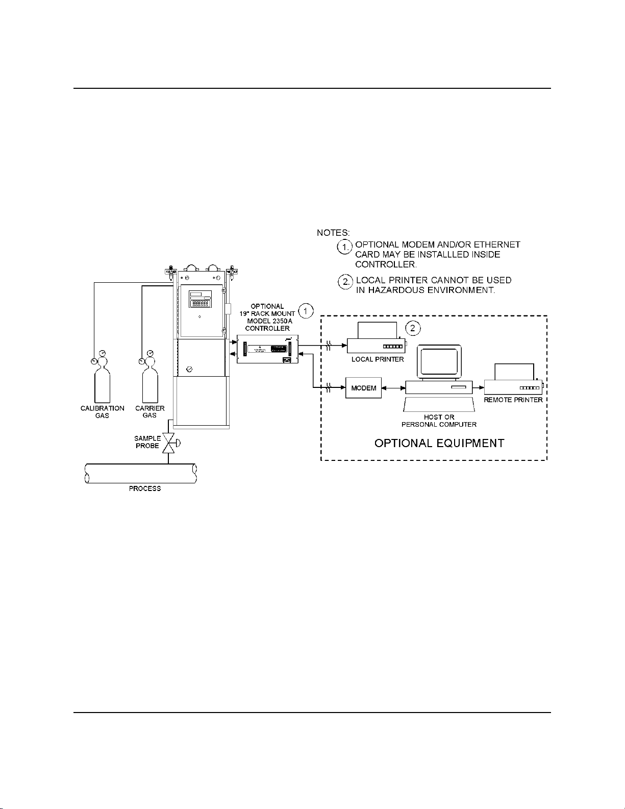
1.3 FUNCTIONAL DESCRIPTION
A functional block diagram of a typical GC System installation is shown in Figure 1-1. A sample
of the gas to be analyzed is taken from the process stream by a sample probe installed in the process
line. The sample passes through a sample line to the sample conditioning system where it is filtered
or otherwise conditioned. After conditioning, the sample flows to the Analyzer for separation and
detection of the components of the gas.
The chromatographic separation of the sample gas into its components is accomplished in the
Analyzer in the following manner. A precise volume of sample gas is injected into one of the unit's
analytical columns. The column contains a stationary phase (packing) that is either an active solid
(adsorption partitioning) or an inert solid support that is coated with a liquid phase (absorption
partitioning). The gas sample is moved through the column by means of a mobile phase (carrier
gas). Selective retardation of the components of the sample takes place in the column that causes
each component to move through the column at a different rate. This action separates the sample
into its constituent components.
A detector located at the outlet of the analytical column senses the elution of components from the
column and produces electrical outputs proportional to the concentration of each component.
Outputs from the Analyzer detectors are amplified in the Analyzer electronics, then transmitted to
the GC Controller for further processing. (See also, Section 1.6, "Theory of Operation.")
Output from the GC Controller is normally displayed on a remotely located personal computer (PC)
or a printer. Connection between the GC Controller and the PC can be accomplished via a direct
serial line or via the Modbus-compatible communication interface.
Multiple chromatograms may be displayed on the PC monitor, and compared or contrasted with
separate color schemes. This allows a stored chromatogram to be compared/contrasted with a
current or another stored chromatogram. This could be of great assistance when changing
parameters or isolating a problem.
Use of a PC for configuration and troubleshooting procedures is essential in most instances. (Basic
operations can also be performed from a keyboard and liquid crystal display that are built into certain
versions of the GC Controller.) The PC may be remotely connected via telephone, radio or satellite
communications. Once installed and configured, the GC System can operate independently for long
periods of time.
DESCRIPTION
1-5
SEP 2005 MODEL 1000
1-6
Figure 1-1. GC System Functional Block Diagram
DESCRIPTION

MODEL 1000 SEP 2005
1.4 MINIMUM PC REQUIREMENTS
To achieve maximum performance when running the MON2000 software, ensure your PC system
contains the following hardware and software equipment.
• PC with a 486/90 MHz or higher processor (Pentium/100MHz or higher recommended)
running:
- Windows® 95 (service pack 1 or better) or later
If running Windows® 95 with the optional Ethernet card, the user must download Socket 2
from www.microsoft.com/windows95/downloads to utilize MON2000’s Ethernet feature.
- Windows® 98 version 1 or later
- Windows® 2000 version 1 or later
- Windows® XP version 1 or later (see note for system requirements)
- Windows® NT version 4 (service pack 3 or later)
• 16 megabytes (MB) of RAM (32 MB or higher recommended)
• 5 MB of free hard disk space
• Super VGA monitor with 800x600 resolution
• Free serial port for remote/local connection to gas chromatograph (for online operations)
• Free parallel port for connection to printer
• Windows®-compatible modem (for remote connection only)
DESCRIPTION
1-7
SEP 2005 MODEL 1000
Microsoft Internet Explorer 5.0 is required to view spreadsheets or reports saved in HTML
format.
• Use the Settings>Control Panel>System>General Page menu path to check the system
version number.
- For Windows® 95, the version number should be 4.00.950A/B or later.
- For Windows® 98 or Windows® 2000, the version number should be 1 or later.
- To use Windows® XP you need, Computer/Processor PC with 300 MHz or higher
processor clock speed recommended; 233 MHz minimum required (single or dual
processor system);* Intel Pentium /Celeron® family, or AMD K6®/Athlon™/
®®
Duron™ family, or compatible processor recommended.
- Memory 128 MB of RAM or higher recommended (64 MB minimum supported; may
limit performance and some features)
- Hard Disk Minimum: 1.5 GB of available hard disk space
- For Windows NT4, the version number should be 4.00.1381 or later.
1-8
DESCRIPTION

MODEL 1000 SEP 2005
1.5 MODES OF OPERATION
1.5.1 User Interfaces
You have at least one, and optionally two, user interfaces from which to operate the gas
chromatograph (GC) system:
PC connected to the GC and running MON2000 - The PC connected to the GC and running the
MON2000 offers the greatest amount of capability and flexibility.
Find complete user instructions for MON2000 in the program’s online HELP screens and in
the program user’s manual, MON2000 Software for Gas Chromatographs User Manual (P/N
3-9000 -522).
or
The GC Controller’s built-in keyboard and LCD - The GC Controller’s optional built-in
keyboard and LCD offer essential startup and operation functions. They are useful in a
hazardous environment or if no PC is available.
See Section 4, this manual, for details on how to use the GC Controller’s built-in keyboard
and LCD for startup and routine operations in a hazardous environment.
DESCRIPTION
1-9

SEP 2005 MODEL 1000
1.5.2 Capabilities
Individual gas chromatograph Controller functions that can be initiated or controlled by the GC
System and its software, MON2000, include (but are not limited to) the following:
valve activations
timing adjustments
stream sequences
heater controls (when applicable)
calibrations
baseline runs
analyses
halt operation
stream/calculation assignments
diagnostics
alarm and event processing
event sequence changes
component table adjustments
calculation adjustments
alarm parameters adjustments
analog scale adjustments
stream/detector assignments
stream/component table assignments
Reports and logs that can be produced, depending upon the GC Application in use, include (but are
not limited to) the following:
configuration report
parameter list
analysis chromatogram
alarm log (unacknowledged and active)
event log
analysis raw data
chromatogram comparison
1-10
DESCRIPTION
MODEL 1000 SEP 2005
1.6 THEORY OF OPERATION
See Section 1.7, the “Glossary” section of this manual, for definitions of some of the
terminology used in the following explanations.
1.6.1 Analyzer Detector
The Analyzer detector subsystem is a thermal conductivity detector that consists of a balanced
bridge network with heat-sensitive thermistors in each leg of the bridge. Each thermistor is enclosed
in a separate chamber of the detector block. One thermistor is designated the reference element and
the other the measurement element. A schematic diagram of the thermal conductivity detector is
shown in Figure 1-2.
DESCRIPTION
Figure 1-2. Schematic Diagram of Analyzer Detector Bridge
1-11

SEP 2005 MODEL 1000
In the quiescent condition (prior to injecting a sample), both legs of the bridge are exposed to pure
carrier gas. In this condition, the bridge is balanced and the bridge output is electrically nulled. (The
bridge can be balanced by the fine and coarse adjustment potentiometers located on the preamplifier
circuit board.)
The analysis begins when a fixed volume of sample is injected into the column by operation of the
sample valve. The sample is moved through the column by the continuous flow of carrier gas. As
successive components elute from the column, the temperature of the measurement element changes.
The temperature change unbalances the bridge and produces an electrical output proportional to the
component concentration. The differential signal developed between the two thermistors is amplified
by the preamplifier.
Figure 1-3 illustrates the change in detector electrical output during elution of a component.
Figure 1-3. Detector output during component elution
1. Detector bridge balanced.
2. First component begins to elute from column and to be sensed by the measurement
thermistor.
3. Peak concentration of first component.
4. Second component begins to elute from column and to be sensed by the measurement
thermistor.
5. Peak concentration of second component.
In addition to amplifying the differential signal developed between the detector's two thermistors,
the preamplifier also supplies drive current to the detector bridge. The preamplifier also supplies
drive current to the detector bridge. The voltage signal is converted to a 4 to 20-milliamp (mA)
current loop for transmission to the GC Controller. The signal is proportional to the concentration
of a component detected in the gas sample. The preamplifier provides four different gain channels
as well as compensation for baseline drift. The signals from the preamplifier are sent to the GC
Controller for computation, recording on a printer, or viewing on a PC monitor or LCD.
1-12
DESCRIPTION

MODEL 1000 SEP 2005
1.6.2. Data Acquisition
Every second, exactly 40 equi-spaced data samples are taken for analysis by the GC Controller (i.e.,
once every 25 milliseconds). Each data sample, after having been precision-amplified, is subjected
to a twelve bit analog to digital (A/D) conversion. The sampling frequency of 40 Hertz (Hz) was
chosen to reduce 60 Hz normal mode noise.
After each point on the chromatograph signal is sampled, the resulting number is stored in a buffer
area in the GC Controller’s memory for processing. During the analysis, only the last 256 data
points are available for processing. Because the data analysis is done as the signal is sampled (in
real-time), only a limited number of past data samples is required to analyze any signal.
As a part of the data acquisition process, groups of incoming data samples are averaged together
before the result is stored to the Controller’s memory for processing. Non-overlapping groups of N
samples are averaged and stored, and thus reduce the effective incoming data rate to 40/N
samples/second. For example, if N = 5, then a total of 40/5 or 6 (averaged) data samples are stored
every second. The value for the variable N is determined by the selection of a Peak Width parameter
(PW). The relationship is:
N = PW seconds,
where PW is given in seconds. All the various details in the analysis process are independent of the
value of N. Allowable values of N are 1 to 63, which corresponds to values of PW from 2 to 63
seconds.
The variable N is known as the integration factor. This term is used because N determines how
many points are averaged or integrated to form a single value. The integration of data upon input,
before storing, serves two purposes. First, the statistical noise on the input signal is reduced by the
square root of N. In the case of N = 4, a noise reduction of two would be realized. Secondly, the
integration factor controls the bandwidth of the chromatograph signal. It is necessary to match the
bandwidth of the input signal to that of the analysis algorithms in the GC Controller. This prevents
small, short duration perturbations from being recognized as true peaks by the program. It is
therefore important to choose a Peak Width corresponding to the narrowest peak in a group under
consideration.
DESCRIPTION
1-13

SEP 2005 MODEL 1000
1.6.3 Peak Detection
For normal area or peak height concentration evaluation, the determination of a peak's start, peak
point, and end is automatic. The manual determination of start and end points is used only for area
calculations in the Forced Integration mode. Automatic determination of peak onset or start is
initiated whenever Integrate Inhibit is turned off. Analysis is started in a region of signal quiescence
and stability, such that the signal level and activity can be considered as baseline values. It is
important that this be the case because the assumption is made by the GC Controller software.
Having initiated a peak search by turning Inhibit off, the GC Controller performs a point by point
examination of the signal slope. This is achieved by using a digital slope detection filter which is
a combination low pass filter and differentiator. The output of this detector is constantly compared
to a system constant entered by the operator called Slope Sensitivity. A default value of 8 is assumed
if no entry is made. Lower values make peak onset detection more sensitive, and higher values make
detection less sensitive. Higher values (20 to 100) would be appropriate for noisy signals, e.g. high
amplifier gain.
Peak termination is determined by the same application of this detector to the signal, but in the
reverse sense. Onset is defined where the detector output exceeds the baseline constant, but
termination is defined subsequently where the detector output is less than the same constant.
Sequences of fused peaks are also automatically handled. This is done by testing each termination
point to see if the region immediately following it satisfies the criteria of a baseline. A baseline
region must have a slope detector value less than the magnitude of the baseline constant for a number
of sequential points. When a baseline region is found, this terminates a sequence of peaks.
A zero reference line for peak height and area determination is established by extending a line from
the point of the onset of the peak sequence to the point of the termination. The values of these two
points are found by averaging the four integrated points just prior to the onset point and just after the
termination points, respectively. The zero reference line will, in general, be non-horizontal, and thus
compensates for any linear drift in the system from the time the peak sequence starts until it ends.
1-14
DESCRIPTION

MODEL 1000 SEP 2005
In a single peak situation, peak area is the area of the component peak between the curve and the
zero reference line. The peak height is the distance from the zero reference line to the maximum
point on the component curve. The value and location of the maximum point is determined from
quadratic interpolation through the three highest points at the peak of the discrete valued curve stored
in the GC Controller.
For fused peak sequences, this interpolation technique is used both for peaks as well as valleys
(minimum points). In the latter case, lines are dropped from the interpolated valley points to the zero
reference line to partition the fused peak areas into individual peaks. The use of quadratic
interpolation improves both area and height calculation accuracy and eliminates the effects of
variations in the integration factor on these calculations.
For calibration, the GC Controller may average several analyses of the calibration stream.
DESCRIPTION
1-15
SEP 2005 MODEL 1000
1.6.4 Basic Analysis Computations
Two basic analysis algorithms are included in the GC Controller. These are:
Area Analysis - Calculates area under component peak
Peak Height Analysis - Measures height of component peak
Concentration Analysis by Using Response Factor
Concentration calculations require a unique response factor for each component in an analysis.
These response factors may be manually entered by an operator or determined automatically by the
system through calibration procedures (with a calibration gas mixture that has known
concentrations).
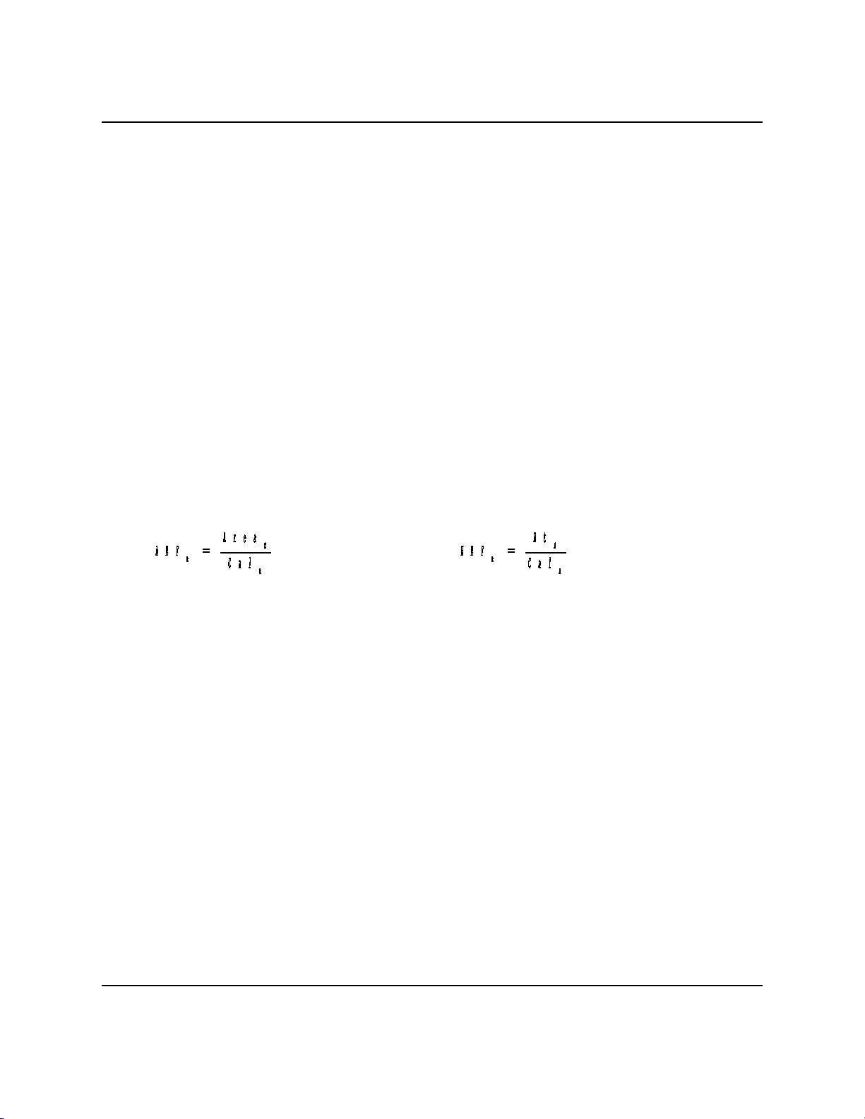
Response factor calculation: (using the external standard)
or
Where:
ARF = Area response factor for component “n” in area per mole percent (%)
n
HRF = Height response factor for component “n”
n
Area = Area associated with component “n” in calibration gas
n
Ht = Height associated with component “n” in mole % in calibration gas
n
Cal = Amount of component “n” in mole % in calibration gas
n
Calculated response factors are stored by the GC Controller for use in the concentration calculations,
and are printed out in the configuration and calibration reports.
1-16
DESCRIPTION
MODEL 1000 SEP 2005
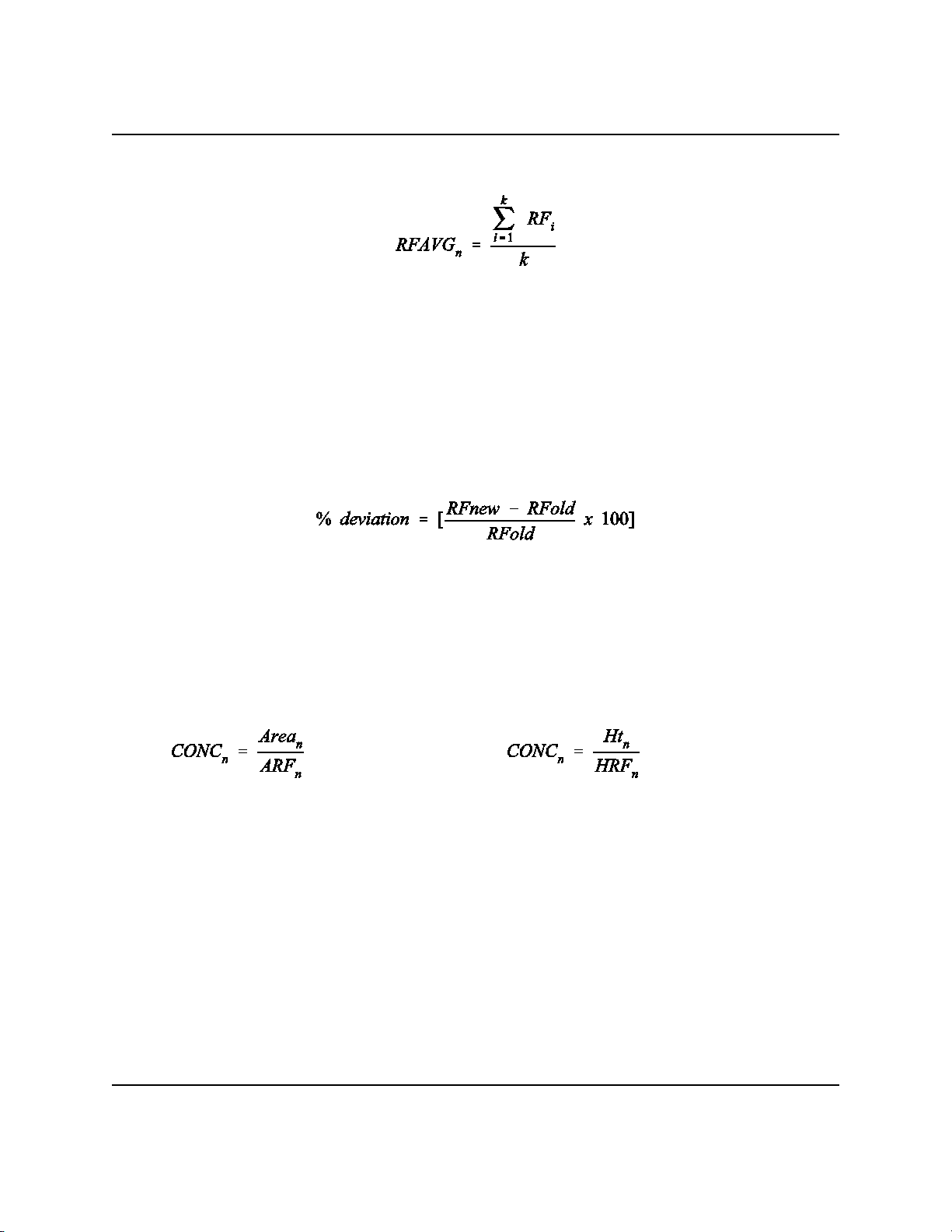
Average response factor is calculated as follows:
Where:
RFAVG = Area or height average response factor for component “n”
Rf = Area or height response factor for component “n” from the calibration
n
i
run
k = Number of calibration runs actually used to calculate the response
factors
The percent deviation of new RF averages from old RF average is calculated in the following
manner:
Where the absolute value of % deviation for alarm has been previously entered by the operator.
Concentration Calculations in Mole % without Normalization
Once response factors have been determined by the GC Controller or entered by the operator,
component concentrations are determined for each analysis by using the following equations:
or
Where:
CONC = Concentration of component “n” in mole %
Area = Area of component “n” in unknown sample
ARF = Response factor of component “n” calculated from area of calibration
n
n
n
sample. Units are area per mole %.
Ht = Peak height of component “n” in unknown sample
n
HRF = Response factor of component “n” calculated from peak height of
n
calibration sample. Units are height per mole %.
DESCRIPTION
1-17
SEP 2005 MODEL 1000
Note that the average concentration of each component will also be calculated when data averaging
is requested.
Component concentrations may be input through analog inputs 1 - 4 or may be fixed. If a fixed
value is used, the calibration for that component is the mole % that will be used for all analyses.
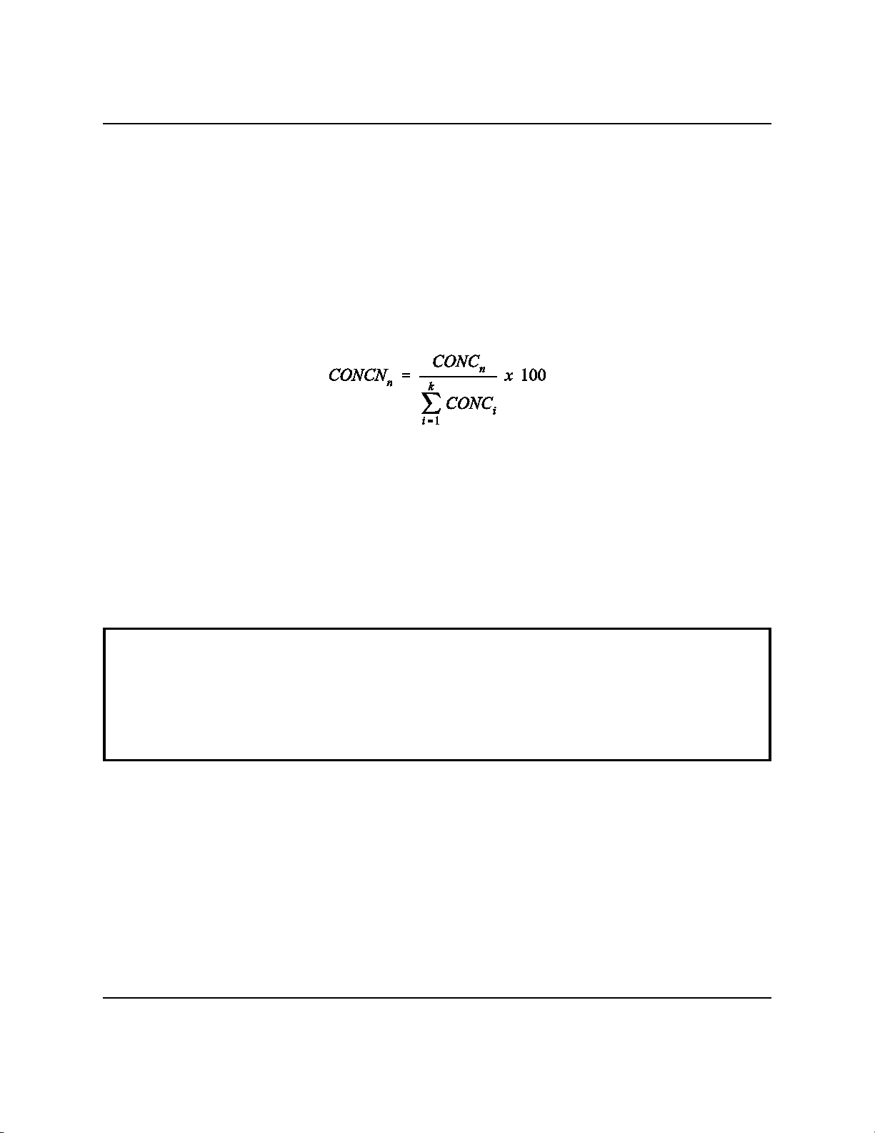
Concentration Calculations with Normalization
Where:
CONCN = Normalized concentration of component “n” in percent of total gas
n
concentration.
CONC = Non-normalized concentration of component “n” in mole %
CONC = Non-normalized concentration (in mole %) from each of the “k”
n
i
components to be grouped into this normalization
k = Number of components to be included in the normalization
For additional information about other calculations that are performed by the GC Controller
and software, see the MON2000 Software for Gas Chromatographs User Manual (P/N 39000-522).
1-18
DESCRIPTION

MODEL 1000 SEP 2005
1.7 GLOSSARY
Auto Zero: Automatic zeroing of the preamplifier. May be entered into the Controller to take place
at any time during the analysis when either the component is not eluting or the baseline is
steady.
Chromatogram: A permanent record of the detector output. A chromatograph is obtained from a
PC interfaced with the detector output through the GC Controller. A typical chromatogram
displays all component peaks, and gain changes. It may be viewed in color as it is processed
on a PC VGA display. Tick marks recorded on the chromatogram by the GC Controller
indicate where timed events take place.
Component: Any one of several different gases that may appear in a sample mixture. For example,
natural gas usually contains the following components: nitrogen, carbon dioxide, methane,
ethane, propane, isobutane, normal butane, isopentane, normal pentane, and hexanes plus.
Condulet: Fitting resembling a pipe or a box with a removable cover for access to electric conduits.
CTS: Clear to send (a serial port pin assignment).
DCD: Data carrier detect; see also, RLSD (a serial port pin assignment).
DSR: Data set ready (a serial port pin assignment).
DTR: Data terminal ready (a serial port pin assignment).
DESCRIPTION
1-19

SEP 2005 MODEL 1000
Response Factor: Correction factor for each component as determined by the calibration. It is
defined by the equation:
or
Where:
ARF
HRF
Area
Ht
Cal
= Area response factor for component “n” in area per mole percent (%)
n
= Height response factor for component “n”
n
= Area associated with component “n” in calibration gas
n
= Height associated with component “n” in mole % in calibration gas
n
= Amount of component “n” in mole % in calibration gas
n
Retention Time: The time (in seconds) that elapses between start of analysis (0 seconds) and the
sensing of the maximum concentration of each component by the Analyzer detector.
RI: Ring indicator (a serial port pin assignment).
RLSD: Received line signal detect (a digital simulation of carrier detect); see also, DCD (a serial
port pin assignment).
RTS: Request to send (a serial port pin assignment).
RxD, RD, or S : Receive data, or signal in (a serial port pin assignment).
TxD, TD, or S : Transmit data, or signal out (a serial port pin assignment).
IN
OUT
1-20
DESCRIPTION

MODEL 1000 SEP 2005
2.0 EQUIPMENT DESCRIPTION
This section provides descriptions of the various subsystems and components that make up the
Model 1000 Gas Chromatograph System. This section is organized as follows:
Sampling System ................................................. See Section 2.1
Sampling Point Location .............................................. 2.1.1
Sample Volume and Flow Rate ......................................... 2.1.2
Sample Conditioning ................................................. 2.1.3
Contamination Precautions ............................................ 2.1.4
Valving..................... ............ ......... ......... ......... 2.1.5
Calibration Gas ..................................................... 2.1.6
Analyzer ........................... .................. ......... See Section 2.2
Physical Description ................................................. 2.2.1
Chromatograph Valves ............................................... 2.2.2
Primary Plate .................................................. 2.2.2.1
Actuating Subassemblies ......................................... 2.2.2.2
Operation .................. ......... ......... ............ ..... 2.2.2.3
Detector Subsystem .................................................. 2.2.3
Analyzer Preamplifier Unit ............................................ 2.2.4
Analyzer Specifications ............................................... 2.2.5
Utility Gas Requirements .............................................. 2.2.6
Controller ........................... .................. ......... See Section 2.3
Controller Hardware Configurations ..................................... 2.3.1
Analog Inputs and Outputs ........................................ 2.3.1.1
Digital Inputs and Outputs ........................................2.3.1.2
Communications .................. ............ ......... ......... 2.3.1.3
Driver Outputs ................................................. 2.3.1.4
General Controller Specifications ...................................2.3.1.5
Electrical/Mechanical Safety and Integrity -
Certifications and Classifications ...................................2.3.1.6
GC Controller Circuit Board List ................................... 2.3.1.7
Optional Keyboard and Display ......................................... 2.3.2
Keypad ........................... ............ ......... ....... 2.3.2.1
Display ....................................................... 2.3.2.2
Alarm Specifications ................................................. 2.3.3
Status Indicators ................................................ 2.3.3.1
EQUIPMENT DESCRIPTION
2-1

SEP 2005 MODEL 1000
2.1 SAMPLING SYSTEM
A well designed, properly adjusted sampling system is essential to optimum performance of any gas
chromatograph. If a good sample is not obtained for analysis, the whole purpose of the system is
compromised.
The purpose of the sample handling system is to transfer a conditioned fluid sample that is
compatible with gas chromatography requirements.
The Sample Conditioning System (SCS) is located between the process stream and the Analyzer, and
is usually mounted on the lower portion of the Analyzer stand. It serves these purposes:
- Extracts final sample from the fast loop,
- Performs final filtration,
- Performs stream switching for a multi-stream Analyzer, and
- Adjusts the final pressure, temperature, and flow control on the selected sample
flowing to the sample valve.
The following points should be considered in selecting and installing a sampling system:
- Sample Paint
- Sample Volume and Flow Rate
- Sample Conditioning
- Contamination Precautions
- Valving
- Calibration Gas
2.1.1 Sampling Point Location
Gas samples must be representative of the process stream and must be taken from a location where
stratification or separation of components does not occur. The sampling point should be as close as
feasible to the Analyzer.
2.1.2 Sample Volume and Flow Rate
An adequate response time for sample analysis requires that sample volumes should generally be as
small as possible, and the flow rate between the sampling point and the Analyzer should be as high
as possible, consistent with accuracy. To minimize time lag and to prevent back diffusion, dryers
and filters in the sampling line should be as small as possible. When long sampling lines cannot be
avoided, flow velocity in the line can be increased by decreasing the downstream pressure.
2-2
EQUIPMENT DESCRIPTION

MODEL 1000 SEP 2005
Typically, pressure is reduced at the sample point with a pressure regulating sample probe. The input
pressure to the Analyzer can be adjusted between 10 and 20 pounds per square inch, gauge (psig).
Reducing the pressure at the sample point avoids the problem of heavy liquid dropout in the sample
line during cold weather. The flow rate in the sample line is set at 50 cubic centimeters (cc) per
minute with the restrictor valve at the Analyzer.
The Model 1000 is capable of accepting liquid phase samples also. In this case, the pressure is
regulated by means of a back pressure regulator located on the SCS mounting plate. If the stream
is at ambient pressure or under slight vacuum, an educator or pump may be used to force sample
through the sample loop. In this situation, sample shut-off technique with equalizing coil is
employed to ensure consistency of the sample volume.
Use this general rule to approximate sample lag time caused by the length of sample line. Sample
line constructed of 1/8-inch tubing contains approximately 1 cc of volume per foot. Therefore, with
a flow rate of 50 cc per minute, the lag time of the sample between the sample point and the
Analyzer is calculated by dividing the length of the line (in feet) by 50. For example, the sample in
a 100 foot sample line will take 2 minutes to travel the length of the line.
2.1.3 Sample Conditioning
Sample systems should contain at least one filter to remove solid particles from the sample stream.
Most applications require fine-element filters upstream of the Analyzer.
2.1.4 Contamination Precautions
Several precautions are recommended to minimize the possibility of contaminating samples. Except
in special applications, filters should be of either the ceramic or the porous metallic type to avoid the
absorption losses characteristic of fiber or paper filters. Pressure regulators and flow controllers
containing cork or felt filters or absorbent diaphragms should not be used. Sampling lines for
noncorrosive streams should be stainless steel tubing and must be clean and free of grease. Lines
must be pressure tight to prevent diffusion of moisture or atmospheric gases into the sample. Pipe
threads should be dressed only with Teflon tape on pipe threads and never with pipe thread
compounds (dope).
EQUIPMENT DESCRIPTION
2-3

SEP 2005 MODEL 1000
2.1.5 Valving
A block valve should be installed immediately downstream of the sample takeoff point to permit
shutdown of the system for maintenance. Block valves should be either gate valves or cocks of the
proper material and packing, and should be rated for the process line pressure. Tight seating of all
connections is essential.
2.1.6 Calibration Gas
A calibration gas used for Process analysis should be blended to Primary Standards. Primary
Standards are blended using weights that are traceable to the National Bureau of Standards (NBS).
If the calibration standard is a gas, the standard should not have any component that could drop out
at the coldest temperature to which the gas will be subjected. A typical blend for a temperature of
zero degrees Fahrenheit (0°F) is listed in the following table. No dropout will occur in this
calibration gas if it is blended at a pressure below 250 psig.
Table 2-1. Contents of Example Calibration Gas
Gas Mole Percent
Nitrogen 2.5
Carbon dioxide 0.5
Methane Balance
Ethane 5.0
Propane 1.0
Isobutane 0.3
N-butane 0.3
Neopentane 0.1
Isopen tane 0.1
N-pe ntane 0.1
N-hexane 0.03
If a liquid calibration standard is being used, the head pressure must be sufficient to prevent
bubble-out of components during hot weather.
2-4
EQUIPMENT DESCRIPTION

MODEL 1000 SEP 2005
2.2 ANALYZER
2.2.1 Physical Description
The Analyzer is physically divided into two major sections (see Figure 2-1). The upper section
contains the following components:
• Pneumatically actuated valves that control the flow of the sample and carrier gases
• Valve control
• Heater-block temperature control
• Detector control
• Detector output signal preamplifier.
• GC Controller with optional keypad/display
The lower section is temperature controlled and contains:
• Detector elements
• Analytical columns
• A temperature-controlled heater block
The GC is mounted in a self-supporting rack that may be placed at or near the sample tap. Under
most environmental conditions, the unit requires no additional shelter.
EQUIPMENT DESCRIPTION
2-5

SEP 2005 MODEL 1000
2-6
Figure 2-1. Analyzer Components
EQUIPMENT DESCRIPTION

MODEL 1000 SEP 2005
2.2.2 Chromatograph Valves
A chromatograph valve is shown in Figure 2-2 in exploded view. Its pistons are pneumatically
actuated in both switching directions by the actuating assemblies located below the primary plate.
EQUIPMENT DESCRIPTION
Figure 2-2. Chromatograph Valve
2-7

SEP 2005 MODEL 1000
2.2.2.1 Primary Plate
The primary plate contains precisely machined internal passages that enter and exit the valve at top
ports, each of which is connected to the top and/or bottom of the plate within the valve. The
primary plate, which is the only metallic element that comes in contact with the sample, is isolated
from the remainder of the valve by specially formulated diaphragms.
GC valve should be torqued to 30 Ft. lbs.
2.2.2.2 Actuating Subassemblies
Below the primary plate, pistons are operated by pneumatic pressure applied to actuating diaphragms
through ports in the base plate.
2.2.2.3 Operation
When pneumatic pressure is applied to the actuating diaphragms, the pistons are actuated, thus
forcing the sealing diaphragm against the primary plate. This closes the passages that are connected
at the bottom of the plate. When pressure is removed, the pistons are free to move, and flow is
resumed through the passages.
2.2.3 Detector Subsystem
The operation of the Analyzer detector subsystem was previously discussed in the "Theory of
Operation" section of this manual.
2.2.4 Analyzer Preamplifier Unit
The electrical output from the detector is amplified by the Analyzer preamplifier unit. The
preamplifier also supplies drive current to the detector bridge. The voltage signal is converted to a
4 to 20-milliamp (mA) current loop for transmission to the GC Controller. The signal is proportional
to the concentration of a component detected in the gas sample. The preamplifier provides four
different gain channels and compensates for baseline drift. The signals from the preamplifier are
then sent to the GC Controller, where they provide the basis for analysis computations and a
chromatographic trace, or chromatogram.
2-8
EQUIPMENT DESCRIPTION

MODEL 1000 SEP 2005
2.2.5 Analyzer Specifications
a. Power Requirements: 120 volts, alternating current (VAC), +10/-15VAC; 50 to 60 Hertz
(Hz); single phase; 10 amperes (A) (maximum during warmup) (additional 10 amps if unit
has a Sample System Oven).
b. Ambient Temperature Range: -18 degrees Celsius (°C) to +55°C (0°F to +130°F)
c. Humidity: 0 to 95 percent relative humidity, noncondensing
d. Vibration: Designed for mounting on process piping or other field structures subject to
normal process vibrations
e. National Electrical Code (NEC) Area Classification: Suitable for NEC Class 1, Division 1,
Group D
f. Frame Size (approximately):
- Height: 78 inches (198 centimeters [cm])
- Width: 24 inches (61 cm) maximum
- Depth: 24 inches (61 cm)
g. Weight: Approximately 125 pounds (56.8 kilograms [kg]), including mounting hardware.
h. Sample Requirements:
1. Fluid Phase - Vapor
2. Pressure - 15 to 30 psig, regulated to ±10 percent
3. Flow Rate - 50 cc/min, typical
i. Analyzer Output Signal: Four different gain channels to provide a 4 to 20 mA signal to the
Controller.
j. Transient Over Voltages Category:
Installation Category (Over Voltage Category II)
k. Cleaning requirements are restricted to the 6-port valve (refer to Section 5.5.5.1 Valve
Cleaning, in the manual).
EQUIPMENT DESCRIPTION
2-9

SEP 2005 MODEL 1000
2.2.6 Utility Gas Requirements
a. Carrier Gas: Application dependent, typically zero grade helium, hydrogen or nitrogen
(99.995% pure, with less than 5 ppm water, and less than 0.5 ppm hydrocarbons); pressure
is variable.
b. Valve Actuation Gas: typically zero grade, 99.995% pure helium at 100 psig. Consumption
is 100cc per analysis cycle. Clean, dry air also may be used for valve actuation. Carrier Gas
and Valve Actuation Gas are normally supplied from a common cylinder, since overall gas
consumption is minimal.
2.3 CONTROLLER
The GC Controller is a microprocessor-based device that provides the GC System with highly
accurate timing, precision calculations, pertinent report generation, and an interface with other
devices. The Controller provides both analog outputs and a direct digital link with output devices
through RS-232C, RS-422, or RS-485 ports. Volatile portions of the program are protected by a
lithium battery backup if power is lost or turned off at the unit.
The GC Controller can be linked directly to a PC by serial connection, by a telecommunication link
that uses Modbus protocol, or ethernet connection. This provides the preferred method for operating
the GC System. Limited control of the GC System is also possible through a built-in keypad and
display, which are optional components of the purged, hazardous environment GC Controller
package. The local alphanumeric keypad and display allow for maintenance and minor adjustments
in a hazardous environment.
SERIOUS PERSONAL INJURY OR DEATH POSSIBLE
Do not operate a PC or printer in a hazardous environment.
Failure to observe all safety precautions could result in serious injury or death.
2-10
EQUIPMENT DESCRIPTION

MODEL 1000 SEP 2005
2.3.1 Controller Hardware Configurations
The GC Controller may be provided for hazardous area mounting, 19-inch rack mounting, or used
in a 12-inch rack retrofit kit. See Figure 2-3. The unit consists of an STD-bus based computer and
related boards, including boards for terminating field wiring. The enclosure for hazardous areas
qualifies as flameproof (purged NEMA 4X, Class C and D). Connections to the enclosure are
through one 2-inch (50mm) hole (reduced to 3/4 inch with bushing) and two 1-inch (25 mm) conduit
fittings located in the bottom. These accept matching conduit or cable entries. Field connections
are made through purged conduit or flameproof glands.
Figure 2-3. GC Controller, 19-Inch Rack Mounted Version
EQUIPMENT DESCRIPTION
2-11

SEP 2005 MODEL 1000
For operating a printer (in a nonhazardous area) at the GC Controller site, a DB-25 parallel port is
available on the GC Controller's Terminal Board (TB) for field wiring.
For connecting a PC to the GC Controller at the GC Controller site (for setup, operation, or
maintenance in a nonhazardous area), a DB-9 serial port connector is available on the Controller's
front panel.
The STD-Bus Card Cage inside the GC Controller is equipped with two cards. Card slots are
preassigned so that cables can be consistently routed. However, the COM4A Board, the Modem
Board and the Ethernet Board may be piggy-backed in any order on the CPU Board. If the Radicom
modem is used, it must be the top board in the card cage assembly.
An optional stream switching assembly (with either AC or DC solenoids) can be controlled by the
GC Controller, allowing for switching up to 12 streams.
2.3.1.1 Analog Inputs and Outputs
The GC Controller can accommodate eight fully differential analog 4 to 20 mA input signals. Four
of the analog inputs are used by the associated Analyzer, and they are filtered with transient
protection. The additional four input ports provide the ability to accept signals from other Analyzers,
so that the analytical report of the chromatograph can include other information on the gas stream,
such as water or sulphur content. Transient protection and shield terminations are available for these
inputs.
There is capability for a maximum of ten analog outputs. Two analog outputs are available as
standard components of the Controller; the other eight analog outputs are optional. All ten analog
outputs are current type: 4-20 mA, not isolated. Also, all ten analog outputs can be calibrated by the
MON2000 software.
2-12
EQUIPMENT DESCRIPTION

MODEL 1000 SEP 2005
2.3.1.2 Digital Inputs and Outputs
The Controller has the capability of sixteen digital inputs used as follows:
5 - to read a Modbus address, as defined by DIP switch positions.
2 - to indicate presence and type of front panel as defined by switch positions
1 - Spare
1 - temperature sensor input to shut off LCD backlight
1 - GC alarm, optically isolated, with transient protection
5 - stream flow alarms, optically isolated, with transient protection
1 - photocell detector, front panel backlight (night on, day off)
The Controller has the capability of 22 digital outputs used as follows:
6 - Analyzer control
8 - driver outputs for DC air solenoids (stream switching, 12 total streams)
5 - alarms, optically isolated, with transient protection
3 - front panel indicators (green, yellow, red)
The digital transient-protected discrete outputs can furnish up to 50 mA. If more current is
required (up to 0.5A), a special transient protection plug-in module should be installed (see
Appendix C, this manual, for transient protection module details).
2.3.1.3 Communications
There are 3 to 8 communication ports externally available (depending on options package selected).
The communications ports can use either RS-232, RS-422, or RS-485 protocol, selected by Data
Interface Chips via the CPU Board. The communications ports on these boards are normally
configured at the factory, as specified by the customer's communications requirements. The Modbus
switch positions are also normally set at the factory as specified by the customer. If any changes
need to be made in the field, refer to the drawings in the rear of this manual.
EQUIPMENT DESCRIPTION
2-13

SEP 2005 MODEL 1000
2.3.1.4 Driver Outputs
The GC Controller has eight stream switch outputs, 120 mA continuous current, which can be used
to control optional AC or DC solenoid switch boards. This increases stream switch capability from
the standard capability of four gas streams and 1 calibration gas (CAL) system to a maximum
capability of twelve streams.
The optional stream switching assembly (AC or DC solenoid systems) has provisions for eight
stream routes, but adding this option has the net effect of adding only seven more stream
routes to the standard stream capacity of five (thus giving a total stream capacity of twelve).
The reason is, when the optional stream switch assembly is installed, one of the Analyzer’s
standard five stream routes becomes dedicated to the optional stream switch assembly.
2.3.1.5 General Controller Specifications
a. Power requirements (without current outputs): 63.25VA typical for basic instrument
b. Voltage options:
1. 115 VAC ±15 percent, 50 to 60 Hz @ 0.33 A
2. 230 VAC ± 15 percent, 50 to 60 Hz @ 0.275 A
c. Temperature
1. Operating range: -18°C to 55°C (0°F to 131°F)
2. Storage range: -40°C to 85°C (-40°F to 185°F)
d. Humidity: 0 to 95 percent relative humidity, noncondensing
2-14
EQUIPMENT DESCRIPTION

MODEL 1000 SEP 2005
2.3.1.6 Electrical/Mechanical Safety and Integrity - Certifications and Classifications:
Both the Analyzer electronics and the GC Controller, when housed inside a purged enclosure, meet
these certifications and classifications for electrical and/or mechanical safety and integrity:
National Electrical Manufacturers Association (NEMA) 7 for National Electrical
Code (NEC) Class I, Division 1, Groups C and D areas. Meets Underwriters
Laboratories Inc. (UL) 1203, "Explosion-Proof and Dust-Proof Electrical Equipment
of use in hazardous (Classified) locations" for NEC Class I, Division 1, Groups C
and D, and Canadian Standards Association (C.S.A.) 22.2 No. O-M1962, Part II and
C.S.A. 22.2 No. 30-M1986 for NEC Class I, Division 1, Groups C and D.
EEx d IIB T6 - Meets CENELEC EN 50 014, and EN 50 018, "Electrical Apparatus
for Potentially Explosive Atmospheres...", Parts 1 and 5, as flameproof for Group II,
Subdivision B, Temperature Class T6.
The GC Controller, when housed inside purged enclosure, meets these certifications and
classifications for electrical and/or mechanical safety and integrity:
NEMA 4X - Meets NEMA 250, "Enclosures for Electrical Equipment (1000 volts
maximum)", for type 4X, Canadian Electrical Code, Part II, Rule 2-400 1 d, and
C.S.A. C22.2 No. 94-1967 as C.S.A. enclosure 4, and International Electrotechnical
Commission (IEC) 144, "Degrees of protection of enclosures of Switchgear...", for
IP 65.
EQUIPMENT DESCRIPTION
2-15

SEP 2005 MODEL 1000
Both the Analyzer, when housed inside a purged enclosure, and the GC Controller, when housed
inside (a) the purged enclosure, (b) the rack mount enclosure, or the retrofit enclosure, meet the
following classification for control against excessive radio frequency (RF) emissions:
Federal Communications Commission (FCC) Part 15, Subparts A and B
2.3.1.7 GC Controller Circuit Board List
The GC Controller circuit boards are inserted or attached to an STD-bus card cage assembly. It has
two boards inserted into the card cage, and two of the boards are attached to the card cage outside
(see Figure 3-7).
There are three optional piggy-back boards which can attach to the CPU Board via the PC 104 bus:
1) Modem
2) COM4A (serial ports 5, 6, 7, and 8)
3) Ethernet board
Figure 2-4. GC Controller CPU Board with Modem and COM4A Piggy-Back Board
2-16
EQUIPMENT DESCRIPTION

MODEL 1000 SEP 2005
The inserted circuit boards of the GC Controller perform these functions (see Table 2-2):
Table 2-2. Functions of Inserted Circuit Boards, GC Controller Card Cage Assembly
Subsystems
CPU microprocessor
board
COM4A Board
(CPU Daughter
board)
Modem (CPU
Daughter board)
Analog I/O board
[requires MON2000
software, version 2.3
or later]
Handle Label
or Part Number Function(s)
MCM/LPM-6117 Microprocessor; control of
parallel printer port; control of
COM1, COM2, COM3, and
COM4 communication ports;
system memory; RS-422 serial
protocol; three timers, digital I/O,
and Disk on Chip. Additional
memory for higher capacity data
archives.
Control of COM5-8 BE-20767
telephone modem
Analog* Control of eight analog inputs (4
for user applications and 4 for
Analyzer-Controller interconnect)
and two, six, or ten analog
outputs
See drawing
number...
DE-20782
BE-18044
Ethernet Card (CPU
Daughter board)
EQUIPMENT DESCRIPTION
PCM-NE 2000 Flexible, high-performance
networking capability; broad
spectrum of software support
(from Windows® 95 to Netware
2000 architecture)
2-17

SEP 2005 MODEL 1000
There are two circuit boards attached to the outside of the card cage:
- the System Interface and Driver Board, and
- the GC Controller's Terminal Board for Field Wiring.
The GC Controller's Terminal Board for Field Wiring provides termination connections for these
items:
- Communication ports (COM1, COM2, COM3, COM4, COM5, COM6, COM7, and
COM 8),
- Analog inputs and outputs,
- Digital inputs and outputs,
- Controller-Analyzer interconnections,
- Parallel printer port, and
- Optional stream switching assemblies.
See drawing DE-20782 for an illustration of the GC Controller's Terminal Board for Field
Wiring.
The GC Controller's Terminal Board for Field Wiring also has sockets for transient protection
modules, and a 250 VAC, 2A fuse (5 x 20 mm) that protects all of the boards from transient surges.
See Appendix C and drawing CE-18115 for a list of transient suppression modules that are
installed for various configurations of the GC Controller and its communication, analog
output, and stream-switching options.
2-18
EQUIPMENT DESCRIPTION

MODEL 1000 SEP 2005
The System Interface and Driver Board provides these functions:
- Drivers for switching the eight optional valve solenoids,
- Location for 8-position DIP switch to set the Modbus address,
- Opto-isolation circuits for the discrete inputs and outputs,
- Switching power supply and temperature shutdown circuit for the LCD display,
- RS-232 to RS-422 conversion for the LCD display, and
- Voltage-to-current conversion for the analog outputs.
- Jumper for selecting driving voltage source for the 4-20 mA circuit.
See drawing CE-18118 for an illustration of the System Interface and Driver board.
Also see Figure 2-5, next page. It illustrates, through a block diagram, the function and placement
of the GC Controller circuit boards.
EQUIPMENT DESCRIPTION
2-19

SEP 2005 MODEL 1000
2-20
Figure 2-5. Block Diagram of GC Controller Circuit Boards
EQUIPMENT DESCRIPTION

MODEL 1000 SEP 2005
2.3.2 Optional Keypad and Display
A keypad and liquid crystal display (LCD), optionally built into the enclosure's front panel, are
available for the purged and rack mount versions of the GC Controller. The built-in keypad and LCD
are especially useful for the purged version. They permit onsite display, control, and data entry at
a GC Controller that is situated in a hazardous environment. Note, however, that the control
capabilities offered through the built-in keypad and LCD are more limited than those available
through a PC connected to the GC Controller.
For details on using the Controller's built-in keypad and LCD, see Section 4, this manual.
2.3.2.1 Keypad
The front panel keypad is an 18-Key data/function entry device arranged so that the ALT key causes
the lower key markings to be displayed/entered. The designations marked on the top of the keys will
be displayed/entered when the ALT key is not pressed.
2.3.2.2 Display
The Controller display, measuring 5.5 x 2 inches, is capable of 8 lines by 41 characters. It is certified
for use with a purged NEMA 4X, Class C and D, enclosure. The display is capable of producing the
complete alphabet and numbers from the keypad. The video display on the Controller may show a
truncated (or curtailed) version of the displays available at the PC. Although the keypad/display
located at the Controller site can do many of the functions that the PC software can do remotely, any
extensive operations are more conveniently performed through MON2000 on the larger screen and
keypad of a PC. A few adjustments will be more conveniently accomplished at the Controller site.
2.3.3 Alarm Specifications
In the GC Controller there is the capacity for 36 alarms. There are also operator defined alarms.
Some of the alarms are active only if the configuration of the Controller requires the function that
is associated with those alarms. Active alarms are shown in the ALARMS menu.
EQUIPMENT DESCRIPTION
2-21

SEP 2005 MODEL 1000
2.3.3.1 Status Indicators
Three colored LED status indicators are located at the side of the display on the front panel. The
indicators are arranged from yellow, green, and red. When illuminated, the LED status indicators
signify the following:
- Yellow LED: When illuminated, the Yellow LED indicates that an out-of-tolerance value
or an alarm condition was entered into the Controller memory for printout with the analysis.
The Controller memory retains the alarm for printout until the operator clears the alarm(s).
This indicator is partially application controlled and may be set at different out-of-tolerance
levels with different applications.
- Green LED: When illuminated, the Green LED indicates that the Controller is operating. If
the green LED is illuminated and the Controller does not accept changes, a password lockout
may have been entered. If a password has been entered, the password must be re-entered
before the Controller program can be changed.
- Red LED: When illuminated, the Red LED indicates an out-of-tolerance value or an alarm
condition in the RUN mode that requires operator action. Alarm contacts are closed under
these conditions. The Red LED is automatically turned off and contacts opened by the
Controller at the start of the next analysis.
2-22
EQUIPMENT DESCRIPTION

MODEL 1000 SEP 2005
3.0 INSTALLATION AND SETUP
This section provides instructions for installing and setting up the Model 1000 Gas Chromatograph
system. This section is organized as follows:
Because the Model 1000 Gas Chromatograph system is available in different configurations,
not all of the instructions in this section may apply. In most cases, however, to install and set
up a Model 1000 Gas Chromatograph system, it is recommended that you follow the
instructions in nearly the same order as presented in this manual. (Also see Table 3-1 for a
summary of installation and setup steps.)
Precautions and Warnings ......................................... See Section 3.1
Hazardous Environments .............................................. 3.1.1
Power Source Wiring ................................................. 3.1.2
Signal Wiring ....................................................... 3.1.3
Electrical and Signal Ground ........................................... 3.1.4
Electrical Conduit ................................................... 3.1.5
Sample Systems Requirements ......................................... 3.1.6
Preparat ion ............ ..................... ..................... See Section 3.2
Introduction ........................................................ 3.2.1
Site Selection ....................................................... 3.2.2
Unpacking the Unit .................................................. 3.2.3
Necessary Tools and Components ....................................... 3.2.4
Optional Tools and Components ........................................ 3.2.5
Installing the Analyzer ............................................ See Section 3.3
Point-to-Point Wiring Guide, Analyzer-Controller . . . . . . . . . . . . . . . . . . . . . . . . . . 3.2.3
Analyzer AC-Power Wiring ........................................... 3.3.1
Sample and Gas Lines ................................................ 3.3.3
Installing the GC Controller ........................................ See Section 3.4
Modbus Slave Address Setup (COM ID) Setup . . . . . . . . . . . . . . . . . . . . . . . . . . . . 3.4.1
Controller-Analyzer Wiring ............................................ 3.4.2
Controller-PC Wiring (Serial Connections) . . . . . . . . . . . . . . . . . . . . . . . . . . . . . . . . 3.4.3
INSTALLATION AND SETUP
3-1

SEP 2005 MODEL 1000
Before Connecting ............................................ 3.4.3.1
PC-to-GC, Front Panel Quick and Easy RS-232 . . . . . . . . . . . . . . . . . . . . . 3.4.3.2
PC-to-GC, Permanent Cable Connection for Short Distance RS-232 . . . . . 3.4.3.3
PC-to-GC, Long Distance with RS-422 or RS-485 . . . . . . . . . . . . . . . . . . . 3.4.3.4
CPU and COM4A Serial Communications Setups . . . . . . . . . . . . . . . . . . . . . . . . . . 3.4.4
CPU RS-232/RS-422/RS-485 Configuration . . . . . . . . . . . . . . . . . . . . . . . 3.4.4.1
CPU RS-232 Configuration ..................................... 3.4.4.2
CPU RS-422 Configuration ..................................... 3.4.4.3
CPU RS-485 Configuration ..................................... 3.4.4.4
CPU COM1/COM2, Keyboard and Printer Output Header . . . . . . . . . . . . 3.4.4.5
CPU COM3/COM4 Output Header ............................... 3.4.4.6
COM4A RS-232/RS-422/RS-485 Configuration . . . . . . . . . . . . . . . . . . . . 3.4.4.7
COM4A RS-232 Configuration ................................. 3.4.4.8
COM4A RS-422 Configuration ................................. 3.4.4.9
COM4A RS-485 Configuration ................................ 3.4.4.10
Parallel Printer Interface ......................................3.4.4. 11
P/C104 Bus Interface ........................................ 3.4.4.12
Silicon Disk Configuration .................................... 3.4.4. 13
Multi-I/O Connector ......................................... 3.4.4.14
Parallel I/O Configuration ..................................... 3.4.4.15
Controller-Printer Wiring .............................................. 3.4.5
Discrete (Digital) I/O Wiring ........................................... 3.4.6
Analog I/O Wiring ................................................... 3.4.7
Controller AC-Power Wiring ........................................... 3.4.8
Analyzer Leak Checks and Purging for First Calibration ................ See Section 3.5
Analyzer Leak Checks ................................................ 3.5.1
Purging Carrier Gas Lines ............................................. 3.5.2
Purging Calibration Gas Lines .......................................... 3.5.3
System Start-up .................................................. See Section 3.6
3-2
INSTALLATION AND SETUP

MODEL 1000 SEP 2005
Table 3-1. Summary of Installation and Setup Steps
Observe Precautions and Warnings
1
Plan Site Location
2
Obtain Supplies and Tools
3
Install Analyzer Wiring
4
Install Analyzer Sample & Gas Lines
5
Install GC Controller Wiring
6
see Section 3.1
see Section 3.2
see Section 3.2
see Section 3.3
see Section 3.3
see Section 3.4
7
8
9
10
Perform Leak Checks
see Section 3.5
Purge Carrier Gas Lines
see Section 3.5
Purge Calibration Lines
see Section 3.5
Start Up GC System
see Section 3.6
INSTALLATION AND SETUP
3-3

SEP 2005 MODEL 1000
3.1 PRECAUTIONS AND WARNINGS
The Analyzer electronics and GC Controller, when housed inside a purged enclosure meet the
certifications and classifications identified in Section 2.3.1.6, this manual. Emerson Process
Management does not, however, accept any responsibility for installations of these, or any
attached equipment, in which the installation or operation thereof has been performed in a
manner that is negligent and/or non-compliant with applicable safety requirements.
EQUIPMENT DAMAGE OR PERSONAL INJURY
The responsible body shall operate the equipment as designed and specified by the
manufacturer.
Failure to do so may cause personal injury or damage to the equipment.
3.1.1 Hazardous Environments
Observe Precautions and Warnings
1
Plan Site Location
2
Obtain Supplies and Tools
3
Install Analyzer Wiring
4
»
3-4
INSTALLATION AND SETUP

MODEL 1000 SEP 2005
Follow these precautions if installing or operating the Model 1000 Analyzer instrumentation
in a hazardous area:
(1) Install and operate only the purged version of the GC Controller in a hazardous area.
(2) Do not operate in a hazardous area any printer or personal computer (PC) that is connected
to the GC Controller. To interface with a GC Controller in a hazardous area, use the
Controller's keyboard and liquid crystal display (LCD) that are built into the purged housing
as options. Or, alternatively, use a PC that is located in a nonhazardous area and remotely
connected to the GC Controller.
(3) Ensure that field connections to the Analyzer and the GC Controller are made through purged
conduit or flameproof glands.
EQUIPMENT DAMAGE OR PERSONAL INJURY
Observe ALL applicable regulations when installing purged GC units.
Failure to observe all regulations when installing purged GC units may result in
noncompliance, equipment damage or personal injury.
The purged GC Controller and Analyzer housings are certified for use in locations where fire and
explosion hazards may exist, specifically, areas that are classified by the National Electronics Code
(NEC) as Class I, Division 1, Groups C and D. However, other regulations apply. For example, all
interconnecting runs of cable through conduit must be sealed at least 18 inches beyond the conduit's
point of entry into certified purged housing. Consult your company's policies and procedures and
other applicable requirements documents to determine appropriate wiring and installation practices.
INSTALLATION AND SETUP
3-5

SEP 2005 MODEL 1000
3.1.2 Power Source Wiring
Observe Precautions and Warnings
1
Plan Site Location
2
Obtain Supplies and Tools
3
Install Analyzer Wiring
4
»
Follow these precautions when installing AC power source wiring to the Model 1000 Analyzer
instrumentation:
(1) All wiring must conform to the National Electric Code, local state or other jurisdiction, and
company standards and practices.
(2) Provide single-phase, three-wire, AC power at 115 or 230 volts AC, 50-60 Hz.
(3) A switch or circuit breaker shall be included in the building installation in a safe area.
(a) The switch or circuit breaker is marked as the power disconnect device.
(b) For Rack mount units, the power disconnect switch shall be in close proximity to the
equipment and easily accessible to the operator.
(4) Provide 20 ampere circuit breaker protection so that the major components of the GC system
the Analyzer, the GC Controller, and any optionally installed sample oven or stream
switching devices are all protected by one circuit breaker.
(5) Use multi-stranded copper conductor wire according to the following recommendations:
(a) For power feed distances up to 250 feet (76 meters), use wire size American Wire
Gauge (AWG) 14 (18 Metric Wire Gauge, stranded).
(b) For power feed distances 250 feet to 500 feet (76 meters to 152 meters), use wire size
AWG 12 (25 Metric Wire Gauge, stranded).
(c) For power feed distances 500 feet to 1000 feet (152 meters to 305 meters), use wire
size AWG 10 (30 Metric Wire Gauge, stranded).
3-6
INSTALLATION AND SETUP

MODEL 1000 SEP 2005
3.1.3 Signal Wiring
Observe Precautions and Warnings
1
Plan Site Location
2
Obtain Supplies and Tools
3
Install Analyzer Wiring
4
Follow these general precautions for field wiring digital and analog input/output (I/O) lines:
(1) Metal conduit must be used for all process signal wiring.
(2) Metal conduit used for process signal wiring must be grounded at conduit support points
(grounding the conduit at multiple points helps prevent induction of magnetic loops between
the conduit and cable shielding).
»
(3) Use suitable lubrication for wire pulls in conduit to prevent wire stress.
(4) All process signal wiring should be a single, continuous length between field devices and the
GC Controller. If, however, length or conduit runs require that multiple wiring pulls be
made, the individual conductors must be interconnected with suitable terminal blocks.
(4) Use separate conduits for AC voltage and DC voltage circuits.
(5) Do not place digital or analog I/O lines in same conduit as A-C power circuits.
(6) Use only shielded cable for digital I/O line connections.
(a) Ground the shield at only one end.
(b) Shield-drain wires must not be more than two AWG sizes smaller than the
conductors for the cable.
INSTALLATION AND SETUP
3-7

SEP 2005 MODEL 1000
(7) When inductive loads (relay coils) are driven by digital output lines, the inductive transients
must be diode clamped directly at the coil.
(8) Any auxiliary equipment wired to the GC Controller must have its signal common isolated
from earth/chassis ground.
Applicable to the digital and analog I/O lines connecting to the GC Controller, including the
Analyzer-Controller Interconnect lines: Any loop of extra cable left for service purposes inside
the GC Controller purged housing must not be placed near the conduit entry for AC power.
If the above precaution is not followed, the data and control signals to and from the GC
Controller can be adversely affected.
3-8
INSTALLATION AND SETUP

MODEL 1000 SEP 2005
3.1.4 Electrical and Signal Ground
Observe Precautions and Warnings
1
Plan Site Location
2
Obtain Supplies and Tools
3
Install Analyzer Wiring
4
Follow these general precautions for grounding electrical and signal lines:
(1) For shielded signal conducting cables, shield-drain wires must not be more than two AWG
sizes smaller than the conductors for the cable. Shielding is grounded at only one end.
(2) Metal conduit used for process signal wiring must be grounded at conduit support points
(intermittent grounding of conduit helps prevent induction of magnetic loops between the
conduit and cable shielding).
»
(3) A clamp type ground lug (color green) is located on the inside bottom front of the GC
Controller's case. Chassis ground conductors (color code green) inside the Controller's
enclosure should be stranded, insulated copper wire. These device chassis ground
conductors should all be connected to the clamp type ground lug.
(4) A clamp type ground lug is located on the outside of the GC Controller's case at the rear of
the lower right (facing the operator panel) casting rib. This ground point should be
connected to a copper ground rod as described next.
(5) A single-point ground (the outside case ground lug) must be connected to a copper-clad, 10-
foot long, 0.75" diameter steel rod, which is buried, full-length, vertically into the soil as
close to the equipment as is practical. (Grounding rod furnished by others.)
(6) Resistance between the copper-clad steel ground rod and the earth ground must not exceed
25 Ohms.
INSTALLATION AND SETUP
3-9

SEP 2005 MODEL 1000
(7) The equipment-grounding conductors used between the GC Controller and the copper-clad
steel ground rod must be sized according to the following specifications:
- length, 15 feet or less - AWG 8, stranded, insulated copper wire
(4.6 meters)
- length, 15 to 30 feet - AWG 6, stranded, insulated copper wire
(4.6 to 9.1 meters)
- length, 30 to 100 feet - AWG 4, stranded, insulated copper wire
(9.1 to 30.5 meters)
(8) All inter-enclosure equipment-grounding conductors must be protected by metal conduit.
(9) External equipment, such as data printers, that are connected to the GC Controller should be
powered via isolation transformers to minimize the ground loops caused by the internally
shared safety and chassis grounds.
3-10
INSTALLATION AND SETUP

MODEL 1000 SEP 2005
3.1.5 Electrical Conduit
Observe Precautions and Warnings
1
Plan Site Location
2
Obtain Supplies and Tools
3
Install Analyzer Wiring
4
»
Follow these general precautions for conduit installation:
(1) Conduit cutoffs must be square. Cutoffs must be made by a cold cutting tool, hacksaw, or
by some other approved means that does not deform the conduit ends or leave sharp edges.
(2) All conduit fitting threads, including factory-cut threads, must be coated with a metal-bearing
conducting grease, such as Crouse-Hinds STL or equivalent, prior to assembly.
(3) Temporarily cap the ends of all conduit run runs immediately after installation to prevent
accumulation of water, dirt, or other contaminants. If necessary, swab out conduits prior to
installing the conductors.
(4) Install drain fittings at the lowest point in the conduit run; install seals at the point of entry
to the GC Controller's purged housing to prevent vapor passage and accumulation of
moisture.
(5) Use liquid-tight conduit fittings, such as Myers Scru-Tite or similar, for conduit which is
®®
exposed to moisture.
When conduit is installed in hazardous areas (e.g., areas classified as NEC Class I, Division 1,
Groups C and D), follow these general precautions for conduit installation:
(6) All conduit runs must have an explosion-proof sealing (potting) fitting located within 18
inches (45.5 centimeters) distance from the conduit entrance to explosion-proof housings.
(7) The conduit installation must be vapor tight, with threaded hub fittings, sealed conduit joints
and gaskets on covers, or other approved vapor-tight conduit fittings.
INSTALLATION AND SETUP
3-11

SEP 2005 MODEL 1000
EQUIPMENT DAMAGE OR PERSONAL INJURY
Consult your company's policies and procedures and other applicable requirements
documents to determine wiring and installation practices that are appropriate for
hazardous areas.
Failure to do so may cause personal injury or damage to equipment.
3-12
INSTALLATION AND SETUP

MODEL 1000 SEP 2005
3.1.6 Sample Systems Requirements
Observe Precautions and Warnings
1
Plan Site Location
2
Obtain Supplies and Tools
3
Install Analyzer Wiring
4
Observe the following guidelines for installing GC sample systems:
Sample Line Length: If possible, avoid long sample lines. In case of a long sample line, flow
velocity can be increased by decreasing downstream pressure and using by-pass flow via a
speed loop.
Sample Line Tubing Material:
- Use stainless steel tubing for noncorrosive streams.
»
- Ensure tubing is clean and free of grease.
Dryers and Filters in Sample Line:
- Use small sizes to minimize time lag and prevent back diffusion.
- Install a minimum of one filter to remove solid particles. Most applications require
fine-element filters upstream of the Analyzer.
- Do use ceramic or porous metallic type filters. Do not use cork or felt filters.
Pressure Regulators and Flow Controllers in Sample Line: Do not use types containing cork or
felt filters, or absorbent diaphragms.
Pipe Threads, Dressing: Do use Teflon tape. Do not use pipe thread compounds (dope).
Valving:
- Install a block valve downstream of sample takeoff point for maintenance and
shutdown.
- Block valve should be gate valve or cock valve type, of proper material and packing,
and rated for process line pressure.
INSTALLATION AND SETUP
3-13

SEP 2005 MODEL 1000
3.2 PREPARATION
3.2.1 Introduction
Your Model 1000 Analyzer was started and checked out before it left the factory. Program
parameters were installed in the system and documented in the “PC Config Report” furnished with
your GC System.
3.2.2 Site Selection
Observe Precautions and Warnings
1
Plan Site Location
2
Obtain Supplies and Tools
3
Install Analyzer Wiring
4
»
Follow these guidelines for site selection:
(1) Provide adequate access space for performing maintenance and adjustments.
(a) Allow a minimum of 3 feet (.9 m) in front for operator access.
(b) Allow a minimum of 15 inches (38 cm) at the rear and left side for case removal.
(c) If possible, mount the Analyzer components in a vertical stack configuration; it
provides the greatest operator convenience.
(2) Install the Analyzer as close as possible to the sample stream.
(3) Install the GC Controller no further than 2000 feet (610 meters) away from the Analyzer.
(4) Ensure that exposure to radio frequency (RF) interference is minimal.
3-14
INSTALLATION AND SETUP

MODEL 1000 SEP 2005
3.2.3 Unpacking the Unit
Observe Precautions and Warnings
1
Plan Site Location
2
Obtain Supplies and Tools
3
Install Analyzer Wiring
4
Observe the following checklist for unpacking the unit and inspecting for damage:
(1) Unpack the equipment:
(a) Model 1000 series Analyzer
(b) GC Controller
»
(2) Ensure that all documentation and software are included:
(a) This manual, the Model 1000 Gas Chromatograph Hardware Reference Manual,
P/N 3-9000-541.
(b) The software manual, MON2000 Software for Gas Chromatographs User Manual,
P/N 3-9000-522.
(c) CD(s) with the MON2000 software program and GC Applications.
Installation and startup of the GC System should proceed only if all required materials are on hand
and free from obvious defects. If any parts or assemblies appear to have been damaged in shipment,
first file a claim with the carrier. Next, complete a full report of the nature and extent of the damage
and forward the report immediately to Daniel Measurement Services (DMS), a division of Emerson
Process Management for further instructions. Include complete model number information.
Disposition instructions will be returned immediately by Daniel Measurement Services. Refer to the
Customer Repair Report in the back of this manual.
INSTALLATION AND SETUP
3-15

SEP 2005 MODEL 1000
3.2.4 Necessary Tools and Components
Observe Precautions and Warnings
1
Plan Site Location
2
Obtain Supplies and Tools
3
Install Analyzer Wiring
4
»
Observe the following checklist of tools and components that you will need for installing the
Analyzer and GC Controller:
(1) Chromatographic grade carrier gas: zero grade helium or nitrogen (99.995% pure, with less
than 5 ppm water, and less than 0.5 ppm hydrocarbons).
(2) High pressure dual-stage regulator for the carrier gas cylinder, high side up to 3000 pounds
per square inch, gauge (psig), low side capable of controlling pressure up to 150 psig.
(3) Calibration standard gas with correct number of components and concentrations (see Section
2.1.6, this manual).
(4) Dual-stage regulator for the calibration gas cylinder, low pressure side capable of controlling
pressure up to 30 psig.
(5) Sample probe (fixture for procuring the stream, or sample gas for chromatographic analysis).
(6) 1/8-inch stainless steel (SS) tubing for connecting calibration standard to analyzer, 1/4-inch
SS tubing for connecting helium carrier to the analyzer, 1/8-inch SS tubing for connecting
stream gas to the analyzer.
(7) Miscellaneous Swagelok tube fittings, tubing benders and tubing cutter.
(8) 14 American Wire Gauge (AWG) (18 Metric Wire Gauge) or larger electrical wiring and
conduit to provide 115 or 230 volts AC, single phase, 50 to 60 Hertz (Hz), from an
appropriate circuit breaker and power disconnect switch. (See previous guidelines in Section
3.1.2.)
3-16
INSTALLATION AND SETUP

MODEL 1000 SEP 2005
(9) Liquid leak detector (SNOOP or equivalent).
®
(10) Digital volt-ohm meter with probe-type leads.
(11) A flow measuring device such as Alltech Digital Flow Check™ Flowmeter.
INSTALLATION AND SETUP
3-17

SEP 2005 MODEL 1000
3.2.5 Optional Tools and Components
Observe Precautions and Warnings
1
Plan Site Location
2
Obtain Supplies and Tools
3
Install Analyzer Wiring
4
»
Observe the following checklist of tools and components you may need for installing and using
the GC System:
(1) For operation in a nonhazardous area only: Printer and printer paper.
(2) For operation in a nonhazardous area only: An IBM-compatible PC and a “straight-
through” serial cable connection between the external DB-9 (female) serial ports of the GC
Controller and a serial port of the PC. (For details, see Section 3.4.3.)
SERIOUS PERSONAL INJURY OR DEATH POSSIBLE
Do not operate a PC or printer in a hazardous environment.
Failure to observe all safety precautions could result in serious injury or death.
If you are working in a hazardous area and need to perform routine operations, use the optional
keyboard and LCD that are built into the purged GC Controller (see Section 4 this manual). To
make more significant program changes, however, use a remotely connected PC and the software
program MON2000. (See the MON2000 Software for Gas Chromatographs User Manual, P/N
3-9000-522, for instructions on operating the PC software, MON2000.)
(a) PC Specifications: Refer to Section 1.4.1, Minimum PC Requirements.
3-18
INSTALLATION AND SETUP

MODEL 1000 SEP 2005
(b) Serial Cable Specifications:
- Straight-through serial cable with the following terminations:
- DB-9, male connects to GC Controller external serial port
- DB-9 or DB-25, female connects to PC serial port
(3) Interconnect Cable, P/N 6-4618-122, if not already installed between the Analyzer and GC
Controller. This is a shielded, computer and communications grade, 15-conductor cable for
making the thirteen interconnections between the Analyzer and the GC Controller. This
cable, if not enclosed in conduit between the Analyzer and the GC Controller, is suitable only
for use in non-hazardous environments. The cable must be run inside conduit for hazardous
environments. (For cable termination details, see Section 3.3.1, this manual.)
(4) Direct Serial Connect Cable, P/N 3-2350-068, to connect the PC or an external modem
directly to the one of the GC Controller’s serial ports on the GC Controller’s Terminal Board
for Field Wiring (TB). This cable comes in a customer-specified length. It is terminated
with a DB-9 female plug at one end, for connection to a PC or external modem's serial port,
and six exposed leads at the other end for connection to the one of the GC Controller's serial
ports on the TB. (See Section 3.4.3.3 for directions on how to install this cable.)
(5) Items necessary for connecting the GC Controller to an external modem, a multi-drop serial
network, or other type of remote data transfer system (an example item might be an RS232/RS-485 conversion box for long distance serial transmission).
INSTALLATION AND SETUP
3-19

SEP 2005 MODEL 1000
3.3 INSTALLING THE ANALYZER
3.3.1 Point-to-point Wiring Guide, Analyzer-controller
Observe Precautions and Warnings
1
Plan Site Location
2
Obtain Supplies and Tools
3
Install Analyzer Wiring
4
»
This section applies only to GC systems which have not been shipped "prewired." In most
cases, the purged system will already have had the Analyzer-Controller connections made. If
your system has already been wired, skip this section, and proceed to the next section.
To make wiring connections between the Analyzer and the GC Controller, follow these steps:
(1) Disconnect all electrical power to both the Analyzer and the GC Controller.
(2) Feed the Interconnect Cable through the inlet on the condulet box on top of the upper
enclosure, and make connections to the interconnect terminal board (TB-4) which lies behind
Valve Driver Board (see Figure 3-2).
(a) The Interconnect Cable is computer and control applications grade, 15-conductor,
shielded cable. Individual conductors are stranded tinned copper, #22 AWG-(7x30).
(Also see description in Section 3.2.5, this manual.)
(b) Maximum length of Interconnect Cable (or, the maximum distance between the
Analyzer and the GC Controller) should not exceed 2000 feet (610 meters).
3-20
INSTALLATION AND SETUP

MODEL 1000 SEP 2005
Figure 3-1. Behind the Valve Driver Board is the Interconnect Board Containing TB-4
(3) Loosen and remove the four (4) thumbscrews that hold the Valve Driver Board.
(4) Carefully edge the Valve Driver Board off the holding screws. Do not disconnect the Valve
Driver Board from the cable; merely let the board rest face down, secured by the cable (see
Figure 3-2).
(5) With the Analyzer TB-4 now exposed, connect thirteen of the Interconnect Cable’s fifteen
leads to terminals 11 through 23. See Table 3-2 and Figure 3-3 for purposes and destinations
of leads. Also see “CAUTION”, step (6)(a).
INSTALLATION AND SETUP
3-21

SEP 2005 MODEL 1000
Figure 3-2. Valve Driver Board Resting Face Down from its Cable Allows Access to
TB-4
3-22
INSTALLATION AND SETUP

MODEL 1000 SEP 2005
Table 3-2. Point-to-Point Wiring Guide, Analyzer and GC Controller
Board Acronyms:
- Interconnect Terminal Board of Analyzer (TB-4)
- Terminal Board for Field Wiring at Controller (TB)
Analyzer
(TB-4)
Terminal 11 Function code 1 J19, Terminal 1
Terminal 12 Function code 2 J19, Terminal 2
Terminal 13 Function code 4 J19, Terminal 3
Terminal 14 Function code 8 J19, Terminal 4
Terminal 15 Function code strobe J20, Terminal 1
Terminal 16 Common - function codes J19, Terminal 5
Terminal 17 Auto Zero (AZ) J20, Terminal 2
Terminal 18 Preamp gain channel 1 J18, Terminal 1
Terminal 19 Preamp gain channel 2 J18, Terminal 4
Terminal 20 Preamp gain channel 3 J18, Terminal 7
Terminal 21 Preamp gain channel 4 J18, Terminal 10
Terminal 22 Common - preamp gain J18, Terminal 11
color color
Controller
(TB)
Terminal 23 Alarm function (AF) J20, Terminal 3
Connect the interconnect cable SHIELD to one terminal; specifically, terminal 12 of J18, on
the GC Controller TB.
INSTALLATION AND SETUP
3-23

SEP 2005 MODEL 1000
(a)
EQUIPMENT DAMAGE OR PERSONAL INJURY
Do not apply AC electrical power to the Analyzer or the GC Controller until all electrical
power, interconnection, and external signal connections have been verified, and proper
grounds have been made. Refer to Section 3.1.3 for general precautions concerning
signal wiring.
Failure to properly connect the GC unit may result in serious equipment damage or personal
injury.
(6) Access the GC Controller's Terminal Board for Field Wiring (TB), and connect the other
leads of the Interconnect Cable to the GC Controller's TB (see instructions in Section 3.4.2).
Ensure that the connections correspond to those listed in Table 3-2 and Figure 3-3.
(a) At this time, you may also want to complete the remainder of all electrical
connections at the GC Controller. If so, see all of Section 3.4, this manual.
3-24
INSTALLATION AND SETUP

MODEL 1000 SEP 2005
Figure 3-3. Analyzer and GC Controller Interconnect Leads
INSTALLATION AND SETUP
3-25

SEP 2005 MODEL 1000
(7) After confirming that all Interconnect Cable terminations are correct between the Analyzer
and the GC Controller, lift the Valve Driver Board from its resting position and place it over
the four holding screws.
(a) Reinstall the four thumb screws to secure the Valve Driver Board in place.
(8) If necessary, complete wiring connections between the Analyzer's Valve Driver Board and
any optional stream switch boards.
(9) If necessary, complete wiring for connecting AC power to the Analyzer, with proper
connections to hot, neutral, and ground; but do not turn on AC power to the Analyzer yet
(see CAUTION below; see details for AC power connection to Analyzer in Section 3.3.2,
this manual).
EQUIPMENT DAMAGE OR PERSONAL INJURY
Do not apply AC electrical power to the Analyzer or the GC Controller until all electrical
power, interconnection, and external signal connections have been verified, and proper
grounds have been made.
Failure to properly connect the GC unit may result in serious equipment damage or personal
injury.
(10) Leave the Analyzer's upper enclosure open if you need to connect sample and gas lines.
(You will need to manually operate the sample valve switches on the Valve Driver Board.)
(11) If necessary, proceed to Section 3.3.3 for instructions on connecting sample and gas lines to
the Analyzer.
3-26
INSTALLATION AND SETUP

MODEL 1000 SEP 2005
3.3.2 Analyzer Ac-power Wiring
Observe Precautions and Warnings
1
Plan Site Location
2
Obtain Supplies and Tools
3
Install Analyzer Wiring
4
To connect 115 volts AC-Power to the Analyzer, follow these steps:
(1) Locate the three leads for connecting 115 volts AC-power to the Analyzer.
(a) Leads are "pig-tailed" from the Analyzer power supply through conduit to a customer
power NPT connection at the top of the Analyzer stack.
(b) Leads are colored as follows:
- HOT black
- NEUTRAL white
- GROUND green
»
(2) Connect Analyzer AC-power leads to properly controlled 115 volts AC-power source (i.e.,
with circuit breaker and power disconnect switch).
SERIOUS PERSONAL INJURY OR DEATH POSSIBLE
Do not connect AC power leads without first ensuring that AC power source is switched
OFF.
Failure to observe all safety precautions could result in serious injury or death.
(a) Make power line splices and conduit seals that comply with applicable wiring
requirements (for hazardous environments).
INSTALLATION AND SETUP
3-27

SEP 2005 MODEL 1000
EQUIPMENT DAMAGE OR PERSONAL INJURY
Do not apply AC electrical power to the Analyzer or the GC Controller until all electrical
power, interconnection, and external signal connections have been verified, and proper
grounds have been made.
Failure to properly connect the GC unit may result in serious equipment damage or personal
injury.
(3) If necessary, connect the Analyzer's chassis ground to an external copper ground rod (at
remote locations). See Section 3.1.4, this manual, regarding electrical and signal ground.
3-28
INSTALLATION AND SETUP

MODEL 1000 SEP 2005
3.3.3 Sample and Gas Lines
Install Analyzer Wiring
4
Install Analyzer Sample & Gas Lines
5
Install GC Controller Wiring
6
Perform Leak Checks
7
To install GC sample and gas lines, follow these steps:
Use stainless steel tubing. Keep tubing clean and dry internally to avoid contamination.
Before connecting the sample and gas lines, flow clean air or gas through them. Blow out
internal moisture, dust, or other contaminants.
»
(1) Remove the plug from the Analyzer Sample Vent (SV) line (1/16-inch tubing marked "SV"(
located at the left side of the Analyzer).
At this stage in the installation, the Analyzer Measure Vent (MV) line (marked "MV") is left
plugged until Analyzer leak checks are completed. For regular Analyzer operation, however,
the MV line must be unplugged, or open.
HINT: Do not discard the vent line plugs. They are useful at any time when leak-
checking the Analyzer and its sample or gas line connections.
(a) If desired, connect "SV" vent line to an external (ambient pressure) vent. If the vent
line is terminated in an area exposed to wind, protect the exposed vent with a metal
shield.
(b) Use 1/4-inch or 3/8-inch tubing for vent lines longer than 10 feet.
INSTALLATION AND SETUP
3-29

SEP 2005 MODEL 1000
(2) Connect carrier gas to Analyzer. (DO NOT TURN ON GAS AT THIS TIME.)
See Appendix B, this manual, for a description of a dual-cylinder carrier gas manifold (P/N
3-5000-050) with these features:
- Carrier gas is fed from two bottles.
- When one bottle is nearly empty (100 psig), the other bottle becomes the primary
supply.
- Each bottle can be disconnected for refilling without interrupting GC operation.
(a) Use 1/4-inch stainless steel tubing to conduct carrier gas.
(b) Use dual-stage regulator: high side capacity 3000 psig; low side capacity 150 psig.
(3) Connect calibration standard gas to Analyzer. (DO NOT TURN ON GAS AT THIS TIME.)
(a) Use 1/8-inch stainless steel tubing to conduct calibration standard gas.
(b) Use dual-stage regulator: low side capacity up to 30 psig.
(c) Calibration gas inlet is identified in the applicable Sample Conditioning System
("S.C.S") drawing in the Analyzer drawings addendum to this manual. (See
drawings CE-16120, CE-16220, CE-16320, CE-16420, or CE-16520.)
When installing the calibration standard gas line, take care to follow the proper "S.C.S."
drawing in order to make the correct tubing connection to the auto-cal solenoid. Drawings are
included in this manual which address stream and column gas connections. Choose the
drawing that applies to your installation.
3-30
INSTALLATION AND SETUP

MODEL 1000 SEP 2005
(4) Connect sample gas stream(s) to Analyzer. (DO NOT TURN ON GAS AT THIS TIME.)
(a) Use 1/8-inch or 1/4-inch stainless steel tubing to conduct calibration standard gas.
(b) Ensure that pressure of sample line is regulated to maintain 15-30 psig ±10%.
(c) Sample gas stream inlet(s) are identified in the applicable Sample Conditioning
System ("S.C.S") drawing in the Analyzer drawings addendum to this manual. (See
drawings CE-16120, CE-16220, CE-16320, CE-16420, or CE-16520.)
(5) After all lines have been installed, proceed with Controller wiring connections (see next
section).
(a) Leak check procedures for the GC sample and gas lines are given in Section 3.5.1,
this manual. They require AC power to be turned on at the Analyzer.
INSTALLATION AND SETUP
3-31

SEP 2005 MODEL 1000
3.4 INSTALLING THE GC CONTROLLER
3.4.1 Modbus Slave Address (COM ID) Setup
Install Analyzer Wiring
4
Install Analyzer Sample & Gas Lines
5
Install GC Controller Wiring
6
Perform Leak Checks
7
»
The GC Controller's COM ID is determined by dual inline package (DIP) switch settings. In
most cases, the COM ID setup made at the factory will not require changes. (Unless
otherwise specified by the customer, the DIP switch settings made at the factory give the
Controller a COM ID of 1 (one)).
This section applies only to GC systems which have not been shipped "prewired" or may not
have had the COM ID set according to customer specifications.
Follow the steps in this section only if you wish to do the following:
(1) Change the GC Controller's COM ID, or
(2) Visually inspect and verify the COM ID as determined by the DIP switch settings.
3-32
INSTALLATION AND SETUP

MODEL 1000 SEP 2005
To inspect or change the GC Controller's COM ID setup, follow these steps:
(1) At the GC Controller site, locate the DIP switch as described in the following steps.
SERIOUS PERSONAL INJURY OR DEATH POSSIBLE
Before removing the unit cover from the GC Controller, make certain the power supply
switch is OFF and the AC power cord is disconnected. Observe all safety precautions
when you are working in a hazardous environment.
Failure to observe all safety precautions could result in serious injury or death.
(2) For integrally-mounted Controllers, use a flat head screw driver to remove the access panel
on the right side of the card cage assembly (see Figure 3-4).
Figure 3-4. Right Side View of Rack Mount and Panel Mount Controllers
INSTALLATION AND SETUP
3-33

SEP 2005 MODEL 1000
(3) Inspect or change the DIP switch settings as necessary.
(a) See Table 3-3 as a guide.
(b) Make sure you record in the GC Controller's maintenance records any changes you
make to the switch settings.
Figure 3-5. COM ID DIP Switch
Explanation of DIP Switch Setting
O Switches "1" through "5" form a 5-bit binary number for setting the Modbus slave address
(also known as COM ID or Device ID.)
O Switch number "1" is the least significant bit, and switch number "5" is the most significant
bit.
O Switch to ON = 1
Switch to OFF = 0
O Switch "6" is a spare for future use. Switches “7" and "8" are set as needed for the presence
of an optional LOI (Local Operator Interface) connected via COM8 When the COM4A
Board is installed. If the COM4A Board is not installed, the LOI is connected via COM4.
3-34
INSTALLATION AND SETUP

MODEL 1000 SEP 2005
Table 3-3. Modbus Slave Address (COM ID) DIP Switch Settings
Dip Switch Settings Switch Positions
COM ID 1 2 3 4 5
1 ON OFF OFF OFF OFF
2 OFF ON OFF OFF OFF
3 ON ON OFF OFF OFF
4 OFF OFF ON OFF OFF
5 ON OFF ON OFF OFF
6 OFF ON ON OFF OFF
7 ON ON ON OFF OFF
8 OFF OFF OFF ON OFF
RAM CLEAR
Dip Switch Setting Switch Positions
8
Clears RAM when unit powered down ON
Keeps RAM when unit powered down OFF
(4) When finished with the inspection or changes, reassemble the Controllers using the
following steps.
(a) For integrally-mounted Controllers, reattach the right side Access Panel and secure
with the four flat head screws.
INSTALLATION AND SETUP
3-35

SEP 2005 MODEL 1000
3.4.2 Controller-Analyzer Wiring
Install Analyzer Wiring
4
Install Analyzer Sample & Gas Lines
5
Install GC Controller Wiring
6
Perform Leak Checks
7
»
This section applies only to GC systems which have not been shipped "prewired." In most
cases, the purged system will already have had the Controller-Analyzer connections made. If
your system has already been wired, skip this section, and proceed to the next section.
Applicable to the digital and analog I/O lines connecting to the GC Controller, including the
Analyzer-Controller Interconnect lines: Any loop of extra cable left for service purposes inside
the GC Controller purged housing must not be placed near the conduit entry for AC power.
If the above precaution is not followed, the data and control signals to and from the GC
Controller can be adversely affected.
To make wiring connections between the GC Controller and Analyzer, follow these steps:
(1) Disconnect all electrical power to both the Analyzer and the GC Controller.
(2) Ensure that Interconnect Cable wiring connections to the Analyzer have been made as
explained earlier in Section 3.3.1, this manual.
(3) At the GC Controller site, remove the Controller enclosure's front panel.
3-36
INSTALLATION AND SETUP

MODEL 1000 SEP 2005
(a) For the explosion-proof Controller, the front panel is secured by 16 screws. Remove
those screws first.
(b) Then carefully lower the front panel on its bottom hinges. The front panel is heavy,
so make sure it does not drop and cause damage.
(c) For the rack mount Controller, the rear of the enclosure is open; it allows access for
most field wiring procedures without removing the enclosure.
(4) Locate the GC Controller's Terminal Board for Field Wiring (TB). The TB is attached to the
GC Controller's card cage assembly, facing the enclosure's front panel. (In the rack mount
Controller, the TB faces outward toward the rear of the enclosure.)
(5) Route the Analyzer-Controller Interconnect Cable appropriately, especially in the case of the
purged Controller enclosure.
Figure 3-6. Separate Conduit Entries for Cable In/Out of GC Controller
(6) Make Interconnect Cable wiring connections to the GC Controller TB as listed earlier (see
Section 3.3.1, Table 3-2).
INSTALLATION AND SETUP
3-37

SEP 2005 MODEL 1000
3.4.3 Controller-PC Wiring (Serial Connections)
Install Analyzer Wiring
4
Install Analyzer Sample & Gas Lines
5
Install GC Controller Wiring
6
Perform Leak Checks
7
»
A preferred method for operating a Model 1000 GC System is from a connected personal computer
(PC). The PC must be...
(a) running MON2000 software, and
(b) connected to the GC System by a serial link.
This section of the manual addresses the various possibilities for wiring a serial connection between
a PC and the GC System.
3.4.3.1 Before Connecting
Before connecting a PC to the GC Controller, determine the following:
(1) What serial ports are available at the PC? When you select one, consider these points:
(a) FACT: Standard PC serial ports are type RS-232.
(b) Usually there are two external serial port jacks on a PC, located on the rear panel.
Most often, they are either DB-9 or DB-25 male (see below).
(c) PC serial ports can be designated as "COM1" through "COM8," and they can be used
by other peripheral equipment attached to the PC, such as printers, mice, or modems,
etc.
3-38
INSTALLATION AND SETUP

MODEL 1000 SEP 2005
You will need to connect the GC Controller to one of the PC's available, or unused serial ports.
To determine which PC serial ports are already being used by other equipment and
which port can be used for connecting to the GC Controller, note existing serial
connections, refer to your PC user's manual, and use diagnostic software (such as
Norton Utilities™).
(2) What serial ports are available at the GC Controller? When you select one, consider these
points:
(a) The GC Controller's COM1 serial channel is usually reserved for connecting a PC,
especially for service or troubleshooting purposes, since the GC Controller's
easy-access front panel serial port is connected to serial channel COM1 (see Figure
3-7).
Figure 3-7. The Front Panel Serial Port is Connected to GC Controller's Serial Channel
COM1
INSTALLATION AND SETUP
3-39

SEP 2005 MODEL 1000
(b) COM8 is used for the display/keypad when unit has COM5-8 option (COM4A
Board). However, when the unit has a display/keypad but does not have the COM8
option, COM4 must be RS-232, and is used for the display/keypad. Therefore, there
is no COM4 output on the field terminal board.
(c) The optional Modem piggy-backs on to the CPU 104 BUS (See Internal Modem for
the Gas Chromatograph, drawing BE-20767).
(d) Any one of the Controller's eight serial channels could also be reserved for
connecting to a Data Collection Systems (DCS) or multi-drop serial data highway
system (and thus, would be unavailable for a serial PC connection).
(3) Is the connection to be made in a...
- Nonhazardous environment?
- Short distance between the PC and Controller?
- With temporary or permanent cable connection?
(a) See Section 3.4.3.2, "PC-to-GC, Front Panel Quick and Easy RS-232."
(4) Is the connection to be made in a...
- Hazardous or nonhazardous environment?
- Short distance between the PC and Controller?
- Permanent cable connection?
(a) See Section 3.4.3.3, "PC-to-GC, Permanent Cable Connection for Short Distance RS-
232."
(5) Is the connection to be made with a...
- Long distance between the PC and Controller?
- Permanent cable connection?
(a) See Section 3.4.3.4, "PC-to-GC, Long Distance with RS-422 or RS-485."
3-40
INSTALLATION AND SETUP

MODEL 1000 SEP 2005
3.4.3.2 PC-to-GC, Front Panel Quick and Easy RS-232
The easiest way to connect a PC to the GC Controller is with an 'off-the-shelf', straight-through serial
cable connected to the GC Controller's front panel DB-9 serial port jack.
To connect a PC to the GC Controller's front panel DB-9 serial port jack, proceed as follows:
SERIOUS PERSONAL INJURY OR DEATH POSSIBLE
Do not operate a PC in a hazardous environment. Do not make or break front panel
wiring connections in a hazardous environment. In a hazardous environment, ensure
that field connections to the Analyzer or GC Controller (including serial port) are made
through explosion-proof conduit or flameproof glands.
Failure to observe all safety precautions could result in serious injury or death.
(1) Obtain a "straight-through" serial cable:
(a) 50 feet long or less,
(b) DB-9 or DB-25 female plug at one end (for PC connection), and
(c) DB-9 male plug at the other end (for GC connection).
(d) You can buy this type of cable, with plug-ends already installed, from most computer
supply retailers, so there should be no need to custom-wire a serial cable for this type
of connection. (If, however, it is necessary to custom-wire a cable because of
circumstances, see guidelines provided in Appendix A, this manual.)
(2) Connect the serial cable's plugs to the appropriate serial port jacks at the PC and GC (front
panel). Then use the software MON2000 to "Connect" and operate the GC as needed.
INSTALLATION AND SETUP
3-41

SEP 2005 MODEL 1000
3.4.3.3 PC-to-GC, Permanent Cable Connection for Short Distance RS-232
Another way to connect a PC to the GC Controller is with straight-through serial cable connected
to one of the GC Controller's internal serial ports located on the Controller's Terminal Board for
Field Wiring (TB).
If the length of cable can be 50 feet or less, connect the serial cable to one of the GC Controller's
serial ports configured for RS-232. (Recall that output from a standard PC serial port follows RS232 serial definition.) Cable that is longer than 50 feet, when used for RS-232 serial transmission,
can result in spurious loss or corruption of data.
To connect a PC to one of the GC Controller's internal serial port jacks, proceed as follows:
(1) Access the GC Controller's Terminal Board for Field Wiring (TB).
(a) If necessary, see instructions provided in Section 3.4.1, step (1).
(2) Choose an available serial port on the TB that is configured for RS-232 serial protocol.
Unless specified otherwise by customer order, all serial channels on all versions of the GC
Controller are configured by default from the factory for RS-232. For the Rack mount,
retrofit, and purged versions of the GC Controller, and serial channel, COM4 is used for the
keypad and display without the COM4A Board. With the COM4A Board installed, COM8 is
used for the keypad and display. For further details, see Section 3.4.4, this manual, and
drawing DE-20782, GC Controller drawings addendum.
(a) The easiest option is to use a "straight-through" serial cable, like the one described
for the GC Controller front-panel connection (see Section 3.4.3.2), and connect it to
either one of the DB-9 female jacks on the TB.
3-42
INSTALLATION AND SETUP

MODEL 1000 SEP 2005
(b) Another option is to use a Direct Serial Connect Cable (P/N 3-2350-068), or fabricate
one like it.
- Connect the DB-9 female plug end to the DB-9 male serial port on the PC.
- Connect the cable's exposed leads to the GC serial port on the TB.
- When the DB-9 female plug of the cable is connected to a standard PC, its six
leads will be configured for RS-232 as shown in Table 3-4.
Table 3-4. Direct serial connect cable, P/N 3-2350-068
Function at PC’s
serial port
Pin number of
the female DB-9
plug
Exposed
lead
color
Connect exposed leads
to one of GC
Controller RS-232
serial COM ports on
Terminal Board (TB)
for field wiring:
(J5, J6, J10, or J11)
pin number...
DCD (RLSD) 1 red 1 - DCD (RLSD)
S (RxD) 2 white 2 - S (TxD)
IN OUT
S (TxD) 3 black 3 - S (TxD)
OUT IN
GND 5 green 5 - GND
RTS 7 blue 8 - CTS
CTS 8 brown 7 - RTS
(c) Still another option is to fabricate a serial cable and its plug-ends by following
guidelines provided in Appendix A, this manual.
INSTALLATION AND SETUP
3-43

SEP 2005 MODEL 1000
3.4.3.4 PC-to-GC, Long Distance with RS-422 or RS-485
RS-422 and RS-485 serial protocols are recommended for longer distance serial connections between
the PC and GC System (i.e., distances greater than the 50 feet).
To connect a PC to one of the GC Controller's internal serial port jacks that accept RS-422 or
RS-485 serial protocol, proceed as follows:
(1) Obtain the following equipment:
(a) An asynchronous line driver / interface device with RS-232 input, and RS-422 or RS-
485 output. (See Appendix A, this manual, for example brand and model.)
(b) Shielded, computer-grade, twisted pair cable (to connect the asynchronous line driver
device to the GC).
(c) A straight-through serial cable (to connect the PC to the line driver).
(2) Connect the straight-through serial cable from the PC's serial port to the RS-232 serial port
of the line driver device. Then connect the twisted pair cable to the RS-422/RS-485 serial
port of the line driver.
(3) Configure the line driver for data communications equipment (DCE) operation. (See
Appendix A, this manual, for an example configuration of a "Black Box" brand, model
LD485A-MP "RS-232/RS-485 Multipoint Line Driver.")
(4) Access the GC Controller's Terminal Board for Field Wiring (TB).
(a) If necessary, see instructions provided in Section 3.4.1, step (1).
3-44
INSTALLATION AND SETUP

MODEL 1000 SEP 2005
(5) Choose an available serial port on the TB that is configured for RS-422 or RS-485 serial
protocol, and connect the twisted pair cable from the line driver. (See Appendix A, this
manual, for example connection.) (Also see Section 3.4.4, this manual for list of ports and
terminals assigned to serial communications.)
When the unit has the COM4A Board installed, COM8 is used for the display/keyboard.
However, if the unit does not have the COM4A Board installed, the display/keyboard uses
COM4 and it must be RS-232. Therefore, there is no COM4 output on the Field Termination
Board.
INSTALLATION AND SETUP
3-45

SEP 2005 MODEL 1000
3.4.4 CPU and COM4A Serial Communications Setups
Install Analyzer Wiring
4
Install Analyzer Sample & Gas Lines
5
Install GC Controller Wiring
6
Perform Leak Checks
7
»
The GC Controller has four serial communications channels: COM1, COM2, COM3, and COM4.
Through jumper settings, they can be configured for the following serial signal definitions: RS-232,
RS-422, or RS-485.
The serial signal definitions and the ports that support them are as follows:
PC104 CPU
RS-232 RS-422 RS-485
J5, J6, J10, and J11;
and DB-9 ports P2 and P3
J5, J6, J10 and J11;
and DB-9 ports P2 and P3
J5, J6, J10 and J11;
and DB-9 ports P2 and P3
COM4A
RS-232 RS-422 RS-485
Com 5 = P22
Com 6 = P23
Com 7 = P24
Com 5 = P22
Com 6 = P23
Com 7 = P24
Com 5 = P22
Com 6 = P23
Com 7 = P24
The serial ports and terminals listed above are located on the GC Controller’s Terminal Board for
Field Wiring (TB).
Serial ports configured for RS-232 are most commonly used for direct serial communication between
the Controller and a PC or modem.
3-46
INSTALLATION AND SETUP
 Loading...