

Page 1
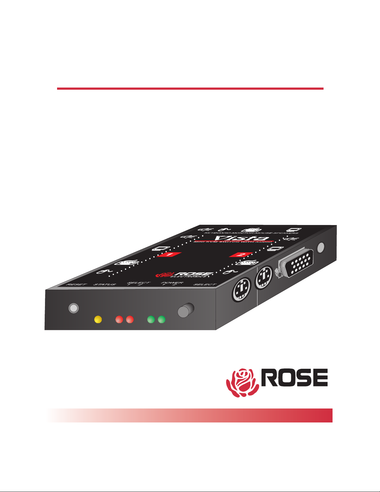
VISTA MINI
DESKTOP KVM SWITCH WITH AUDIO
Installation and
Operation Manual
ELECTRONICS
10707 Stancliff Road n Houston, Texas 77099
Phone: (281) 933-7673 n Internet: www.rosel.com
Page 2

LIMITED WARRANTY
Rose Electronics warrants the Vista MiniTMto be in good working order for one year from the date of
purchase from Rose Electronics or an authorized dealer. Should this product fail to be in good working
order at any time during this one year warranty period, Rose Electronics will, at its option, repair or replace
the Unit as set forth below. Repair parts and replacement units will be either reconditioned or new. All
replaced parts become the property of Rose Electronics. This limited warranty does not include service to
repair damage to the Unit resulting from accident, disaster, abuse, or unauthorized modification of the Unit,
including static discharge and power surges.
Limited Warranty service may be obtained by delivering this unit during the one year warranty period to Rose
Electronics or an authorized repair center providing a proof of purchase date. If this Unit is delivered by mail, you
agree to insure the Unit or assume the risk of loss or damage in transit, to prepay shipping charges to the
warranty service location, and to use the original shipping container or its equivalent. You must call for a return
authorization number first. Under no circumstances will a unit be accepted without a return authorization
number. Contact an authorized repair center or Rose Electronics for further information.
ALL EXPRESS AND IMPLIED WARRANTIES FOR THIS PRODUCT INCLUDING THE WARRANTIES OF
MERCHANTABILITY AND FITNESS FOR A PARTICULAR PURPOSE, ARE LIMITED IN DURATION TO A PERIOD
OF ONE YEAR FROM THE DATE OF PURCHASE, AND NO WARRANTIES, WHETHER EXPRESS OR IMPLIED,
WILL APPLY AFTER THIS PERIOD. SOME STATES DO NOT ALLOW LIMITATIONS ON HOW LONG AN IMPLIED
WARRANTY LASTS, SO THE ABOVE LIMITATION MAY NOT APPLY TO YOU.
IF THIS PRODUCT IS NOT IN GOOD WORKING ORDER AS WARRANTIED ABOVE, YOUR SOLE REMEDY
SHALL BE REPLACEMENT OR REPAIR AS PROVIDED ABOVE. IN NO EVENT WILL ROSE ELECTRONICS BE
LIABLE TO YOU FOR ANY DAMAGES INCLUDING ANY LOST PROFITS, LOST SAVINGS OR OTHER
INCIDENTAL OR CONSEQUENTIAL DAMAGES ARISING OUT OF THE USE OF OR THE INABILITY TO USE
SUCH PRODUCT, EVENIF ROSEELECTRONICS OR AN AUTHORIZED DEALER HAS BEEN ADVISEDOF THE
POSSIBILITY OF SUCH DAMAGES, OR FOR ANY CLAIM BY ANY OTHER PARTY.
SOME STATES DO NOT ALLOW THE EXCLUSION OR LIMITATION OF INCIDENTAL OR
CONSEQUENTIAL DAMAGES FOR CONSUMER PRODUCTS, SO THE ABOVE MAY NOT APPLY TO
YOU. THIS WARRANTY GIVES YOU SPECIFIC LEGAL RIGHTS AND YOU MAY ALSO HAVE OTHER
RIGHTS WHICH MAY VARY FROM STATE TO STATE.
NOTE: This equipmenthas been tested and found to complywith the limits for a Class A digital de
vice, pursuant to Part 15 of the FCC Rules. These limits are designed to provide reasonable pro
-
tection against harmful interference when the equipment is operated in a commercial
environment. This equipment generates, uses, and can radiate radio frequency energy and, if not
installed and used in accordance with the instruction manual, may cause harmful interference to
radio communications. Operation of this equipment in a residential area is likely to cause harmful
interference in whichcase the userwill be requiredto correct theinterference at hisown expense.
© Copyright Rose Electronics 1991-2000. All rights reserved.
No part of this manual may be reproduced, stored in a retrieval system, or transcribed in any form or any
means, electronic or mechanical, including photocopying and recording, without the prior written
permission of Rose Electronics.
IBM ®, AT, and PS/2 are trademarks of International Business Machines Corp.
Microsoft ® and Microsoft Windows™ are registered trademarks of Microsoft Corp.
Rose Electronics Part # MAN-KVT1.1
Printed in the United States of America n Revision 1
Page 3

TABLE OF CONTENTS
INTRODUCTION.......................1
FEATURES .........................1
GETTING STARTED .....................2
Package contents .........................2
Vista Mini models .........................2
Locating the unit ..........................2
Cable requirements ........................2
VIStA MINI HARDWARE ...................4
The front panel...........................4
The connectors ..........................5
INSTALLATION .......................6
Step 1. Connecting monitor, keyboard, mouse, and speakers . . . . 6
Step 2. Connecting the computers ................6
Step 3. Powering up the system..................7
Step 4. Switching from the keyboard ...............7
OPERATION.........................8
Keyboard computer selection ...................8
Going to the next or previous computer ..............8
Scan mode commands ......................8
Scan time interval command ...................9
Mode command ..........................9
Typematic value command ...................10
PS/2 to serial mouse translation, wheel mouse .........11
Keep command .........................11
Null command ..........................11
ROM Identification command ..................12
Reset command .........................12
Reset computer mouse command ................12
Reset to factory default ......................13
KEYBOARD COMMAND SUMMARY .............14
TROUBLESHOOTING....................16
SERVICE INFORMATION ..................16
Page 4

Appendix A. Factory default settings ...........18
Appendix B. General specifications ...........18
Appendix C. Cables and accessories ...........19
Page 5

INTRODUCTION
Thank you for choosing Vista Mini™. Designed for plug-and-play operation,
your new Vista Mini switch simplifies your job by helping you organize your mul
tiple computer applications. Because Vista Mini lets you use a single keyboard,
monitor, mouse, and speakers to access two computers, you can significantly
reduce your equipment overhead and end keyboard and monitor clutter.
FEATURES
Access 2 computers with one keyboard, monitor, mouse, and speakers
n
Low cost and easy to use
n
Small size (.8" high by 3.2" wide by 4.2" deep)
n
Saves physical space, equipment and power costs, reduces clutter
n
Select computer from keyboard command or front panel
n
Simple to use keystrokes switch computers for fast and easy control
n
Front panel has reset switch, status and power LEDs, select LEDs and select switch
n
Uses computer’s power — no external power required
n
Monitor, keyboard, and mouse plug directly into unit
n
Supports all brands of wheel mice
n
Available in two models - computers use DB25 connectors or PC connectors
n
n Scan mode automatically sequences through CPUs at adjustable rate
n Non-volatile memory stores configuration settings
n Heavy-duty steel, fully shielded chassis
n Comes with a one-year warranty and unlimited technical support
n
Made in USA
-
KEYBOARD AND MOUSE
n
Full emulation of keyboard and mouse, computers can be booted at any time
n
Computers can be PS/2 mouse or serial mouse
n
Keyboard Num Lock, Caps Lock, and Scroll Lock states automatically saved and
restored when switching among CPUs
n
Keyboard mode automatically detected
FRONT PANEL
n
Switch to any computer from front panel with select switch
n
Select LEDs show which computer is selected
n
Power LEDs show which computers are powered on
n
Status LED flashes to show keyboard and mouse activity
n
Reset switch reinitializes all devices
VIDEO
n
Video resolution supports up to 1600 x 1280 non-interlaced video
n
Uses amplifiers for crystal clear video and increased distance
1VIStA MINI INSTALLATION AND OPERATION MANUAL
Page 6
GETTING STARTED
To acquaint you with your Vista Mini unit, this manual first describes Vista Mini’s
front and rear panels. Then follow the installation on page 6, which is simply a
description of how to plug in the connectors.
Package contents
Your Vista Mini package includes the Vista Mini unit, your warranty registration
card, and this manual.
Vista Mini models
This manual describes two different models of Vista Mini, see Table 1 below.
The features and commands are the same, the only difference is the connector
type for the computers. Please disregard the diagrams and text that do not apply to your model. The models available are:
Table 1. Vista Mini models
Model Computers Computer connector
KVT-2U 2 PCs DB25 female
KVT-2PC 2 PCs PC (HD15F, MD6F, MD6F, 3.5mm)
Locating the unit
The Vista Mini unit is best located as close to the CPUs as possible. This will re
duce the length of the CPU cables and provide a more cost-effective and neater
installation. While usage of the Vista Mini is trouble-free and transparent and
need not be in an accessible location, you may wish to access the front panel to
observe the LEDs, switch to a computer, or reset the unit.
Cable requirements
Vista Mini connects to each computer with various cables, depending on which
model and computer type, see the next page for the different cable types. You
-
plug the keyboard, monitor, mouse, and speakers directly into Vista Mini. The
cables are most commonly purchased with Vista Mini and will provide quick
and trouble-free operation.
2 VIStA MINI INSTALLATION AND OPERATION MANUAL
Page 7
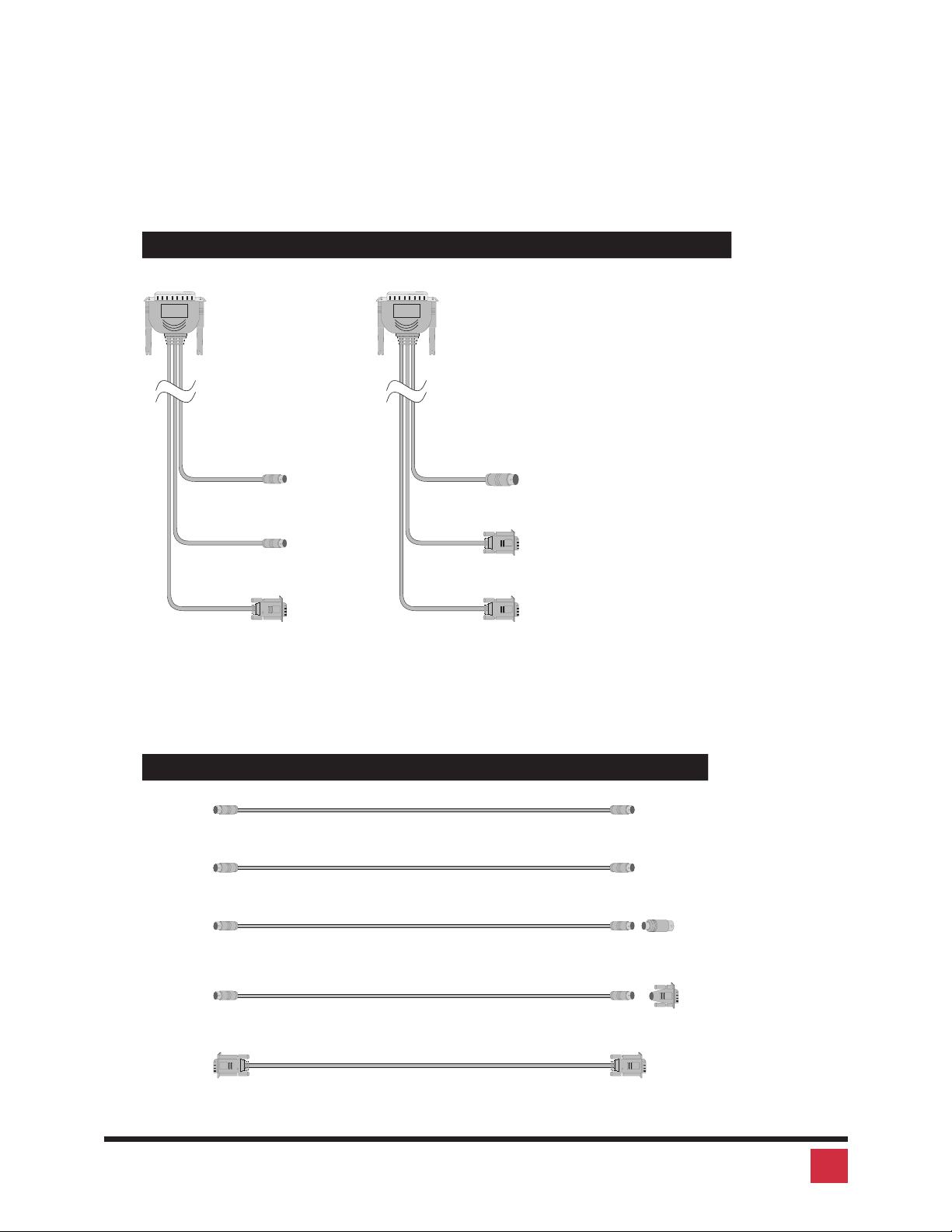
Most installations use cable no longer than 20 feet in length. Cable length will af
fect the quality of the video, depending upon which resolution you will be using.
You can improve the video resolution and distance by ordering coax cables,
see Appendix C for the part number of the cable.
Cables for use with models that have DB25 connectors
To Two Vie w To Two Vie w
-
To PC with mini-din-6
PS/2 mouse port
To PC with mini-din-6
PS/2 mouse port
To VGA video card
Cable to PC computer
with PS/2 keyboard
and PS/2 mouse
CAB-VX0606Cxx (Standard)
CAB-CX0606Cxx (Coax)
To PC with din-5
keyboard port
To PC with DB9 male
serial port
To VGA video card
Cable to PC computer
with AT keyboard
and serial mouse
CAB-VX0509Cxx (Standard)
CAB-CX0509Xxx (Coax)
Cables for use with models that have PC connectors
To
Two View
To
Two View
Cable to PC with PS/2 keyboard CAB-MD6MMxx
CabletoPCwithPS/2mouse CAB-MD6MMxx
To PC with mini-din-6
keyboard port
To PC with mini-din-6
PS/2 mouse port
To
Two View
To
Two View
To
Two View
Cable to PC with AT keyboard
Adapterfrommini-din-6todin-5
Cable to PC with serial mouse
Adapterfrommini-din-6toDB9
Cable to PC with VGA CAB-HD15MMxx (standard)
CAB-MD6MMxx
ACC-KVM6F9F
CAB-MD6MMxx
ACC-MD6FD5M
CAB-C1VMMxx (coax)
To PC with din-5
keyboard port
To PC with DB9
male serial port
To V G A
video card
3VIStA MINI INSTALLATION AND OPERATION MANUAL
Page 8
VIStA MINI HARDWARE
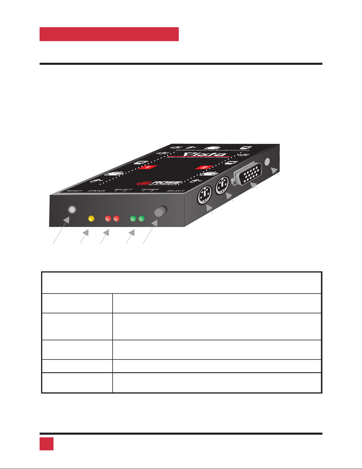
The front panel
The Vista Mini front panel features five LEDs and two switches. To familiarize
yourself with Vista Mini’s controls and indicators, review the illustration and de
scriptions given below.
THIS SIDE CONNECTS
TO KEYBOARD, MOUSE,
MONITOR, AND SPEAKERS
THIS SIDE CONNECTS
TO COMPUTER 1
TO SOUND CARD
ON COMPUTER 2
TO VIDEO CARD
ON COMPUTER 2
TO PS/2 KEYBOARD
ON COMPUTER 2
TO PS/2 MOUSE
ON COMPUTER 2
RESET
SWITCH
STATUS
LED
SELECT
LEDS
POWER
LEDS
SELECT
SWITCH
-
Table 2. The front panel
RESET SWITCH
STATUS LED
SELECT LEDS 1-2
POWER LEDS 1-2
SELECT SWITCH
Resets the unit and initializes the keyboard and mouse, also
used to reset the unit to factory default settings
The yellow status LED lights as data is received from the key
board and mouse. It is off when the keyboard and mouse are
idle.
The red LEDs Indicate which computer is currently selected and
connected to the keyboard, monitor, mouse, and speakers.
The green LEDs show if the computers are powered on.
Selects the computer to connect to the keyboard, mouse, and
monitor.
-
4 VIStA MINI INSTALLATION AND OPERATION MANUAL
Page 9
The connectors
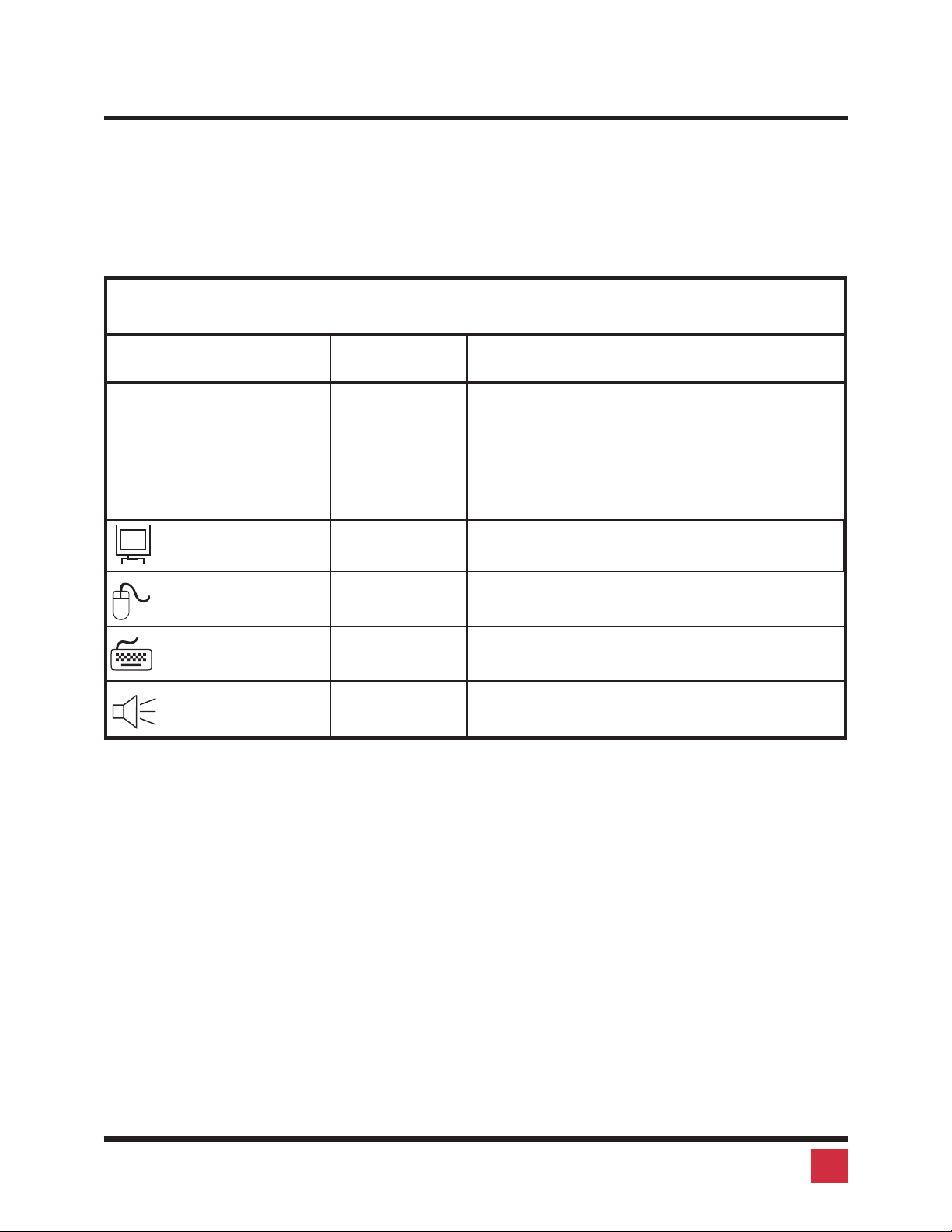
All cables are connected at the Vista Mini’s side and rear panels. The side pan
els are used to connect to the computers. The rear panel is to connect the key
board, monitor, mouse, and speakers. For these you do not need an adapter
cable, since these should plug in directly.
Table 3. The rear panel
Panel Label Connector Description
1,2 DB25 female
or HD15 /
mini-din6
/mini-din 6 /
3.5 mm stereo
jack
VGA MONITOR HD15 female
PS/2 MOUSE Mini-din 6 fe-
male
Computers are connected at these ports us
ing CPU adapter cables. You must have an
adapter cable for each CPU you plan to con
nect.
Connect the VGA monitor directly to this
connector.
Connect the PS/2 mouse directly to this connector.
-
-
-
-
PS/2 KEYBOARD Mini-din 6 fe-
male
SPEAKERS 3.5mm stereo
jack
Connect the keyboard directly to this connector.
Connect the speakers, either powered or
unpowered to this jack.
5VIStA MINI INSTALLATION AND OPERATION MANUAL
Page 10

INSTALLATION
Step 1. Connecting monitor, keyboard, and mouse
1.1 Plug the monitor, keyboard, mouse, and speaker cables directly into
the rear panel of the unit.
Step 2. Connecting the computers
CPU cables connect your computers to Vista Mini. Each computer requires its
own cables, with appropriate connectors for your particular CPU. CPU cables
are available from Rose Electronics. Refer to page 3 for using the proper cable.
For Vista Mini models with DB 25 connectors:
2.1 Plug the DB25 male connector of the CPU adapter cable into one of the
numbered CPU ports on the Vista Mini side panel.
2.2 Plug the CPU adapter cable’s monitor, keyboard, and mouse connectors into the CPU’s corresponding ports.
For Vista Mini models with PC connectors:
2.1 Plug the HD15 male-male cable from the video card into one of the
numbered HD15 female connectors on the Vista Mini rear panel.
2.2 Plug the mini-din-6 male-male cable from the computer keyboard port
into one of one of the numbered mini-din-6 female connectors with a
keyboard symbol on the Vista Mini rear panel. If your computer has a
din-5 keyboard port use the mini-din-6 female to din-5 male adapter.
2.3 Plug the mini-din-6 male-male cable from the computer mouse port
into one of one of the numbered mini-din-6 female connectors with a
mouse symbol on the Vista Mini rear panel. If your computer has a se
rial port for the mouse use the mini-din-6 female to DB9 female adapter.
Warning do not substitute with a non-Rose adapter, there is a differ
ence, damage may occur if you use a third-party adapter!!!
2.4 Plug the 3.5mm stereo cable into the stereo jack.
-
-
6 VIStA MINI INSTALLATION AND OPERATION MANUAL
Page 11

WARNING: Avoid routing cable near fluorescent lights, air conditioning
compressors, or machines that may create electrical noise. For best quality
video, when exceeding 20 feet use coax cable. Appendix A, B, and E for fur
ther cable information.
Step 3. Powering up the system
-
3.1 Boot up each of the connected CPUs. Vista Mini emulates all key
board and mouse functions for automatic boot-up. You do not have
to re-boot the CPU, if it is inconvenient. In this case you may need to
issue the mode command, see page 9, to have proper keyboard
communication.
Step 4. Switching from the keyboard
Your Vista Mini is now ready for operation using its default settings. Pressing the
numbered switch on the front panel will switch to that computer. To take full advantage of the Vista Mini features, refer to the Operation section beginning on
page 8 The Operation section gives detailed information about each of the Vista
Mini commands, describing its application and giving the keyboard command
sequence. For your convenience, this information is summarized in the Key-
board command summary on page 14. To begin switching immediately from
the keyboard follow the instructions below.
4.1 Press and release your keyboard’s left Control Key (<Ctrl>), then
-
type in the computer number 1-2.
NOTE: Before entering any Vista Mini keyboard command, you must press
and release the left Control Key. This activates Vista Mini to look for com
mands from the keyboard. You then have two seconds in which to start en
tering a valid command.
NOTE: When entering numeric commands, use only the numeral keys
located at the top of your alpha-numeric keyboard. Numbers entered from
the numeric keypad to the right will not be recognized asvalid commands.
-
-
7VIStA MINI INSTALLATION AND OPERATION MANUAL
Page 12

OPERATION
Vista Mini is simple to operate. Computer selection and function commands are
entered from the keyboard. You can also select computers manually from the
Vista Mini’s front panel by using switches 1-4. This section details each Vista
Mini function.
IMPORTANT OPERATION NOTE: To send Vista Mini keyboard com
mands, you must first press and release the left Control Key (<Ctrl>).
Pressing and releasing <Ctrl> activates Vista Mini to look for commands
from the keyboard. You have two seconds between each keystroke to enter
a valid command, otherwise Vista Mini aborts the command.
NOTE: When entering numeric commands, use only the numeric keys lo
cated at the top of your keyboard. Numbers entered from the numeric key
pad to the right will not be recognized as valid commands.
NOTE: Vista Mini commands ignore case. All command letters are shown
capitalized for clarity only.
-
-
-
Keyboard computer selection
To select a computer from your keyboard, press and release your keyboard’s
left Control Key (<Ctrl>), then type in the computer number. Remember to use
the numbers located at the top of your keyboard. Do not use the numeric keypad.
Going to the other computer
From the keyboard you can switch to the other computer by selecting either the
Next or Previous computer. To go to the Next computer, press and release the
left Control Key <Ctrl>, then press the “+/=” (plus) key. To go to the Previous
computer, press and release <Ctrl>>, then press the “-/_” (minus) key. The
command is not case-sensitive. Use the keys at the top of your keyboard, not
those on the numeric pad.
Scan mode commands
To enable scanning from the keyboard, press and release the left Control Key
(<Ctrl>), then type “S”. Vista Mini will begin scanning sequentially from its cur
rent computer to the next computer, then begin again. The time between
switching to the next computer is the scan time interval (see below) and is pro
8 VIStA MINI INSTALLATION AND OPERATION MANUAL
-
-
Page 13

grammable from 1-15 seconds. To stop scanning, press and release <Ctrl>,
then type “X”. Scanning is also disabled by entering a computer selection com
mand. The power-on state of scanning can be saved in non-volatile memory. To
do this set the scan state and follow with the Keep command.
Scan time interval command
The scan time interval command sets the time, in seconds, that Vista Mini will
pause at each of the computers when scanning. The default setting is 5 sec
onds. To set another interval, press and release the left Control Key, type “T”,
enter the new scan time interval (in seconds), and press <Enter>. Remember
to use the upper numeric keys, not the numeric keypad to the right. Follow with
the Keep command to save the setting.
Mode command
Vista Mini supports keyboard modes 1, 2, and 3. The keyboard mode is set by
commands from the CPU. Mode 2 is the most common mode used by the vast
majority of PCs. It is also the power-up state of all PC and PS/2 keyboards.
-
-
Mode 1 is used primarily by older IBM PS/2 models. Mode 3 is used by many
Unix workstations, such as SGI, HP, DEC, RS 6000, and others.
Vista Mini automatically detects each CPU’s keyboard mode upon CPU
boot-up, and thus learns which CPU uses which mode. If the CPU has already
booted and is then connected, Vista Mini cannot detect the CPU’s keyboard
mode and uses the setting stored in the Vista Mini’s non-volatile memory. The
mode command can be issued to change the keyboard mode for each com
puter and can be saved in non-volatile memory with the Keep command.
To issue the Mode command, press and release the left Control Key, type ‘M“,
and enter the mode number ”1“, ”2“, or ”3“ followed by <Enter>. Remember to
use the alpha-numeric keys, not the numeric keypad, to enter the mode num
ber. Follow with the Keep command. The mode is changed on your currently
selected computer. To change the mode on another computer, you must first
switch to that computer and then issue the mode command.
Typematic value command
-
-
Vista Mini can be configured to control the keyboard typematic rate and delay.
This setting is used to adjust the user preference of the way the keyboard acts
9VIStA MINI INSTALLATION AND OPERATION MANUAL
Page 14
when holding a key down to repeat the key, such as when moving a cursor
across a line. The rate is the speed at which the keys are sent in keys/second.
The delay is the wait time in milliseconds after the key is initially pressed, before
additional keystrokes are sent. To issue the command press and release the
left Control key, then type “A”, then enter the 1-3 digit decimal typematic value
followed by <Enter>. The typematic value is defined as shown below. Use the
keep command to save the value.
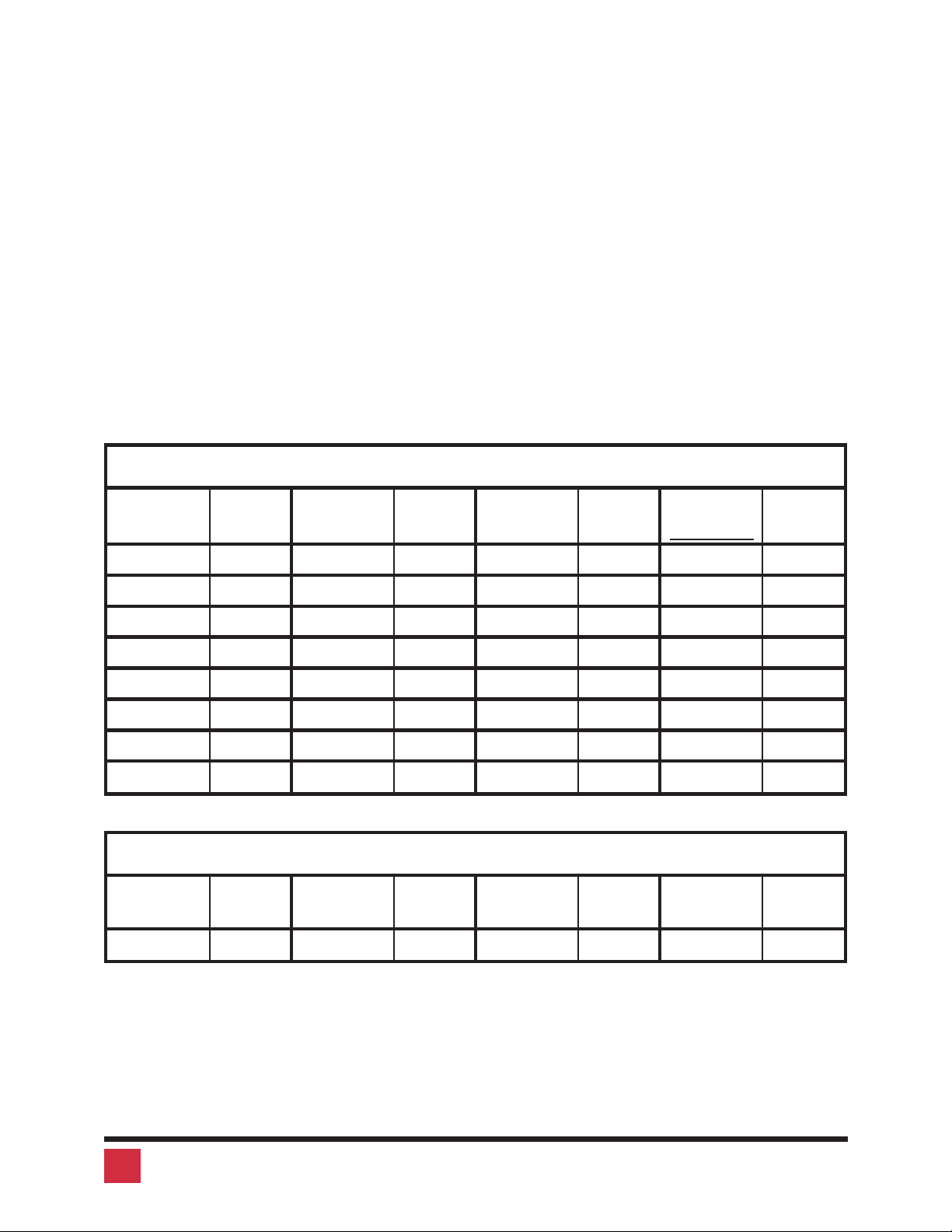
The typematic value to be used is determined from the following tables using the
equation: Typematic Value = Rate value + Delay Value. Pick the desired rate
in keys/sec. (32 choices) and delay in milliseconds (4 choices) from the tables
below. Add the values to the right of the desired settings. For example to use a
Rate of 16.0 keys/sec. and a 500 millisecond delay, the typematic value=7+
32 = 39, so to set this value, type <Ctrl> A 39 <Enter>.
Table 4. Typematic rate
Rate
Keys/sec
Rate
Value
Rate
Keys/sec
Rate
Value
Rate
Keys/sec
Rate
Value
Rate
Keys/sec
Rate
Value
30.0 0 15.0 8 7.5 16 3.7 24
26.7 1 13.3 9 6.7 17 3.3 25
24.0 2 12.0 10 6.0 18 3.0 26
21.8 3 10.9 11 5.5 19 2.7 27
20.0 4 10.0 12 5.0 20 2.5 28
18.5 5 9.2 13 4.6 21 2.3 29
17.1 6 8.6 14 4.3 22 2.1 30
16.0 7 8.0 15 4.0 23 2.0 31
Table 5. Typematic delay
Delay in
millisec.
Delay
value
Delay in
millisec.
Delay
value
Delay in
millisec.
Delay
value
Delay in
millisec.
Delay
value
250 0 500 32 750 64 1000 96
10 VIStA MINI INSTALLATION AND OPERATION MANUAL
Page 15

PS/2 to serial mouse translation, wheel mouse
You can use some computers with PS/2 mouse interfaces and some computers
with serial interfaces. You must issue this command on each computer which is
serial. You must switch to each computer and issue the command.
To configure a computer for a serial mouse, press and release the left Control
Key, type “Q1”, and press <Enter>. Follow with the Keep command to save
the new setting in the unit’s non-volatile memory. To restore a computer which
was previously set to serial to regular PS/2 use Q0 instead of Q1.
Whether a computer uses a PS/2 wheel mouse or a regular PS/2 mouse is
learned by Vista when the computer loads its mouse driver. This will override
any previous setting. You can tell Vista to change its PS/2 communication to
regular or wheel with the Q command. You can also save it to non-volatile mem
ory.
To configure a computer for a wheel mouse, press and release the left Control
Key, type “Q2”, and press <Enter>. Follow with the Keep command to save
the new setting in the unit’s non-volatile memory. To restore a computer which
was previously set to wheel mouse to regular PS/2 use Q0 instead of Q2.
Keep command
The Keep command saves the current state of the Vista Mini’s custom settings.
These settings are scan enable, scan interval, each CPU’s mode and keyboard
LED state, maximum computers, the keyboard typematic value, and the mouse
translation for each CPU. These settings are saved in non-volatile memory and
become the power-up settings. To enter the command, press and release the
left Control Key, then type “K”.
Null command
-
This command is used to re-synchronize an out-of-sync PS/2 mouse. Such a
condition can result due to transients, spurious power-up effects, or plugging
and unplugging of cables with live equipment. The command may need to be
entered once or twice, depending if the mouse is out-of-sync by one or two
bytes. Microsoft mouse driver version 9.01 or later corrects this inadequacy of
previous drivers and renders this command unnecessary. To issue the com
mand, press and release the left Control Key, then type “N”.
11VIStA MINI INSTALLATION AND OPERATION MANUAL
-
Page 16

ROM Identification command
This command is used to identify the revision level of Vista Mini firmware cur
rently installed. Before entering this command, your currently selected CPU
should be at a command prompt, word processor, or editor, so that when the
Vista Mini sends the ROM revision level that the result will be displayed. To issue
the command, press and release the left Control Key, then type “I”. Vista Mini
will send back its current firmware revision level, in the format
majorlevel.minorlevel.
Reset command
This command is used to re-boot the mouse and keyboard without removing
power from the Vista Mini. This is most useful to reset a PS/2 mouse which has
been unplugged and plugged back in. This command is also useful to enable
mouse data to be sent to a CPU which has not enabled the mouse. This may be
the case if the Vista Mini was not connected or powered off after a CPU was
booted up. To issue the command, press and release the left Control Key, then
type “R”. This command should not be issued to a CPU which has a PS/2
mouse connected, but no mouse driver is loaded, since many CPUs will crash if
-
you send them unexpected mouse data.
Immediately upon issuing the command, you will see the keyboard LEDs all go
on and then resume their previous state.
Reset computer mouse command
This command sends a mouse reset command to the currently selected com
puter. Don’t confuse this command with the reset command which resets the
mouse itself. This command can be used to recover a stuck mouse on NT. To is
sue the command, press and release the left Control Key, then type “O”.
Do not use this on older computers which can not recover the mouse by plug
ging a mouse in directly as it will make the mouse go out of sync.
Reset to factory default
The settings that have been previously set and saved in non-volatile memory
-
-
-
can be returned to their factory default settings. This can be useful when the unit
is being moved to a new installation or to put the settings into a known condi
12 VIStA MINI INSTALLATION AND OPERATION MANUAL
-
Page 17

tion. To perform this operation, hold in the “1" switch on the front panel and
press and release the ”reset" switch. At least one CPU must be connected to the
unit, so that the unit can be powered. The status LED will flash three times to sig
nify that the non-volatile memory has been returned to the original factory de
fault settings listed in Appendix A.
-
-
13VIStA MINI INSTALLATION AND OPERATION MANUAL
Page 18
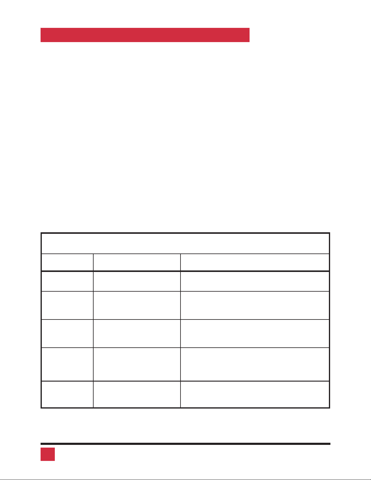
KEYBOARD COMMAND SUMMARY
To enter any keyboard command, first press and release the left Control Key,
represented by <Ctrl>. Then enter the command followed by any parameters
you wish to specify, for example the computer number.
Letter commands are not case sensitive, and are shown in upper case for clarity
only.
Do not use the numeric keypad to enter any commands.
All Vista Mini commands use a two second time-out between characters, to
abort the command. This is a feature that restores the keyboard to normal oper
ation, so the keyboard is not put it into a command mode which might lock it up
from normal operation.
The <Ctrl> character is always passed through to the CPU. The command
characters and command operands, however, are absorbed by the Vista Mini
and not sent to the CPU.
Table 6. Keyboard command summary
Command Key Sequence Description
Connect to
computer
Connect to
next com
puter
-
<Ctrl> x
where x is 1, or 2
<Ctrl> +
Connects your common keyboard, monitor,
and mouse to the selected computer.
Selects the other computer.
-
Connect to
previous
computer
Scan On <Ctrl> S
Scan Off <Ctrl> X
<Ctrl> -
Selects the other computer
Turns Scan mode on, causing Vista Mini to
start scanning sequentially from the current
port through the remaining ports and begin
ning again at Port 1.
Turns Scan mode off.
Note: Scan can also be stopped by entering
a port selection command.
-
14 VIStA MINI INSTALLATION AND OPERATION MANUAL
Page 19

Reset com
mand
-
<Ctrl> R
Resets and enables mouse and keyboard,
enables PS/2 mouse on currently selected
port.
Send null to
mouse
Reset com
puter mouse
Identify ROM
version
Keep settings <Ctrl> K
Scan time in
terval
Set keyboard
mode
Set typematic
value
<Ctrl> N
<Ctrl> O (alpha not
zero)
<Ctrl> I
<Ctrl> T xx <Enter>
where xx is time in sec
onds from
1-15 seconds
Select port, then enter
command:
<Ctrl> M x <Enter>
where x is 1, 2, or 3
<Ctrl> A xxx <Enter>
where xxx is a
1–3 digit number’ from 0
to 127 indicating KB
typematic value
Used to re-synchronize PS/2 mouse which
has gotten out-of-sync.
Used to reset computer’s mouse
Identifies ROM version, CPU must be at
some sort of command prompt to receive
value.
Tells Vista Mini to save current scan state
and custom settings of commands shown
below.
Sets the time, in seconds, that Vista Mini will
pause at each port when scanning.
-
Note: Follow with Keep command.
Sets Vista Mini CPU’s keyboard mode. Used
when CPU is booted before being connected to Vista Mini.
Note: Follow with Keep command.
Sets power-on keyboard typematic action
which is controlled by the Vista Mini. This can
be used to adjust the key stroke rate and delay to the user preferred setting. See Tables 4
and 5 for how the typematic value is determined.
Note: Follow with Keep command.
Set mouse
type
Select port, then enter
command <Ctrl> Q x
<Enter>
where x is a 0 for a regu
lar PS/2 mouse, 1 for a
serial mouse, and 2 for a
PS/2 wheel mouse.
Enable/disable PS/2 to serial mouse translation. Must be done for each computer
where translation is desired by switching to
-
it and issuing the command.
Also enables/disables wheel mouse com
munication. Issue the command for each
computer which has a wheel mouse.
Requires a PS/2 mouse.
Note: Follow with Keep command.
-
15VIStA MINI INSTALLATION AND OPERATION MANUAL
Page 20

TROUBLESHOOTING
1. CPU does not boot, keyboard error received
a. Cable is loose, reseat cable and hit F1 to continue or reboot com
puter.
b. Wrong cable plugged in, keyboard and mouse cables reversed.
c. Cable is defective, try using cable from another CPU. If problem
goes away cable is defective.
d. Port on Vista Mini is defective, try using another port on Vista Mini. If
problem goes away port is defective.
e. Port on CPU is defective, try plugging in keyboard or mouse di
rectly if problem remains CPU port is defective. If power LED not lit
when switched to computer which is power on, fuse on computer’s
motherboard may be blown.
2. Mouse driver does not load.
a. If PS/2 type mouse, CPU must be connected to Vista Mini or mouse
at boot-up time in order for mouse to be recognized by CPU. Re-
boot computer with Vista Mini powered on and cable attached.
b. If RS-232 type mouse, make sure right COM port is being used and
syntax of mouse driver is correct to search for the correct port.
c. Incompatible or old mouse driver being used, try latest driver. At
time of this publishing Microsoft 9.01 or later driver is best one
available.
-
-
d. Mouse translation set incorrectly, see page 11.
3. Can’t switch ports from keyboard
a. You must press and release the left control key before you press
the key which specifies the port number. You must also use the nu
meric keys above the alphabetic keys, not those on the numeric
keypad.
4. Wrong or missing characters from those typed
a. The mode of the keyboard does not match that of the CPU. Issue
the mode command, usually 1 for IBM PS/2s and 2 for all others.
The default setting of the Vista Mini is mode 2. Sometimes an incor
rect mode will confuse the CPU or keyboard and require re-booting
the CPU or resetting the keyboard by unplugging and plugging it
back in.
5. Mouse does not move
a. Vista Mini turned off after or not connected when CPU was booted
or the application using the mouse was run. Exit and re-enter appli
cation or operating system using mouse or issue reset command.
-
-
-
16 VIStA MINI INSTALLATION AND OPERATION MANUAL
Page 21

b. PS/2 mouse was not connected when Vista Mini powered up or has
been disconnected and reconnected. Issue the reset command.
c. Mouse translation set incorrectly, see page 11.
6. PS/2 mouse gets out of sync
a. Cabling was disturbed during mouse movement. Issue the null
command once or twice to re-sync the mouse. Get a later mouse
driver which does not exhibit this problem, such as Microsoft rev
9.01 or later.
7. Video fuzzy
a. Cable too long or wrong type. Use coax cable for high resolution.
8. Video not synchronized or wrong color
a. Cable is loose, reseat cable.
b. Wrong CPU cable used. If you have a 9515, 9517, 9518, XGA mono
or similar monitor you must use special cables or adapters.
c. Cable is defective, try using cable from another CPU if problem
goes away cable is defective.
d. Port on Vista Mini is defective, try using another port on Vista Mini. If
problem goes away port is defective.
9. Lower resolution video OK, but can’t enter high resolution mode
a. Wrong CPU cable used.
b. Driver has not been setup. Windows, OS/2, or other driver has not
been configured for this resolution. Configure the driver.
SERVICE INFORMATION
Maintenance and repair
The unit does not contain any user-serviceable parts inside. Any malfunction of
the unit should be reported to a factory-authorized repair center for service. Any
discrepancies in the operation of the unit according to this manual should be re
ported to the Technical Support Department of Rose Electronics.
-
17VIStA MINI INSTALLATION AND OPERATION MANUAL
Page 22
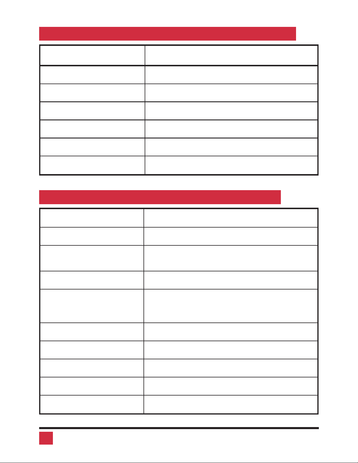
APPENDIX A. FACTORY DEFAULT SETTINGS
Setting Default
Scan enable Off
Scan Time Interval 5 seconds
Caps/Numlock/Scroll Numlock On
Keyboard Mode 2
Typematic Value 43 (Rate=10.9 chars/sec, delay = 500 millisec.)
Mouse translation 0 (PS/2 mouse input to PS/2 mouse output)
APPENDIX B. GENERAL SPECIFICATIONS
SIZE .8" high by 3.2" wide by 4.2" deep
WEIGHT 1 lb.
ENVIRONMENT 0 to 55°C., 0% to 80% non-condensing
relative humidity
INPUT POWER Supplied by computers
CPU CONNECTORS KVT-2U DB25 Female
KVT-2PC HD15F/MD6F/MD6F/3.5 mm
jack
VIDEO CONNECTOR HD15 female VGA video
PS/2 MOUSE CONNECTOR Mini-din 6 female
KEYBOARD CONNECTOR Mini-din 6 female
AUDIO CONNECTOR 3.5 mm stereo jack
CHASSIS Fully shielded, black painted steel
18 VIStA MINI INSTALLATION AND OPERATION MANUAL
Page 23
CONTROLS Reset switch, computer select switch
INDICATORS Status LED, computer select LEDs 1-2, computer
power LEDs 1-2
APPENDIX C. CABLES
Description Part Number
CPU adapter cables for models with DB25 connectors
VGA–PS/2 keyboard–PS/2 mouse to DB25M CAB-VX0606Cxx*
VGA–AT keyboard–Serial (9) mouse to DB25M CAB-VX0509Cxx*
Coax VGA-PS/2 keyboard–PS/2 mouse to DB25M CAB-CX0606Cxx**
Coax VGA-AT keyboard–Serial (9) mouse to DB25M CAB-CX0509Cxx**
CPU cables for models with PC connectors
VGA male-male cable CAB-HD15MMxx*
Coax VGA male-male cable CAB-C1VMMxx*
Mini-din-6 male-male cable CAB-MD6MMxx*
Mini-din-6 female to din-5 male adapter ACC-MD6FD5M
Mini-din-6 female to DB9 female adapter ACC-KVM6F9F
*Available in standard lengths of 1, 5, 10, and 20 feet
Replace xx with desired length.
**Available in 1, 5, 10, 20, 35, 50, 75, and 100 foot lengths.
Replace xx with desired length.
19VIStA MINI INSTALLATION AND OPERATION MANUAL
Page 24

ELECTRONICS
10707 Stancliff Road n Houston, Texas 77099
Phone: (281) 933-7673 n Internet: www.rosel.com
 Loading...