

Page 1
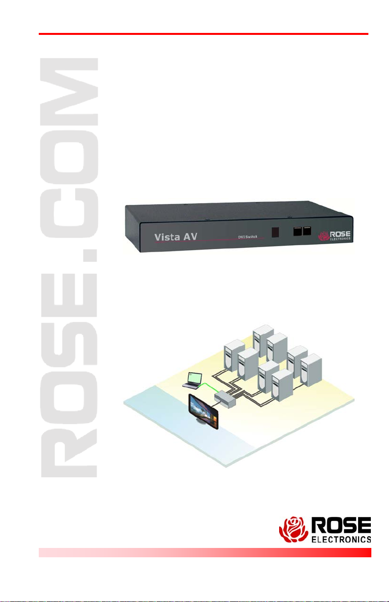
Vista AV DVI SWITCH
IN S TAL LATION AND
OPERATIONS
MANUAL
10707 Stancliff Road Phone: (281) 933-7673
Houston, Texas 77099 WWW.ROSE.COM
Page 2

Page 3

LIMITED WARRANTY
Rose Electronics® warrants the Vista AV DVI switch to be in good working order for one year
from the date of purchase from Rose Electronics or an authorized dealer. Should this product
fail to be in good working order at any time during this one-year warranty period, Rose
Electronics will, at its option, repair or replace the Unit as set forth below. Repair parts and
replacement units will be either reconditioned or new. All replaced parts become the property of
Rose Electronics. This limited warranty does not include service to repair damage to the Unit
resulting from accident, disaster, abuse, or unauthorized modification of the Unit, including
static discharge and power surges.
Limited Warranty service may be obtained by delivering this unit during the one-year warranty
period to Rose Electronics or an authorized repair center providing a proof of purchase date. If
this Unit is delivered by mail, you agree to insure the Unit or assume the risk of loss or damage
in transit, to prepay shipping charges to the warranty service location, and to use the original
shipping container or its equivalent. You must call for a return authorization number first. Under
no circumstances will a unit be accepted without a return authorization number. Contact an
authorized repair center or Rose Electronics for further information.
ALL EXPRESS AND IMPLIED WARRANTIES FOR THIS P RO DUCT INCL UDI NG T HE
WARRANTIES OF MERCHANTABILITY AND FITNESS FOR A PARTICULAR PURPOSE,
ARE LIMITED IN DURATION TO A PERIOD OF ONE YEAR FROM THE DATE OF
PURCHASE, AND NO WARRANTIES, WHETHER EXPRESS OR IMPLIED, WILL APPLY
AFTER THIS PERIOD. SOME STATES DO NOT ALLOW LIMITATIONS ON HOW LONG AN
IMPLIED WARRANTY LASTS, SO THE ABOVE LIMITATION MAY NOT APPLY TO YOU.
IF THIS PRODUCT IS NOT IN GOOD WORKING ORDER AS WARRANTED ABOVE, YOUR
SOLE REMEDY SHALL BE REPLACEMENT OR REPAIR AS PROVIDED ABOVE. IN NO
EVENT WILL ROSE ELECTRONICS BE LIABLE TO YOU FOR ANY DAMAGES INCLUDING
ANY LOST PROFITS, LOST SAVINGS OR OTHER INCIDENTAL OR CONSEQUENTIAL
DAMAGES ARISING OUT OF THE USE OF OR THE INABILITY TO USE SUCH PRODUCT,
EVEN IF ROSE ELECTRONICS OR AN AUTHORIZED DEALER HAS BEEN ADVI SE D OF
THE POSSIBILITY OF SUCH DAMAGES, OR FOR ANY CLAIM BY ANY OTHER PARTY.
SOME STATES DO NOT ALLOW THE EXCLUSION OR LIMITATION OF INCIDE NTAL O R
CONSEQUENTIAL DAMAGES FOR CONSUMER PRODUCTS , SO T HE AB OVE MAY NOT
APPLY TO YOU. THIS WARRANTY GIVES YOU SPECIFIC LEGAL RIGHTS AND YOU MAY
ALSO HAVE OTHER RIGHTS WHICH MAY VARY FROM STATE TO STATE.
NOTE: This equipment has been tested and found to comply with the limits for a Class A digital
device, pursuant to Part 15 of the FCC Rules. These limits are designed to provide reasonable
protection against harmful interference when the equipment is operated in a commercial
environment. This equipment generates, uses, and can radiate radio frequency energy and, if
not installed and used in accordance with the instruction manual, may cause harmful
interference to radio communications. Operation of this equipment in a residential area is likel y
to cause harmful interference in which case the user will be required to correct the interference
at his own expense.
IBM, AT, and PS/2 are trademarks of International Business Machines Corp. Microsoft and
Microsoft Windows are registered trademarks of Microsoft Corp. Any other trademarks
mentioned in this manual are acknowledged to be the property of the trademark owner.
Copyright Rose Electronics 2010 All rights reserved.
No part of this manual may be reproduced, stored in a retrieval system, or transcribed in any form or any
means, electronic or mechanical, including photocopying and recording, without the prior written permission
of Rose Electronics.
Rose Electronics Part # MAN-VISAV
Printed In the United States of America – 1.0
Page 4

TABLE of CONTENTS
Contents Page #
System Introduction ....................................................................................... 1
About this manual .......................................................................................... 1
Product Registration ...................................................................................... 1
Disclaimer ...................................................................................................... 1
Features ......................................................................................................... 2
Package contents ....................................................................................... 2
Rose Electronics web site .......................................................................... 2
Vista AV Models ............................................................................................ 3
Vista AV Installation ....................................................................................... 4
System Operation .......................................................................................... 5
Front panel control ..................................................................................... 5
Remote Serial Switching ............................................................................ 6
DDC Information / Learning ....................................................................... 6
Service ........................................................................................................... 7
Technical Support .......................................................................................... 7
Figure Page #
Figure 1. Models ............................................................................................ 3
Figure 2. Typical Installation .......................................................................... 4
Figure 3. Front Panel ..................................................................................... 5
Appendices Page #
Appendix A - Specifications ........................................................................... 9
Appendix B – Part numbers ......................................................................... 10
Page 5

INTRODUCTION
System Introduction
Thank you for choosing the Vista AV from Rose Electronics for your DVI
video switching applications. The Vista AV is a very versatile product that
can switch the DVI-D inp ut s ignals from your PC or Mac computers to a
common DVI monitor. Selection can be made using the front panel push
buttons or by sending commands from a controlling computer to the RS232
port on the unit.
The Vista AV is available in four models, the 1x2, 1x4, 1x8, and 1x16. All
models operate and function in the same manor. When the input DVI-D
video source is selected, it is instantly displayed on the output DVI monitor
at resolutions up to 1920 x 1200.
About this manual
This manual covers the installation, configuration, and the operation of the
Vista DVI switching system. The system consists of the Vista DVI unit, the
connected computers, the output DVI monitor, and a computer to send
switching commands to the unit. The Installation section describes how all
components are interconnected to form a seamless video switching system.
Product Registration
Register your product for future updates at: www.rose.com/htm/onlineregistrationform.htm.
Disclaimer
While every precaution has been taken in the preparation of this manual, the
manufacturer assumes no responsibility for errors or omissions. Neither
does the manufacturer assume any liability for damages resulting from the
use of the information contained herein. The manufacturer reserves the
right to change the specifications, functions, or circuitry of the product
without notice.
The manufacturer cannot accept liability for damages due to misuse of the
product or other circumstances outside the manufacturer’s control. The
manufacturer will not be responsible for any loss, damage, or injury arising
directly or indirectly from the use of this product.
Vista AV Installation and Operations Manual 1
Page 6

Features
Models available with:
1 DVI-D output / 2 DVI-D video input ports
1 DVI-D output / 4 DVI-D video input ports
1 DVI-D output / 8 DVI-D video input ports
1 DVI-D output / 16 DVI-D video input ports
Front panel push-buttons or remote serial port switching
Multi-platform support for:
Windows
Mac
Linux
Sun
DVI-D Single Link Resolution up to 1920 x 1200 @ 60Hz
DVI input cable length – 20 feet*
DVI output cable length – 20 feet*
Front panel display indicates the active selection
No configuration needed, connect the hardware and its ready to use
Plug-and-play, no unit configuration needed
* If your system layout requires your monitors to be more than 15 feet
from the Vista AV unit, use a high quality DVI cable. For distances
greater than 20 feet, Rose Electronics DVI extender units can be
interfaced to extend the distance up to 400 feet over CATx cable or
up to 33,000 feet over singlemode fiber cable.
®
PC’s
Package contents
Vista AV model as ordered
Power adapter for the model ordered
Documentation CD
Cables are usually ordered separately. If the package contents are not
correct, contact Rose Electronics or your reseller so the problem can be
quickly resolved.
Rose Electronics web site
Visit our web site at www.rose.com for additional information on the Vista AV
and other products offered by Rose Electronics that are designed for data
center applications, classroom environments, and many other access and
switching applications.
2 Vista AV Installation and Operations Manual
Page 7
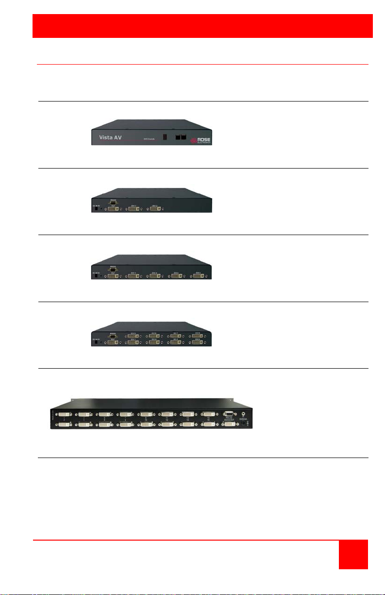
MODELS
Front View
Selection Indicator
Rear View 1x2 Model
2-DVI-D inputs
Rear View 1x4 Model
4-DVI-D inputs
Rear View 1x8 Model
8-DVI-D inputs
Rear View 1x16 Model
bracket
Vista AV Models
The Vista AV is available in the following models:
Scroll up button
Scroll down button
Power adapter input
RS232 port
1-DVI-D output
Power adapter input
RS232 port
1-DVI-D output
Figure 1. Models
Power adapter input
RS232 port
1-DVI-D output
Power adapter input
RS232 port
1-DVI-D output
16-DVI-D inputs
Built-in Rack mount
Vista AV Installation and Operations Manual 3
Page 8
INSTALLATION
Vista AV Installation
Installation of the Vista AV Switch is a very easy and simple procedure.
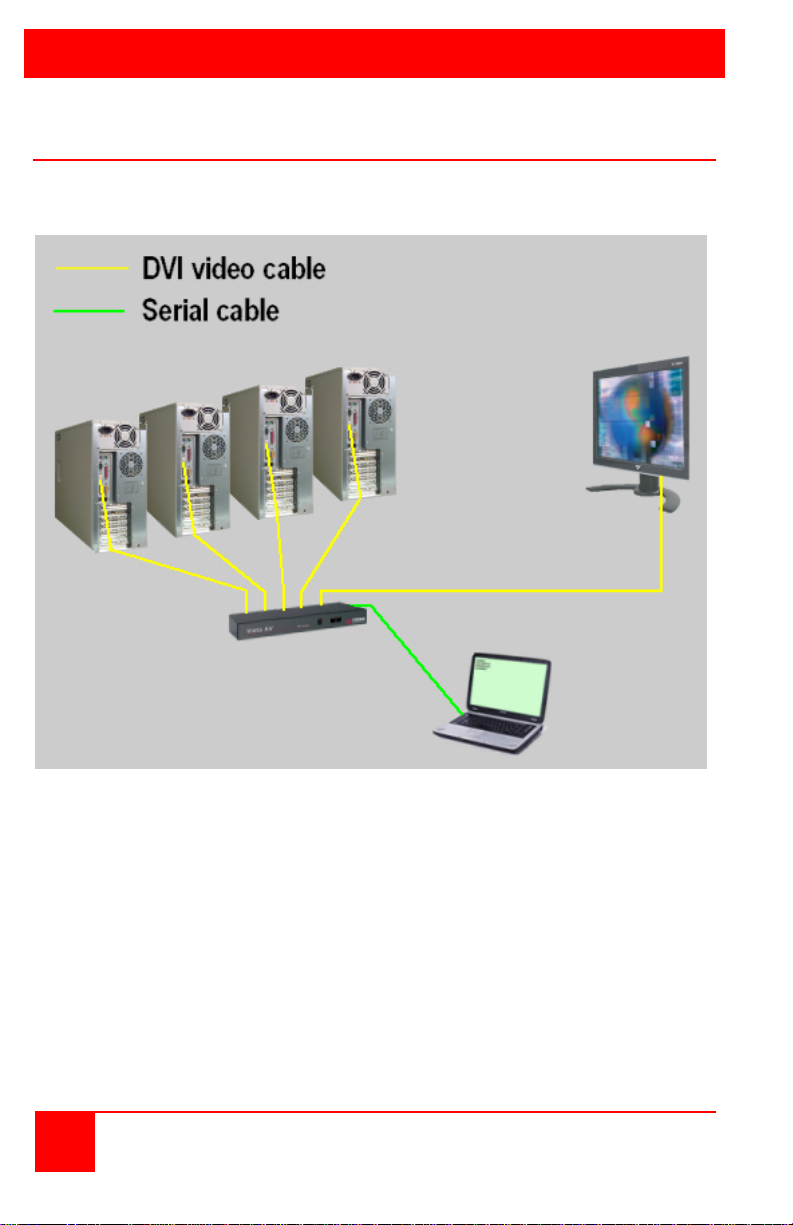
Figure 2 shows a typical installation. All models install in the same manor.
Figure 2. Typical Installation
1. Connect each computers DVI video port to the
corresponding DVI Video input ports on the unit.
2. Connect a DVI monitor to the video out connector.
3. Connect a standalone or laptop computer or controller
to the RS232 port.
4. Connect the provided power adapter to the Vista AV units
power jack on the rear panel.
No configuration or set-up is needed.
Each model installs in the same manor.
4 Vista AV Installation and Operations Manual
Page 9
OPERATION
System Operation
Front panel control
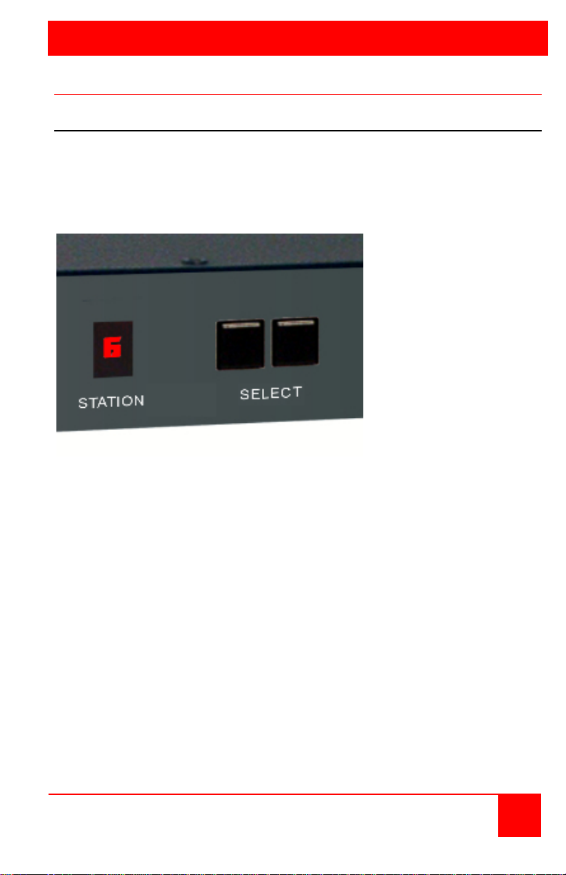
Figure 3 shows the front panel select buttons and the station indicator.
The select buttons sequentially select (scroll up or down) which DVI input
signal to route to the DVI output. The station indicator shows which DVI
input port is selected.
Figure 3. Front Panel
Vista AV Installation and Operations Manual 5
Page 10
Mode
Indicator
Description of mode
P
A “P” indicates Personal Computer Mode. This selection
works for any PC / Display combination.
A
An “A” indicates Apple Mode. This selects the best display
mode to accommodate a Mac computer
S
An “S” indicates Screen Mode. This mode replicates the type
of device connected to input port #1.
Remote Serial Switching
All Vista AV models can be remotely switched using the RS-232 connection.
Install and connect the unit as shown in Figure 2. Use a DB9 male-tofemale serial cable to connect a remote computer or laptop to the Vista AV’s
RS-232 port. Use a serial communication program like HyperTerminal to
connect to the Vista AV. Set-up the communication mode to:
Baud rate : 9600bps
Data bits : 8
Parity : N
Stop bits : 1
Flow control : None
Issue the following command to switch ports:
//Mx [Enter] (x = port number to switch to)
To select port #1, send the serial command - //M1 [ENTER]
To select port #2, send the serial command - //M2 [ENTER]
When you send the serial command, the requested port is immediately
switched to the Vista AV’s output port
DDC Information / Learning
The Vista AV has the capability of learning and saving the DDC information
from the display monitor connected to the unit. To capture the DDC
information and save it, press and hold the front two push buttons until the
displays reads “L”. This indicates that the unit is in the learn mode. When
in the learn mode, press the Down/Left button to cycle through the following
DDC learning modes:
automatically selects the standard display
characteristics for a PC display. This mode typically
The DDC information is obtained from the PC or MAC connected to port #1.
6 Vista AV Installation and Operations Manual
Page 11

SERVICE and MAINTENANCE
Service
This Unit does not contain any internal user-serviceable parts. In the event
a Unit needs repair or maintenance, you must first obtain a Return
Authorization (RA) number from Rose Electronics or an authorized repair
center. This Return Authorization number must appear on the outside of the
shipping container.
See Limited Warranty for more information.
When returning a Unit, it should be double-packed in the original container
or equivalent, insured and shipped to:
Rose Electronics
Attn: RA__________
10707 Stancliff Road
Houston, Texas 77099 USA
Technical Support
If you are experiencing problems, or need assistance in setting up,
configuring, or operating your Vista AV, consult the appropriate sections of
this manual. If, however, you require additional information or assistance,
please contact the Rose Electronics Technical Support Department at:
Technical Support hours are from: 8:00 am to 6:00 pm CST (USA), Monday
through Friday.
Please report any malfunctions in the operation of this Unit or any
discrepancies in this manual to the Rose Electronics Technical Support
Department.
Vista AV Installation and Operations Manual 7
Page 12

SAFETY
The Vista AV has been t ested for conformance to safety regulations and requirements,
and has been certified for international use. Like all electronic equipment, the Vi sta AV
should be used with care. To protect yourself from possible injury and to minimize the
risk of damage to the Unit, read and follow these safety instr uctions.
Follow all instructions and warnings marked on this U nit.
Except where explained in this m anual, do not attempt t o service this unit yourself.
Do not use this unit near water.
Assure that the placement of t his unit is on a stable surface or rack mounted.
Provide proper ventilation and air circulati on.
Keep power c ord and connection cables clear of obstructions that might cause
damage to them.
Use only pow er cords, power adapter and connection cabl es designed for this U nit.
Use only a grounded (three-wir e) electrical outlet.
Use only the power adapter provided with the unit.
Keep objects that might damage this Unit and liquids that may spill, clear from this
Unit. Liquids and f oreign objects might come in contact with voltage points that could
create a risk of f ire or electrical shock.
Operate this Unit only when the cover is in place.
Do not use liquid or aerosol cleaners to clean this Uni t. Always unplug this Unit from
its electrical outlet before cleaning.
Unplug this Unit from the elec trical outlet and refer servicing to a qualified service
center if any of t he following conditions occur:
The power c ord or connection cables are damaged or frayed.
The Unit has been exposed to any liqui ds.
The Unit does not operate normally when all operating instructions have been
followed.
The Unit has been dropped or the case has been damaged.
The Unit exhibits a distinct change in performance, i ndicating a need for s ervice.
Documentat ion reference symbol. If the product is marked with this symbol, refer to
the product docume ntation to get more information about the product.
WARNING A WARNING in the manual denotes a hazard that can c ause injury or death.
CAUTION A CAUTION in the manual denotes a hazard that can damage equipment.
Do not proceed beyond a WARNING or CAUTION notice until you have understood the
hazardous conditions and have taken appropriate steps.
Grounding
There must be an un-interruptible safety earth ground from the main power source t o the
product’s input w iring terminals, power cord, or supplied power cord set. Whenever it is
likely that the protection has been impaired, disconnect the power cord until t he ground
has been restored.
Servicing
There are no user-serviceable parts inside these products . Only service-trained personnel
must perform any servicing, maintenance, or repair.
The user may adjust only items mentioned in this manual.
8 Vista AV Installation and Operations Manual
Page 13

APPENDICES
Width
(in / cm)
Depth
(in / cm)
Height
(in / cm)
Weight
(lbs / kg)
AVS-1x02DVI
6.67
3.4
1.7
5 / 2.27
AVS-1x04DVI
10.5
6.0
1.7
6 / 2.72
AVS-1x08DVI
10.5
6.0
1.7
7 / 3.18
AVS-1x16DVI
17.0
6.75
1.7
10 / 4.53
Appendix A - Specifications
Dimensions
Video:
Single link DVI-D
Resolution 1920 x 1200 @ 60Hz
Bandwidth 1.65G
Connectors:
DVI in / out DVI-I 29 pin female
Power Male barrel jack
Controls:
Front panel computer select buttons
Power:
Adapter +5 VDC / 3A
Vista AV Installation and Operations Manual 9
Page 14

P/N
Description
AVS-1x02DVI
1x2 DVI Switch
AVS-1x04DVI
1x4 DVI Switch
AVS-1x08DVI
1x8 DVI Switch
AVS-1x16DVI
1x16 DVI Switch
CAB-DVIIMMxxx
DVI video cable
Appendix B – Part numbers
10 Vista AV Installation and Operations Manual
Page 15

Page 16
10707 Stancliff Road Houston, Texas 77099
Phone: (281) 933-7673 Internet: WWW.ROSE.CO
 Loading...