

Page 1
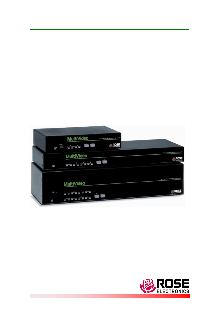
MultiVideo™
KVM SWITCH W ITH MULTIPLE VIDEO
INSTALLATION AND OPERATIONS
SUPPLEMENT
10707 Stancliff Road Houston, Texas 77099
Phone: (281) 933-7673 Internet: WWW.ROSE.COM
Page 2

LIMITED WARRANTY
at his own expense.
Rose Electronics warrants the MultiVideo ™ to be in good working order for one year from the
date of purchase from Rose Electronics or an authorized dealer. Should this product fail to be in
good working order at any time during this one-year warranty period, Rose Electronics will, at its
option, repair or replace the Unit as set forth below. Repair parts and replacement units will be
either reconditioned or new. All replaced parts become the property of Rose Electronics. This
limited warranty does not include service to repair damage to the Unit resulting from accident,
disaster, abuse, or unauthorized modification of the Unit, including static discharge and power
surges.
Limited Warranty service may be obtained by delivering this unit during the one-year warranty
period to Rose Electronics or an authorized repair center providing a proof of purchase date. If
this Unit is delivered by mail, you agree to insure the Unit or assume the risk of loss or damage in
transit, to prepay shipping charges to the warranty service location, and to use the original
shipping container or its equivalent. You must call for a return authorization number first. Under
no circumstances will a unit be accepted without a return authorization number. Contact an
authorized repair center or Rose Electronics for further information.
ALL EXPRESS AND IMPLIED WARRANTIES FOR THIS PRODUCT INCLUDING THE
WARRANTIES OF MERCHANT ABILITY AND FITNESS FOR A PARTICULAR PURPOSE, ARE
LIMITED IN DURATION TO A PERIOD OF ONE YEAR FROM THE DATE OF PURCHASE, AND
NO WARRANTIES, WHETHER EXPRESS OR IMPLIED, WILL APPLY AFTER THIS PERIOD.
SOME STATES DO NOT ALLOW LIMITATIONS ON HOW LONG AN IMPLIED WARRANTY
LASTS, SO THE ABOVE LIMITAT ION MAY NOT APPLY TO YOU.
IF THIS PRODUCT IS NOT IN GOOD WORKING ORDER AS WARRANTIED ABOVE, YOUR
SOLE REMEDY SHALL BE REPLACEMENT OR REPAIR AS PROVIDED ABOVE. IN NO
EVENT WILL ROSE ELECTRONICS BE LIABLE TO YOU FOR ANY DAMAGES INCLUDING
ANY LOST PROFITS, LOST SAVINGS OR OTHER INCIDENTAL OR CONSEQUENTIAL
DAMAGES ARISING OUT OF THE USE OF OR THE INABILITY T O USE SUCH PRODUCT,
EVEN IF ROSE ELECTRONICS OR AN AUTHORIZED DEALER HAS BEEN ADVISED OF THE
POSSIBILITY OF SUCH DAMAGES, OR FOR ANY CLAIM BY ANY OT HER PARTY.
SOME STATES DO NOT ALLOW THE EXCLUSION OR LIMITATION OF INCIDENTAL OR
CONSEQUENTIAL DAMAGES FOR CONSUMER PRODUCTS, SO T HE ABOVE MAY NOT
APPLY TO YOU. THIS WARRANT Y GIVES YOU SPECIFIC LEGAL RIGHTS AND YOU MAY
ALSO HAVE OTHER RIGHT S WHICH MAY VARY FROM STAT E TO STATE.
NOTE: This equipment has been tested and found to comply with the limits for a Class A digital
device, pursuant to Part 15 of the FCC Rules. These limits are designed to provide reasonable
protection against harmful interference when the equipment is operated in a commercial
environment. This equipment generates, uses, and can radiate radio frequency energy and, if
not installed and used in accordance with the instruction manual, m ay cause harmful
interference to radio communications. Operation of this equipment in a residential area is likely
to cause harmful interference in which case the user will be required to correct the interference
IBM ®, AT, and PS/2 are trademarks of International Business Machines Corp.
Microsoft ® and Microsoft Windows™ are registered trademarks of Microsoft Corp.
Apple, Macintosh, and ADB are trademarks of Apple Computer, Inc.
Sun is a registered trademark of Sun MicroSystems Inc.
Any other trademarks mentioned in this manual are acknowledged to be the property of the
trademark owner.
Copyright Rose Electronics 1990-2002. All rights reserved.
No part of this manual may be reproduced, stored in a retrieval system, or
transcribed in any form or any means, electronic or mechanical, including
photocopying and recording, without the prior written permission of Rose Electronics.
Rose Electronics Part # MAN-MV1.3
Printed In the United States of America
Page 3

OVERVIEW
This manual supplement explains the additional information needed to
install and configure the MultiVideo products. Use this supplement in
conjunction with the supplied manual. The supplied manual explains the
additional features and the on-screen display capability of the MultiVideo.
System overview
The MultiVideo is designed to provide seamless, trouble-free switching from
a single KVM station to any connected computer and display the multi-video
output from the computer. You can switch to any of the connected
computers by simple keyboard commands, the front panel – or + buttons, or
from a computer terminal or standalone PC connected to the RS/232 serial
port (not connected to a CPU port). With the OSD option, you can switch to
a connected computer from an on-screen list of the connected computers.
Refer to the UltraView Pro manual for detailed switching instructions.
If your system demands are greater than a single unit can provide, the
MultiVideo can be easily expanded to connect up to 64 computers by
chaining units together with expansion cables. All MultiVideo models can
easily be expanded by chaining the units together and configuring the
system. Using the 2 port “M”-chassis, you can expand the system to 4
computers. The 4 port “B”-chassis can expand to 16 computers, and the 8
port “C”-chassis can expand to 64 computers.
Features
Access up to 64 computers from one KVM station
Optional On-Screen-Display
Available in three different chassis sizes:
M - Chassis - 2 CPUs to 1 Kbd, 1 mouse, and 2 monitors
B - Chassis - 4 CPUs to 1 Kbd, 1 mouse, and 2 monitors
C - Chassis - 2 CPUs to 1 Kbd, 1 mouse, and 4 monitors
4 CPUs to 1 Kbd, 1 mouse, and 4 monitors
8 CPUs to 1 Kbd, 1 mouse, and 2 monitors
VIDEO connection
Video inputs 2-4 are DB25F connectors. A DB25 to HD15 cable is needed
for each video output from a CPU.
MULTIVIDEO INSTALLATION AND OPERATIONS MANUAL
1
Page 4
MODELS
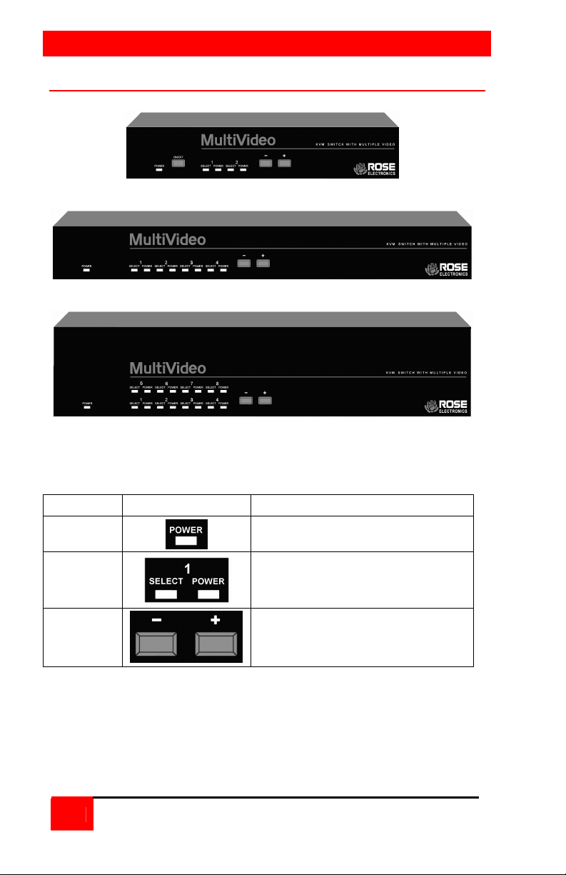
MultiVideo models
M – Chassis
B – Chassis
C - Chassis
Figure 1. MultiVideo models
Label Description
Power
LEDs
- and +
Switches*
Power LED - Green when unit is on
Indicator LEDs; Numbered pairs of
LEDs shows status and power of
connected computers
- Connects to the previous CPU
+ Connects to the next CPU
* The - and + switches are used when:
upgrading the firmware
resetting the unit to factory defaults
running diagnostics.
Table 1. Front panel
2
MULTIVIDEO INSTALLATION AND OPERATIONS MANUAL
Page 5
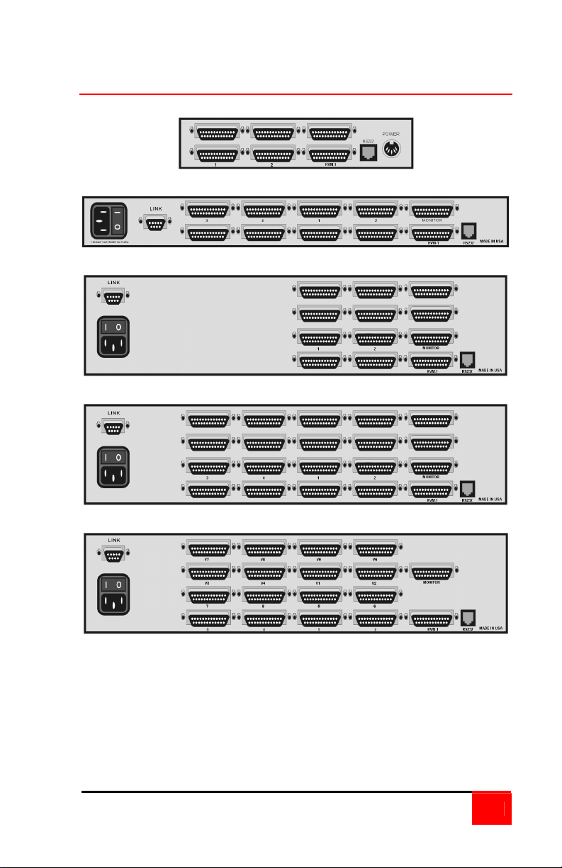
MultiVideo models (rear)
“M” Chassis (2U2V)
“B” Chassis (4U2V)
“C” Chassis (2U4V)
“C” Chassis (4U4V)
“C” Chassis (8U2V)
Figure 2. Rear panel
NOTE: DB9 (LINK) connector on Video expansion units only
Power connector not used on Video expansion unit.
MULTIVIDEO INSTALLATION AND OPERATIONS MANUAL
3
Page 6
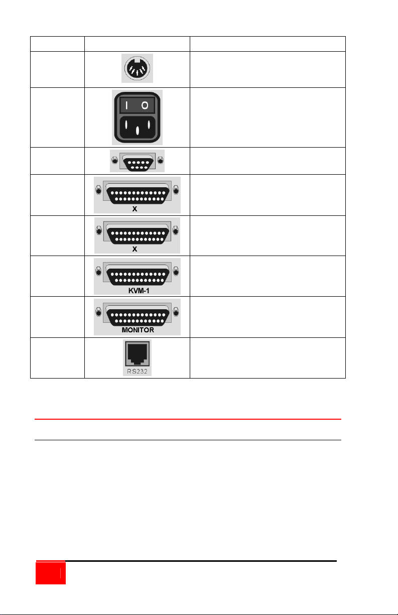
Label Connector Description
Power
None
Link
X =
CPU #
X =
Video #
KVM-1
MONITOR
“M” Chassis only
DIN 5F
Power adapter connector
“B” and “C” Chassis only
IEC320
Power receptacle w/switch
DB9F – Expansion connector
(Video expansion models only)
DB25F – CPU connectors
DB25F – CPU monitor only
connectors
DB25F - KVM connector.
DB25F - KVM additional monitor(s)
RS232
Table 2. Rear panel connectors
RJ12
6-conductor jack
Cables
Master to Slave unit cables
In systems needing additional CPUs, the MultiVideo can be cascaded to
other MultiVideos. To cascade a MultiVideo to other “Slave” units, you will
need one DB25M to DB25M, switch-to-switch cable for each cascaded unit.
The MultiVideo can also be expanded to add additional Video ports. A
DB9M to DB9M, switch-to-switch cable is used with the MultiVideo video
expansion units.
(Rose Electronics switch-to-switch cable part number CAB-CXVSMMnnn.)
(See Appendix B for cable part numbers)
4
MULTIVIDEO INSTALLATION AND OPERATIONS MANUAL
Page 7
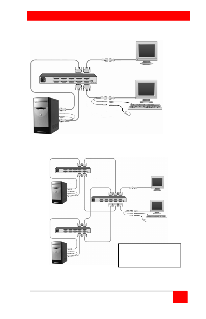
INSTALLATION
Video 1
Video 2
Installation – Single unit
Dual-Video CPUs (1-4)
Figure 3. 4U2V Unit installation
Installation – Cascading units
Slave#2
Dual video
CPUs 5-8
Slave#1
Dual video
CPUs (1-4)
Figure 4. Cascading units
Master
KVM Station
Two additional “Slave”
units can be added to
this configuration.
MULTIVIDEO INSTALLATION AND OPERATIONS MANUAL
5
Page 8
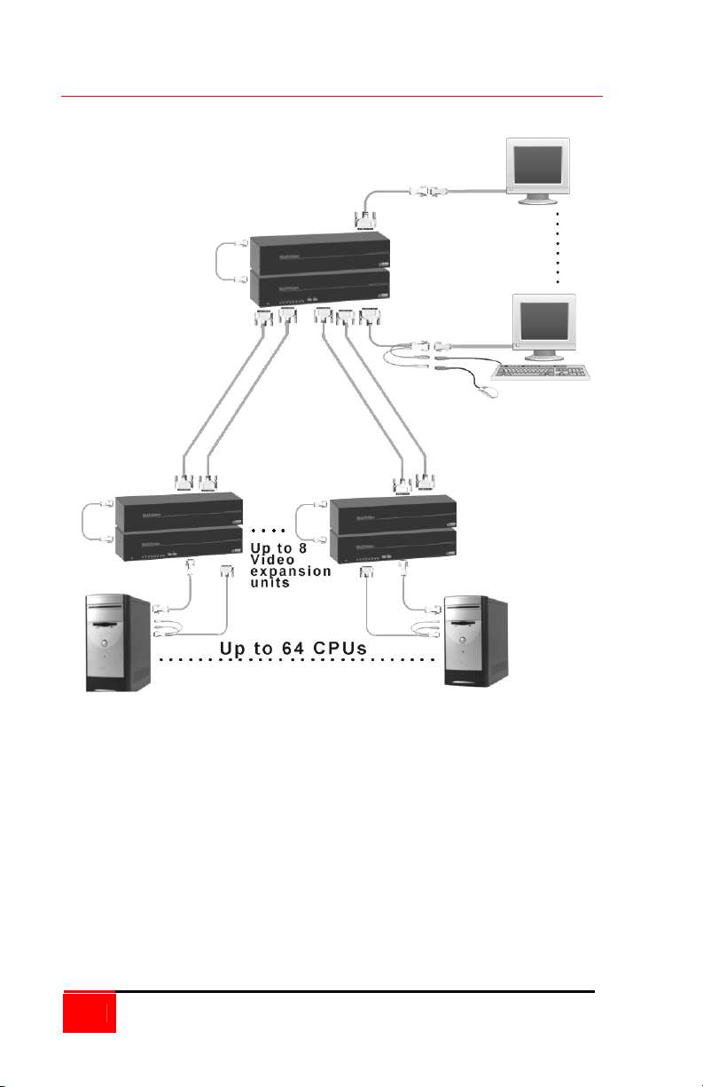
Applications
VIDEO 8
VIDEO 1
6
MULTIVIDEO INSTALLATION AND OPERATIONS MANUAL
Page 9
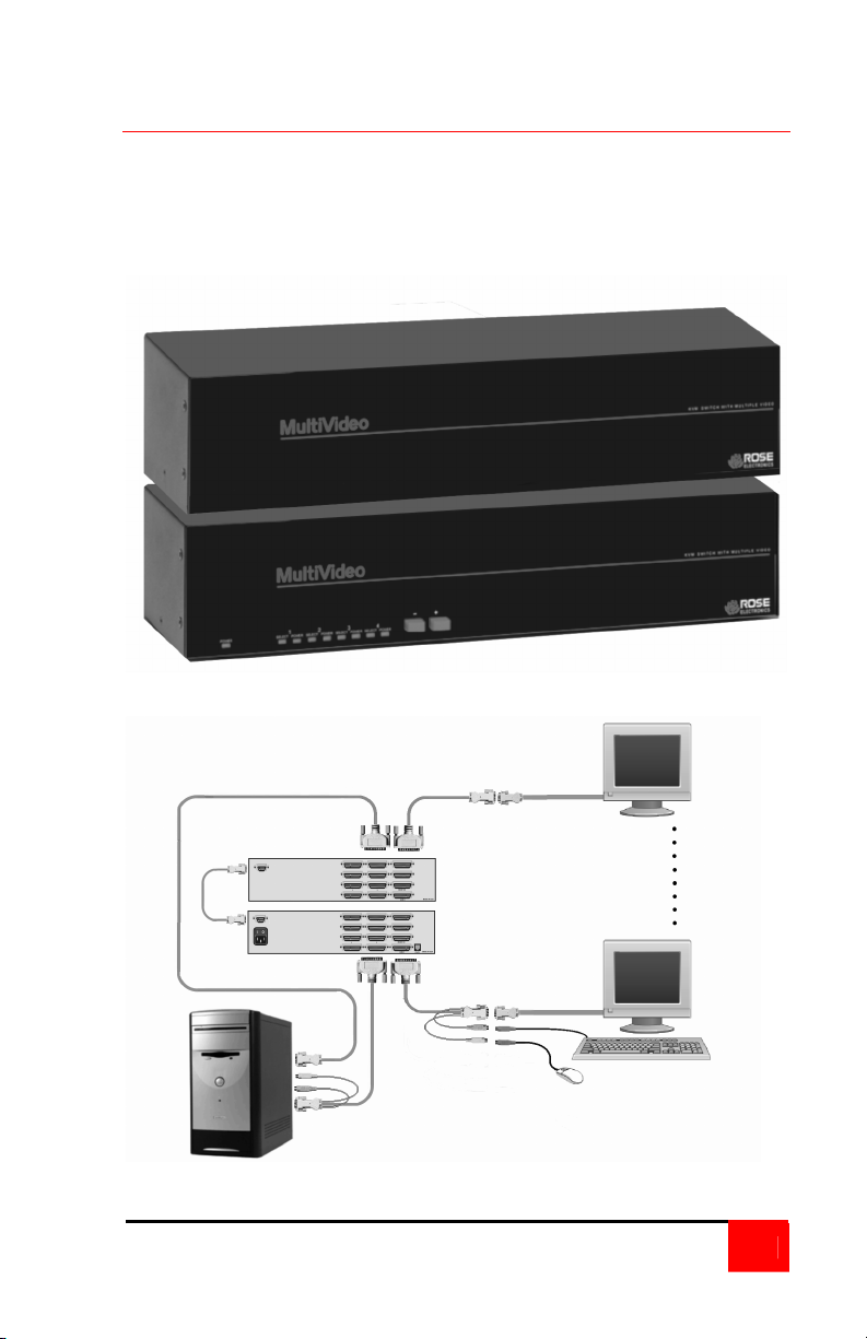
Video 1
Video 8
Installation – Video Expansion system
The MultiVideo can be custom configured to expand the number of video
ports. The example below can have up to 16 separate video sources and
up to 8 video outputs. The KVM station can switch the video by simple
keyboard commands, the push-button switches on the front panel, or from
the on-screen display. Refer to the UltraView Pro manual for detailed
switching instructions.
Figure 5. Custom 2x8 configuration
Link
Cable
16-Video In
8-Video Out
KVM Station
Dual video
CPU 1 of 8
MULTIVIDEO INSTALLATION AND OPERATIONS MANUAL
7
Page 10

APPENDICES
Appendix A. Parts and cables
Part number Description
CAB-D9MM005 DB9M to DB9M Link cable
CAB-CXVSMMnnn DB25M to DB25M Cascading cable
CAB-C1Y0000Cnnn
CAB-C1V0000Mnnn
CAB-S13W3000Cnnn
CAB-SC0000Cnnn
CAB-SB0000Mnnn
CAB-S13W30000Mnnn
Appendix B. General Specifications
The MultiVideo part number is Mwx-yUzV
Where w = platform, E = (Multi-platform) PC, SUN, Apple, Unix
P = (PC) PC and Unix computers
Where x = chassis size, M (mini), B (low), C (high)
Where y = number of CPUs (2, 4, or 8)
Where z = number of monitors (2 or 4)
The MultiVideo Video expansion model part numbers are:
MPC – 2U4V/MV (Master unit)
MPC – 2U4V/SL (Slave unit)
Connectors Power – IEC 320 standard receptacle
Indicators 1 Power LED
HD15M to DB25F Video only cable (CPU)
HD15F to DB25F Video only cable (Monitor)
CPU (SGI) 13W3 to DB25M video only cable
CPU (SUN) 13W3 to DB25M video only cable
SUN video 13W3 to DB25M video only cable
SGI video 13W3 to DB25M video only cable
(MPC-2U4V/MV model only)
CPU/KVM connector – DB25F
Video ports – DB25F
RS232 connector – RJ12, 6 conductor
Interconnect – DB9 (Custom configuration)
2-8 Select LEDs
2-8 Computer power LEDs
8
MULTIVIDEO INSTALLATION AND OPERATIONS MANUAL
Page 11
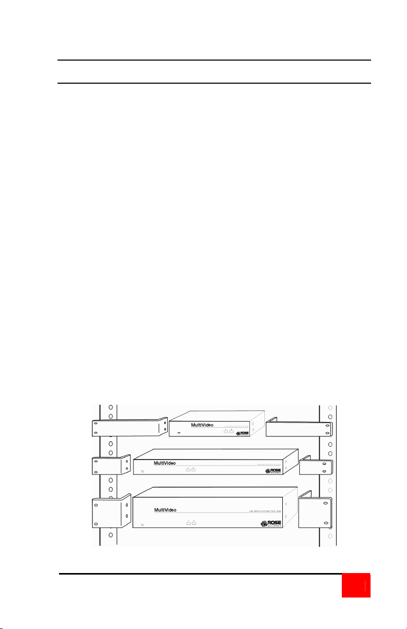
Appendix C. Rack mount
Rack Mount Instructions
The optional rack mount kit includes the following items:
• Two black anodized mounting brackets.
• Four 6 x 32 x 3/8” flat head mounting screws.
• Mounting instructions insert.
To rack mount your MultiVideo, attach the two rack mounting brackets to
your unit with the short flange against the unit using the four screws
provided. Secure the mounting brackets to the rack using the appropriate
size bolts, nuts and lock washers. Using hardware other than that provided
could cause damage to the electronics and/or result in loss of mounting
integrity. Do not over tighten the screws used to mount the unit to the
mounting brackets.
The following general guidelines should be observed when installing your
unit into a rack.
a). The MultiVideo is designed to work in an ambient temperature of
ο
C to 45
0
ο
C (32
ο
F – 113ο F).
b). Do not block power supply vents or otherwise restrict airflow when
rack-mounting this unit.
c). Mechanical loading of the rack should be considered to prevent
instability and possible tipping over.
d). Tighten all connectors securely and provide adequate strain relief
for all cables.
e). Provide a grounded power source to all units. Pay special
attention to overall branch circuit load ratings before connecting
equipment to this source. Overloaded circuits are potential fire
hazards and can cause equipment failures or poor performance.
MULTIVIDEO INSTALLATION AND OPERATIONS MANUAL
9
Page 12

10707 Stancliff Road Houston, Texas 77099
Phone: (281) 933-7673 Internet: WWW.ROSE.COM
 Loading...