

Page 1
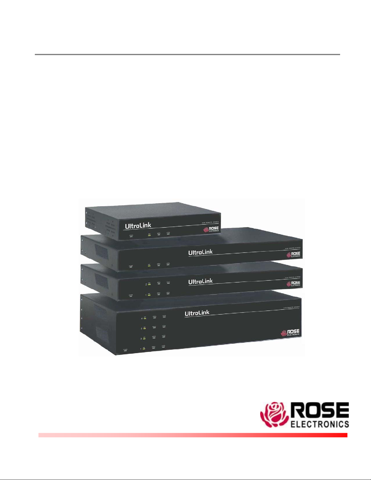
UltraLink
INSTALLATION AND OPERATIONS
MANUAL
KVM REMOTE ACCESS
10707 Stancliff Road Phone (281) 933-7673
Houston, Texas 77099 Internet: WWW.ROSE.COM
Page 2
LIMITED WARRANTY
Rose Electronics
Rose Electronics or an authorized dealer. Should this product fail to be in good working order at any time during this
one-year warranty period, Rose Electronics will, at its option, repair or replace the Unit as set forth below. Repair
parts and replacement units will be either reconditioned or new. All replaced parts become the property of Rose
Electronics. This limited warranty does not include service to repair damage to the Unit resulting from accident,
disaster, abuse, or unauthorized modification of the Unit, including static discharge and power surges.
Limited Warranty service may be obtained by delivering this unit during the one-year warranty period to Rose
Electronics or an authorized repair center providing a proof of purchase date. If this Unit is delivered by mail, you
agree to insure the Unit or assume the risk of loss or damage in transit, to prepay shipping charges to the warranty
service location, and to use the original shipping container or its equivalent. You must call for a return authorization
number first. Under no circumstances will a unit be accepted without a return authorization number. Contact an
authorized repair center or Rose Electronics for further information.
ALL EXPRESS AND IMPLIED WARRANTIES FOR THIS PRODUCT INCLUDING THE WARRANTIES OF
MERCHANTABILITY AND FITNESS FOR A PARTICULAR PURPOSE, ARE LIMITED IN DURATION TO A PERIOD
OF ONE YEAR FROM THE DATE OF PURCHASE, AND NO WARRANTIES, WHETHER EXPRESS OR IMPLIED,
WILL APPLY AFTER THIS PERIOD. SOME STATES DO NOT ALLOW LIMITATIONS ON HOW LONG AN IMPLIED
WARRANTY LASTS, SO THE ABOVE LIMITATION MAY NOT APPLY TO YOU.
IF THIS PRODUCT IS NOT IN GOOD WORKING ORDER AS WARRANTED ABOVE, YOUR SOLE REMEDY
SHALL BE REPLACEMENT OR REPAIR AS PROVIDED ABOVE. IN NO EVENT WILL ROSE ELECTRONICS BE
LIABLE TO YOU FOR ANY DAMAGES INCLUDING ANY LOST PROFITS, LOST SAVINGS OR OTHER
INCIDENTAL OR CONSEQUENTIAL DAMAGES ARISING OUT OF THE USE OF OR THE INABILITY TO USE
SUCH PRODUCT, EVEN IF ROSE ELECTRONICS OR AN AUTHORIZED DEALER HAS BEEN ADVISED OF THE
POSSIBILITY OF SUCH DAMAGES, OR FOR ANY CLAIM BY ANY OTHER PARTY.
SOME STATES DO NOT ALLOW THE EXCLUSION OR LIMITATION OF INCIDENTAL OR CONSEQUENTIAL
DAMAGES FOR CONSUMER PRODUCTS, SO THE ABOVE MAY NOT APPLY TO YOU. THIS WARRANTY
GIVES YOU SPECIFIC LEGAL RIGHTS AND YOU MAY ALSO HAVE OTHER RIGHTS WHICH MAY VARY FROM
STATE TO STATE
NOTE: This equipment has been tested and found to comply with the
limits for a Class B digital device, pursuant to Part 15 of the FCC Rules.
These limits are designed to provide reasonable protection against
harmful interference when the equipment is operated in a commercial
environment. This equipment generates, uses, and can radiate radio
IBM ®, AT, and PS/2 are trademarks of International Business Machines Corp.
Microsoft ® and Microsoft Windows™ are registered trademarks of Microsoft Corp.
Apple, Macintosh, and ADB are trademarks of Apple Computer, Inc.
Sun is a registered trademark of Sun MicroSystems Inc.
Any other trademarks mentioned in this manual are acknowledged to be the property of the trademark owner.
®
warrants the UltraLink™ to be in good working order for one year from the date of purchase from
Copyright Rose Electronics 1990 – 2003. All rights reserved.
No part of this manual may be reproduced, stored in a retrieval system, or transcribed in any form or any
means, electronic or mechanical, including photocopying and recording, without the prior written
permission of Rose Electronics
.
Rose Electronics Part # MAN-UL2.0
Printed in the United States of America Revision 2.0
Page 3
FEDERAL COMMUNICATIONS COMMISSION AND INDUSTRY
CANADA
RADIO-FREQUENCY INTERFERENCE STATEMENTS
This equipment generates, uses, and can radiate radio frequency energy and if not
installed and used properly, that is, in strict accordance with the manufacturer’s
instructions, may cause interference to radio communication. It has been tested and
found to comply with the limits for a Class B digital device in accordance with the
specifications of Part 15 of FCC rules, which are designed to provide reasonable
protection against such interference when the equipment is operated in a commercial
environment. Operation of this equipment in a residential area is likely to cause
interference, in which case the user at his own expense will be required to take
whatever measures may be necessary to correct the interference.
Changes or modifications not expressly approved by the party responsible for
compliance could void the user’s authority to operate the equipment. This digital
apparatus does not exceed the Class B limits for radio noise regulation of industry
Canada.
Le présent appareil numérique n’émet pas de bruits radioélectriques dépassant les
limites applicables aux appareils numériques de la classe B prescrites dans le
Règlement sur le brouillage radioélectrique publié par Industrie Canada.
EUROPEAN UNION DECLARATION OF CONFORMITY
ACCORDING TO COUNCIL DIRECTIVE 89/336EEC
This equipment is in conformity with the requirements
of the European EMC directive
89/336/EEC in respect of:
EN55022: (Class B)
EN50082-1 / EN60555-2, and
The Low Voltage Directive.
Page 4

UltraLink Quick Start Guide
All Models
The following 12 pages are Quick Start Guides for all UltraLink models
Pages A, B, C – Model UL-V3
Pages D, E, F – Model UL-LV3
Pages G, H, I – Model UL-DV3
Pages J, K, L – model UL-QV3
Refer to the appropriate pages for your model
Page 5
Introduction
The installation assumes the following:
You have an active Ethernet TCP/IP network.
You are connecting the UltraLink to a standalone
computer or KVM switch.
You have a PC on the network where you will
install the Viewer software.
Connections
UltraLink configuration
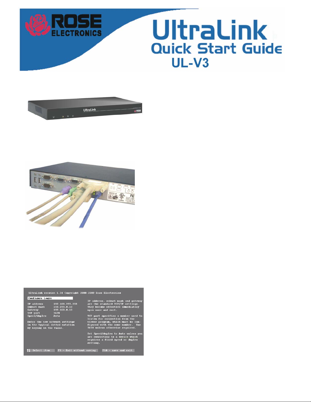
Connect the cables to the UltraLink.
Connect your keyboard, monitor, and mouse to the
connectors on the bottom row as shown.
Connect the network cable (not provided) to your
10MB or 100MB Ethernet network port.
Connect the DB25 connector to a KVM switch or to
a standalone computer with one or the other
provided cables.
Use the DB25 to DB25 cable to connect to
the KVM port of a Rose KVM switch.
Use the DB25 to HD15-PS2-PS2 cable to
connect to a standalone computer or another
the local KVM port, please refer to the UltraLink
manual for instructions on how to connect it.
KVM switch.
Note: These instructions do not apply to installation of
Configure the UltraLink IP address
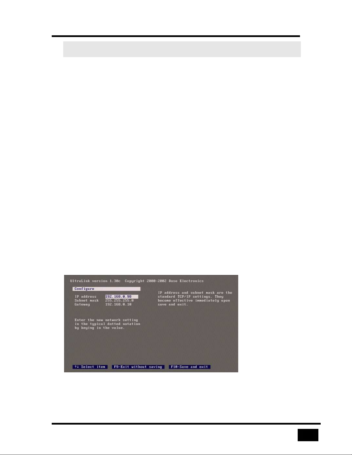
Power on the UltraLink and you will see its
start-up splash screen. Wait for the green screen.
Hit F10 to go to the UltraLink configuration. The
screen changes color from green to gray.
Hit F1 if you want to read some help.
Enter a user ID of “admin” with no password.
Enter the IP address, subnet mask, optional
gateway address, TCP port, and Speed/duplex.
Hit F10 to save the network information.
The UltraLink is now active at this address.
A
Page 6
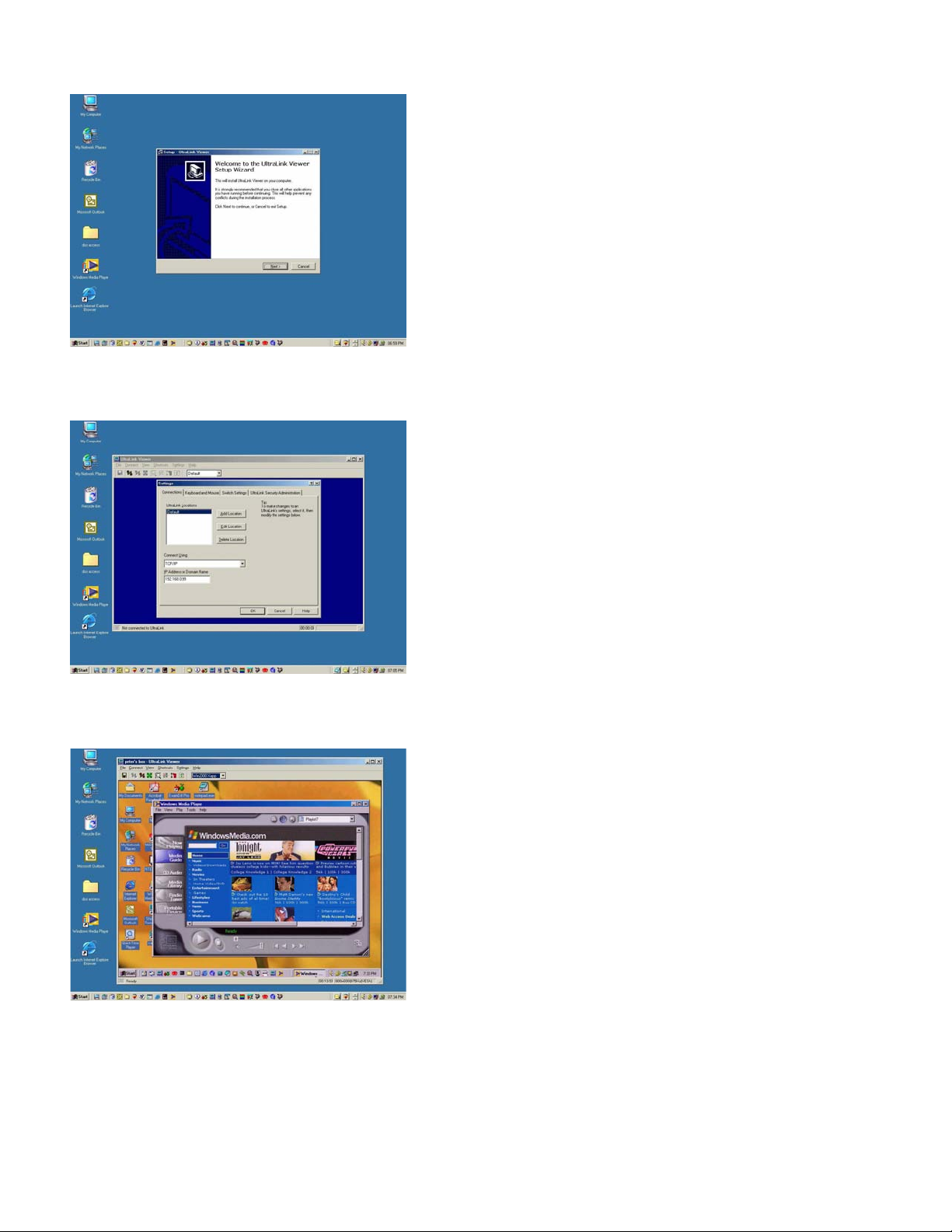
Viewer installation
Viewer configuration
Install the Viewer on a PC on your network.
Two installation diskettes are provided.
Insert the setup diskette and run setup.
You will be guided through a standard Windows-style
installation process.
Click through to specify the installation directory and
if you want the associated start menu folder,
desktop, and quick launch icons.
Read the readme file for late breaking developments.
Configure the Viewer’s IP address.
Run the UltraLink Viewer program.
Go to the Settings-Connections tab and use Edit
Location to modify Default to a name of your
choosing.
Viewer operation
Change the IP address to the one previously
given to the UltraLink.
Once you click OK, the new location name
appears on the UltraLink tool bar.
Click help if you want to know more about the Viewer
or proceed below to make a connection.
Make a connection.
Hit the connect icon (second from the left) or click on
Connect. A logon box should appear.
Enter the user ID of “admin” and no password.
After a moment, you should see the video attached
to the UltraLink.
The pass-through message box appears. Click OK
to forward your local keyboard and mouse to the
remote computer.
Hit Ctrl-Alt-P to exit the Viewer from pass-
through mode or move the mouse rapidly.
B
UltraLink Quick Start Guide version 1.2 Copyright Rose Electronics 2002
Don’t forget to go to the Settings-Security tab to
change the user ID and password for its unsecured
default value.
Refer to the manual or Viewer help for further
exploration.
Page 7
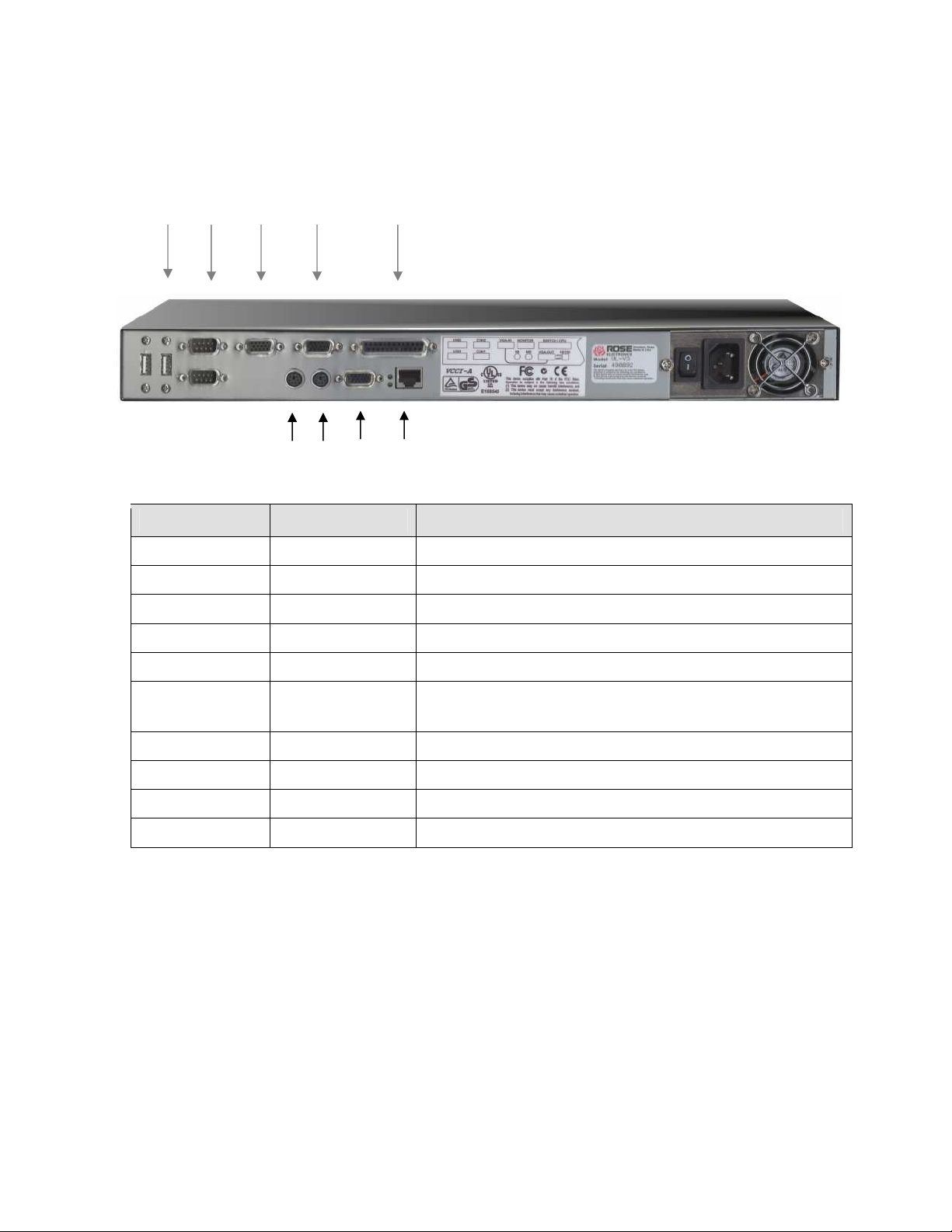
UltraLink UL-V3
A B C D E
F G H I
Connector Label Type/Usage
POWER IEC320 / 115-230 VAC, 50-60Hz, Auto-switching
A USB Type A / USB keyboard / mouse
B Serial (2) DB9 (Reserved)
C VGA-In Video loopback
D Monitor HD15M / KVM monitor
E
F Keyboard MiniDin6 / KVM keyboard
G Mouse MiniDin6 / KVM mouse
H VGA-Out Video loopback
I NETWORK RJ45 / Network connection (10MB / 100MB)
SWITCH/CPU DB25F / KVM switch or standalone computer
connection
POWER
C
Page 8
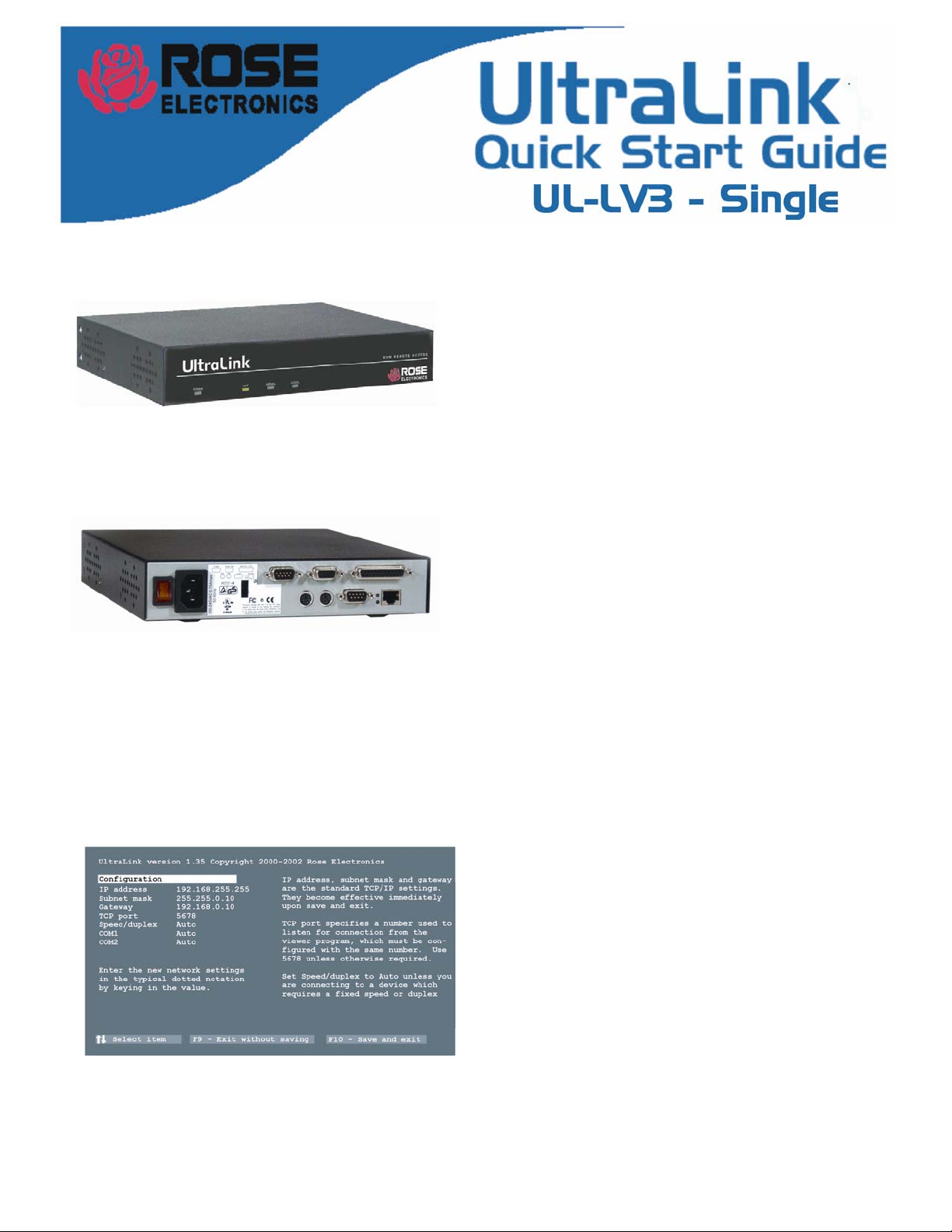
Introduction
Connections
UltraLink configuration
The installation assumes the following:
You have an active Ethernet TCP/IP network.
You are connecting the UltraLink to a standalone
computer or KVM switch.
You have a PC on the network where you will install
the Viewer software.
Connect the cables to the UltraLink.
Connect your keyboard, monitor, and mouse to the
corresponding UltraLink rear connectors.
Connect the network cable (not provided) to your
10MB or 100MB Ethernet network port.
Connect the DB25 connector to a KVM switch or to
a standalone computer with one of the provided
cables. Use the DB25 to DB25 cable to connect to
the KVM port of a Rose KVM switch. Use the DB25
to HD15-PS2-PS2 cable to connect to a standalone
computer or another KVM switch.
Note: These instructions do not apply to installation of
the local KVM port, please refer to the UltraLink
manual for instructions on how to connect it.
Configure the UltraLink IP address
Power on the UltraLink and you will see its
start-up splash screen. Wait for the green screen.
D
UltraLink Quick Start Guide version 1.2 Copyright Rose Electronics 2002
Hit F10 to go to the UltraLink configuration. The
screen changes color from green to gray.
Enter a user ID of “admin” with no password.
Enter the IP address, subnet mask, optional
gateway address, TCP port, and Speed/duplex.
Hit F10 to save the network information.
The UltraLink is now active at this address
Hit F1 if you want to read some help.
.
Page 9
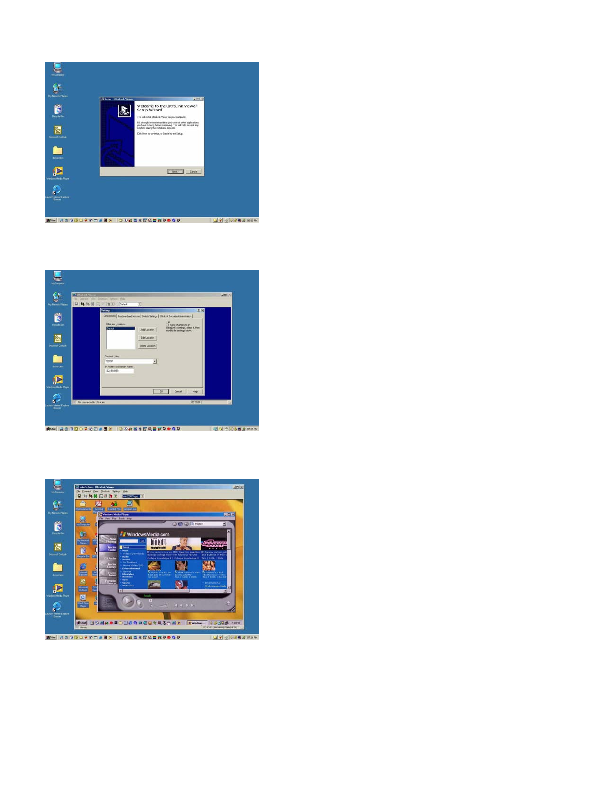
Viewer installation
Viewer configuration
Install the Viewer on a PC on your network.
Two installation diskettes are provided.
Insert the setup diskette and run setup.
You will be guided through a standard Windows-style
installation process.
Click through to specify the installation directory and
if you want the associated start menu folder,
desktop, and quick launch icons.
Read the readme file for late breaking developments.
Configure the Viewer’s IP address.
Run the UltraLink Viewer program.
Go to the Settings-Connections tab and use Edit
Location to modify Default to a name of your
choosing.
Viewer operation
Change the IP address to the one previously
assigned to the UltraLink.
Once you click OK, the new location name
appears on the UltraLink tool bar.
Click help if you want to know more about the Viewer
or proceed below to make a connection.
Make a connection.
Hit the connect icon (second from the left) or click on
Connect. A logon box will appear.
Enter the user ID of “admin” and no password.
After a moment, you should see the video attached
to the UltraLink.
The pass-through message box appears. Click OK
to forward you local keyboard and mouse to the
remote computer.
Hit Ctrl-Alt-P to exit the Viewer from the pass-
through mode or move the mouse rapidly.
Don’t forget to go to the Settings-Security tab to
Refer to the manual or Viewer help for further
UltraLink UL-LV3 Quick Start Guide version 1.2 Copyright Rose Electronics 2002
change the user ID and password from its unsecured
default value.
exploration.
E
Page 10
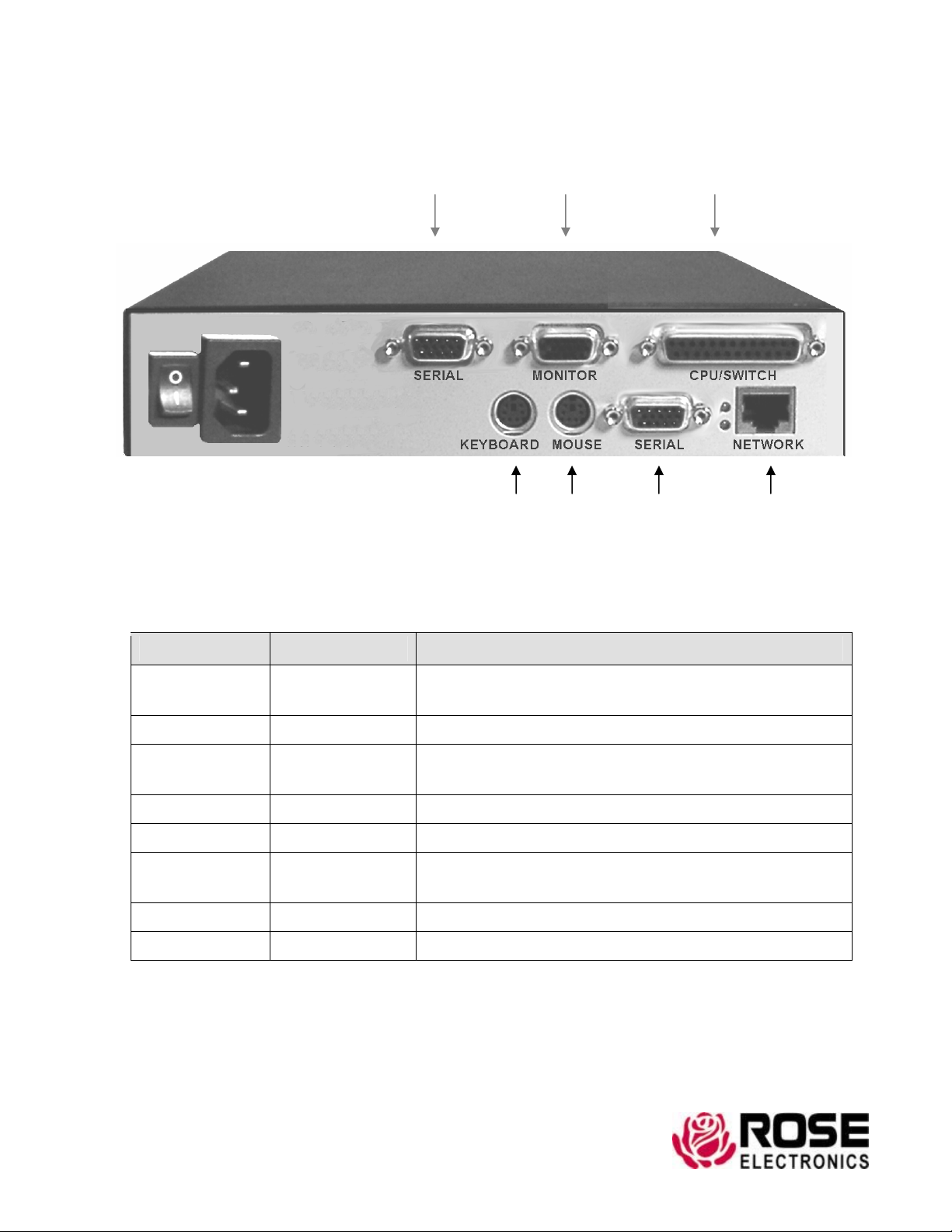
UltraLink UL-LV3
G
A B C
POWER
D E F
Connector Label Type/Usage
A SERIAL
B MONITOR HD15F / Local monitor connection
C SWITCH/CPU
D KEYBOARD PS/2 / Local keyboard connection
E MOUSE PS/2 / Local mouse connection
F SERIAL
DB9M/ Serial ports for modem or serial device
(Reserved for future use)
DB25F / KVM switch or standalone computer
connection
DB9M/ Serial ports for modem or serial device
(Reserved for future use)
G NETWORK RJ45 / Network connection (10MB / 100MB)
POWER IEC320 / 115-230 VAC, 50-60Hz, Auto-switching
F
Rose Electronics 10707 Stancliff Road, Houston, Texas 77099 USA
281-933-7673 800-333-9343 (USA) +44 (0) 1264 850574 (Europe) +65 6324 2322(Far East)
W W W . R O S E . CO M
Page 11
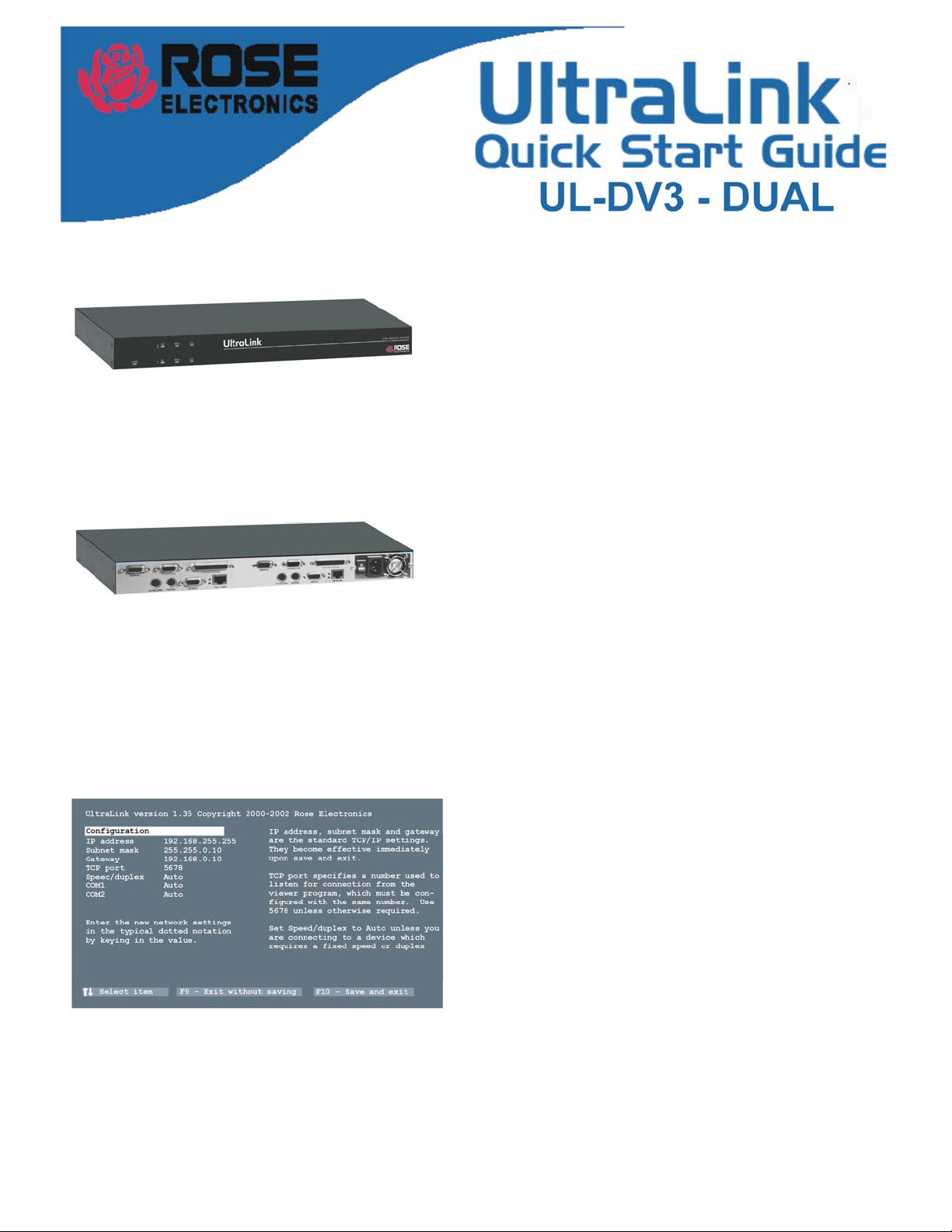
Introduction
Connections
UltraLink configuration
The installation assumes the following:
The Dual UltraLink consists of two independent
modules. Each one must be set-up and configured.
You have an active Ethernet TCP/IP network.
You are connecting the UltraLink to two standalone
computers or a KVM switch.
You have a PC on the network where you will
install the Viewer software.
Connect the cables to the UltraLink.
Connect a keyboard, monitor, and mouse to the
appropriate connectors on one or both modules..
Connect two network cables (not provided) to a
10MB or 100MB Ethernet network port or hub.
Connect two DB25 connector to a KVM switch or
two standalone computers with one of the provided
cables. Use the DB25 to DB25 cable to connect to
the KVM port of a Rose KVM switch. Use the
DB25 to HD15-PS2-PS2 cable to connect to a
standalone computer or another KVM switch.
Note: These instructions do not apply to installation of
the local KVM port. Please refer to the UltraLink
manual for instructions on how to connect it.
Configure the UltraLink IP addresses
Power on the UltraLink and you will see its
start-up splash screen. Wait for the green screen.
Hit F10 to go to the UltraLink configuration. The
screen changes color from green to gray.
Hit F1 if you want to read some help.
Enter a user ID of “admin” with no password.
Enter the IP address, subnet mask, optional
gateway address, TCP port, and Speed/duplex.
Hit F10 to save the network information.
The UltraLink is now active at this address.
Repeat the above set-up for the other module. .
G
Page 12
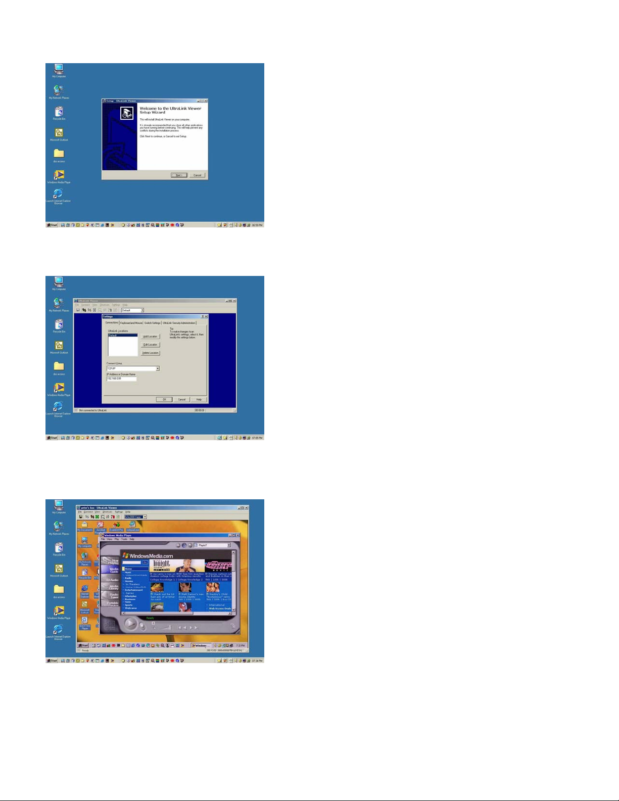
Viewer installation
Viewer configuration
Install the Viewer on a PC on your network.
Two installation diskettes are provided.
Insert the setup diskette and run setup.
You will be guided through a standard Windows-style
installation process.
Click through to specify the installation directory and
if you want the associated start menu folder,
desktop, and quick launch icons.
Read the readme file for late breaking developments.
Configure the Viewer’s IP addresses.
Run the UltraLink Viewer program.
Go to the Settings-Connections tab and use Edit
Location to modify Default to a name of you
choosing.
Viewer operation
Change the IP address to one that was assigned to
one of the two UltraLinks. Click OK. This sets up the
first UltraLink.
Click on “Add Location” and add the second
UltraLink to the Viewer. Enter its correct IP address.
This sets up the second UltraLink. Once you click
OK, the new location name appears on the UltraLink
tool bar.
Click help if you want to know more about the Viewer
or proceed below to make a connection.
Make a connection.
Hit the connect icon (second from the left) or click on
Connect. A logon box should appear.
Enter the user ID of “admin” and no password.
After a moment, you should see the video attached
to the UltraLink.
The pass-through message box appears. Click OK
to forward you local keyboard and mouse to the
remote computer.
Hit Ctrl-Alt-P to exit the Viewer from pass-
through mode or move the mouse rapidly.
Don’t forget to go to the Settings-Security tab to
change the user ID and password for its unsecured
default value.
Refer to the manual or Viewer help for further
exploration.
H
Page 13
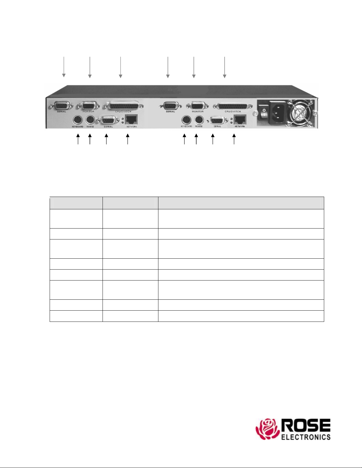
UltraLink UL-DV3
A B C A B C
MODULE
#1
D E F G
D E F G POWER
Connector Label Type/Usage
A
B MONITOR HD15F / Local monitor connection
C
D KEYBOARD PS/2 / Local keyboard connection
SERIAL DB9M/ Serial ports for modem or serial device
(Reserved for future use)
SWITCH/CPU DB25F / KVM switch or standalone computer
connection
MODULE
#2
E MOUSE PS/2 / Local mouse connection
F
G NETWORK RJ45 / Network connection (10MB / 100MB)
POWER IEC320 / 115-230 VAC, 50-60Hz, Auto-switching
SERIAL DB9M/ Serial ports for modem or serial device
(Reserved for future use)
I
281-933-7673 800-333-9343 (USA) +44 (0) 1264 850574 (Europe) +65 6324 2322(Far East)
Rose Electronics 10707 Stancliff Road, Houston, Texas 77099 USA
W W W . R O S E . CO M
Page 14
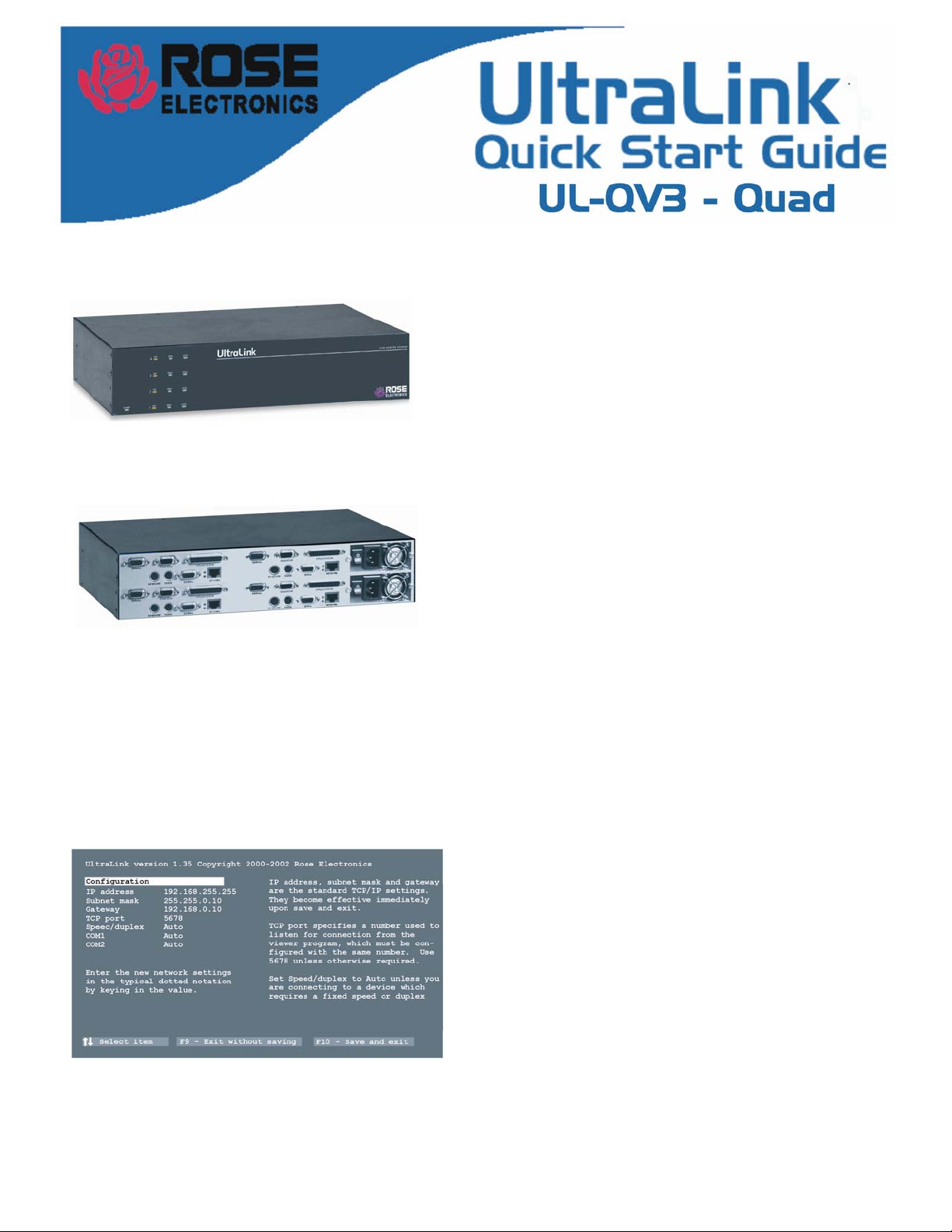
Introduction
The installation assumes the following:
You have an active Ethernet TCP/IP network.
You are connecting the UltraLink to four standalone
computers or a KVM switch.
You have a PC on the network where you will install
the Viewer software.
Connections
UltraLink configuration
Connect the cables to the UltraLink.
The Quad UltraLink consists of four independent
modules. Each one must be setup and configured.
Connect a keyboard, monitor, and mouse to the
appropriate connectors on one of the modules.
Connect a network cable (not provided) to your 10MB
or 100MB Ethernet network port.
(Note: The four network outputs can be connected
to a hub)
Connect the DB25 connectors to a KVM switch or to
four standalone computers with one of the provided
cables. Use the DB25 to DB25 cable to connect to
the KVM ports of a Rose KVM switch. Use the Db25
to HD15-PS/2-PS/2 cable to connect to a standalone
computer or another KVM switch.
Note: These instructions apply for each of the 4 modules
Configure the UltraLink IP address
Power on the UltraLink and you will see its
start-up splash screen. Wait for the green screen.
Hit F10 to go to the UltraLink configuration. The
screen changes color from green to gray.
Hit F1 if you want to read some help.
Enter a user ID of “admin” with no password.
Enter the IP address, subnet mask, optional gateway
address, TCP port, and Speed/duplex for this
UltraLink.
Hit F10 to save the network information.
J
This UltraLink is now active at this address.
Repeat the above procedure for each of the four
UltraLink modules.
Page 15
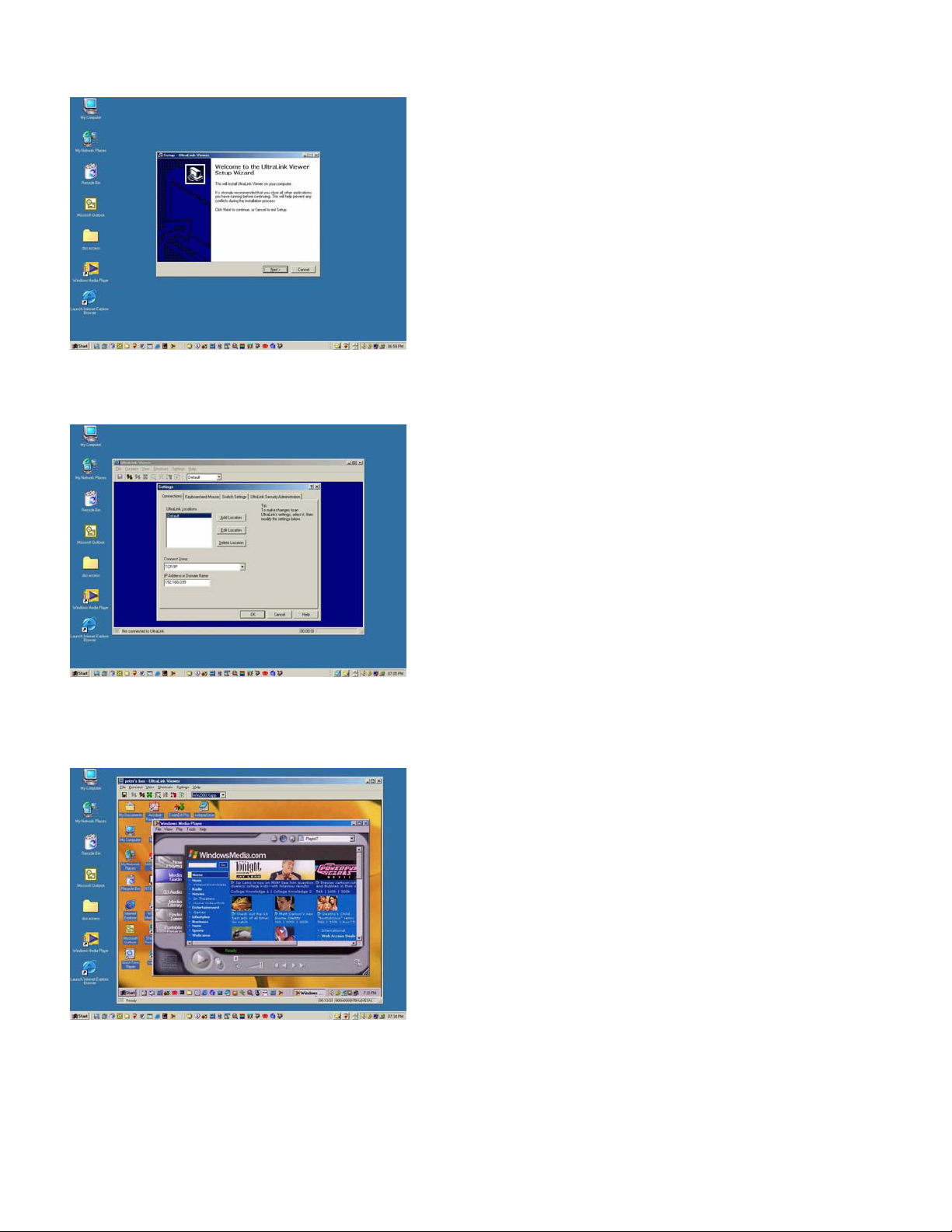
Viewer installation
Viewer configuration
Install the Viewer on a CP on your network.
Two installation diskettes are provided.
Insert the setup diskette and run setup.
You will be guided through a standard Windows-style
installation process.
Click through to specify the installation directory and
if you want the associated start menu folder,
desktop, and quick launch icons.
Read the readme file for late breaking developments.
Configure the Viewer’s IP address.
Run the UltraLink Viewer program.
Go to the Settings-Connections tab and use Edit
Location to modify Default to a name of you
choosing.
Viewer operation
Change the IP address to one that was assigned to
one of the four UltraLink modules, Click OK. This
sets up the first UltraLink.
Click on “Add Location” and add the other three
UltraLink modules to the Viewer. Enter its correct IP
address. This sets up the next UltraLink module.
Once you click OK, the new location name appears
on the UltraLink tool bar.
Repeat the “Add Location” function for the other
UltraLink modules.
Make a connection.
Hit the connect icon (second from the left) or click on
Connect. A logon box should appear.
Enter the user ID of “admin” and no password.
After a moment, you should see the video attached
to the UltraLink.
The pass-through message box appears. Click OK
to forward you local keyboard and mouse to the
remote computer.
Hit Ctrl-Alt-P to exit the Viewer from pass-
through mode or move the mouse rapidly.
Don’t forget to go to the Settings-Security tab to
change the user ID and password for its unsecured
default value.
Refer to the manual or Viewer help for further
exploration.
K
Page 16
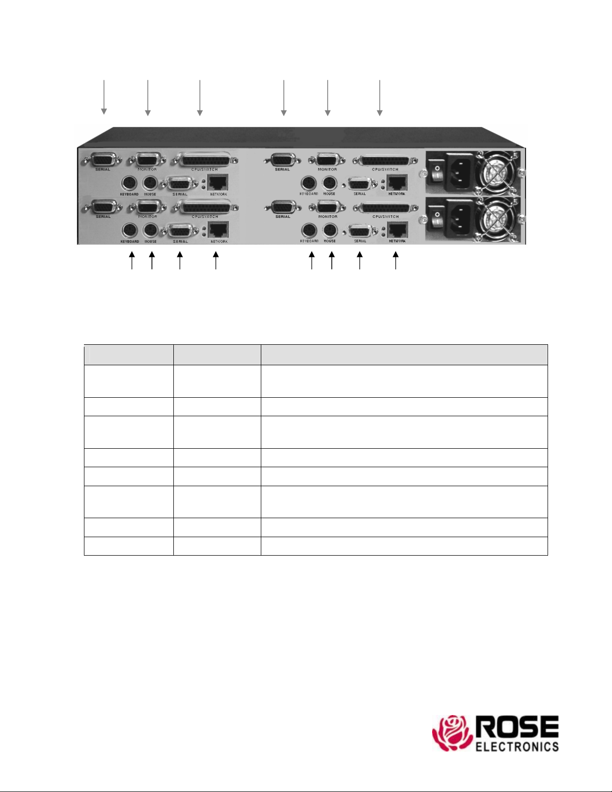
UltraLink UL-QV3
A B C A B C
MODULE
#3
MODULE
#1
D E F G
D E F G POWER
Connector Label Type/Usage
A
B MONITOR HD15F / Local monitor connection
C
SERIAL DB9M/ Serial ports for modem or serial device
(Reserved for future use)
SWITCH/CPU
DB25F / KVM switch or standalone computer
connection
MODULE
#4
MODULE
#2
D KEYBOARD PS/2 / Local keyboard connection
E MOUSE PS/2 / Local mouse connection
F
SERIAL DB9M/ Serial ports for modem or serial device
(Reserved for future use)
G NETWORK RJ45 / Network connection (10MB / 100MB)
POWER IEC320 / 115-230 VAC, 50-60Hz, Auto-switching
L
281-933-7673 800-333-9343 (USA) +44 (0) 1264 850574 (Europe) +65 6324 2322(Far East)
Rose Electronics 10707 Stancliff Road, Houston, Texas 77099 USA
W W W . R O S E . CO M
Page 17

Table of Contents
I
NTRODUCTION
................................................................................................................ 1
Front Panel .................................................................................................................. 5
Back Panel .................................................................................................................. 5
ETTING STARTED
G
........................................................................................................... 6
In the Box.................................................................................................................... 6
You Will Need ............................................................................................................ 6
ONNECTIONS
C
.................................................................................................................. 7
There are two ways to connect the UltraLink ............................................................. 7
S
TART UP
......................................................................................................................... 8
Power On .................................................................................................................... 8
About Logins .............................................................................................................. 9
Using Configure Login for the First Time ................................................................ 10
Using Connect Login for the First Time................................................................... 10
The Configure Screen ............................................................................................... 11
Connect Contention .................................................................................................. 12
Password Defeat........................................................................................................ 12
NSTALLING THE ULTRALINK VIEWER
I
........................................................................... 13
Requirements ............................................................................................................ 13
The Setup Wizard ..................................................................................................... 13
Using the Viewer for the First Time ......................................................................... 14
T
HE VIEWER SCREEN
..................................................................................................... 15
The Title Bar ............................................................................................................. 15
Menu Commands ...................................................................................................... 15
The Toolbar............................................................................................................... 15
The Display Area ...................................................................................................... 16
The Status Bar........................................................................................................... 17
Windows Buttons...................................................................................................... 17
Question Mark Help.................................................................................................. 18
ENU COMMANDS
M
........................................................................................................ 19
File ............................................................................................................................ 19
Connect ..................................................................................................................... 20
View.......................................................................................................................... 20
Shortcuts ................................................................................................................... 23
Settings...................................................................................................................... 24
Help........................................................................................................................... 26
C
ONFIGURATION SETTINGS
............................................................................................ 27
Connections............................................................................................................... 28
Keyboard and Mouse ................................................................................................ 30
KVM Switch ............................................................................................................. 33
Security ..................................................................................................................... 35
ONNECTING AND LOGGING IN
C
...................................................................................... 39
Connecting ................................................................................................................ 39
Login ......................................................................................................................... 39
Pass-through Mode ................................................................................................... 40
Disconnecting ........................................................................................................... 42
Page 18

V
IEW MODES
................................................................................................................. 43
Scaled / Scrolled ....................................................................................................... 43
Auto Size................................................................................................................... 44
Full Screen / Windowed............................................................................................ 45
Color Modes.............................................................................................................. 46
SING A
U
KVM S
WITCH
.................................................................................................. 47
KVM Switch Features............................................................................................... 47
Remote Computer Select .......................................................................................... 47
Quad Screen .............................................................................................................. 48
Switch File Import and Export.................................................................................. 49
AFETY
S
A
PPENDIX A. RACK MOUNT
............................................................................................................................ 3
........................................................................................... 52
Rack mount illustration............................................................................................. 52
NDEX
I
............................................................................................................................ 53
Page 19
Introduction
1
Introduction
KVM Remote Access
Access your servers anywhere in the world from the UltraLink Viewer program
Features and Benefits
UltraLink is a powerful product that extends the range of access to your computers to
anywhere in the world. Its advanced design makes it compatible with industry standard
KVM switches and computers. It is most commonly used to extend a KVM switch’s user
port to be accessed by either a LAN, WAN, or dial-up connection.
Connect the unit to a standalone computer or KVM switch and your Ethernet network.
Assign an IP address to the UltraLink and run the remote access client from any
workstation.
You can access the server just like you were standing in front of it, but you can be at home,
work, or half way around the world. Easy to configure security features, prevent
unauthorized access.
The UltraLink has a sophisticated scaling feature allowing you to position any size image of
your server anywhere on your screen. Now you can monitor servers while you work on
other tasks. It is also ideal for fast updates over slow links because less data is sent.
Because the unit is a fully embedded product with no hard drive or complicated operating
system, you are ensured of the highest reliability and availability.
A maximum resolution of 1280 x 1024 is supported for access to not only PCs, but also Sun
and other high-resolution computers. You can also access the UltraLink through its serial
port for dial-up modem access. The UltraLink also features a local KVM port for access
directly at the unit.
Connect to remote computer over Ethernet or dial-up
Up to 1280x1024 resolution
1U high chassis
Easy to install, just give it an IP address and run the remote client application
Compatible with all Rose KVM products and other KVM devices
Local KVM port to access computers at UltraLink location
Scaling of computer image reduces amount of data sent and permits fast screen
updates over slow links
Quad screen mode allows you to see four servers from one screen
Page 20
Introduction
2
Front panel shows power and currently connected input port either net, serial, or local
KVM
Solid-state embedded unit has no disk drive for maximum reliability
Remote client application is simple to use, installs very easily, and requires no
licensing
Password security prevents unauthorized configuration
Made in USA
One-year warranty
Installation
UltraLink is easy to install. Just connect the UltraLink to your standard 10/100 Ethernet
network, a keyboard, monitor, and mouse, and a KVM switch or standalone computer.
You can also connect a modem if you like for dial-up access. An IP address is assigned
from a simple menu at the local KVM port on the UltraLink. That completes the basic
UltraLink installation. Now go to a PC on the network and run the UltraLink Viewer
provided. Enter the IP address of the UltraLink and hit the connect icon. You are now
prompted for a password. Enter the correct password and you will be connected to the
switch or standalone computer as if you were directly connected.
Operation
The UltraLink has three access points to the switch or standalone computer: Ethernet,
serial, and a local KVM port. The local KVM port is an integrated switched analog port.
When you connect the UltraLink to a KVM switch, the integrated local KVM port
allows you to have direct analog access to the switch, so you do not lose the KVM port
on the switch. From the local KVM port, you are able to configure the basic network
and password information. All access to the attached computers is through a menu. The
menu prompts you to enter the password. Once the correct password is entered, if no
one else is connected you are granted access. Otherwise, you are informed that another
connection is in progress and you are denied access. If you use the Administrator
password, you can override the connection in progress for immediate connection.
Server Windowing
You can choose the size of the window that you work with. This allows you to either
park a scaled image of your server in the corner of your screen or work with it at full
resolution. By resizing the UltraLink window, you automatically communicate to the
UltraLink unit, which then sends scaled video to fit your resized window. When using a
reduced window, less data is sent improving performance and reducing network
bandwidth. If you wish, you can run in -scaled, scrolled, or full-screen modes.
Page 21

Introduction
3
Security
The UltraLink is designed with the highest thoughts about security. For maximum
security, the connection is encrypted with Blowfish or triple DES. You can also
program a timeout that automatically will disconnect the session when no keyboard or
mouse activity is detected.
Quad-Screen Mode
You can view four servers at one time with the quad-screen mode. This integrated high
performance feature is easy to setup and use. Simply select the servers that you want to
be viewed and enter quad-screen mode. All servers are viewed in real time and are
automatically scaled to fit their quadrant of the screen.
Color Modes and Resolution
The UltraLink hardware supports full 16-bit color. It can be programmed to use black
and white, gray scale, or color. This feature is excellent for slow links or to reduce
network bandwidth.
Mouse Cursors
Competing products suffer from an annoying presence of two mouse cursors and the
requirement to synchronize the two cursors. The UltraLink uses one mouse cursor in a
very intuitive style to access the remote connection. Switching between the remote
servers and the applications on your own PC is smooth and effortless.
Video Resolution
Competing products would have you adjust complicated controls to get the optimum
video quality. The UltraLink does it all automatically. It also supports up to
1280x1024@76Hz to allow you to access the standard Sun computer resolution.
Flash Memory
To support the latest devices and provide continuing features and support, UltraLink
contains flash memory. We provide free lifetime firmware upgrades, available from our
FTP site. Load new firmware into the UltraLink to add new features or support new
equipment.
Page 22
Introduction
4
Specifications
UL-V3
Dimensions
Weight
Power
Connectors
Video
bandwidth
Chassis
Controls
Indicators
Environment
al
Approvals
UltraLink remote access unit
16.7” W x 9.70” D x 1.75” H (1U) 42.4 W x 24.6 D x 4.4 cm
8 lbs. (3.6 kg)
Auto Switching, 115-230 VAC, 50/60 Hz, 750 ma, 100 watts
Power: IEC 320 standard receptacle
Local KVM: Video - HD15F, Keyboard - MD6F, Mouse - MD6F
Switch or computer: DB25 female
Ethernet port: RJ45
Serial port: DB9 male
150Mhz
Electro galvanized steel, black powder coated
Power On / Off Switch
LEDs: Power, Net, Serial, Local, Ethernet link, 10/100MB
Ethernet speed
0°-45° C, 5%-80% non-condensing rel. humidity
UL, cUL, TUV, CE, VCCI
Page 23
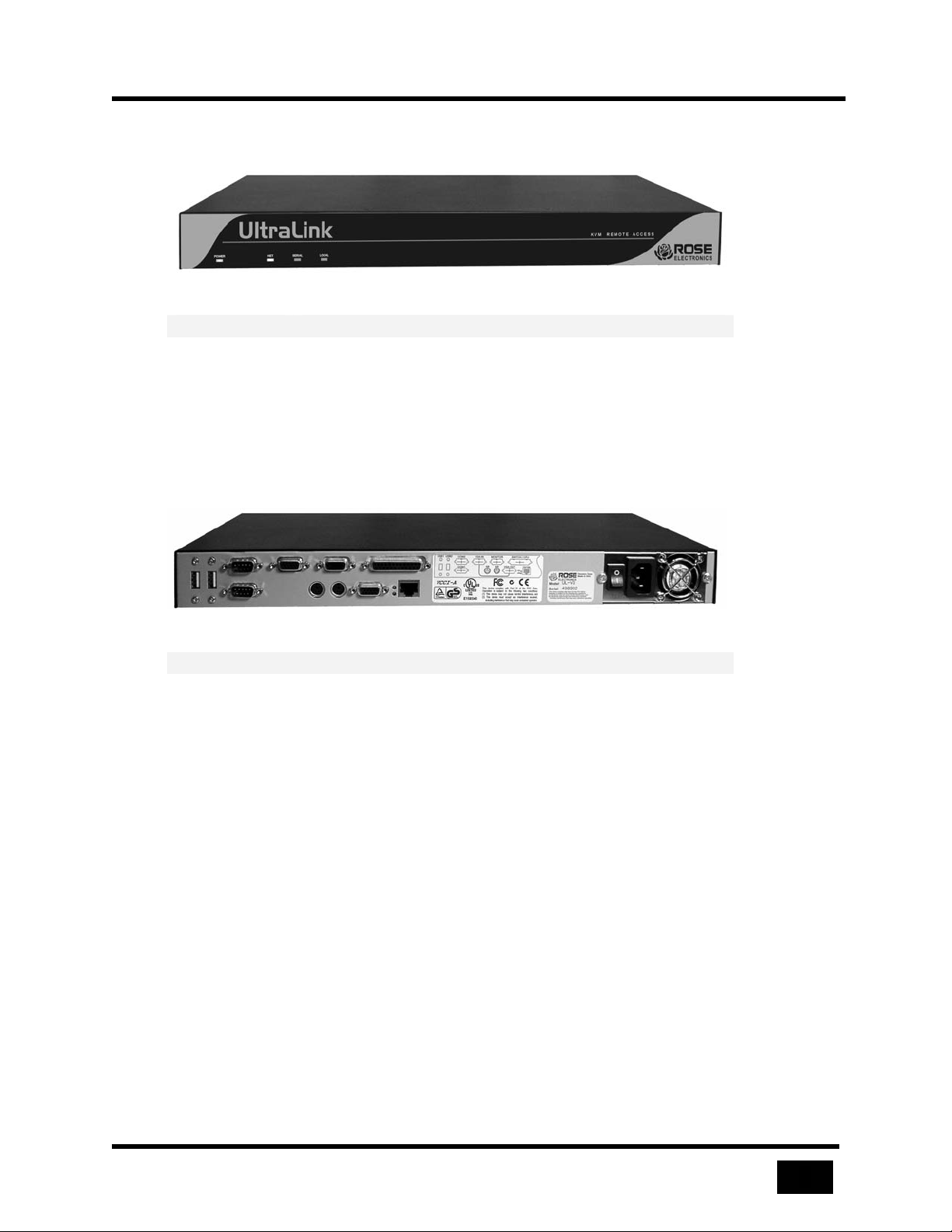
5
Front Panel
Figure 1 Front panel lamps indicate state of the UltraLink
Lamp Indication
POWER AC Power is applied
NET TCP/IP user logged in
SERIAL Serial device user logged in
LOCAL Local user is logged in
Table 1 Front panel indicators
Back Panel
Introduction
Figure 2 External connections on the back panel
Connector Usage
USB USB ports reserved for future use
COM1/COM2 Serial ports used for modem and reserved for
future use
KEYBOARD Connects to PS/2 keyboard
MOUSE Connects to PS/2 mouse
MONITOR Connects to monitor (local port used)
VGA-IN Connects to loop cable (local port used)
VGA-OUT Connects to loop cable (local port used)
or monitor (local port not used)
SWITCH/CPU
NETWORK Connects to 10MB / 100MB Ethernet interface
POWER 115 / 230 VAC, 50-60 Hz Auto switching
Table 2 Back panel connectors
Connects to user side of KVM switch
or standalone computer
Page 24
Getting Started
6
Getting Started
In the Box
The following items are included with your UltraLink:
UltraLink unit
Power cord
Cable from UltraLink to Rose switch (DB25 male to DB25 male)
Cable from UltraLink to standalone computer or other KVM switch (DB25 male to
VGA-PS2-PS2 male
Video loop cable used when local port is connected (VGA to VGA)
UltraLink Viewer software (two diskettes)
19” rack-mount brackets
UltraLink manual
Quick start guide
You Will Need
You will need the following items to connect and use your UltraLink:
Active Ethernet TCP/IP network
RJ-45 network cable
Standalone computer or KVM switch to be viewed and accessed
PC on network to have Viewer software loaded and act as Viewer
PC keyboard with PS/2 connector
PS/2 mouse (optional)
VGA monitor
This product is not intended for connection to
telecommunication network voltages (TNV) circuits
Page 25
Connections
7
SWITCH/CPU
NETWORK
KEYBOARD
MONITOR
MOUSE
SWITCH/CPUNETWORK
VIDEOLOOPCABLE
KEYBOARD MONITORMOUSE
Connections
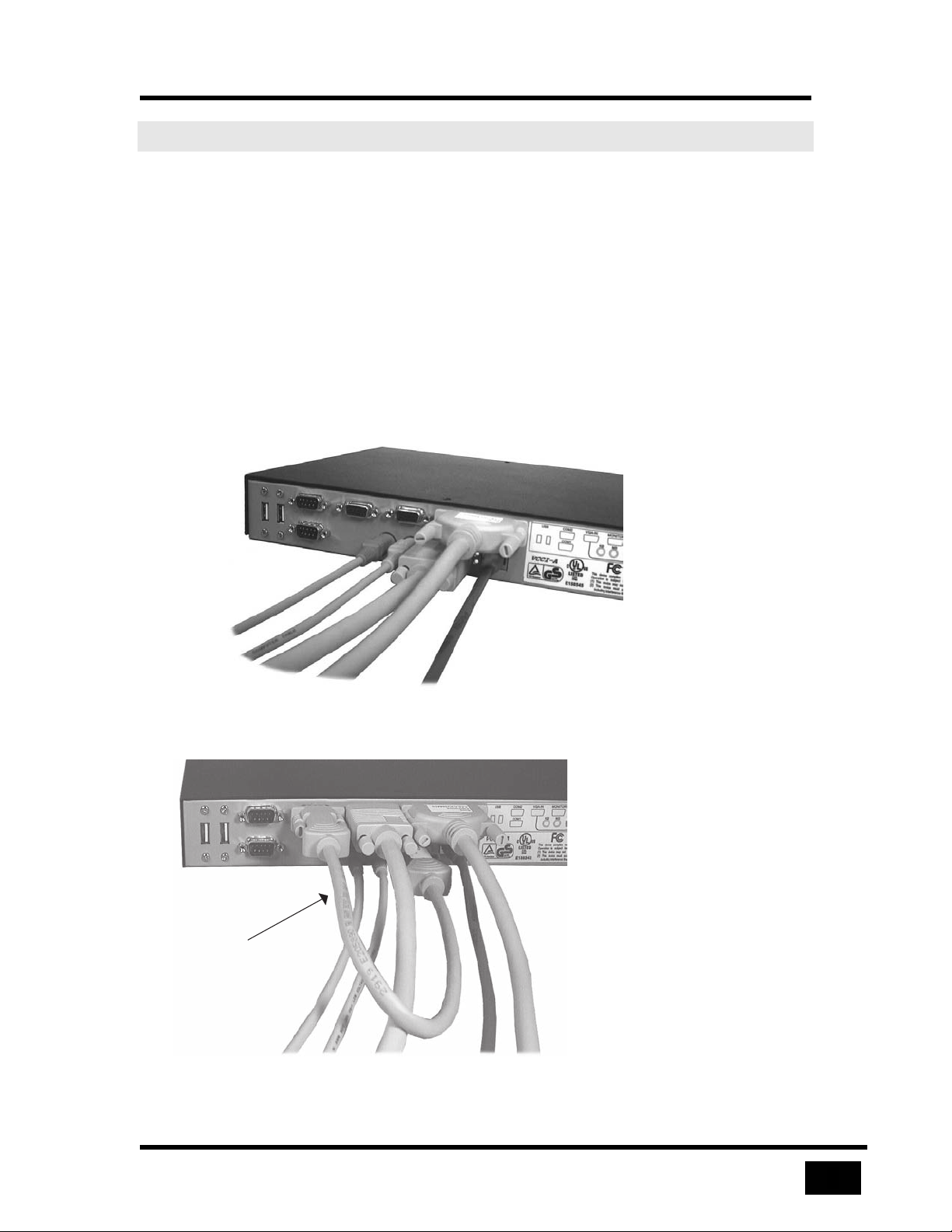
There are two ways to connect the UltraLink
The local KVM is a KVM station connected directly to the UltraLink. It can access
the Switch/CPU device attached to the UltraLink with the connect login described
later. If you don’t need the local KVM (example in the Quick Start Guide) then
connect the cables as shown in Figure 3. This simplifies the cabling and allows you
to view the power up progress of the UltraLink. The keyboard, monitor, and mouse
can be removed after using them to configure the UltraLink’s IP address.
If you require the local KVM, connect the cables as shown in Figure 4. When
connected in this way, you will not see anything on the local monitor until the
UltraLink completes its power-on process (about 25 seconds).
Figure 3 Cable connections, local KVM not used
Figure 4 Cable connections, local KVM used
Page 26
Start Up
8
Start Up
Power On
Connect the UltraLink to a power source and turn the power switch on. If the green
power led on the front panel does not illuminate, turn the power off, check your
power source, and wait at least 15 seconds before turning power on again.
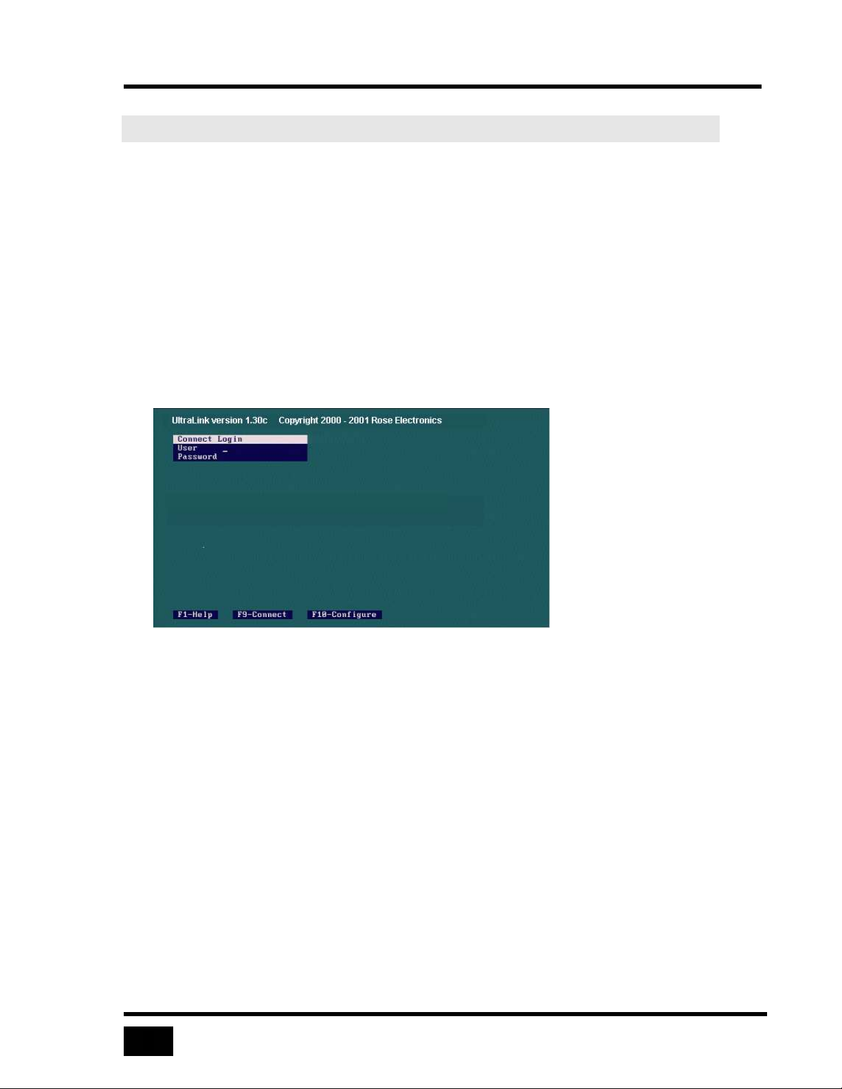
After the UltraLink completes a self-test and start-up, it displays the connect login
screen. If you have connected the video loop cable, your monitor may remain blank
for up to 25 seconds before a login screen appears.
If no login screen appears, check the connections as shown in Figure 3.
Figure 5 The connect login screen
Page 27
9
About Logins
A default administrator account exists for initial configuration when the UltraLink
first starts up. The user ID is admin and there is no password.
IMPORTANT One of the first steps an administrator should perform is to secure
the user ID and password for the default administrator account.
Change them with the UltraLink Viewer using the default account
and the Security Settings dialog. If you forget the administrator
user ID or password, override the user ID and password check as
described in Password Defeat.
There are two types of logins:
• Connect login — connects the local KVM to the Switch/CPU device attached
to the UltraLink
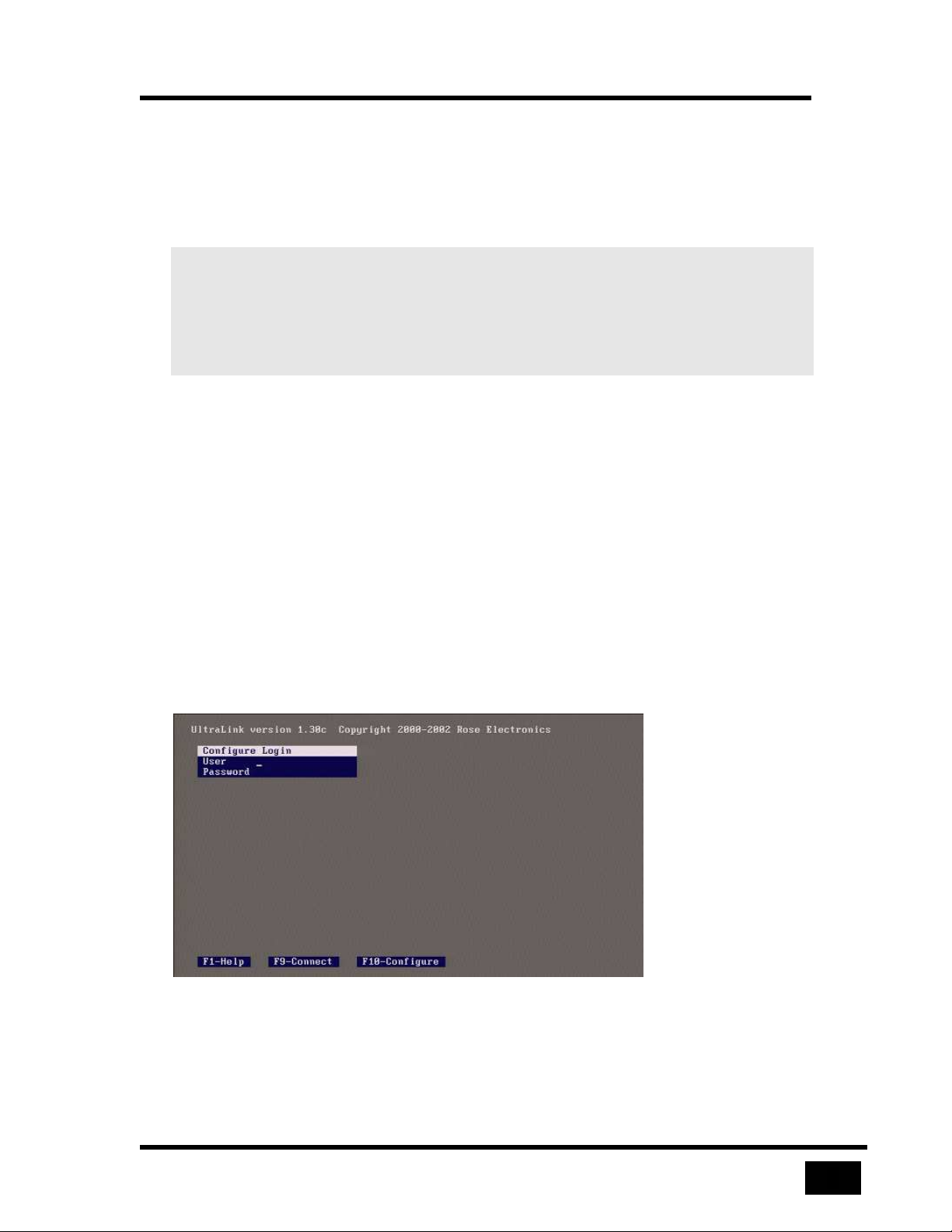
• Configure login — configures the IP address
Start Up
Press the F9 key to display the connect login screen or the F10 key to display the
configure login screen. Each screen is a different color. You must use the
administrator user ID for the configure login.
You may press the F1 key to view help text on a login screen. Press F1 again to
remove the help text from the screen.
Figure 6 The configure login screen
Page 28
Start Up
10
Using Configure Login for the First Time
Only basic communication settings are required on the UltraLink to make it
accessible to a Viewer. An administrator performs other settings, such as user
management, security, and switch configuration from the UltraLink Viewer program.
To configure the UltraLink for remote login by the UltraLink Viewer program, enter
a TCP/IP address as follows:
• Press F10 to display the gray configure login screen.
• Login at the configure login screen using Rose as user name and no password.
• Enter IP address, subnet mask, and gateway address.
• Press F10 to save the configuration data and to return to connect login screen.
The changes are effective immediately.
Using Connect Login for the First Time
Perform the following steps to verify cable installation and to access the device
connected to the Switch/CPU port from the UltraLink local KVM.
• Press F9 to display the green connect login screen.
• Login at the connect login screen using admin as user ID and no password.
• Verify that the keyboard, mouse, and video perform properly.
• Press Ctrl, Alt, and the L key simultaneously to exit the connect login.
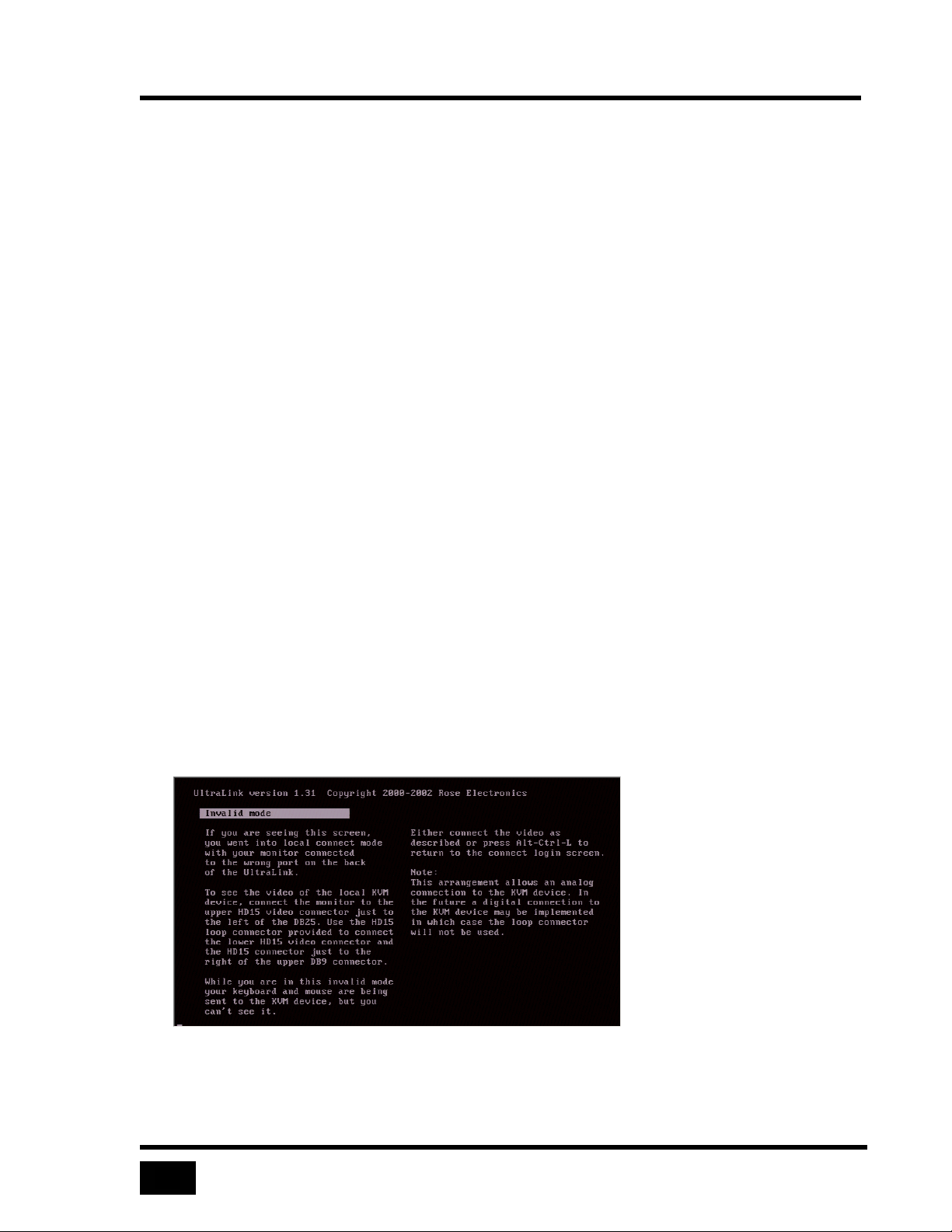
If you do not see the video of the connected device or see an invalid mode screen,
check the cable connections as shown in Figure 4.
Figure 7 Invalid mode screen
Page 29
11
IMPORTANT To exit the connect login screen, press Ctrl, Alt, and the L key
simultaneously.
The Configure Screen
Move between fields on the configure screen by pressing the up and down arrow
keys. As you move from one field to another, values are validated. If you enter an
invalid value, the arrow keys do not function until you either correct the value or
press the Esc key. If you press the Esc key, the original value is restored in the field.
Edit within a field by using left and right arrow keys, and the delete and backspace
keys.
IP Address
The UltraLink uses a fixed IP address. Change the default address to permit remote
access by the UltraLink Viewer program. Enter a valid IP address in the standard
dotted-decimal format, e.g. 192.168.1.71.
Subnet Mask
Start Up
Enter a valid subnet mask in the subnet mask field, e.g. 255.255.255.0. The
UltraLink does not apply an invalid subnet mask and reverts to the last known good
subnet mask.
Gateway
Gateway is an optional field. Enter a gateway address to allow access to the
UltraLink from networks other than the one defined by IP address and subnet mask.
Enter a valid IP address in the standard dotted-decimal format, e.g. 192.168.1.1.
Figure 8 The configure screen
Page 30
Start Up
12
Saving or Abandoning Changes
Press the F10 key to apply network settings immediately and to make the UltraLink
available to Viewers on the network. Press F9 to cancel the changes. After saving or
canceling your changes, the connect login screen is displayed. To change the
settings, login again at the configure login screen.
Connect Contention
The UltraLink disallows a connection to the local KVM and a Viewer at the same
time. If you login as an administrator, and a Viewer is connected, you send a
message to the Viewer indicating that an administrator has logged in and you
disconnect the Viewer.
As a security precaution, you must login again after disconnecting the Viewer. This
protects against the possibility that you are using the Viewer to login to the local
KVM port (connected to a KVM switch) of the UltraLink that connects to your
Viewer. Instead of logging in and disconnecting yourself, leaving the UltraLink
logged in, you must login again.
If you login with a non-administrator account, the connect login fails and the remote
connection is unaffected.
Password Defeat
If you forget the administrator’s user ID or password, remove the cover of the
UltraLink and place a jumper on the pins labeled, PASSWORD DEFEAT. When this
jumper is in place, a connect login or configure login succeeds with any user ID and
password and the login will be as an administrator. Once logged in, set a new
administrator user ID and password. A reminder that the PASSWORD DEFEAT
jumper is place displays on the UltraLink login screens and when a Viewer logs in.
Page 31
Installing the UltraLink Viewer
13
Installing the UltraLink Viewer
Requirements
The UltraLink Viewer runs on most Windows PC installations.
Minimum Hardware
• 133 megahertz PC with 32 Mb of system memory and 4 Mb of free disk space
• VGA display adapter and monitor, capable of 640 x 480 resolution
• Keyboard and mouse
Microsoft Windows
• Microsoft Windows 95 or above
• Network connection with TCP/IP protocol
The Setup Wizard
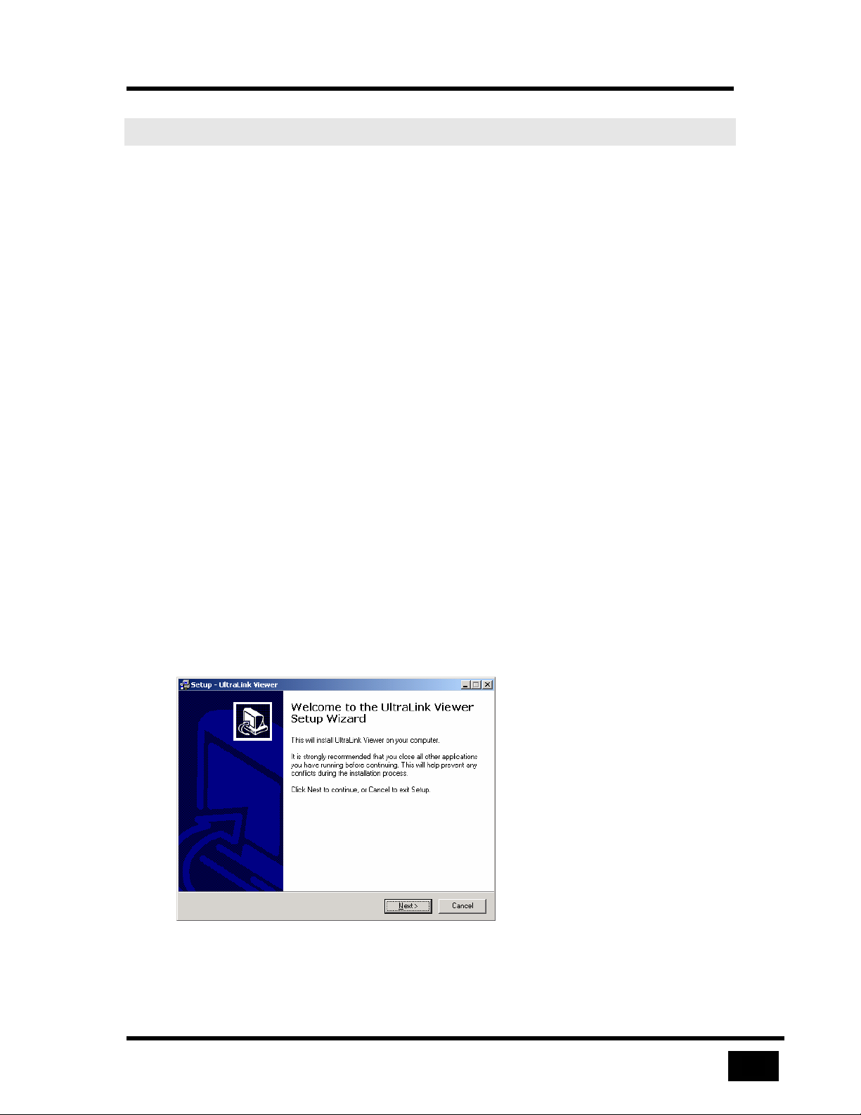
The Setup Wizard guides you through installation of the UltraLink Viewer.
Look for the setup file to install the UltraLink Viewer:
• On setup media included with the UltraLink unit
• From the UltraLink web page at www.rosel.com/htm/supportulfirmware.htm
`
Figure 9 The Setup Wizard
Page 32
Installing the UltraLink Viewer
14
You may choose the folder in which you install the Viewer. Start the Viewer using
one of the items optionally created by the Setup Wizard: Desktop icon, Quick
Launch icon, or Windows Start Menu entry.
Using the Viewer for the First Time
IMPORTANT Pass-through mode takes control of your keyboard and mouse
away from your computer and passes it to a remote computer
attached to the UltraLink. To regain control of your computer’s
keyboard and mouse: hold down the Ctrl, Alt and P keys
simultaneously. You may also use mouse escape movements
defined in the Settings menu to exit pass-through mode.
Full-screen mode takes control of your monitor and uses the
whole screen to display a remote computer’s screen. To regain
control of your monitor, hold down the Ctrl, Alt and F keys
simultaneously. Exiting pass-through mode also returns control
from full-screen mode.
Connect
Click the Connect icon in toolbar of the UltraLink Viewer and wait for the login box
to appear.
Login
Login with the default administrator account: admin user name and no password.
After a moment, you should see the video attached to the UltraLink. When the passthrough warning message appears, click the OK button to forward your local
keyboard and mouse to the remote computer. If you are prompted with the fullscreen warning message, click the Cancel button.
Administrator Tasks
If you are an administrator, you may also change the default administrator account
user ID and password at this time. Other administration tasks are:
• Add user IDs and passwords
• Specify the type of encryption between the UltraLink and a Viewer
• Add an inactivity disconnect timer for Viewers
• Enable KVM switch features in the Viewer
Page 33
15
The Viewer Screen
The Viewer screen contains the following functional areas:
•
Title bar
•
Menu commands
Display area
•
•
Toolbar
•
Status bar
Windows buttons
•
•
What’s this help
•
Message dialogs
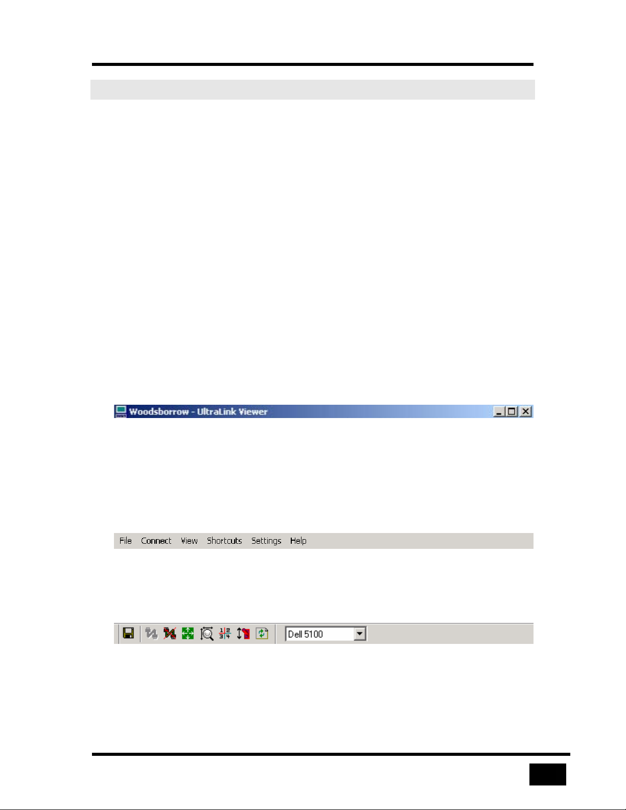
The Title Bar
The Viewer Screen
When the Viewer is not connected to an UltraLink, the title bar displays the name of
the program, UltraLink Viewer. When a connection is active, the Viewer also
displays the name of the connection defined in the Connections dialog in the title bar.
Figure 10 This title bar displays an UltraLink location
Menu Commands
Menus, positioned below the title bar, describe commands and options to operate the
Viewer.
Figure 11 Menu commands
The Toolbar
Figure 12 The toolbar icons and a remote computer select list
Page 34
The Viewer Screen
16
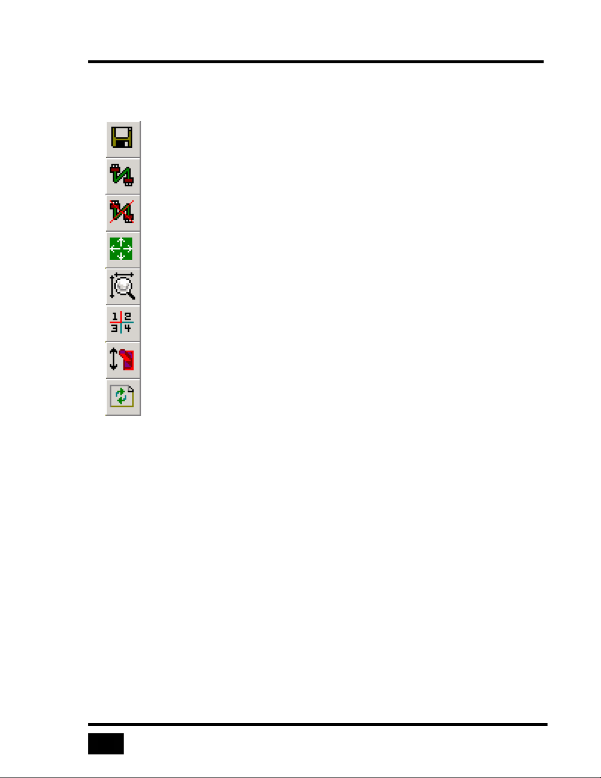
Toolbar Icons
The toolbar provides quick access to the following functions:
Save bitmap
Connect
Disconnect
Full-screen
Auto size
Quad-screen
Ctrl + Alt + Delete
Refresh
Table 3 Toolbar icons
UltraLink Location List
When the Viewer is not connected, an UltraLink location list box is visible. When
you select an UltraLink name in the list box, you may connect by selecting the
connect toolbar icon. After connection, the list box disappears.
Remote Computer Select List
When you connect to an UltraLink with a KVM switch, a remote computer select list
replaces the UltraLink location list. Select a computer in the remote computer select
list to switch your keyboard, monitor, and mouse to that computer.
The Display Area
The display area contains a real-time image of one or more remote computers. In
quad-screen view, the display area contains images of up to four remote computers.
Page 35
The Viewer Screen
17
The Viewer may scale images to fit into the display area or display images at the
same resolution as the remote computer. View menu commands control the
appearance of images in the display area.
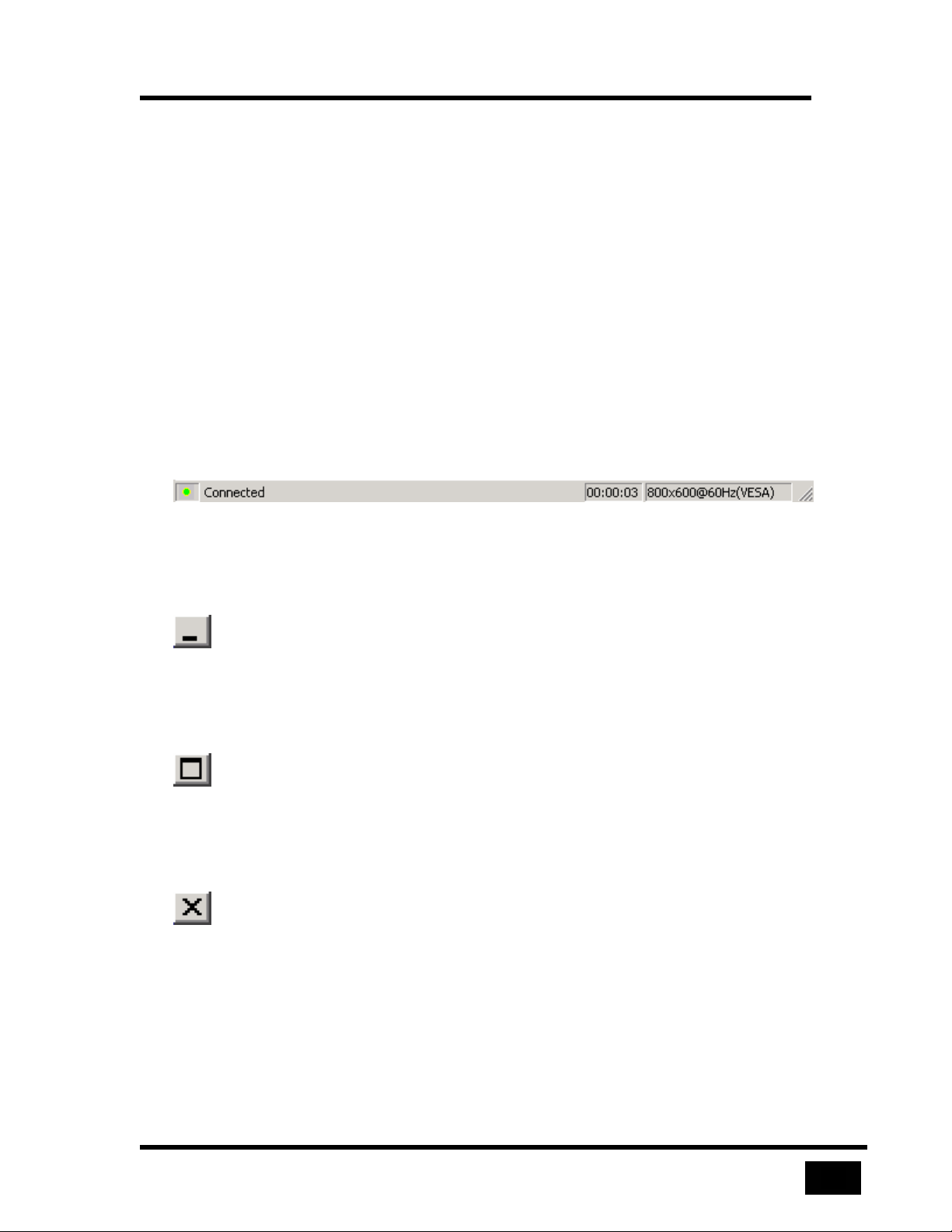
The Status Bar
The status bar, at the bottom of the Viewer window, provides the following items:
• Pass-through led indicator to indicate whether your video, keyboard and
mouse are connected to a remote computer
• Text describing a current menu selection or pass-through mode exit method
• A connection timer
• Description of the video resolution displayed in the display area
Figure 13 Status bar
Windows Buttons
Minimize
The minimize button brings the Viewer screen to the size of an icon in the Windows
taskbar. If you are logged in, the UltraLink continues to refresh the display area’s
view, even though it is not visible.
Maximize
The maximize button allows the Viewer to cover the complete screen This differs
from full-screen mode in that the title bar, menus, toolbar, and status bar are all
visible.
Exit
The exit button disconnects the Viewer from an UltraLink and terminates the Viewer
application.
Page 36
The Viewer Screen
18
Question Mark Help
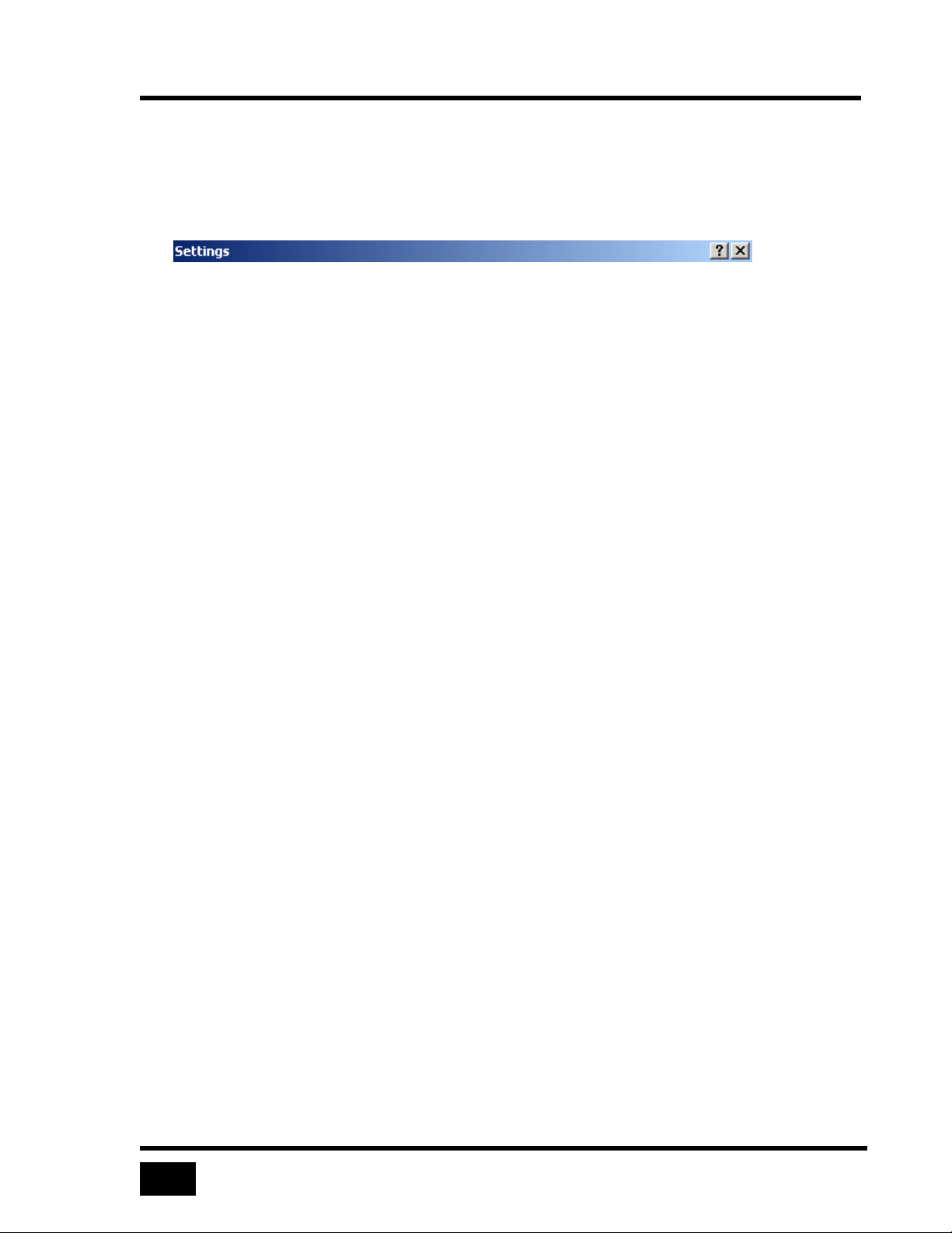
On some dialogs, there will be a small question mark in the upper right hand corner.
Click on the question mark, and then click on a field in the dialog to get help on that
specific item.
Figure 14 Question mark help
Page 37
Menu Commands
19
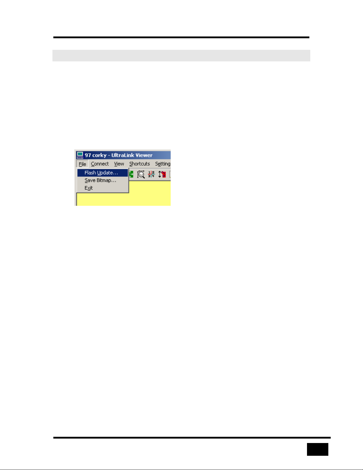
Menu Commands
File
The File menu contains the following commands as shown in the figure below:
• Flash Update
• Save Bitmap
• Exit
Figure 15 File menu commands
Flash Update
The Flash Update command, available to administrators, allows the Viewer to update
an UltraLink with new firmware. The command prompts for the name of a flash
update file. Flash update file names take the form ulpxxx.bin, where xxx is an
update version. When an upload completes, the UltraLink breaks the connection with
the Viewer and restarts to activate the new firmware. Wait at least one minute before
reconnecting to the UltraLink.
Save Bitmap
This command saves the image in the Viewer display area to a bitmap file. In
screen
display area only and not the title bar, menus, toolbar or status bar. This operation is
available only when you are logged in to an UltraLink.
Exit
The Exit command causes the Viewer application to terminate execution. If the
Viewer is logged in, the Viewer exits pass-through mode and disconnects before
closing.
view, all the quadrants are saved to the bitmap file. The Viewer saves the
quad-
Page 38
Menu Commands
20
Connect
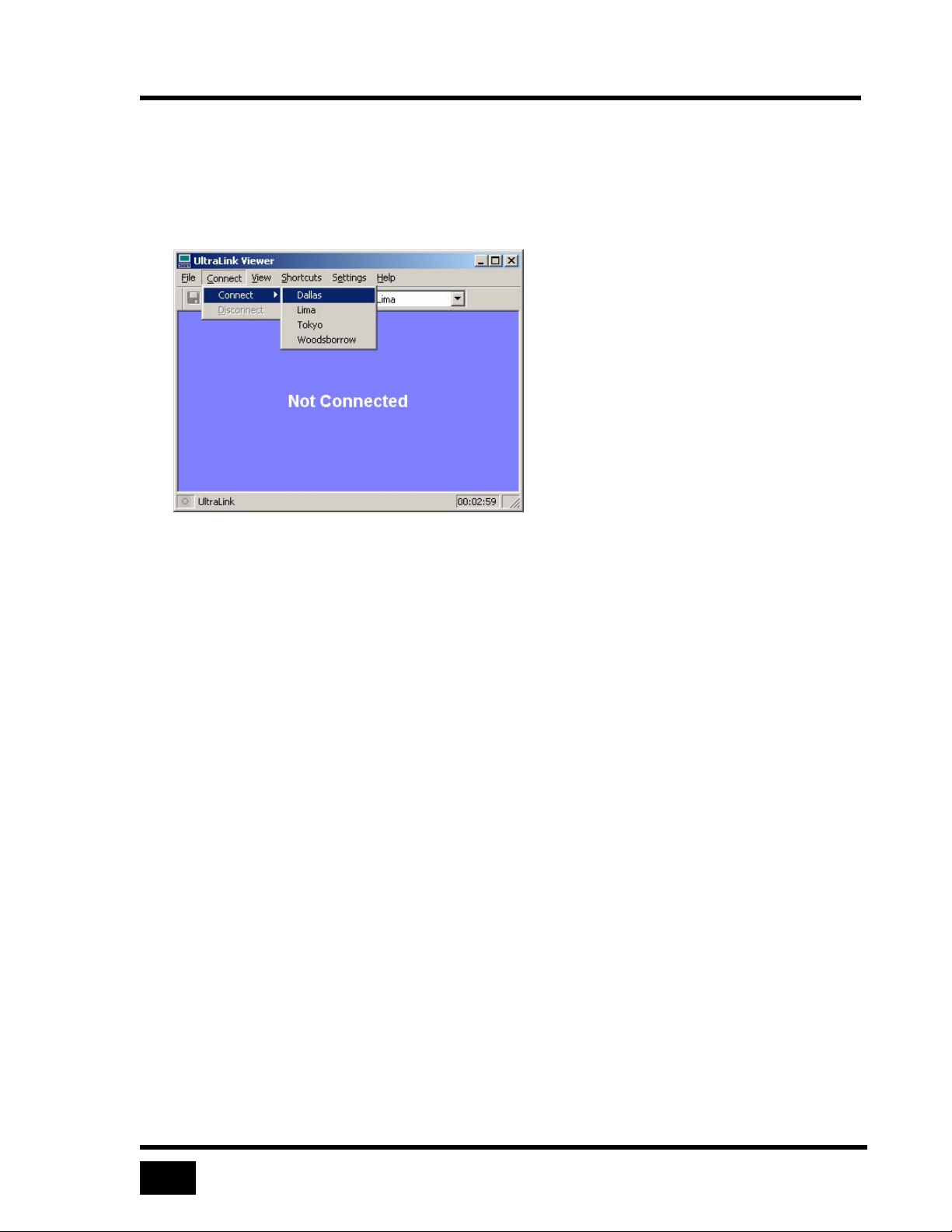
The Connect menu contains the Connect and Disconnect commands. See also
Connecting and Logging In.
Connect
Figure 16 Connect command
The connect command displays all UltraLink units configured by the Viewer. You
may select any UltraLink on the menu to initiate a connection.
Disconnect
Selecting the Disconnect command disconnects the Viewer from the UltraLink. The
Disconnect command is enabled when the Viewer is connected and is disabled when
not connected.
View
View menu commands control the remote computer’s image in the display area. See
also
View Modes.
Page 39
21
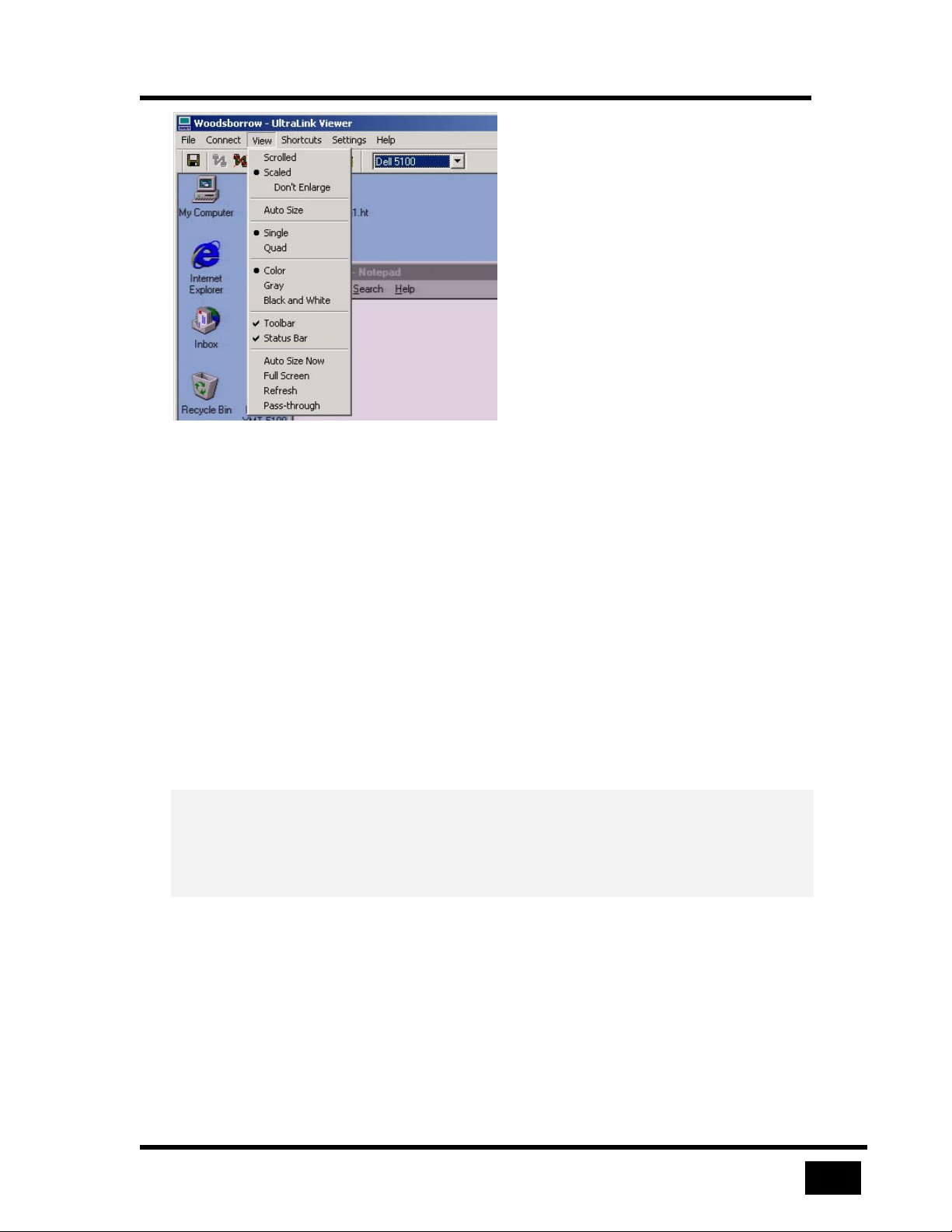
Figure 17 View commands
Scrolled
Menu Commands
In scrolled view, the remote computer’s video image displays in its native resolution,
providing the sharpest image. If the Viewer display area is not large enough to
display the image horizontally or vertically, scroll bars appear to allow viewing any
part of the image.
Scaled
In scaled view, the remote computer’s video image is squeezed or stretched to fit in
the display area. When you change the size of the display area, the image changes to
fit into the new size.
Don’t enlarge
At times, you may prefer to keep your window size constant and inhibit the Viewer
from enlarging the display area. This is particularly true when switching between
remote computers on a KVM switch. If you check the Don’t Enlarge sub-option,
images larger than the display area are scaled and images smaller than the display
area are centered.
Auto Size
The Auto Size sub-option performs an Auto Size Now command when the Viewer
displays a new video resolution in the display area. See the Auto Size Now command
below for more information.
Page 40
Menu Commands
22
Single
Single screen view, as opposed to quad-screen view, is the default display view. The
Viewer enters single screen view on logging into the UltraLink. In single screen
view, the video image from only one remote computer shows in the display area. If
the UltraLink is not connected to a switch, the display area shows the image of the
remote computer connected to the UltraLink.
Quad-screen
Quad-screen view is not available unless the UltraLink connects to a KVM switch.
The Viewer displays video from up to four remote computers at the same time by
controlling the KVM switch. In quad-screen view, mouse and keyboard input does
not connect to any of the four remote computers, and pass-through mode is disabled.
The Viewer divides the display area into four quadrants and a computer select box
for each quadrant of the screen appears on the toolbar.
Color
The image displays in color. See also
Gray
The image displays in 256 shades of gray.
Black and White
The image displays in black and white only.
Toolbar and Status Bar
You may select the toolbar and status bar to not display, providing more viewing
space at the cost of convenience.
Auto Size Now
Auto Size Now attempts to size a remote computer’s image in the display area using
the best possible resolution. If the remote image is smaller than the display area, the
image appears centered in the display area. If the image is larger than the display
area, the Viewer increases the window size to display the image at the remote
computer’s resolution. However, if the image is larger than what may be viewed on
your computer, the Viewer maximizes to fill your screen. If the remote computer’s
resolution is the same as your computer, Auto Size maximizes the window to fill
your screen.
Color Modes.
You may also select the Auto Size Now command using the toolbar icon.
Page 41
Menu Commands
23
Full Screen
In
full-screen mode, the display area takes over the entire screen area of your
computer. The title bar, menus, toolbars, and status bar of the Viewer are not
displayed – only the video image of the remote computer is visible on the screen.
message dialog displays a warning on entering full-screen view. The message
A
gives a brief description of full-screen view and the means of exiting it. A checkbox
at the bottom of the message dialog allows you to suppress the display of the dialog.
Refresh
The Refresh command, also invoked with a button on the toolbar, causes the
UltraLink to resend the current screen image.
Pass-through
The Pass-through command causes the Viewer to enter pass-through mode.
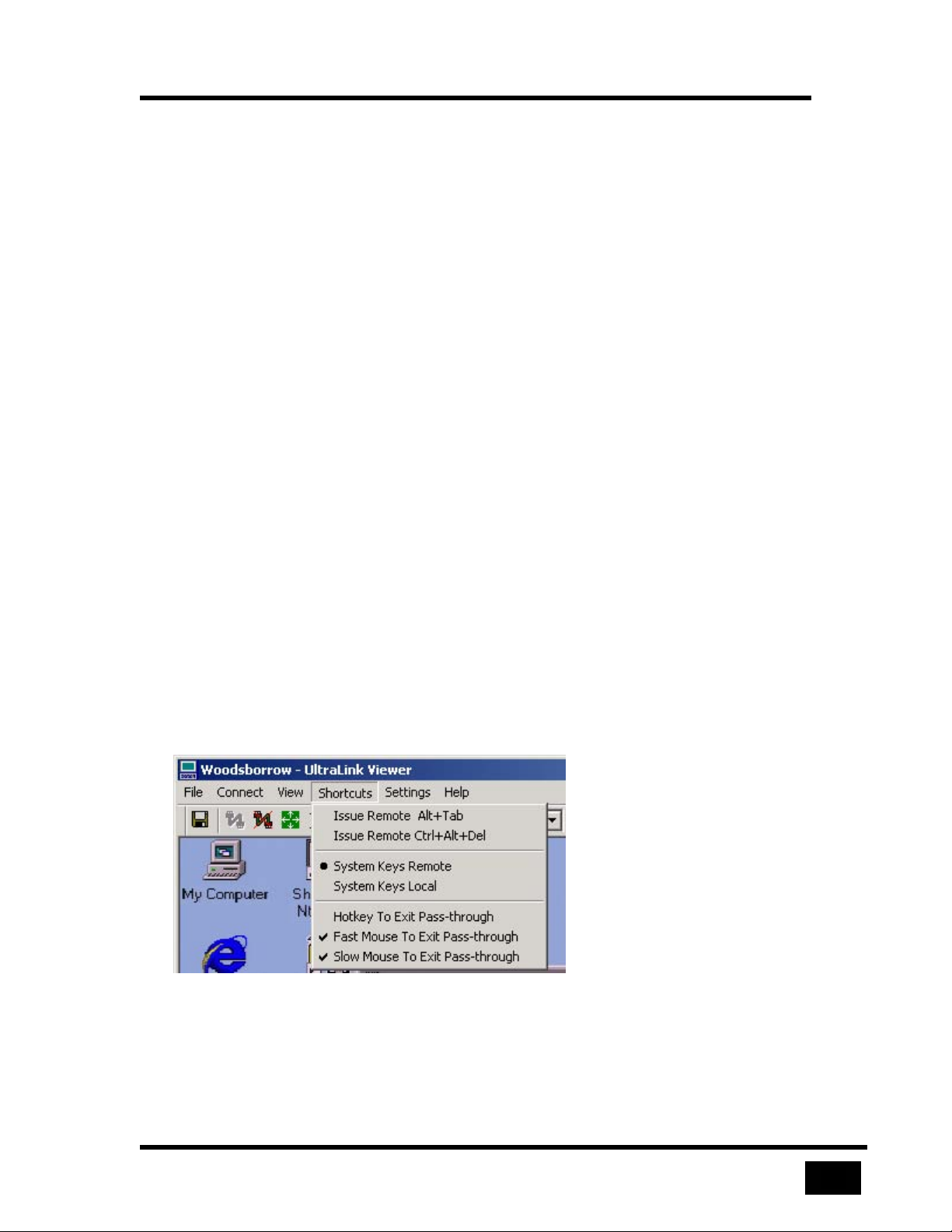
Shortcuts
As a convenience, the Shortcuts menu provides methods to:
• Issue the Windows operating system keyboard functions, Alt+Tab and
Ctrl+Alt+Delete to the remote computer immediately
• Direct certain system keys to your computer or to the remote computer while
you are in pass-through mode
• Turn hotkeys and mouse escape movements on or off
Figure 18 Selecting shortcuts
Page 42
Menu Commands
24
Issue Remote Alt+Tab
Send the Alt and Tab keys to the remote computer as if they were pressed
simultaneously.
Issue Remote Ctrl+Alt+Del
Send the Ctrl, Alt and Delete keys to the remote computer as if they were pressed
simultaneously.
System Keys Remote and System Keys Local
system keys to the remote computer or to your computer. See the section, Pass-
Send
through Mode on page 40, for information about system keys.
Exiting Pass-through Shortcuts
See the section, Pass-through Mode on page 40, for information about pass-through
mode. See the section Keyboard and Mouse on page 30 for information about
hotkeys and mouse escape movements.
At least one of the following shortcuts must be active or it would be impossible to
escape
automatically enables keystrokes.
pass-through mode. If you attempt to deactivate all methods, the Viewer
• Hotkey To Exit Pass-through
• Fast Mouse To Exit Pass-through
• Slow Mouse To Exit Pass-through
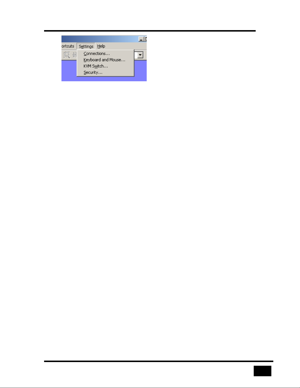
Settings
The Settings menu contains tabbed dialogs to configure both the UltraLink and the
UltraLink Viewer. Except for basic communications settings, the UltraLink is
configured from the Viewer using the KVM Switch and Security tabs. The Viewer is
configured using the Connections and Keyboard and Mouse tabs. See the
Configuration Settings section for a full description of each tab of the Settings
dialog.
Page 43
Menu Commands
25
Figure 19 Settings commands display a tabbed dialog
Connections
The Connections tab allows you to maintain a list of UltraLink locations to which the
Viewer may connect.
Keyboard and Mouse
The Keyboard and Mouse tab defines special key sequences and mouse escape
movements to exit pass-through mode on the Viewer.
KVM Switch
The KVM Switch tab maintains names associated with KVM ports and keyboard
events used to switch to a KVM port. UltraLink KVM switch settings are managed
from the Viewer by an administrator. If the Viewer is not logged in to an
administrator account, the KVM Switch tab is unavailable.
Security
UltraLink security settings are managed from the Viewer by an administrator. If the
Viewer is not logged in to an administrator account, the Security tab is unavailable.
Page 44
Menu Commands
26
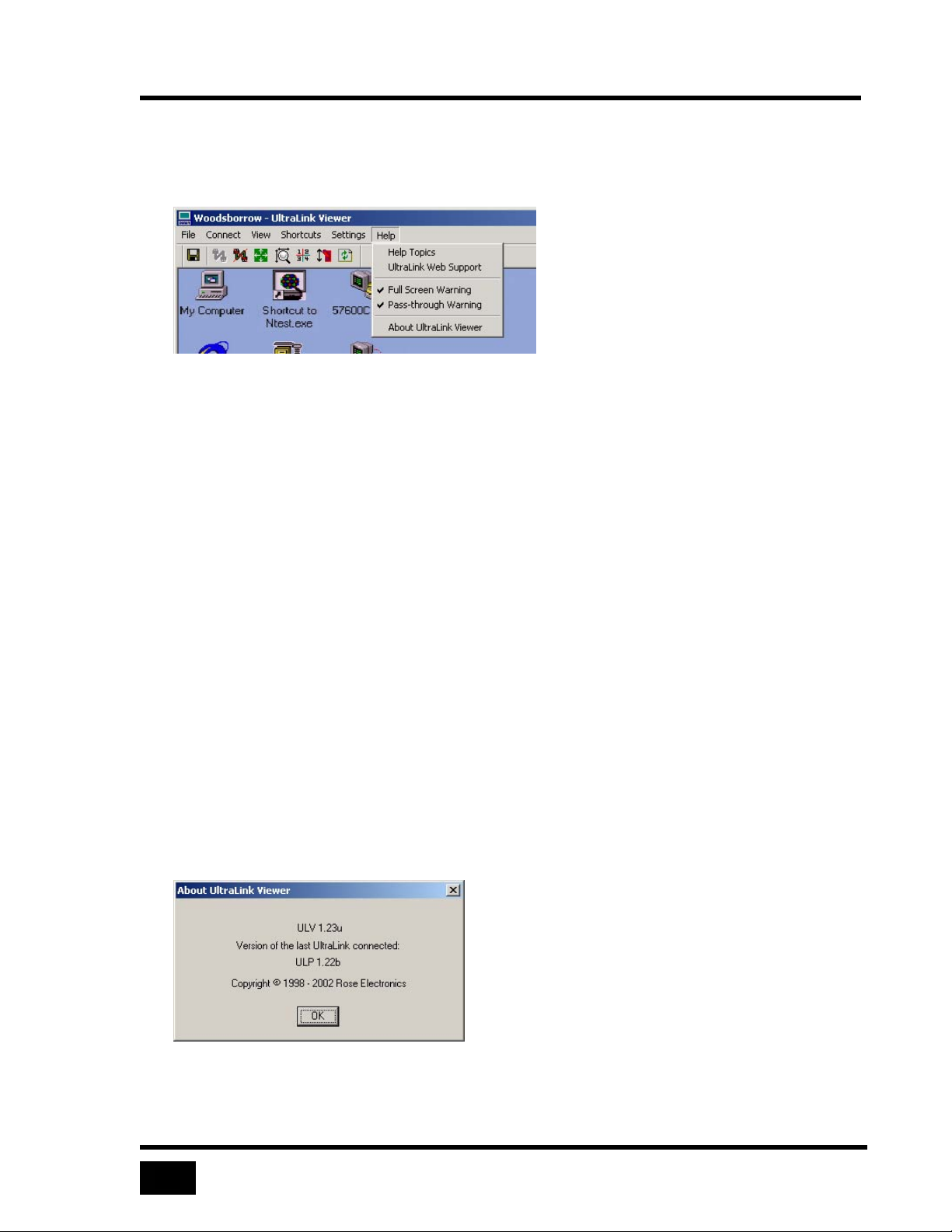
Help
Help is available in various forms.
Figure 20 Help menu
Help Topics
The Help Topics command invokes full online help.
UltraLink Web Support
The UltraLink Web Support menu option opens a browser and links to the support
web site.
Full Screen Warning
Enable or disable the warning dialog that appears before a switch to
.
mode
Pass-through Warning
Enable or disable the warning dialog that appears before a switch to
mode
.
About UltraLink Viewer
About UltraLink Client gives information about the current version of the Viewer
and the last UltraLink that was connected.
Figure 21 The About Box
full-screen
pass-through
Page 45
Configuration Settings
27
Configuration Settings
The Settings menu item contains a tabbed dialog to configure the UltraLink and the
UltraLink Viewer. Configure the Viewer with the
Mouse
may configure the UltraLink using the
settings are stored on the UltraLink.
The following buttons appear at the bottom of the tabbed dialog and remove the
Settings menu from view.
OK
tabs. Settings are stored on your computer. If you are an administrator, you
KVM Switch and Security tabs. These
The OK button applies changes made in all tabs to the Viewer immediately. If
an administrator changes items in the KVM Switch or Security tabs, the changes
are saved on the UltraLink and the changes are effective at the next login. KVM
switch settings are active immediately.
The Viewer disables the OK button if another configuration dialog, such as the
User Details dialog of the Security tab is open. Close the dialog to enable the
OK button at the bottom of the Settings tabbed dialog.
Connections and Keyboard and
Cancel
The Cancel button discard changes you make in all tabs.
Page 46
Configuration Settings
28
Connections
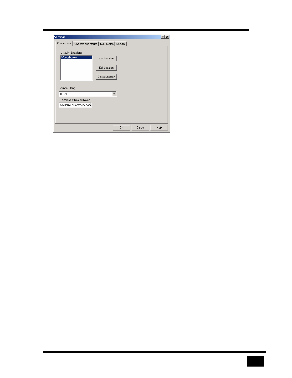
The Connections tab displays and maintains a list of UltraLink locations to which a
Viewer may connect. A location is a name of your choosing to identify the
UltraLink.
UltraLink Locations
Three items describe each UltraLink location in the list: location name, connection
type, and address. When you select a location in the list, the Viewer displays
corresponding parameters in the Connect Using and IP Address fields. You may add,
rename, or remove a location using the Add Location, Edit Location and Delete
Location buttons. Changes made in the Connection Settings dialog reflect in the
Connect menu and in the Connect Selection box on the toolbar.
The buttons bring up a dialog. On entering the dialog, the currently selected location
in the UltraLink select list box on the toolbar displays. The location may not be
edited or deleted if the Viewer is connected to that location. On leaving the dialog,
the location selected in the list is also selected in the UltraLink select list box on the
toolbar.
Add Location
The Add Location button define a new location to be added to the list of UltraLink
locations. A dialog is provided where the name of the new location can be specified.
After adding the location, it is selected so that its parameters can be defined.
Edit Location
The Edit Location button brings up a dialog to change the name of the location.
Because the UltraLink locations list is sorted, renaming the location may change its
position in the list.
Delete Location
The Delete Location button removes the selected location from the list.
Connect Using
The only valid choice is TCP/IP at this time.
IP Address or Domain Name
This field specifies a TCP/IP address or domain name of an UltraLink to which the
Viewer may connect. A TCP/IP address takes the form: nnn.nnn.nnn.nnn. A
domain name: ultralink.mycompany.com.
Page 47
29
Figure 22 An UltraLink address
Configuration Settings
Page 48
Configuration Settings
30
Keyboard and Mouse
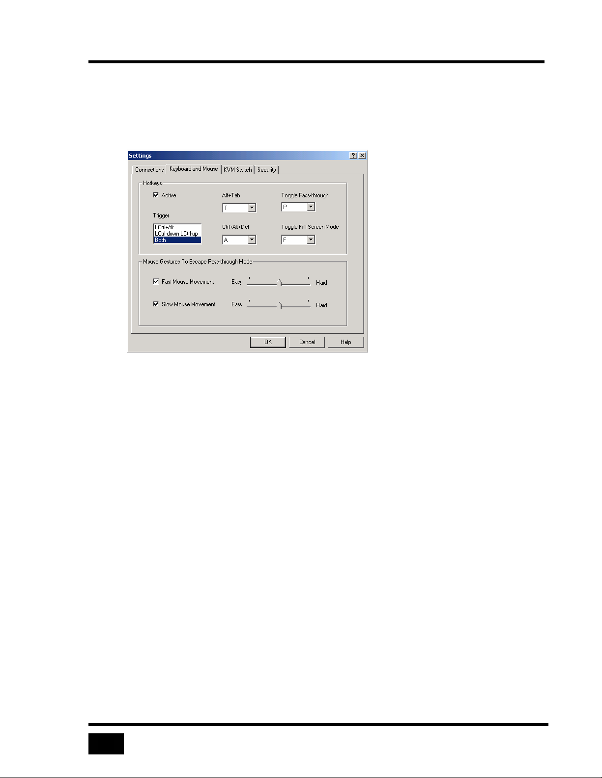
The Keyboard and Mouse tab defines hotkeys and mouse escape movements.
Hot Keys
Hotkeys use keystrokes to perform the following actions:
• Enable or disable
• Enable or disable
• Send Ctrl+Alt+Del to a remote computer
• Send Alt+Tab to a remote computer
Activate hot keys in one of two ways: simultaneously press the Ctrl and Alt keys and
hotkey, or press and lift the Ctrl key and then press a hot key within 2 seconds. The
second option provides an alternative in case the first option conflicts with an
application on the remote computer. For example, Ctrl+Alt+P is also a command in
Microsoft Word. Note that the second option may conflict with function keys on a
KVM switch.
You may choose any letter in the alphabet to represent a hotkey, as long as it is not
used as another hotkey.
pass-through mode
full-screen view
Active
The Active checkbox enables the hotkey fields in the dialog. If you clear Fast
Mouse Movement and Slow Mouse Movement in the check boxes on the same
dialog, the Viewer automatically checks the Active checkbox to prevent you
from disabling all methods of exiting pass-through mode.
Trigger
The Trigger list defines key sequences to activate a hotkey. The options are Ctrl
+ Alt, Ctrl-down Ctrl-up, and Both. The Ctrl + Alt key enables the hotkey if you
hold down the Ctrl, Alt and the hotkey at the same time. The Ctrl-down Ctrl-up
key sequence enables the hotkey if you press and release the left Ctrl key and
then press and release the hotkey. Both indicates that both the Ctrl + Alt and the
Ctrl-down Ctrl-up key sequences may be used.
Alt+Tab
The Alt + Tab hotkey sends an Alt + Tab key sequence to the remote computer
and does not depend on whether the Viewer is in pass-through mode or not.
Page 49
Configuration Settings
31
Ctrl+Alt+Del
The Ctrl + Alt + Del hotkey sends a Ctrl + Alt + Delete key sequence to the
remote computer and does not depend on whether the Viewer is in pass-through
mode or not.
Toggle Pass-through Mode
The Toggle Pass-through Mode hotkey puts the Viewer into pass-through mode
if the Viewer is not already in pass-through mode and takes the Viewer out of
pass-through mode if the Viewer was in pass-through mode.
Toggle Full Screen Mode
The Toggle Full Screen hotkey puts the Viewer into full-screen view if the
Viewer is not already in Full Screen mode and takes the Viewer out of fullscreen view if the Viewer was in full-screen view.
Mouse Escape Movements
In addition to hotkeys, you may also use two types of mouse escape movements to
pass-through mode. Mouse escape movements only takes the Viewer out of
exit
pass-through mode and do not put the Viewer into pass-through mode.
• Fast mouse movement is moving the mouse using continuous rapid zigzag
motions for several seconds
• Slow mouse movement is a continuous long mouse movement in a single
direction.
Fast Mouse Movement
This checkbox, if enabled, allows you to escape pass-through mode using
continuous rapid mouse movement.
Activating the check box also enables a slider control to the right of the
checkbox. The slider controls mouse sensitivity for Fast Mouse movement.
Moving the slider to the left reduces mouse sensitivity and makes it easier to
escape pass-through mode. Moving the slider right increases the mouse
sensitivity and requires greater mouse movement to escape pass-through
mode.
Slow Mouse Movement
This checkbox, if enabled, allows you to escape pass-through mode using a long
mouse move in one direction.
Page 50
Configuration Settings
32
Activating the check box also enables a slider control to the right of the
checkbox. The slider controls mouse sensitivity for Slow Mouse movement.
Moving the slider to the left reduces mouse sensitivity and requires moving the
mouse a smaller distance. Moving the slider to the right increases mouse
sensitivity and requires longer mouse movement.
Figure 23 Configure hot keys and mouse escape movements
Page 51
Configuration Settings
33
KVM Switch
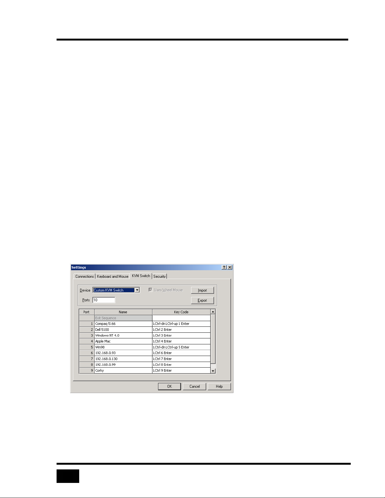
An administrator may use the Switch Settings tab to perform the following functions.
See the section
• Activate UltraLink KVM features of any Viewer that logs in to this UltraLink
• Name KVM switch ports to allow the names to appear in the remote computer
select list on the toolbar after a login
Device
The Device list box specifies the device type attached to an UltraLink – remote
computer or KVM switch. The device may be: standalone PC, one of the KVM
switches in the list, or custom. Use standalone PC if the UltraLink connects to a PC.
If you select standalone PC, all KVM switch features of the Viewer are disabled. If
you select a KVM switch from the list, you do not need to define keystrokes for port
switching, but you may assign symbolic names to the ports. If you select custom, you
must define the keyboard events that cause a KVM switch to switch from one port to
another.
Using a KVM Switch.
Ports
The Ports field specifies how many ports on the KVM switch are used. A standalone
PC device uses only one port, but you may specify the number of ports for other
devices. Change the number in the Ports field by typing a different number. Smaller
numbers remove existing entries at the end of the list; larger ones add blank entries.
When you press Enter or Tab in the control or another control in the dialog gets the
focus, the value in the Ports field is validated. The number of ports must be a
positive number between 1 and 9999. If the number is valid, the switch settings table
updates with the new number of ports.
Import
The Import button allows importing a switch file into the switch settings table. The
imported file is a text file with .txt extension. The Viewer validates the file before
importing it into the table. If the file is invalid, the operation is cancelled. See Using
a KVM Switch
Export
When you select the Export button, the Viewer saves switch settings in a text file
after you provide a file name and location.
for the format of a switch text file.
Page 52
Configuration Settings
34
Switch Settings Table
The switch settings table displays the port assignments of the attached device and
contains three columns – Port, Name and Key Code.
Port
The Port column displays the port numbers for each port on the device and is
not editable.
Name
The Name column displays the name of the computer on the port. By default, the
name assigned to the port is “Computer” followed by the port number. You may
change this name and use up to a maximum 32 characters.
Key Code
The Key Code column describes keyboard events used to switch a KVM switch
from one port to another. Key code is in a specified format. The Key Code
column may be edited only for custom KVM switches. After editing, a
validation of the entered key codes is performed. If a key code is invalid, but
may be converted to the correct format, the Viewer modifies the key code and
displays the change made. If the entered key code cannot be converted to the
required format, the entry is rejected.
Figure 24 Assigning names to port numbers
Page 53
Configuration Settings
35
Security
Manage UltraLink security settings from the Viewer using an administrator account.
If the Viewer is not logged in to an administrator account, the Security tab is
unavailable.
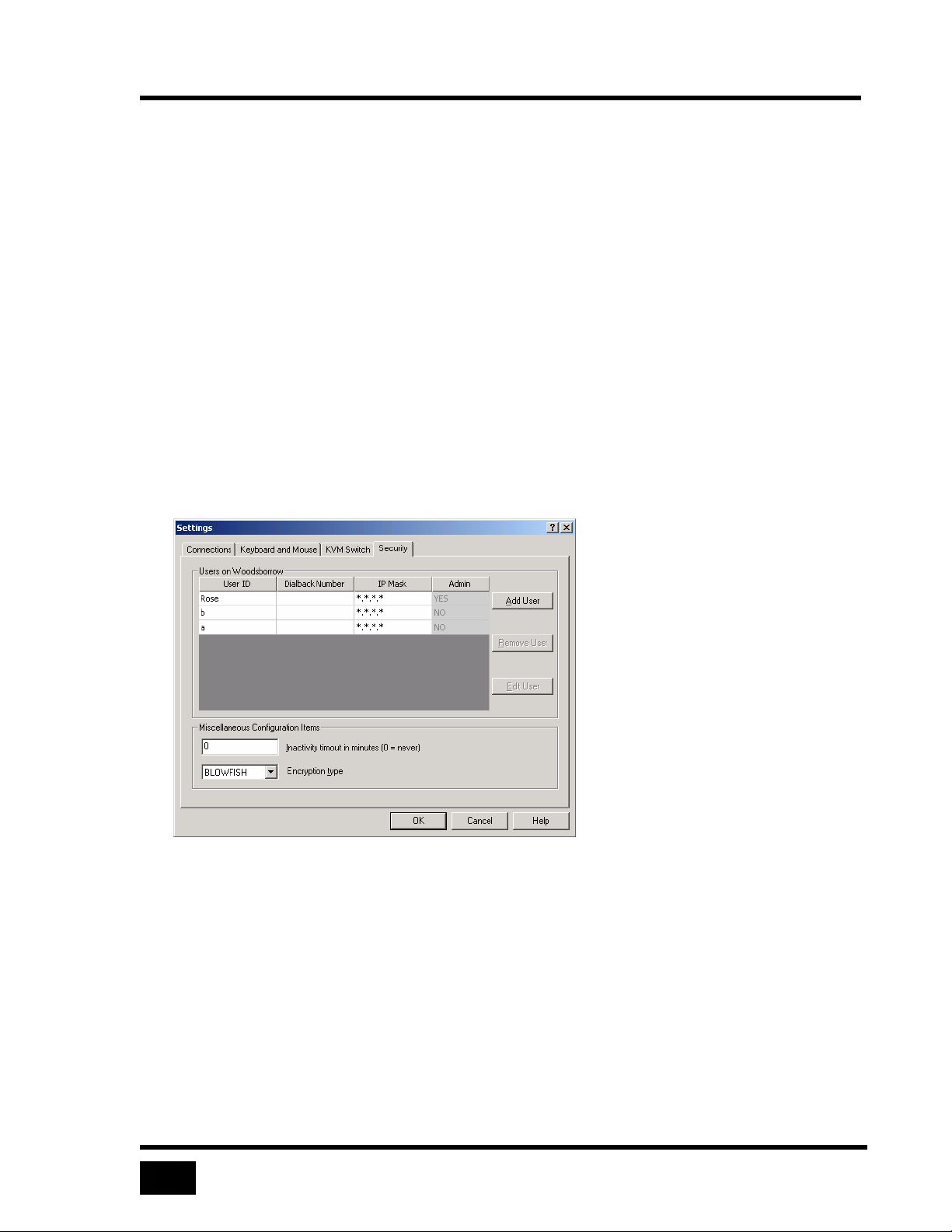
The Security tab displays a list of user accounts on the UltraLink. The administrator
account is the first account, on the top row of the user account list. Also displayed
are inactivity timeout and encryption type fields.
The Add User and Edit User buttons bring up a User Details dialog. Adding a new
user account is similar to editing an existing user account, the only difference is that
the user ID field is empty. Delete a user account by selecting an account from the
user account list and selecting the Remove User button.
Select OK at the bottom of the Security dialog to update user accounts, inactivity
timeout and encryption type on the UltraLink. New settings become active at the
next login. Abandon changes by selecting the Cancel button.
User Settings Table
The user settings table displays a list of users who can log on to the UltraLink and
some of the attributes of the user account, such as user ID, IP mask and Admin. The
Admin field indicates whether the account is an administrator account. There may
only be one administrator account on an UltraLink and is defined when the UltraLink
first starts.
Changes to the user settings table are made using a User Details dialog.
Add User
The Add User button creates a new user account using the User Details dialog. The
new user account is selected in the table. New users are not administrators.
Remove User
The Remove User button deletes a selected user from the user settings table.
Edit User
The Edit User button allows you to change attributes of a selected user using the
User Details dialog. A changed user is selected in the table.
Inactivity Timeout
The UltraLink may disconnect an inactive Viewer to prevent unauthorized access to
the UltraLink and to become available to other Viewers. Inactivity timeout defines
Page 54
Configuration Settings
36
the period of time the UltraLink will monitor a Viewer for keyboard and mouse
events in pass-through mode.
Inactivity timeout is specified in minutes. A value of zero minutes prevents the
session from being disconnected. Any other value disconnects the user if the Viewer
detects no keyboard activity and no mouse movement during the period. The default
period is 30 minutes.
Encryption Type
The Encryption Type field determines whether the data sent between the Viewer and
the UltraLink are encrypted, and if so, which encryption algorithm is used. The
Encryption Type can be one of the following values:
• None
• Triple DES
• Blowfish
Figure 25 Settings dialog
User Details Dialog
User ID
Enter a User ID not already been assigned to another user. The User ID is casesensitive and may not be more than 16 characters long. If you are editing a user
account, the User ID field contains the selected User ID. It is empty if you are
creating a new user account. The Viewer disables the OK button until you enter
a unique User ID and displays a message below the field if the User ID is
invalid. (Maximum number of users = 128)
Page 55
Configuration Settings
37
Password and Confirm Password
As a security measure, these fields do not display what you type. Enter a
password for this account twice, once in the Password field and once in the
Confirm field. This verifies that you entered the password correctly. The
password is case-sensitive and may not be more than 16 characters long. The
Viewer disables the OK button and displays a warning if the password fields do
not match.
Dialback Number
Dialback number is reserved for future use.
IP Mask
The IP Mask field is an optional field that specifies a TCP/IP address or address
range from which the UltraLink may accept connections. When a user logs in,
the UltraLink verifies that the IP address falls within the range defined in the
mask. If it does not, the UltraLink breaks the connection, preventing
unauthorized logins – even with stolen usernames and passwords.
The mask has a fixed dotted-quad format. A fixed address mask is composed
entirely of numbers, for example, 192.168.1.123. A range is specified when any
quad has an asterisk. For example, a mask of 192.168.0.* allows the user to
login from any IP address in the range 192.168.0.1 through 192.168.0.254.
To change the mask, enter mask quads in the IP Mask field. A quad may have a
value in the range of 0 to 255, or may be an asterisk. Enter the IP range of
addresses to which the Viewer may connect in the form nnn.nnn.nnn.nnn. By
default, IP Mask has a value of *.*.*.*, indicating that this account can log in
over TCP/IP connections from any IP address.
OK
When you edit a user account, the Viewer disables the OK button on the
Security tab until you select OK or Cancel on the User Details dialog. Selecting
OK on the User Details button does not save your changes to the UltraLink until
you select the OK button on the Security tab.
Cancel
Abandon changes to User Details by selecting the Cancel button on the User
Details dialog.
Page 56
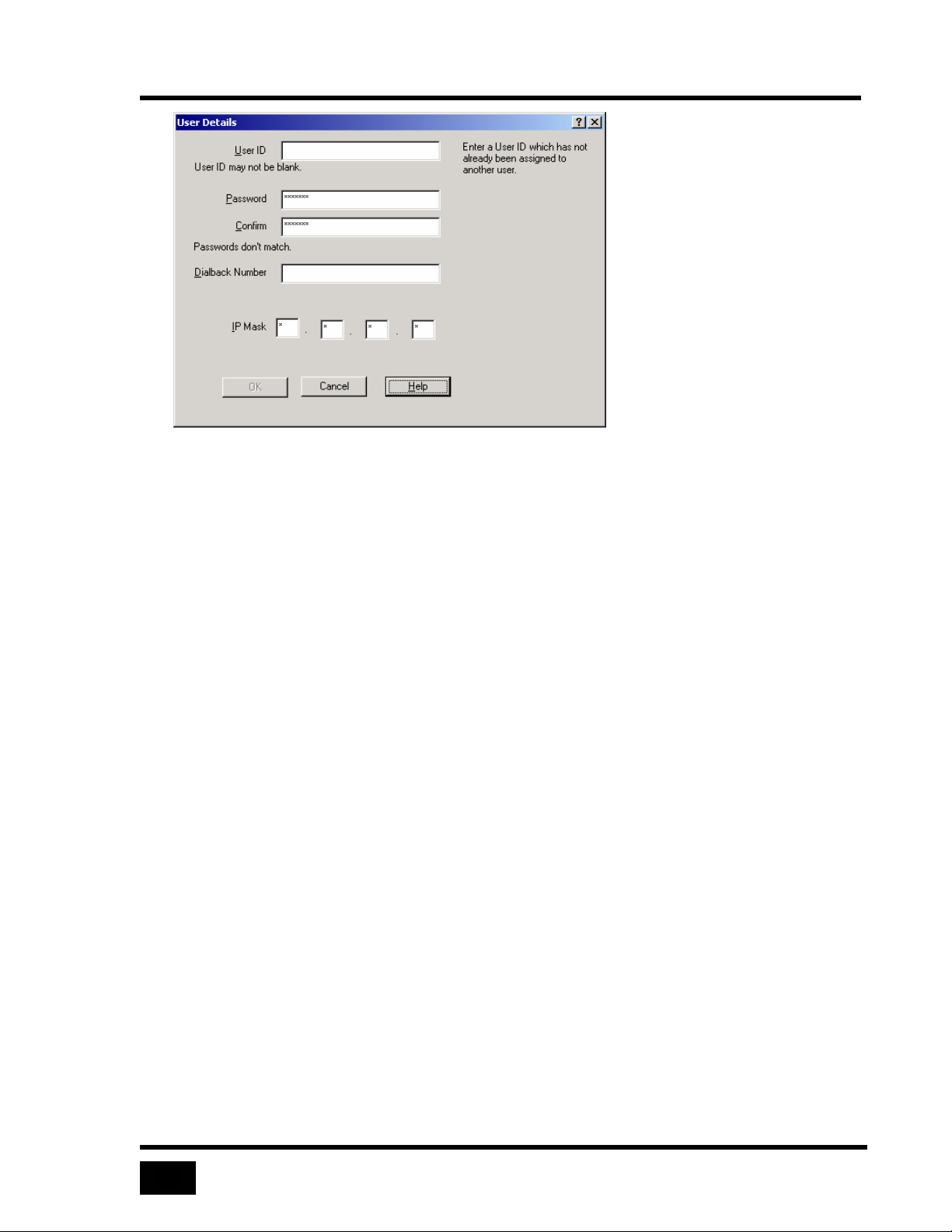
Configuration Settings
38
Figure 26 User Details
Page 57
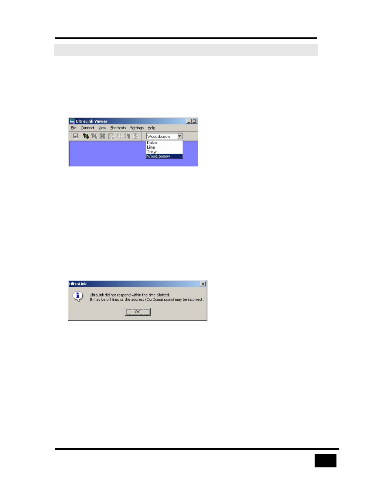
Connecting and Logging In
39
Connecting and Logging In
Connecting
There are two methods of connecting to an UltraLink, the connect menu and the
toolbar. The toolbar button connects to the UltraLink selected in the select list on the
toolbar with a single click.
Figure 27 Choosing an UltraLink to connect
The connection may not complete for one of the following reasons:
• UltraLink is busy with a local user or another Viewer
• UltraLink address is incorrect
• UltraLink is powered off
• Network is not available
• Another login occurs at the same time
In these cases, the Viewer presents the user with an appropriate message.
Figure 28 Cannot find UltraLink
Login
Once connected, the Viewer prompts for a valid user ID and password. If the time to
respond to a login exceeds a limit, the UltraLink displays a message and disconnects.
An UltraLink allows three login attempts before disconnecting. If a valid user ID and
password are not entered in three attempts, the UltraLink terminates the connection
and the Viewer displays a message.
Page 58
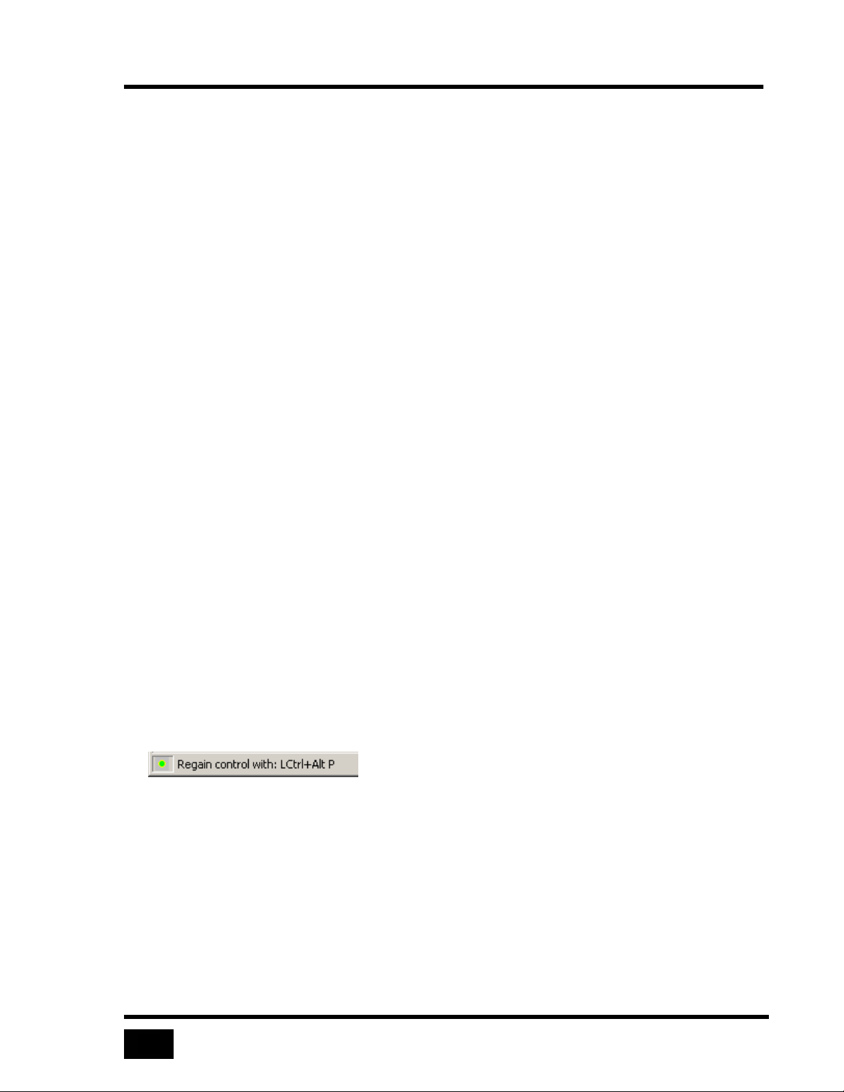
Connecting and Logging In
40
After a successful login:
• The Connect menu changes to Disconnect
• The Connect button on the toolbar is disabled
• The Viewer display area, which previously displayed the message “Not
Connected”, displays video from the remote computer
• The status bar reflect the connection status and the time the Viewer has been
connected to the UltraLink
• The Viewer enters pass-through mode.
Pass-through Mode
After login, the Viewer switches to pass-through mode. Your mouse is restricted to
the display area of the Viewer. Your keyboard and mouse control the remote
computer, but have no effect on your computer. However, by default, pass-through
mode passes all
system keys to your computer.
The
status bar displays the current pass-through status. A green indicator on the
lower left turns on in pass-through mode and turns off when pass-through mode is
exited.
Exiting Pass-through Mode
Since the Viewer’s menus and toolbar are unavailable in pass-through mode, a series
of reserved keystrokes and mouse escape movements regain control of your
computer. The escape method is configurable:
Hotkey shortcut
•
•
Fast mouse escape movement
•
Slow mouse escape movement
Figure 29 The green pass-through indicator
When you enter pass-through mode, the escape method appears on the status bar.
This message on the status bar is not permanent, and subsequent messages may erase
it.
Page 59
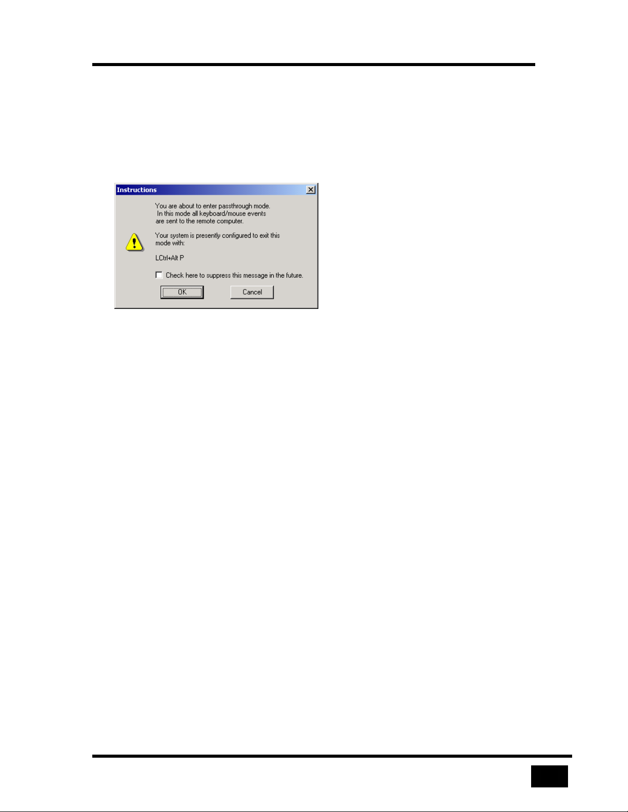
Connecting and Logging In
41
Pass-through Warning Dialog
The Viewer displays a warning dialog before switching into pass-through mode to
remind you of the escape methods. You may disable the warning dialog by checking
the suppress checkbox. With the warning dialog disabled, the Viewer enters passthrough mode after login. Reinstate the warning dialog by checking Pass-through
Warning on the Help menu.
Figure 30 Remember your exit
Reentering Pass-through Mode
After you exit pass-through mode, reenter pass-through by:
• Clicking anywhere in the display area
• Clicking the Pass-through menu option in the View menu
• Use a the key sequence (Ctrl+Alt+P by default) defined in the Keyboard and
Mouse tab of the Settings menu
System Keys
The system keys are as:
• Alt + Tab
• Alt + Esc
• Ctrl + Esc
• The Windows keys
When system keys are local, it is still possible to send Alt + Tab and Ctrl + Alt + Del
to the remote computer without exiting pass-through mode, by using special
keystrokes.
Page 60
Connecting and Logging In
42
Ctrl + Alt + Del and Ctrl + Tab
To send Ctrl + Alt + Del and Alt + Tab to a remote computer without entering passthrough mode use the reboot toolbar button or key combinations. The default key
combinations Ctrl + Alt + T and Ctrl + Alt + A may be modified.
Disconnecting
Either the Viewer or the UltraLink may break a connection. Normally, the Viewer
disconnects when you:
• Select the Disconnect toolbar button
• Select Disconnect on the Connect menu
• Exit the Viewer
The Viewer performs the following functions after a disconnection:
• Displays a message explaining the reason for the disconnect
• Exits pass-through and/or full-screen modes
• Shows the Not Connected blue screen in the display area
• Removes the remote computer select box from the toolbar
• Reverts the Status bar to its unconnected state
• Disables the Disconnect button and menu
The UltraLink disconnects when a local operator performs a Connect or Configure
login or an administrator updates UltraLink firmware.
Page 61
View Modes
43
View Modes
The viewer has modes to show each computer at its clearest possible size, or to lock
the viewer’s size and fit each new image within a selected view size. Select View
modes on the
• If you want to focus on a remote computer, full-screen mode uses 100% of the
monitor to give a feel like being at the remote computer.
• Your computer may have a monitor set to 1280 x 1024 pixels and a remote
computer set to 640 x 480 pixels. In this case, a windowed mode displays the
remote computer, leaving other programs on the desktop visible.
• To monitor a computer’s actions using the minimum possible screen real-
estate, use one of two methods: scale the image down to fit in a small window,
or use scroll bars to view an area of interest, leaving the image at its native
resolution and easier to read.
• Monitor several computers continuously using quad screen mode.
View menu.
• To monitor several computers sequentially, have a KVM switch scan through
its ports continuously.
Scaled and Scrolled
View remote computers in either scaled or scrolled view mode using the View menu.
In scaled view, the Viewer sizes the video image sizes to fit within the display area.
To scale an image, adjust the size of the Viewer window by dragging one or both
edges. Scaling may improve response time on a slow connection, by scaling the
image smaller than the original size.
It may be preferable to scale images to a smaller size but not to a larger size. This is
particularly true when switching between computers using a KVM switch. Enable
the Don’t Enlarge sub-option of Scaled in the View menu. The Viewer displays
scaled-down images when the image is larger than the display area but centers an
image at its native size when the image is smaller than the display area.
In scrolled view, the image from the remote computer is in its native size, providing
the sharpest possible image. If the display area is not large enough to display an
image in either the horizontal or the vertical direction, the Viewer adds scroll bars.
Use the scroll bars to view any part of the image. If the view area is larger than the
remote computer image, the Viewer centers the image in the display area. You may
select scrolled view using the Scrolled menu option of the View menu.
Page 62
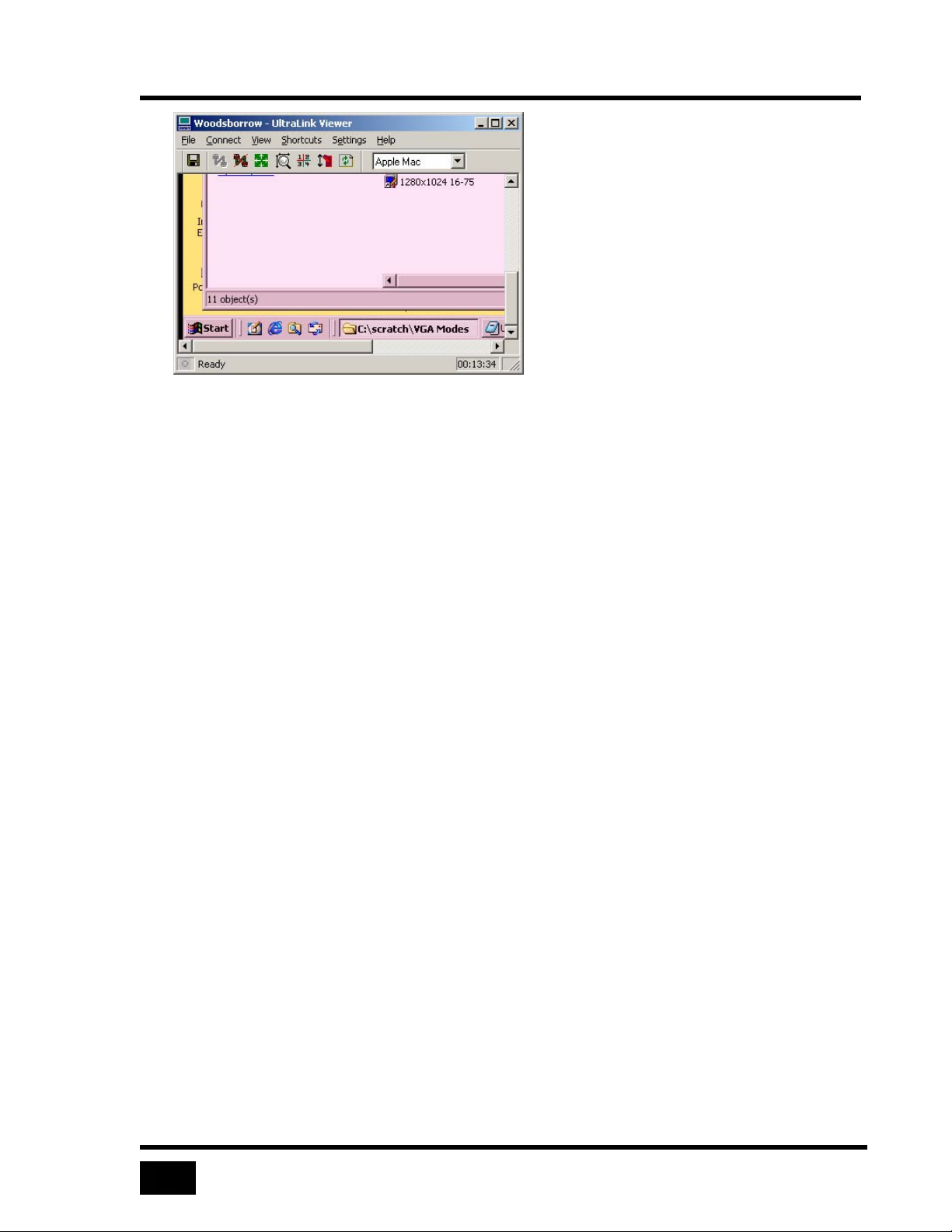
View Modes
44
Figure 31 Scroll bars allow native resolution in a small window
Auto Size
This setting determines what happens when there is a change in a remote computer’s
resolution. This change may occur when switching between ports on a KVM or it
may change several times when a remote computer reboots.
With Auto size off, the Viewer never changes its window size in response to changes
in the incoming resolution. In scaled mode, the Viewer scales the new image to fit
the display area; otherwise, it displays the image with scroll bars or is centered.
With Auto size on, the Viewer resizes after each change in image size. When
possible it sets the image to its native size and fits the Viewer to match the image.
Invoke this command with a button on the toolbar, or select the Auto Size item on
the View menu. The Auto Size command is not available when the Viewer is in
quad-screen or full-screen view. The image below shows how the Viewer looks after
being Auto Sized to fit a 640 x 480 image.
Page 63
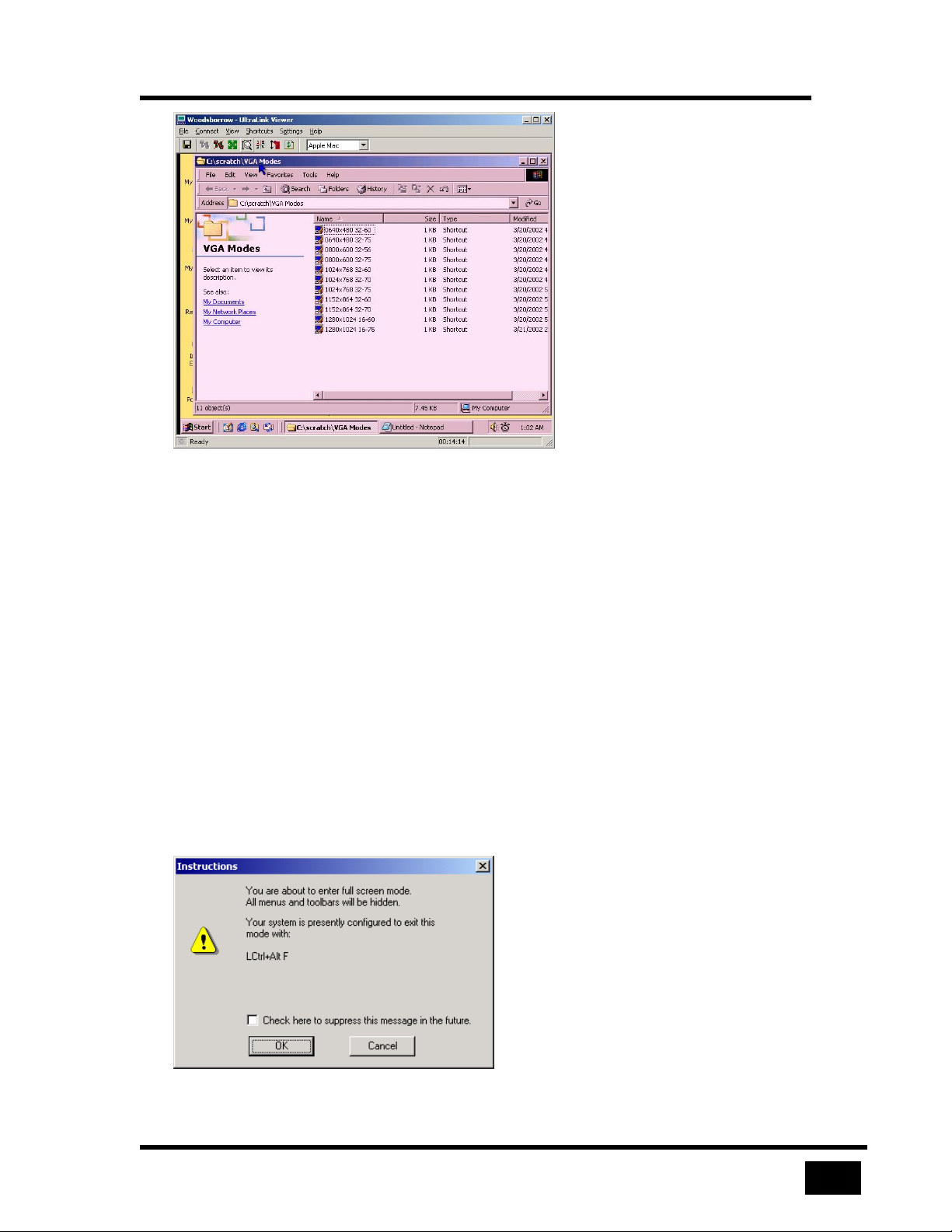
45
Figure 32 Auto Size fits image exactly into the display area
Full-screen
View Modes
In full-screen view, the display area takes over the entire screen of your monitor. The
title bar, menus, toolbar and status bar of the Viewer do not display – only the video
image of the remote computer is visible on the screen.
To enter full-screen view, select the full-screen toolbar button or the full-screen
menu option on the View menu. The Viewer disables full-screen view until you
login to an UltraLink.
A warning dialog displays on entering full-screen view. The dialog gives a brief
description of full-screen view and a means of exiting. The checkbox at the bottom
of the full-screen warning dialog allows suppressing the display of the dialog. If it is
checked, the dialog will not display thereafter when you select full-screen view. If
you suppress the dialog, you may re-enable it by checking the Full Screen Warning
command on the Help menu.
Figure 33 Full-screen warning may be suppressed or reinstated
Page 64
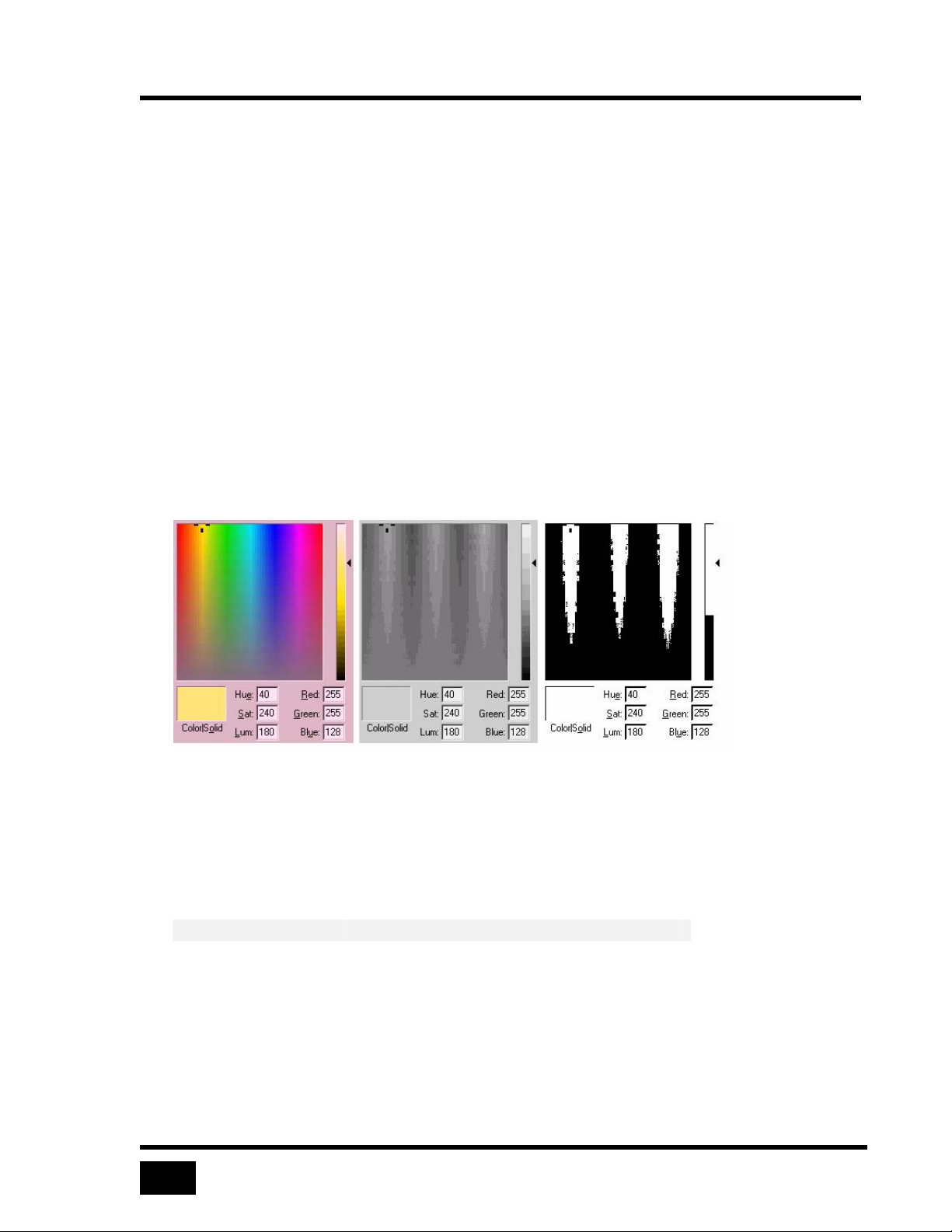
View Modes
46
The Viewer automatically enters pass-through mode when going to full-screen view,
unless the Viewer is in quad-screen view.
In the absence of menus and toolbars in full-screen view, the only way to exit fullscreen view is to use hotkeys or mouse escape movements. Exiting pass-through
mode causes the Viewer to exit full-screen view and return to windowed view. If the
UltraLink disconnects while the Viewer is in full-screen mode, the Viewer returns to
windowed view.
Color Modes
Color modes define how the UltraLink transmits video data to the Viewer. These
modes balance color resolution against transmission speed. Color Modes are set on
View menu. The currently active color mode appears as a dot to the left on the
the
View menu.
The following figure shows typical examples of how each mode looks and the table
gives an approximation of the tradeoffs.
Figure 34 Color affects image quality
These characterizations are approximate; actual results depend on the nature of the
screens. If the images are mostly solid colors, reducing the color quality will have
little effect on the transmission speed. If the images contain gradients or complex
graphics, the speed increase may be dramatic.
Mode Image Quality Speed
Color High Low
Grey Medium Medium
Black and White Low High
Table 4 Color mode affects image quality and speed
Page 65
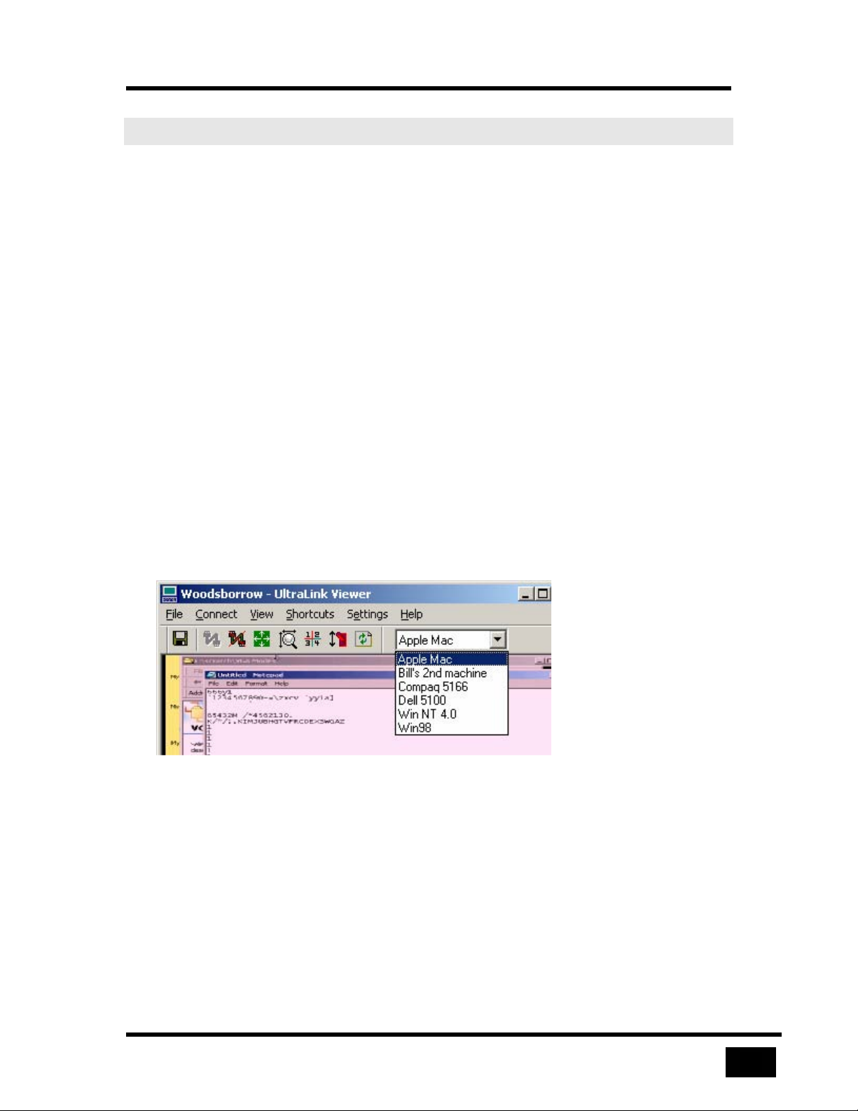
Using a KVM Switch
47
Using a KVM Switch
KVM Switch Features
Enable KVM switch features by selecting a KVM switch type in the device list of the
KVM Switch tab of the Settings menu. Then save the switch settings to the
UltraLink by selecting OK at the bottom of the Settings dialog.
Using an UltraLink with a KVM switch enables the following features:
•
Remote computer select
Quad-screen
•
•
Switch file import and export
Remote Computer Select
When you enable KVM switch features, a remote computer select box appears on the
toolbar after login. Selecting a name in the remote computer select box immediately
connects your keyboard, mouse, and video to that computer’s port on the switch. The
Viewer saves the name you select in the remote computer select list and displays it
the next time you login.
Figure 35 Switch to a remote computer by name
If you select a remote computer at a different screen resolution than one you are
viewing, the screen resolution description on the status bar updates.
Page 66
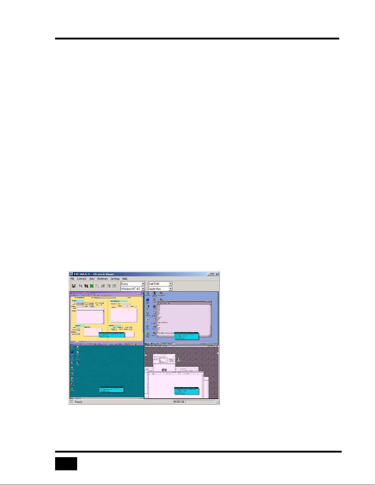
Using a KVM Switch
48
Quad Screen
In quad-screen view, the Viewer displays video from up to four remote computers by
controlling the KVM switch to change ports. Keystroke events to cause the KVM
switch to select a computer port are defined using the
Settings menu.
You may toggle between single-screen view and quad-screen view by clicking the:
• Single or Quad commands of the View menu
• Quad Screen toggle button on the toolbar
When you select quad-screen view for the first time, your screen remains the same,
except that the toolbar shows four remote computer select lists, one for each
quadrant. The position of the select box corresponds to a quadrant. Once you select
more than one computer in the select boxes, the Viewer divides its display area into
four quadrants. All the quadrants are always the same size and each video image
scales to fit into a quadrant. The Viewer save the names you select in the remote
computers select boxes and displays them the next time you select quad-screen view.
KVM Switch tab of the
Quad-screen view is a view only mode – mouse and keyboard do not control any of
the four remote computers and the Viewer does not enable pass-through mode.
You may select full-screen view while in quad-screen view; however, you may not
switch remote computers in the quadrants because the toolbar and the remote
computer select lists are not visible.
Figure 36 Select a quadrant’s image using the corresponding computer select list
Page 67
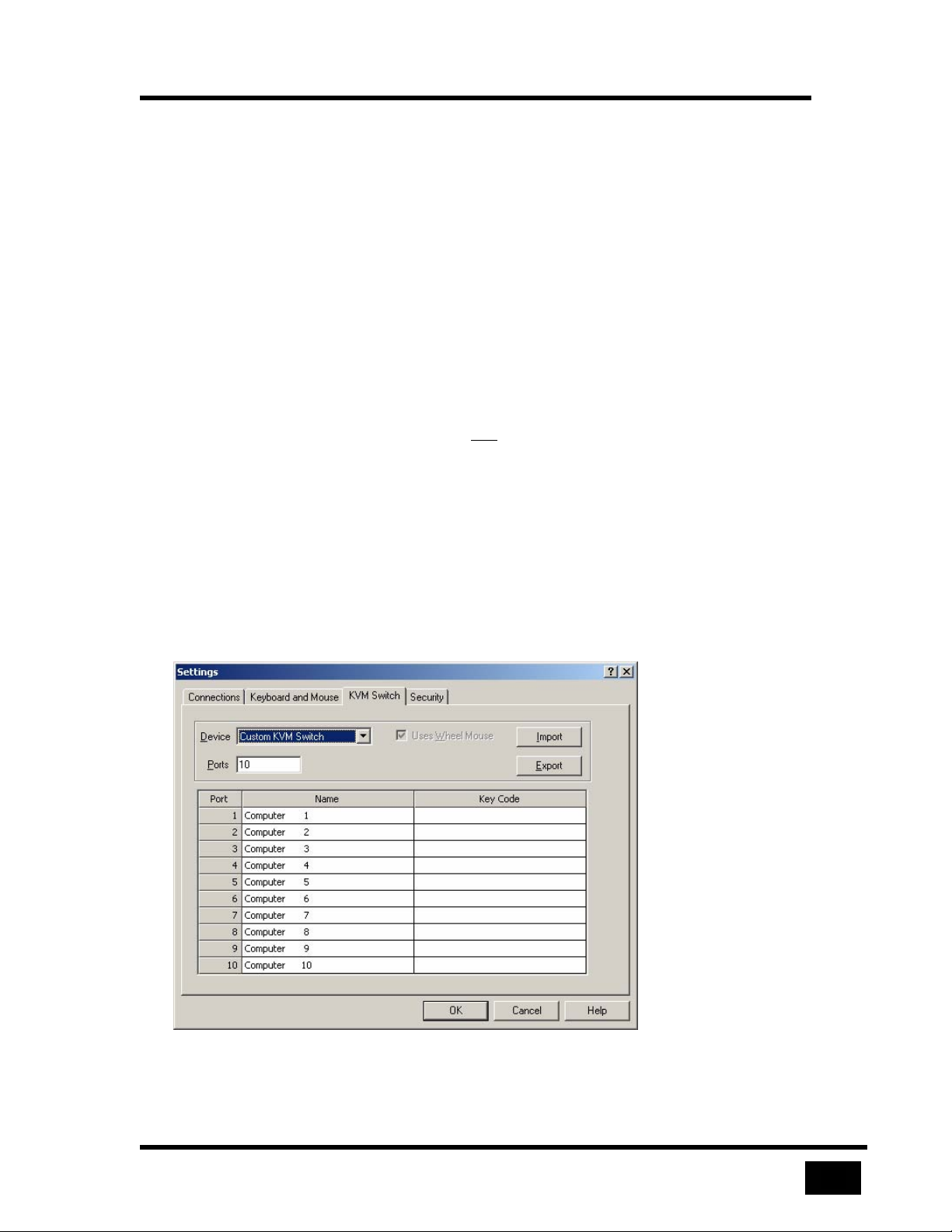
Using a KVM Switch
49
Switch File Import and Export
The Key Code column on the KVM Switch tab of the Settings menu defines
keyboard events to make a KVM switch select a port. Key Code is automatically
defined in for KVM devices defined in the Device list box.
A custom KVM switch requires you to specify the key codes. To enter key codes,
enter the text on the keyboard’s key tops with the following exceptions:
• Remove spaces from keys that use two words, e.g. PrintScreen
• Tab is Tab
• Ctrl, Shift, and Alt are designated left or right by a preceding L or R, e.g.
LCtrl or RShift
• Keys normally represent a down and
strokes separately by adding -up or –dn, e.g. LCtrl-dn H LCtrl-up
• Precede keypad keys with KP, e.g. KP8
• Arrow keys are spelled: Larrow, Rarrow, Uarrow, DArrow
• The key is spelled: BackSpace
The Viewer validates keystrokes. If there are invalid keystrokes, a message dialog
indicates the problem found and summarize the rules for entering keystrokes.
an up stroke. Designate down and up
Figure 37 Key codes are editable for custom switches
Page 68
Using a KVM Switch
50
Switch File Content Rules
Use the Import and Export buttons to save and retrieve switch settings to text files,
which you may edit with any text editor. To create a switch file use the example
below.
Line Content Notes
1
custom
2
3
4
5
``Exit Sequence`LCtrl L
6
`1`Computer 1`LCtrl 1 Enter
7
`2`Computer 2`LCtrl 2 Enter
8
`3`Computer 3`LCtrl 3 Enter
9
Blank, reserved for future use
Switch type
Blank, reserved for future
use
Blank, reserved for future
use
Blank, reserved for future
use
Specifies an exit sequence
Port #, name, keystrokes
Port #, name, keystrokes
Port #, name, keystrokes
Table 5 Switch file contents
Switch type must be present and may be on any of the first five lines. The switch
should be custom. Starting with line 6, each line must have three grave accent “ ` ”
delimiters with the data arranged as follows:
• Delimiter
• Port number
• Delimiter
• Computer name
• Delimiter
• Key code
Page 69
51
Safety
This UltraLink Unit has been tested for conformance to safety regulations and requirements,
and has been certified for international use. Like all electronic equipment, the UltraLink
Unit should be used with care. To protect yourself from possible injury and to minimize the
risk of damage to this Unit, read and follow these safety instructions.
Caution! Risk of explosion can occur if the battery is replaced with an
incorrect type. Dispose of used batteries according to the manufacturer’s
instructions.
Follow all instructions and warnings marked on this Unit.
Except where explained in this manual, do not attempt to service this Unit
yourself.
Do not use this Unit near water.
Assure that the placement of this Unit is on a stable surface or rack mounted.
Provide proper ventilation and air circulation.
Keep power cord and connection cables clear of obstructions that might cause
damage to them.
Use only power cords, power transformer and connection cables designed for
this Unit.
Use only a grounded (three-wire) electrical outlet.
Keep objects that might damage this Unit and liquids that may spill, clear from
this Unit. Liquids and foreign objects might come in contact with voltage points
that could create a risk of fire or electrical shock.
Operate this Unit only when the cover is in place.
Do not use liquid or aerosol cleaners to clean this Unit. Always unplug this Unit
from its electrical outlet before cleaning.
Unplug this Unit from the electrical outlet and refer servicing to a qualified service
center if any of the following conditions occur:
The power cord or connection cables is damaged or frayed.
The Unit has been exposed to any liquids.
The Unit does not operate normally when all operating instructions have
been followed.
The Unit has been dropped or the case has been damaged.
The Unit exhibits a distinct change in performance, indicating a need for
service.
Page 70
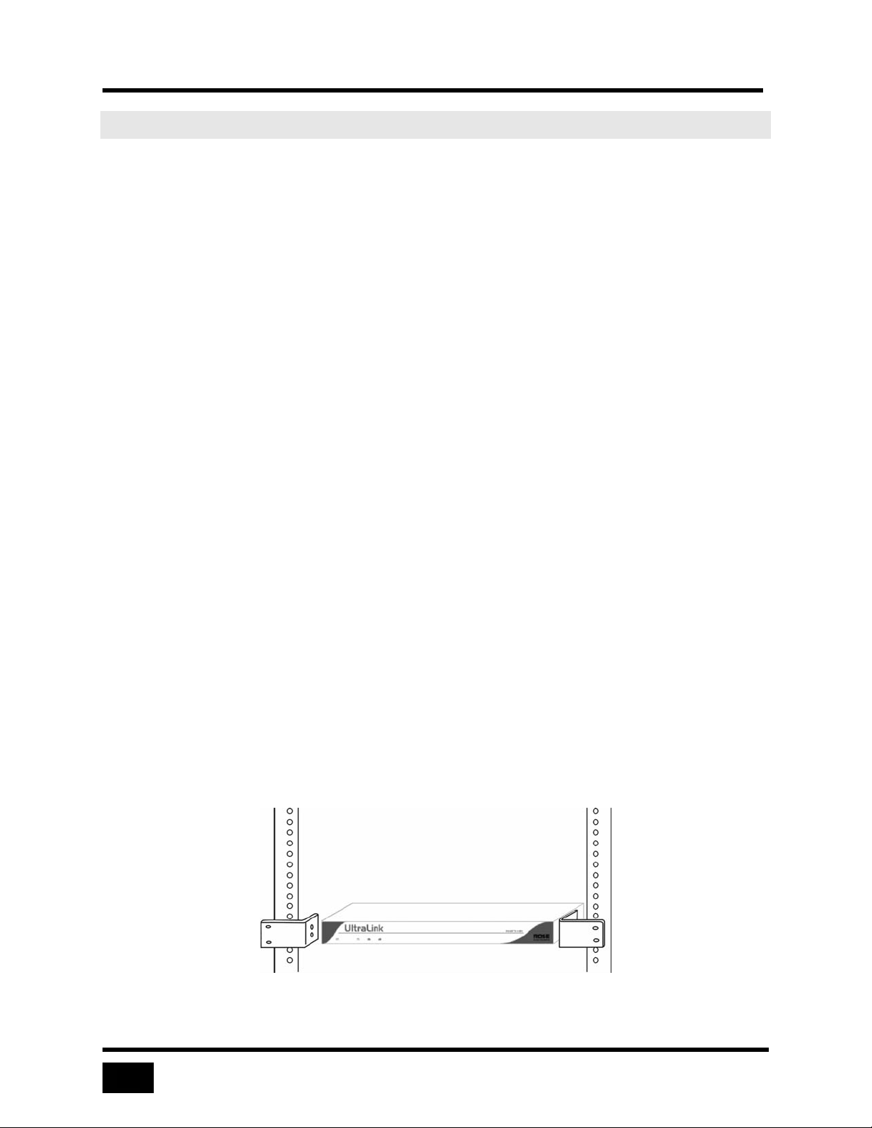
Appendix A. Rack mount
52
Appendix A. Rack mount
The rack mount kit includes the following items:
Two black anodized mounting brackets.
Four 6 - 32 x 3/8” flat head mounting screws.
To rack mount your UltraLink unit, attach the two rack mounting brackets to your Unit
with the short flange against the Unit using the four screws provided. Secure the
mounting brackets to the rack using the appropriate size bolts, nuts and lock washers.
Using hardware other than that provided could cause damage to the electronics and/or
result in loss of mounting integrity. Do not over tighten the screws used to mount the
Unit to the mounting brackets.
The following general guidelines should be observed when installing your Unit into a
rack.
a). The UltraLink is designed to work in an ambient temperature of 0
b). Do not block power supply vents or otherwise restrict airflow when rack-
c). Mechanical loading of the rack should be considered to prevent instability and
d). Tighten all connectors securely and provide adequate strain relief for all
e). Provide a grounded power source to all Units. Pay special attention to overall
ο
F – 113ο F).
(32
mounting this Unit.
possible tipping over.
cables.
branch circuit load ratings before connecting equipment to this source.
Overloaded circuits are potential fire hazards and can cause equipment
failures or poor performance.
ο
C to 45ο C
Rack mount illustration
Page 71
53
Index
A
Administrator
account, 35
configures KVM switch features, 25
configures security, 25, 35
default account, 9
Auto size, 44
B
Back panel, 5
C
Color modes, 46
Configuration
Connections, 28
Encryption, 35
Inactivity timeout, 35
Keyboard and mouse, 30
KVM switch, 33
Security, 35
UltraLink, 11
Users, 35
Configuration
Gateway, 11
Subnet mask, 11
TCP/IP, 11
Configuring the UltraLink and Viewer, 24
Connect, 20
Connect failure, 39
Connectors, 5
D
H
Help options, 26
Hotkeys, 30
I
Inactivity timeout, 35
K
Keystrokes to control KVM switch, how to enter
them, 49
KVM
device, 33
KVM features
Quad-screen, 47
Remote computer select, 47
Switch file import and export, 47
L
Local mode, 12
M
Menus
Connect, 20
File, 19
Help, 26
Settings, 24
Shortcuts, 23
View, 20
Mouse escape movements, 31
Fast mouse, 31
Slow mouse, 31
Disconnect, 20, 42
Encryption type, 35, 36
Exiting the program, 19
Flash update, 19
Front panel, 5
Full-screen view, 45
E
F
P
Pass-through mode, 40
Password defeat jumper, 12
Power on, 8
Q
Quad-screen view, 22, 48
S
Saving a bitmap of the screen, 19
Scaled view, 43
Page 72
Index
54
Scrolled view, 43
System keys, 24, 41
T
Timeout, 35
Toolbar, 15
selecting remote computer from, 47
U
UltraLink login
configure, 9
connect, 9
UltraLink Viewer
Requirements, 13
Setup Wizard, 13
User accounts, 35
V
View commands
Auto size now, 22
Full-screen, 23
Pass-refresh, 23
Pass-through, 23
Status bar, 22
Toolbar, 22
View modes, 43
Auto size, 21, 44
Black and white, 22
Color, 22, 46
Don’t enlarge, 21
Full-screen, 45
Gray, 22
Quad-screen, 22
Scaled, 21
Scrolled, 21
Single, 22
Viewing multiple remote computers at once, 22,
48
W
Warnings
Full-screen, 26
Pass-through, 26, 41
Page 73

Page 74

10707 Stancliff Road Phone (281) 933-7673
Houston, Texas 77099 Internet: WWW.ROSE.COM
 Loading...