

Page 1
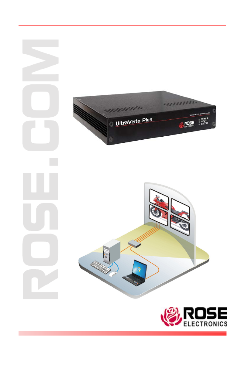
UltraVista Plus VIDEO WALL CONTROLLER
10707 Stancliff Road
Houston, Texas 77099
800-333-9343
www.rose.com
Manual
P/N VWL-D122DDL
Installation and Operations
Page 2

Page 3

LIMITED WARRANTY
Rose Electronics® warrants the UltraVista™ Plus to be in good working order for one year from
the date of purchase from Rose Electronics or an authorized dealer. Should this product fail to
be in good working order at any time during this one-year warranty period, Rose Electronics
will, at its option, repair or replace the Unit as set forth below. Repair parts and replacement
units will be either reconditioned or new. All replaced parts become the property of Rose
Electronics. This limited warranty does not include service to repair damage to the Unit
resulting from accident, disaster, abuse, or unauthorized modification of the Unit, including
static discharge and power surges.
Limited Warranty service may be obtained by delivering this unit during the one-year warranty
period to Rose Electronics or an authorized repair center providing a proof of purchase date. If
this Unit is delivered by mail, you agree to insure the Unit or assume the risk of loss or damage
in transit, to prepay shipping charges to the warranty service location, and to use the original
shipping container or its equivalent. You must call for a return authorization number first. Under
no circumstances will a unit be accepted without a return authorization number. Contact an
authorized repair center or Rose Electronics for further information.
ALL EXPRESS AND IMPLIED WARRANTIES FOR THIS P RO DUCT INCLUDING THE
WARRANTIES OF MERCHANTABILITY AND FITNESS FOR A PARTICULAR PURPOSE,
ARE LIMITED IN DURATION TO A PERIOD OF ONE YEAR FROM THE DATE OF
PURCHASE, AND NO WARRANTIES, WHETHER EXPRESS OR IMPLIED, WILL APPLY
AFTER THIS PERIOD. SOME STATES DO NOT ALLOW LIMITATIONS ON HOW LONG AN
IMPLIED WARRANTY LASTS, SO THE ABOVE LIMITAT IO N MAY NOT APPLY TO YOU.
IF THIS PRODUCT IS NOT IN GOOD WORKING ORDER AS WARRANTIED ABOVE, YOUR
SOLE REMEDY SHALL BE REPLACEMENT OR REPAIR AS PROVIDED ABOVE. IN NO
EVENT WILL ROSE ELECTRONICS BE LIABLE TO YOU FOR ANY DAMAGES INCLUDING
ANY LOST PROFITS, LOST SAVINGS OR OTHER INCIDENTAL OR CONSEQUENTIAL
DAMAGES ARISING OUT OF THE USE OF OR THE INABILITY TO USE SUCH PRODUCT,
EVEN IF ROSE ELECTRONICS OR AN AUTHORIZED DEALER HAS BEE N ADVISE D OF
THE POSSIBILITY OF SUCH DAMAGES, OR FOR ANY CLAIM BY ANY OTHER PARTY.
SOME STATES DO NOT ALLOW THE EXCLUSION OR LIMITATION OF INCIDE NTAL O R
CONSEQUENTIAL DAMAGES FOR CONSUMER PRODUCTS , SO T HE ABO VE MAY NOT
APPLY TO YOU. THIS WARRANTY GIVES YOU SPECIFIC LEGAL RIGHTS AND YOU MAY
ALSO HAVE OTHER RIGHTS WHICH MAY VARY FROM STATE TO STATE.
NOTE: This equipment has been tested and found to comply with the limits for a Class B digital
device, pursuant to Part 15 of the FCC Rules. These limits are designed to provide reasonable
protection against harmful interference when the equipment is operated in a commercial
environment. This equipment generates, uses, and can radiate radio frequency energy and, if
not installed and used in accordance with the instruction manual, may cause harmful
interference to radio communications. Operation of this equipment in a residential area is likely
to cause harmful interference in which case the user will be required to correct the interference
at his own expense.
IBM, AT, and PS/2 are trademarks of International Business Machines Corp. Microsoft and
Microsoft Windows are registered trademarks of Microsoft Corp. Any other trademarks
mentioned in this manual are acknowledged to be the property of the trademark owner.
Copyright Rose Electronics 2012. All rights reserved.
No part of this manual may be reproduced, stored in a retrieval system, or transcribed in any form or any
means, electronic or mechanical, including photocopying and recording, without the prior written permission
of Rose Electronics.
Rose Electronics Part # MAN-UVPlus
Printed In the United States of America – Revision 1.1
Page 4

TABLE of CONTENTS
CONTENTS P AGE #
Disclaimer ....................................................................................................... 1
System Introduction ........................................................................................ 1
Product Registration ....................................................................................... 1
About this manual ........................................................................................... 1
Features ......................................................................................................... 2
Package contents ........................................................................................... 2
Rose Electronics web site .............................................................................. 2
Models ............................................................................................................ 3
Installation ...................................................................................................... 3
Unit Installat io n ........................................................................................... 4
Configuration............................................................................................... 4
Configuring DVI Input resol ution ................................................................. 5
Monitor Outputs .......................................................................................... 5
Selecting the Regions to Be Displayed ...................................................... 6
UltraVista Plu s Co ntr ol Application ................................................................. 7
Application Installation ................................................................................ 7
Connection diagram .................................................................................... 8
Device section............................................................................................. 8
DVI-D Input section ..................................................................................... 9
Figures P AGE #
Figure 1. Models ............................................................................................. 3
Figure 2. Typical Installation ........................................................................... 3
Figure 3. Control Application .......................................................................... 7
Appendix PAGE #
Appendix A - Specifications .......................................................................... 19
Page 5

INTRODUCTION
Disclaimer
While every precaution has been taken in the preparation of this manual, the
manufacturer assumes no responsibility for errors or omissions. Neither
does the manufacturer assume any liability for damages resulting from the
use of the information contained herein. The manufacturer reserves the
right to change the specifications, functions, or circuitry of the product
without notice.
The manufacturer cannot accept liability for damages due to misuse of the
product or other circumstances outside the manufacturer’s control. The
manufacturer will not be responsible for any loss, damage, or injury arising
directly or indirectly from the use of this product.
System Introduction
Thank you for choosing the Rose Electronics UltraVista™ Plus. The
UltraVista Plus is the result of Rose Electronics commitment to providing
state-of-the-art solutions for today’s demanding workplace. The UltraVista
Plus has proven to be a valuable investment for any business or office that
has a need to display, manipulate, and control video on a multiple display
array.
The UltraVista Plus video wall represents the latest in video displaying
technology. The advanced design of the UltraVista Plus can display
standard single-link or dual-link DVI signals from a video source and display
all or a selected area of the input signal across four DVI or analog RGB
monitors. The flexibility of controlling software allows for multiple UltraVista
Plus units to be controlled from a single computer.
Product Registration
Take advantage of the following when you register your Rose Electronics
products online at www.rose.com/htm/warranty.htm:
Rose Standard Warranty Plus...
Free Lifetime Firmware Updates
Free Lifetime Tec hnical Su ppor t
30 Day Money Back Guarantee
Priority “First-in-Line” Status for Tech Support
About this manual
This manual covers the installation and operation of UltraVista Plus.
UltraVista Plus Installation and Operations Manual 1
Page 6

Features
Single or dual link DVI input support
Max output resolution 2048 x 2048
Full bezel width and height correc tion
Splits a single DVI input into four independent outputs
Output monitors can be DVI or Analog RGB
Each output monitor can display any selected area of the input image
Auto-detection of input resolution and output monitor native resolution
Default setting displays ¼ of the input signal on each output monitor in a
2x2 array.
Each output monitor can display any rectangular section of the input
video signal
The graphical utility provides easy configuration for cropping, scaling,
rotating, and gap compensatio n.
Power, status, and input indicators
The firmware detects when the input and output timings are set to
identical frame rates and will automatically genlock the syncs.
Package contents
The package contents consist of the following:
UltraVista main unit
Documentation CD with configuration control software
Power adapter and Power cord
Rackmount kit
Installation and operations manual
If the package contents are not correct, contact Rose Electronics or your
reseller, so the problem can be quickly resolved.
Rose Electronics web site
Visit out web site at www.rose.com for additional information on other
products that are designed for data center applications, classroom
environments and other applications.
2 UltraVista Plus Installation and Operations Manual
Page 7
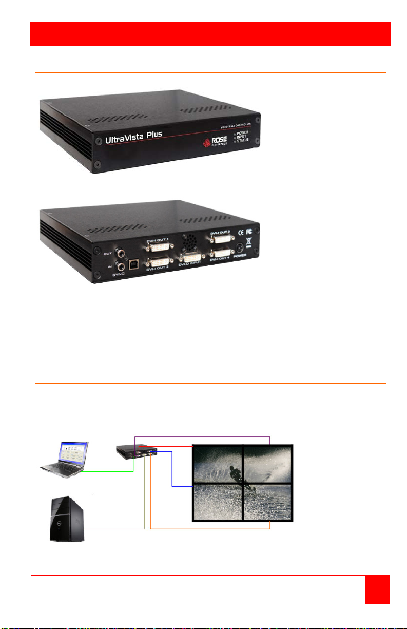
MODELS
Front View
DVI Source
Models
Figure 1. Models
Rear View
Indicators
Power
Input
Status
Connectors
Sync – For future
enhancements
USB – to control
PC via USB A/B
cable (supplied)
Input – DVI-D
Output (4) – DVI-I
Power
Installation
Figure 2 shows a typical installation. Be sure to install the provided USB
drivers on the control computer before connecting it to the UltraVis ta Plus ’s
USB port.
Figure 2. Typical Installation
UltraVista Plus Installation and Operations Manual 3
Page 8

Unit Installation
Installing the UltraVista Plus is a straight forward procedure. First:
Make sure that the power supply for the DVI source is disconnected
Connect a DVI cable from the DVI source to the DVI-D input connector
on the rear panel of the UltraVista Plus
Connect up to four displays to the DVI-I output connectors on the rear
panel
Connect the 5VDC power adapter to the UltraVista Plus power input
jack and apply power to the unit
Last, power up the DVI source
The Power LED on the front panel will illuminate to indicate that power has
successfully been applied to the unit.
The UltraVista Plus has an internal processor that will continuously monitor
the DVI input signal, and the input LED will be illuminated when a valid and
stable input is detected.
If the Input LED is not illuminated, the UltraVista Plus cannot detect a valid
DVI input source.
During operation, the UltraVista Plus is able to adjust its internal operation to
maintain the programmed output proportions even when the input resolution
changes.
Configuration
The UltraVista Plus stores a number of parameters to configure its
operation. This allows it to operate stand alone in a very flexible manner.
The configurations affect the input and output display modes as well as how
the input image is displayed over multiple monitors.
The UltraVista Plus default c onfiguration is:
Input EDID Preferred Mode: 1920 x 1080 x 60Hz (SMPTE timings)
Output monitor mode: Use Monitor Preferred Mode
Default:1920 x 1080 x 60Hz (SMPTE)
Cropping Mode: 2x2 equal split (960x540)
No Rotation, No bezel compensation
These settings can be changed using the provided UltraVista Plus control
application. This is executed from a computer connected to the USB port on
the UltraVista Plus. The application can be run on any Windows® platform
(see the Control Application section for additional information).
4 UltraVista Plus Installation and Operations Manual
Page 9

Configuring DVI Input resolution
Because the timings and resolution of the DVI input are set by the DVI
source machine, the UltraVista Plus can only configure this indirectly by
presenting a programmable “Preferred Mode” as part of its EDID (Extended
Display Identification Dat a).
Most graphics cards and HDMI appliances automatically select the
“Preferred Mode” resolution and timings presented by the UltraV ist a Plus
EDID, but they may need to be forced to re-detect if the EDID contents are
changed by the Ultr a Vis t a Plus application. This would typically be via a hotplug event caused by disconnecting and reconnecting the DVI input cable.
The configuration application will allow read-back of the resolution that is
currently being detected, as well as the ability to read and write the internal
EDID rom.
Monitor Outputs
The UltraVista Plus can be configured to read the corresponding EDID of
each monitor that is connected and to drive out a signal that corresponds to
the resolution, timings and mode (RGB or DVI) of the Preferred Mode. This
is the factory default configuration.
Please note that when different monitors are attached to the four outputs,
each may advertise a different Preferred Mode, therefore each output will be
driven at a different mode.
Whenever the monitor EDID is used, the Ul traV is ta Plus will calculate the
internal scale factors to ensure that the monitor (at whatever resolution it is
being driven) will still display the correct proportion of the input image.
If an EDID cannot be read (for example if the monitor cable does not
support the DDC signals required), there is a default mode that can be
programmed into the U lt r a Vis ta P lus’s memory. This is factory configured to
1920x1080p.
In some cases it may be that the user requires a very specific output timing
(for example when genlocking to the input) irrespective of the monitor
EDIDs. In this case the UltraVista Plus can be configured to always output
the mode that has been programmed as the default mode.
UltraVista Plus Installation and Operations Manual 5
Page 10

Selecting the Regions to Be Displayed
Each output of the UltraVista Plus can take its display data from any
arbitrary rectangular region of the captured input image. The factory default
for these cropping rectangles configures the four monitors to display a
quarter of the input as a 2x2 array, and these proportions are maintained
across different input resolutions.
For a 1080p input, this means that 960x540 pixels from the input image
would be up-scaled by a factor of 2 in each direction if the selected output
resolution was 1080p.
However if the input resolution were to change to 1600x1200, then for the
same output monitor the UltraVista Plus would upscale from an 800x600
region and would reprogram its scale factors to 2.4 horizontally and 1.8
vertically to support the same 1080p monitor.
The cropping regions can be assigned arbitrarily and can overlap, the only
restriction being that the resulting scale factor must be greater than 1.0 (ie
1:1 or up-scaled) in either direction. As an example it is possible to use the
UltraVista Plu s to output four identical copies of the input signal (providing
the resulting output timings remain within the capabilities of the single-link
DVI outputs).
The regions of the input image to be displayed on a given output monitor
can be programmed via USB by using the UltraVista Plus configuration
application.
In order to support portrait orientation of monitors, the source data can be
rotated by 90º, 180º or 270º as it is output to the monitor.
6 UltraVista Plus Installation and Operations Manual
Page 11
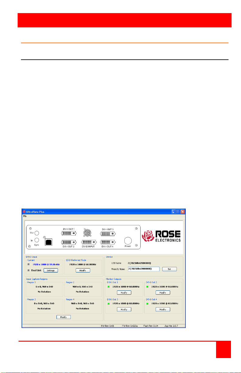
Control Application
UltraVista Plus Control Application
Application Installation
Note: Do not connect the UltraVista Plus to the controlling computer’s USB
port until the driver installation is complete.
Locate the Install folder on the supplied CD, run the install.exe program, and
follow the installation wizar d instructions. During installation a warning
message is displayed stating that the driver does not have Windows® Logo
accreditation. Select Continue Anyway to complete the installation.
The UltraVista Plus can now be connected to a suitable USB 1.0 or 2.0 port
using the cable supplied. At this point the hardware will be detected by
Windows as an Ultr a Vis t a Plus , and a New Hardware wizard is displayed.
Allow the wizard to search, and click on the recommended option to enable
the previously installed driver to be associated with the new hardware.
Press Continue Anyway to accept the driver.
Running the Control Application
To open the Control Application select Start/All Programs/UltraVista
Plus/UltraVista Plus.
The application will search for an UltraVista Plus connected to your
computer and display the status of the first unit detected. If more than one
UltraVista Plu s is connected, a list of all available UltraVis ta Plus’s can be
found in the File menu.
Figure 3. Control Application
UltraVista Plus Installation and Operations Manual 7
Page 12
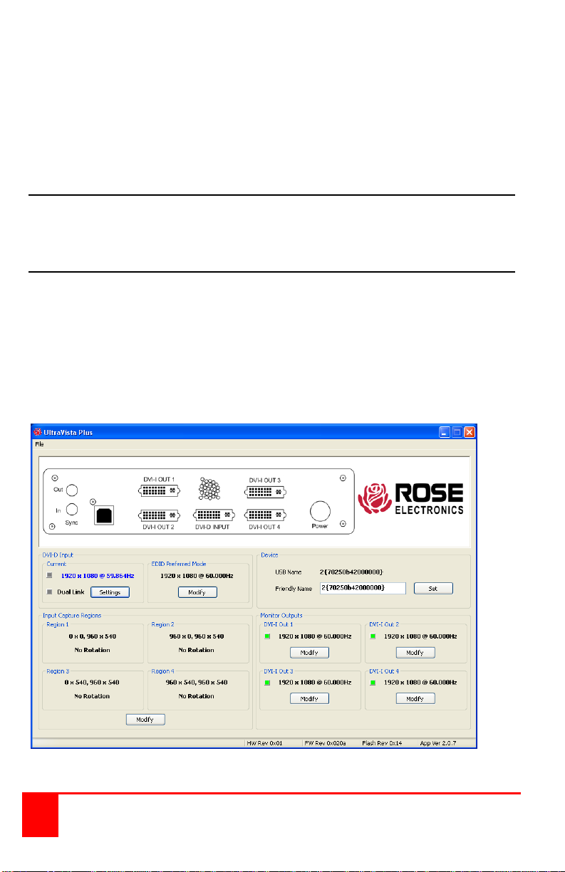
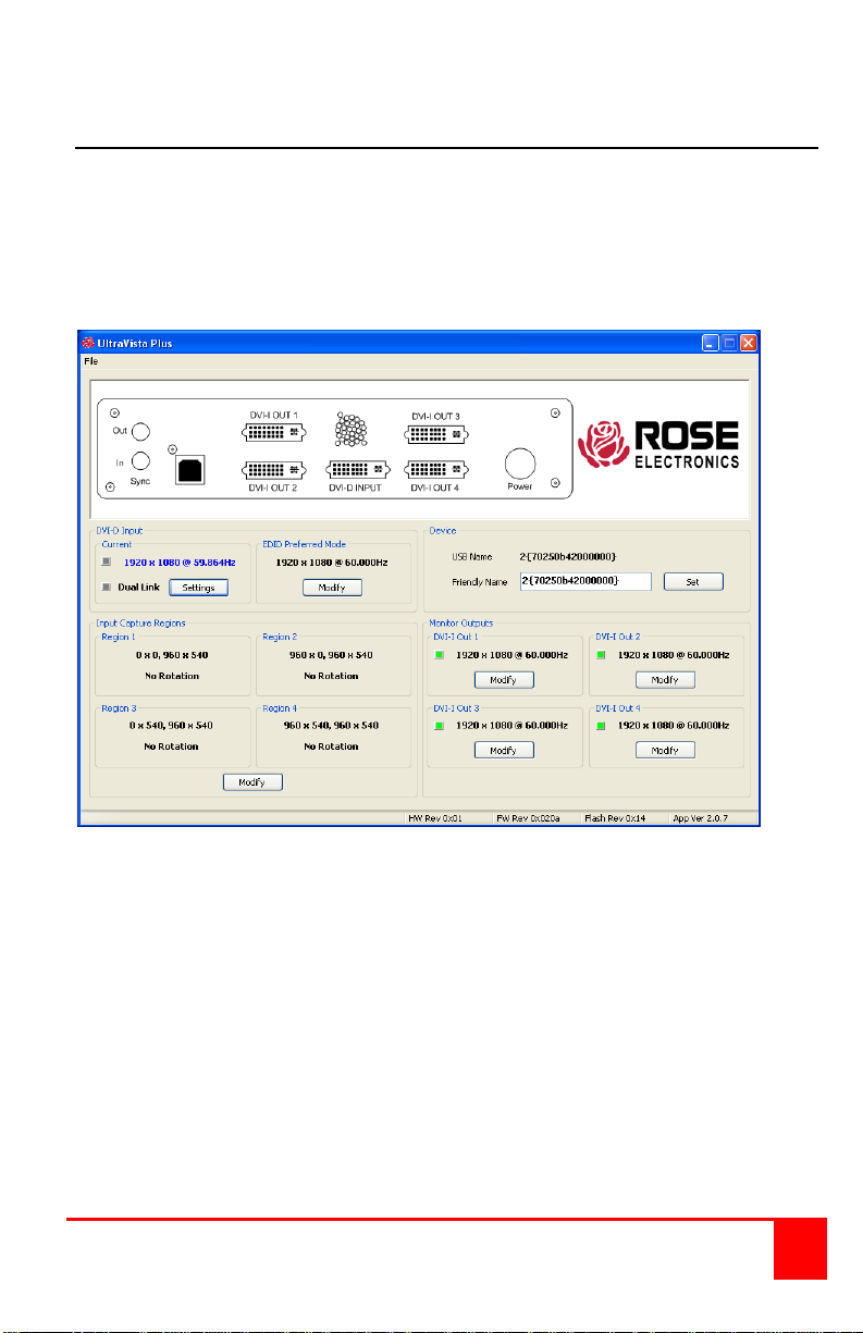
The main control application windo w is divided into the following groups:
Connection Diagram
Device
DVI-D Input
Input capture region
Monitor Outputs
Connection diagram
The connection diagram shows a view of the rear panel of the UltraVista
Plus.
Device section
The unique USB device name that is connected is displayed in the Device
group. It is possible to associate a more user friendly name such as “First
Four Outputs”. The friendly name is stored in non-volatile storage on the
UltraVista Plu s and can to help identify the device during future
configuration sessions. Specific devices connected to your PC can be
selected using the Select Device command on the File Menu. The UltraVista
Plus’s will be listed by the USB Device or by a previously configured friendly
name.
8 UltraVista Plus Installation and Operations Manual
Page 13
DVI-D Input section
The DVI-D Input group displays the current DVI mode that is being captured
(if any) and the preferred mode that has been programmed into the
UltraVista Plu s ’s EDID. Use the Modify button to update the EDID. The
small square to the left of the current input resolution indicates whether the
UltraVista Plu s has genlocked to the input source.
Green – The outputs are genlocked to the input dot clock and vertical sync
Red – The outputs are not genlocked
To change the timings of the input EDID click on the Modify button. The
following dialog wind ow will be displayed. From this window you can modify
the input EDID preferred mode timing standard, the display mode, and
detailed timing.
UltraVista Plus Installation and Operations Manual 9
Page 14
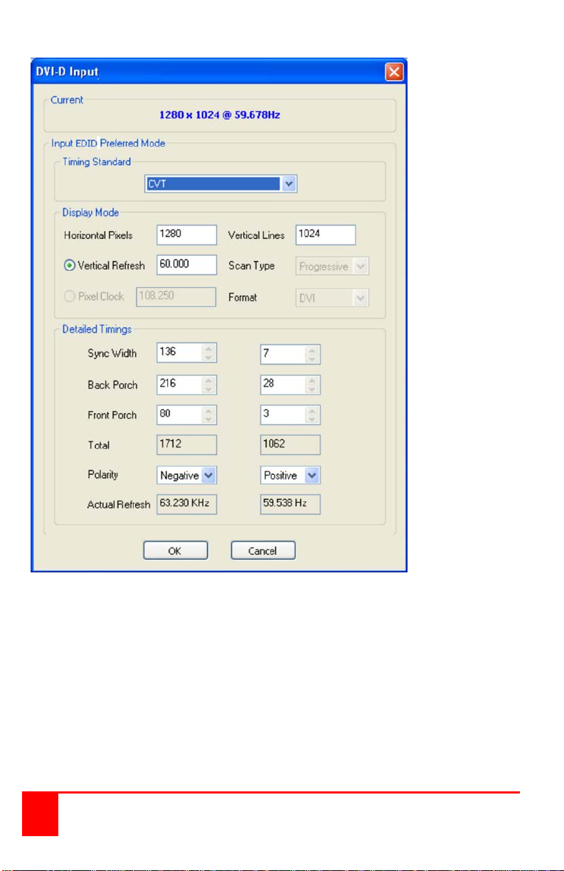
The DVI-D Input dialog displays the resolution of the current mode for
reference and allows the timings of the EDID preferred mode to be edited.
The dialog supports standard timing formulae such as:
VESA CVT
CVT Reduced Blanking
SMPTE (for HD modes)
VESA GTF
Custom
Selecting Auto from the drop down list will typically default to the VESA CVT
algorithm, which best matches typical standard VESA output modes. CVT
Reduced Blanking is recommended to minimize dot clocks and maximize
DVI cable lengths.
10 UltraVista Plus Installation and Operations Manual
Page 15
Selecting Custom allows the timing parameters to be edited. It should be
noted that you will need to select between the use of Pixel Clock or Vertical
Refresh, since these are mutually excusive parameters.
When editing is completed, clicking OK writes the preferred mode into the
EDID but may not automatically affect the input mode that is being captured.
It may be necessary to force the graphics device in the host machine to
detect the new preferred mode. This can be done by selecting Detect on the
Screen Resolutions dialog box (Windows® 7) or by disconnecting the
graphics source from the UltraVista Plus and reconnecting.
All modifications to the input settings can be saved as a .vqs file, removing
the requirement to input the same settings again. To save the settings select
the Save… command in the File menu. To open a saved .vqs file select the
Open… command.
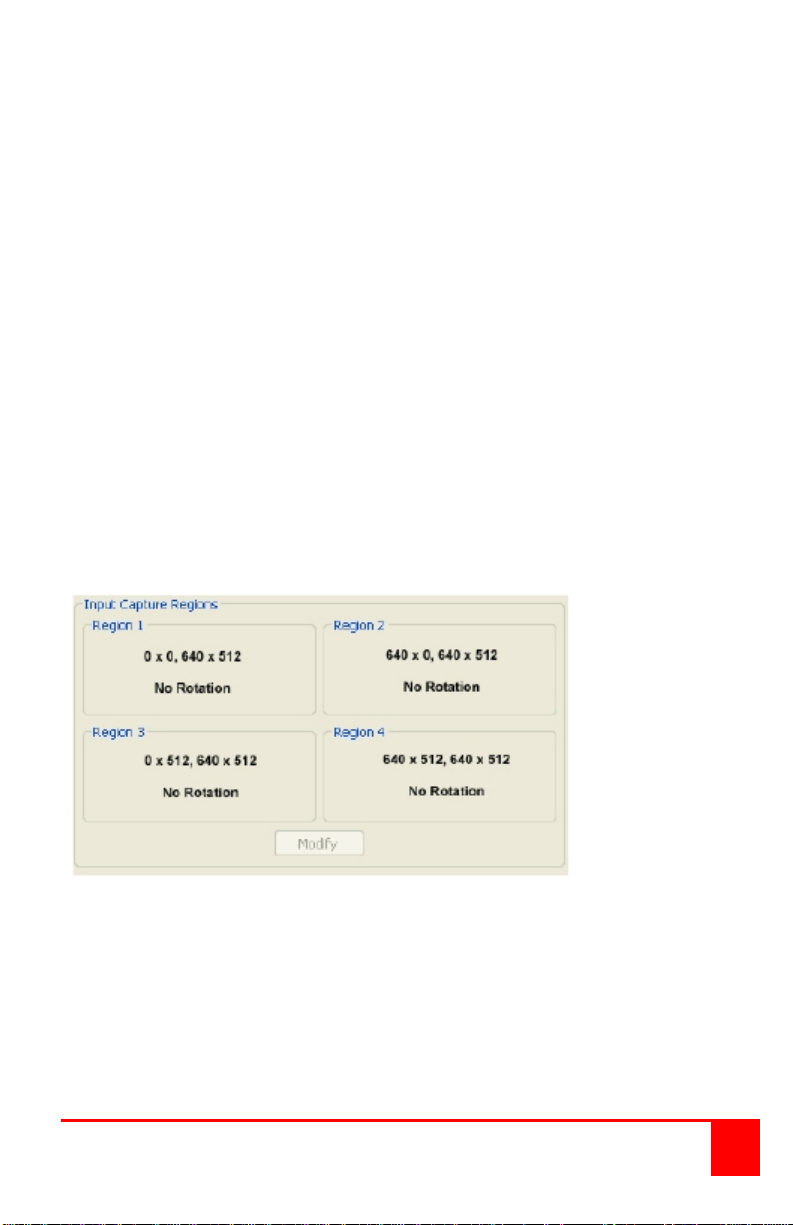
Input Capture Regions
Each output of the UltraVista Plus can select a different region of the input
source image. This dialog displays the settings of each region (region 1
corresponds to output 1 etc).
The numbers denote the top, left, width and height coordinates of the region
that is to be displayed. Note, these are described in terms of the current
active input resolution. If the input resolution changes, the capture region
coordinates scale to the new input resolution in order to maintain the same
proportions.
To modify any of these settings click on Modify to display the edit dialog.
UltraVista Plus Installation and Operations Manual 11
Page 16
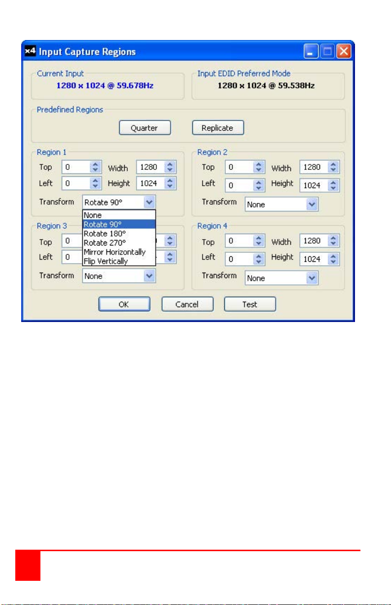
Predefined Regions
For ease of use, there are preset buttons to select the two most popular
configurations: Quarter or Replicate.
Quarter
The first monitor displays the top left hand quarter of the input image, the
second monitor the top right, the third the bottom left etc. This mode of
operation can be used to drive four monitors in a 2x2 arrangement from a
single high resolution input.
Replicate
Each output displays the entire input image. The output monitors can be
driven at the same resolution (with different timings, if necessary) or a
higher resolution.
There are no restrictions (other than the resulting scale factor must be 1:1 or
upscale) in the region settings, so it is possible to have regions overlapping,
or to program in gaps, etc. Additionally each region can have a transform
12 UltraVista Plus Installation and Operations Manual
Page 17

such as rotation or flipping applied to it (after cropping) in order to support
different output monitor orientations.
Please note that there may be instances where a setting stored in nonvolatile memory which was valid when it was store d (i.e. the scale factors
from input to output were 1:1 or greater) may subsequently require downscaling if the resolution of the input increases. In this case the firmware will
adjust the scaling factors to give a 1:1 crop of the input, centered on the
original region. In order to signal that at least one output is no longer exactly
honoring the programmed region setting, the front panel status light will not
be illuminated.
All modifications to the Region settings can be save as a .vqs file, removing
the requirement to input the same settings again. To save the settings select
the Save… command in the File menu. To open a saved .vqs file select the
Open… command.
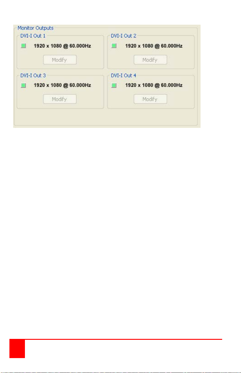
Monitor Outputs
The Monitor Outputs group shows the actual resolution and refresh rate that
each of the four Ultr a Vis ta Plus outputs is currently providing. To see more
information such as whether this is an analog RGB or DVI mode, if it is the
monitor EDID preferred mode or a default mode programmed into the
UltraVista Plu s , along with detailed timing information, click on the Modify
button for the required output.
The genlock status is indicated by the small colored squares:
Green
The outputs are genlocked to a common reference clock, and the Vsync of
the first monitor. If the Input genlock light is green (see above), then the
reference clock is taken from the input DVI source, and the system is fully
genlocked to this source. If the input genlock indicator is red, then the
outputs are genlocked together, but are not related to the input sync.
Red
The outputs are NOT genlocked
UltraVista Plus Installation and Operations Manual 13
Page 18
Individual monitor outputs can be configured by clicking on the
corresponding Modify button. This will bring up a timing dialog similar to that
of the input timings. This dialog is shown below.
14 UltraVista Plus Installation and Operations Manual
Page 19
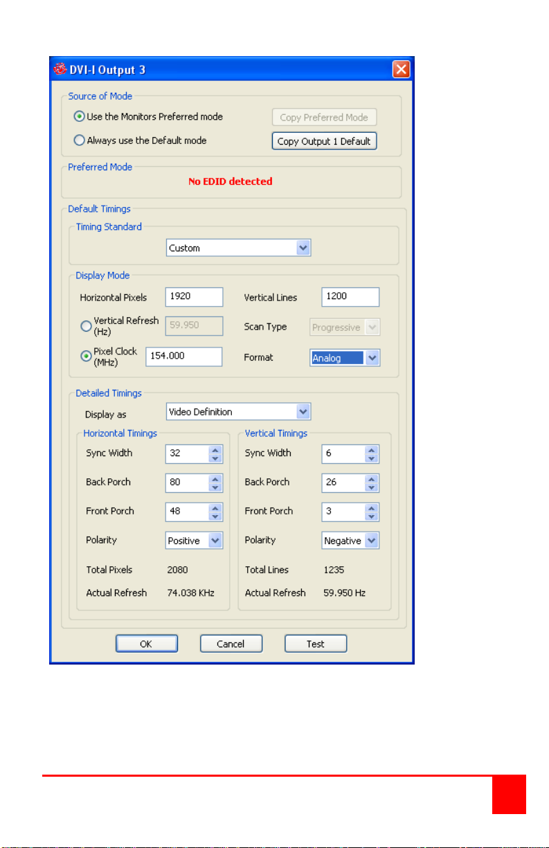
The source of mode selection controls whether the UltraVista Plus output
should take its timing values and resolution from the preferred mode of the
monitor that is connected, or use its internally programmed ‘default’ mode.
Please note that only the internal default timings can be edited in this dialog.
UltraVista Plus Installation and Operations Manual 15
Page 20

If Use the Monitors Preferred Mode is selected, but no valid EDID can be
read from the attached monitor, then the Ultr aV ista Pl us firmware will
program the output to use the default mode timings.
The rest of the dialog is identical to that for setting the Input timings, with the
exception that for the output monitors it is possible to select Analog RGB
(“VGA”) output as well as DVI.
All modifications to the Output settings can be save as a .vqs file, removing
the requirement to input the same settings again. To save the settings select
the Save… command in the File menu. To open a saved .vqs file select the
Open… command.
Finally there is a Test button which should be used when defining a default
mode that you are not sure the attached monitor can support. In test mode,
the output timings are programmed, but they are not saved to non-volatile
memory on the UltraVis t a P lus until the OK button is pressed to accept the
mode.
16 UltraVista Plus Installation and Operations Manual
Page 21

SAFETY
Product Safety
The UltraVista Plus has been tested for conformance to safety regulations
and requirements, and has been certified for international use. Like all
electronic equipment, the UltraVista Plus should be used with care. To
protect yourself from possible injury and to minimize the risk of damage to
the Unit, read and follow these safety instructions.
Follow all instructions and warnings marked on this Unit.
Except where explained in this manual, do not attempt to service this
Unit yourself.
Do not use this unit near water.
Assure that the placement of this Unit is on a stable surface or rack
mounted.
Provide proper ventilation and air circulation.
Keep power cord and connection cables clear of obstructions that might
cause damage to them.
Use only power cords, power adapter and connection cables designed
for this Unit.
Use only a grounded (three-wire) electrical outlet.
Use only the power adapter provided with the U nit.
Keep objects that might damage this Unit and liquids that may spill,
clear from this Unit. Liquids and foreign objects might come in contact
with voltage points that could create a risk of fire or electrical shock.
Operate this Unit only when the cover is in place.
Do not use liquid or aerosol cleaners to clean this Unit. Always unplug
this Unit from its electrical outlet before cleaning.
Unplug this Unit from the electrical outlet and refer servicing to a
qualified service center if any of the following conditions occur:
The power cord or connection cables are damaged or frayed.
The Unit has been exposed to any liquids.
The Unit does not oper at e nor mally when all operating instructions
have been followed.
The Unit has been dropped or the case has been damaged.
The Unit exhibits a distinct change in performance, indicating a
need for service.
UltraVista Plus Installation and Operations Manual 17
Page 22
MAINTENANCE and SUPPORT
Service Information
Maintenance and Repair
This Unit does not contain any internal user-serviceable parts. In the event
a Unit needs repair or maintenance, you must first obtain a Return
Authorization (RA) number from Rose Electronics or an authorized repair
center. This Return Authorization number must appear on the outside of the
shipping container.
See Limited Warranty for more information.
When returning a Unit, it should be double-packed in the original container
or equivalent, insured and shipped to:
Rose Electronics
Attn: RA__________
10707 Stancliff Road
Houston, Texas 77099 USA
Technical Support
If you are experiencing problems, or need assistance in setting up,
configuring or operating your UltraVista Plus unit, consult the appropriate
sections of this manual. If, however, you require additional information or
assistance, please contact the Rose Electronics Technical Support
Department at:
Technical Support hours are from: 8:00 am to 6:00 pm CST (USA), Monday
through Friday.
Please report any malfunctions in the operation of this Unit or any
discrepancies in this manual to the Rose Electronics Technical Support
Department.
18 UltraVista Plus Installation and Operations Manual
Page 23
Appendices
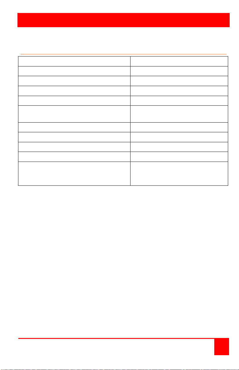
Part Number
P/N VWL-D122DDL
Resolution
2048 x 2048 (up to 2.5Mpixel)
Single Link DVI or Analog RGB output
Up to 165 Mpixels/s
Dual Link DVI capture
Up to 330 Mpixels/s
USB 2.0
Full speed (12Mbits/s)
Power
100-240VAC adapter to
5VDC, 11W
Operating Temperature
32° - 96°F (0° - 35°C)
Up Scaling
64x original surface area
Input surface
4k x 4k Max
MTBF
50,000 hrs.
Dimensions Width
Height
9.25” (235mm)
1.75” (44mm)
Appendix A – Specifications
UltraVista Plus Installation and Operations Manual 19
Depth
6.90” (175mm)
Page 24
10707 Stancliff Road Phone: (281) 933-7673
Houston, Texas 77099 WWW.ROSE.COM
 Loading...