

Rose electronics RV2-CKVM15A, RV1-KM, RV1-LCD17, RV1-LCD19, RV1-KVM15C Quick Start Manual
...Page 1
RackView
Rack Mountable KVM Drawer with optional KVM Switch
10707 Stancliff Road Phone: (281) 933-7673
Houston, Texas 77099
WWW.ROSE.COM
TM
Quick Start Guide
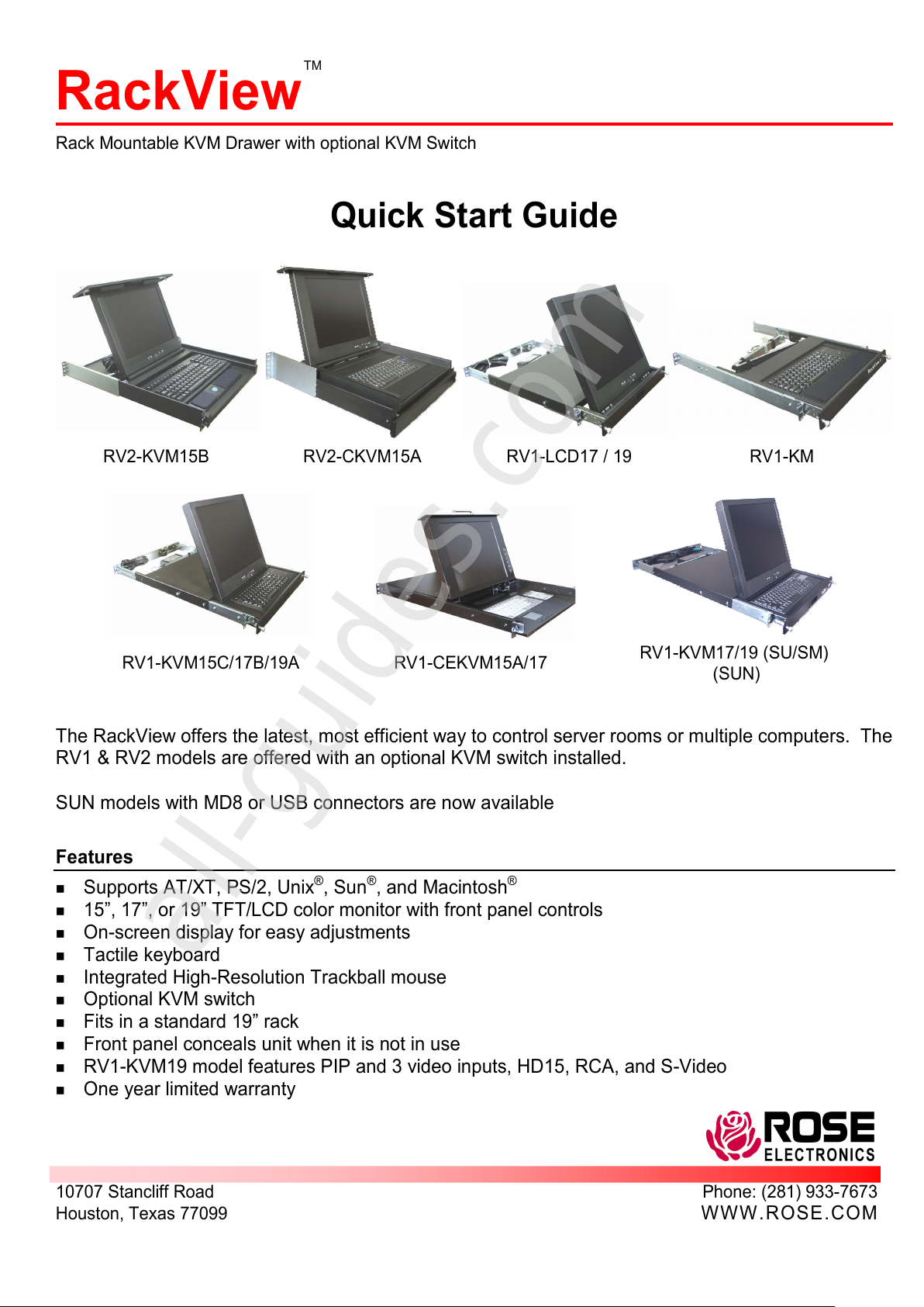
RV2-KVM15B RV2-CKVM15A RV1-LCD17 / 19 RV1-KM
RV1-KVM15C/17B/19A RV1-CEKVM15A/17
RV1-KVM17/19 (SU/SM)
(SUN)
The RackView offers the latest, most efficient way to control server rooms or multiple computers. The
RV1 & RV2 models are offered with an optional KVM switch installed.
SUN models with MD8 or USB connectors are now available
Features
Supports AT/XT, PS/2, Unix®, Sun®, and Macintosh®
15”, 17”, or 19” TFT/LCD color monitor with front panel controls
On-screen display for easy adjustments
Tactile keyboard
Integrated High-Resolution Trackball mouse
Optional KVM switch
Fits in a standard 19” rack
Front panel conceals unit when it is not in use
RV1-KVM19 model features PIP and 3 video inputs, HD15, RCA, and S-Video
One year limited warranty
All manuals and user guides at all-guides.com
all-guides.com
Page 2

Package contents
RackView Drawer assembly
Trackball driver (on floppy diskette)
Video monitor users manual (Not included with model RV1-KM)
Power cord (US only)
Rack mounting cage nuts
Unpacking
DO NOT DISCARD THE SHIPPING CONTAINER, PACKING MATERIAL OR SHIPPING PLATE.
Tools needed - #2 Phillips head screwdriver
Remove RackView assembly from the shipping container by removing the top protective foam and lifting
from the middle of the unit.
Remove other protective foam and covering.
Set the unit on a flat surface and open the monitor far enough to remove the protective foam material, and
then close the monitor.
Remove the shipping plate from the back of the unit’s rail assembly (if applicable).
Things to note
This installation guide covers the installation of the RackView models. If the RackView is ordered with the
Rose KVM switch option, please refer to the switch’s manual for cable connectivity and switch
configuration.
Do not adjust the front rail brackets.
The rack dimensions must be 19” x 23” to 28”
It is recommended that two people perform the installation.
Specifications
Monitor
Panel 15”, 17”, or 19” TFT/LCD active matrix color
Max. Resolution 15” – 1024 x 768 @ 75Hz
17” – 1280 x 1024 @ 75Hz
19” – 1280 x 1024 @ 75Hz
Video compatibility SVGA, VGA, XGA, RGB
Regulations UL, Energy Star, VESA DPMS
Connectors 15” & 17” models - HD15
19” model – HD15, RCA, S-Video (With PIP)
Keyboard
Selectable PS/2 or AT
Power +5V DC/300mA max.
Connector MiniDin-6
Trackball mouse
Compatibility PS/2 (MiniDIN-6) or serial (DB9)
Resolution Variable 20-6400 dpi
Tracking speed 500 mm/sec
Connector MiniDin-6
RackView
Temp/Humidity 32°F - 104°F / 0°C - 40°C, 5% - 80% RH
All manuals and user guides at all-guides.com
Page 3
RackView Installation
1U assembly (RV1 models)
1. Tilt the RackView assembly enough to fit through the rack opening. Guide it through the rack until the rear
mounting flanges are just past the rear of the rack rails. Make sure the front mounting flanges remain on
the outside of the front rack rails.
2. Level the RackView assembly (left to right) and secure the rear mounting flanges (left and right) to the rear
rack rails using the included mounting screws (4 screws).
3. Secure the front mounting flanges (left and right) to the front rack rails using the included mounting screws
(4 screws). Make sure the RackView assembly is level (front to back).
4. Check that the RackView assembly will slide in flush with the front rack rails, and open fully with no binding.
2U assembly (RV2 models)
1. Slide the left and right finger brackets off from the RackView rail assembly and mount them to the rear rack
rails using the provided mounting screws (4 screws). Make sure the finger brackets are level.
2. Guide the RackView assembly through the rack, lining up the left and right slide rails with the left and right
finger brackets. Slide the assembly over the rear finger brackets until the front mounting flanges are flush
with the front rack rails.
3. Secure the front mounting flanges to the front rack rails using the provided mounting screws (4 screws).
Make sure the RackView assembly is level, front to back and side to side.
4. Check that the RackView assembly will slide in flush with the front rack rails, and open fully with no binding.
Keyboard/mouse assembly
Refer to the 1U assembly installation procedure for the RV1-KM model installation.
LCD monitor assembly
Refer to the 1U assembly installation procedure for the RV1-LCD model installation.
System Installation
1. Remove the cable ties that secure the power cord and KVM cables.
2. Connect the power cord to the power adapter and to 110/220-volt power source.
3. Locate the keyboard, video monitor, and mouse cables on the RackView and connect these
cables to the corresponding ports on a PC or the KVM connector on a Rose switch. When
connecting to a Rose switch, a KVM adapter cable may be required if the KVM switch’s connector
is a DB25F. Before connecting any CPUs to a Rose switch, verify that the CPUs video resolution
is set-up to be compatible with the RackView’s monitor resolution. Refer to the specific Rose
switch manual for connecting and configuring the CPUs.
4. Apply power to the RackView and the CPU or Rose switch.
5. If the Trackball is erratic or inoperable, the Trackball driver may need to be installed on the
connected CPU (Trackball driver provided on floppy)
6. Refer to the monitor manual for information concerning the set-up and controls.
All manuals and user guides at all-guides.com
Page 4

Copyright Rose Electronics 2002. All rights reserved.
No part of this manual may be reproduced, stored in a retrieval system, or transcribed in any form or any means, electronic or mechanical, including photocopying and
recording, without the prior written permission of Rose Electronics.
Rose Electronics Part # MAN-RV-1.4
Printed In the United States of America – Revision 1.4
KVM switch options
The RackView can be ordered with an optional Rose Electronics KVM switch. The UltraView Pro, ServeView
Pro and the UltraMatrix 2xE and 4xE models can easily be installed in the RackView. They mount to the rear
RackView rails on the provided brackets. Contact Rose Electronics Technical support for assistance.
Maintenance and Repair
This unit does not contain any user-serviceable parts. In the event a Unit needs repair or maintenance, you
must first obtain a Return Authorization (RA) number from Rose Electronics or an authorized repair center.
This Return Authorization number must appear on the outside of the shipping container.
When returning a Unit, it should be packed in the original container or equivalent, insured and shipped to:
Rose Electronics
Attn: RA__________
10707 Stancliff Road
Houston, Texas 77099 USA
Technical Support
If you are experiencing problems, or need assistance in setting up, configuring or operating your Rose
Electronics equipment, consult the appropriate sections of this manual. If, however, you require additional
information or assistance, please contact the Rose Electronics Technical Support Department at:
Phone: (281) 933-7673
E-Mail: TechSupport@rose.com
Web: www.rose.com
Technical Support hours are from: 8:00 am to 6:00 pm CST (USA), Monday through Friday.
Please report any malfunctions in the operation of this Unit or any discrepancies in this manual to the Rose
Electronics Technical Support Department.
All manuals and user guides at all-guides.com
 Loading...