

Page 1
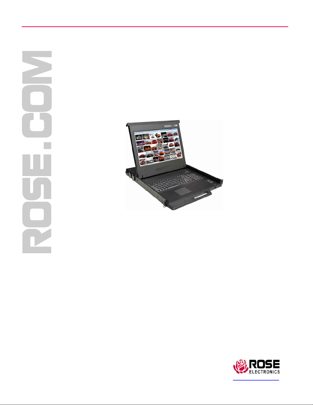
Rackview High Resolution – KVM Rack Drawer
INSTALLATION AND
OPERATIONS MANUAL
Widescre e n 1 7” LCD
Ultra High Res olution
1920 x 1200
Rose Electronics 10707 Stancliff Road
Houston, Texas 77099
Phone (281) 9337673 WWW.ROSE.COM
Page 2

.
Page 3

Page 3
KVM Rack Drawer (FHD) High Resolution WWW.ROSE.COM
LIMITED WARRANTY
Rose
Electronics warrants the
purchase
from Rose
Electronic
year warranty period, Rose Electronics will, at its option, repair or replace the Unit as set forth below. Repair
parts and
Electronics.
replacement
This limited warranty does not include service to repair damage to the Unit
disaster, abuse, or
units will be either
unauthorized modification
Limited
Warranty
Electronics
service may be obtained by
or an
authorized
If this Unit is delivered by mail, you agree to insure the Unit or assume the risk of loss or
prepay
shipping
charges to the
equivalent. You must call for a return authorization number first. Under no
without a return
authorization
information.
ALL EXPRESS A
MERCHANTABILITY
ND IMPLIED
AND
PERIOD OF ONE YEAR FROM THE DATE OF
OR
IMPLIED, W
LONG AN IMPLIED
ILL APPLY AFTER THIS PERIOD. SOME STATES DO NOT ALLOW
W ARRANTY
IF THIS PRODUCT IS NOT IN GOOD
YOUR SOLE
ROSE
REMEDY
ELECTRONICS
BE LIABLE TO YOU FOR ANY DAMAGES
INCLUDING ANY LOST PROFITS, LOST SAVINGS OR OTHER
DAMAGES ARISING OUT OF THE USE OF OR THE
ELECTRONICS
OR AN
DAMAGES, OR FOR ANY CLAIM BY ANY OTHER PARTY.
SOME STATES DO NOT ALLOW THE EXCLUSION OR
DAMAGES FOR CONSUMER PRODUCTS, SO THE ABOVE MAY NOT
GIVES YOU
SPECIFIC
FROM STATE TO STATE.
IBM, AT, and PS
/2 are trademarks of International Business Machines Corp. Microsoft and Microsoft
are registered trademarks of Microsoft Corp. Any other trademarks mentioned in this manual are
to be the property of the
.
Copyright © Rose Electronics 2013. All rights reserved.
No part of this manual may be reproduced, stored in a retrieval system, or transcribed in any form or any means, electronic or mechanical, including
photocopying and recording, without the prior written permission of Rose Electronics.
Rose Electronics Part # MAN-RV1-CAKVT17-FHD
Printed In the United States of America – Revision 1.0
Rackvie w Pr o du c t
to be in good working order for one year from the date of
s. Should this product fail to be in good working order at any time during this one-
reconditioned
of the
delivering
repair center providing a proof of
or new. All replaced parts
Unit, including
static discharge and power surges.
become
resulting
the property of Rose
from
this unit during the one-year warranty period to Rose
purchase
date.
damage
warranty
number. Contact an
W ARRANTIES
FITNESS
service location, and to use the original shipping container or its
FOR A
circumstances
authorized
repair center or Rose
FOR THIS PRODUCT INCLUDING THE
PARTICULAR
PURCHASE,
PURPOSE, ARE LIMITED IN
AND NO
WARRANTIES, W HETHER EXPRESS
will a unit be accepted
Electronics
for further
WARRANTIES
DURATION
LIMITATIONS
LASTS, SO THE ABOVE
W
ORKING ORDER AS W ARRANTED ABOVE,
SHALL BE
AUTHORIZED
REPLACEMENT
DEALER HAS BEEN ADVISED OF THE
LEGAL RIGHTS AND
trademark
owner.
OR REPAIR AS
YOU
MAY ALSO HAVE OTHER
LIMITATION
INABILITY
LIMITATION
MAY NOT APPLY TO YOU.
PROVIDED ABOVE.
INCIDENTAL
OR
TO USE SUCH
POSSIBILITY
OF
INCIDENTAL
APPLY
TO YOU. THIS W
RIGHTS W
IN NO EVENT WILL
CONSEQUENTIAL
PRODUCT,
EVEN IF ROSE
OF SUCH
OR
CONSEQUENTIAL
HICH MAY
in transit, to
ARRANTY
acknowledged
accident,
OF
TO A
ON HOW
VARY
W
indows
Page 4
Page 4
KVM Rack Drawer (FHD) High Resolution WWW.ROSE.COM
Table of Contents
Safety Instructions Page 5
Pre-Installation and Package Contents Page 6
Rackview Layout Diagram and Dimensions Page 7-8
Installation Page 9-10
Connection to a Server/KVM Switch Page 11
OSD (On-Screen Display Control Panel) Operation Page 12
PIP and PBP Page 13-14
Video Format Page 15
Product Options Page 15
Specifications Page 16
Product Codes Page 16
Technical Support Page 17
Page 5

Page 5
KVM Rack Drawer (FHD) High Resolution WWW.ROSE.COM
Safety Instructions
Please read all of these instructions carefully before you use the device. Save this manual for
future reference.
•
Unplug equipment before cleaning. Don’t use liquid or spray detergent; use a moist cloth.
• Keep equipment away from excessive humidity and heat. Preferably, keep it in an air-conditioned
environment with
• When installing, place the equipment on a sturdy, level surface to prevent it from accidentally
falling and causing dam
• When the equipment is in an open position, do not cover, block or in any way obstruct the gap
between it and the
•
Arrange the equipment’s power cord in such a way that others won’t trip or fall over it.
If you are using a power cord that didn’t ship with the equipment, ensure that it is rated for the
•
voltage and current
cord should be higher than the one listed
•
Observe all precautions and warnings attached to the equipment.
If you don’t intend on using the equipment for a long time, disconnect it from the power outlet to
•
prevent it being damaged by transient overvoltage.
• Keep all liquids away from the equipment to minimize the risk of accidental spillage. Liquid spilled
on to the power
• Only qualified service personnel should open the chassis. Opening it yourself could damage the
equipment and invalidate its warranty.
• If any part of the equipment becomes damaged or stops functioning, have it checked by qualified
service personnel.
Regulatory Notices Federal Communications C o mmission (FCC)
This equipment has been tested and found to comply with the limits for a Class B digital device,
pursuant to Part 15 of the FCC rules. These limits are designed to provide reasonable protection
against harmful interference in a residential installation.
Any changes or modifications made to this equipment may void the user’s authority to operate this
equipment. This equipment generates, uses, and can radiate radio frequency energy and, if not
installed and used in accordance with the instructions, may cause harmful interference to radio
communications.
However, there is no guarantee that interference will not occur in a particular installation. If this
equipment does cause harmful interfer ence to radio or tele vision reception, w hich can be determ ined
by turning the equipment off and on, the user is enc our aged t o try to correct the inter f er ence by one or
more of the following measures:
•
Re-position or relocate the receiving antenna.
•
Increase the separation between the equipment and receiver.
• Connect the equipment into an outlet on a circuit different from that to which the receiver is
connected.
supply or on other hardware may cause damage, fire or electrical shock.
temperatures not exceeding 40º Celsius (104º Fahrenheit).
age to other equipment or injury to persons nearby.
power supply. Proper air convection is necessary to keep it from overheating.
labeled on the equipment’s electri cal ratings lab el. The voltage rating on the
on the equipment’s ratings label.
Page 6

Page 6
KVM Rack Drawer (FHD) High Resolution WWW.ROSE.COM
Pre-Installation and Package Contents
Before Installation:
It is very important to mount the equipment in a suitable cabinet or on a stable surface.
Make sure the mounting location has good ventilation, is out of direct sunlight, and away from sources of
excessive dust, dirt, heat, water, moisture and vibration.
Unpacking:
The equipment comes with the standard parts shown in package content. Check and make sure they are
included and in good condition. If anything is missing, or damaged, contact your supplier immediately.
Package Contents:
1x Rackview Unit
1x Mounting Bracket set
1x Combo Cable for Video/Keyboard/Mouse (DVI/ USB or VGA/USB)
1x Power Cord
1x User Manual
1x set of screws and washers for assembly
Product Operation:
a) Power On Procedure
• Power on the Rackview (see power switch on back panel)
• Power on the KVM Switch or other connected product
• Power on the CPU
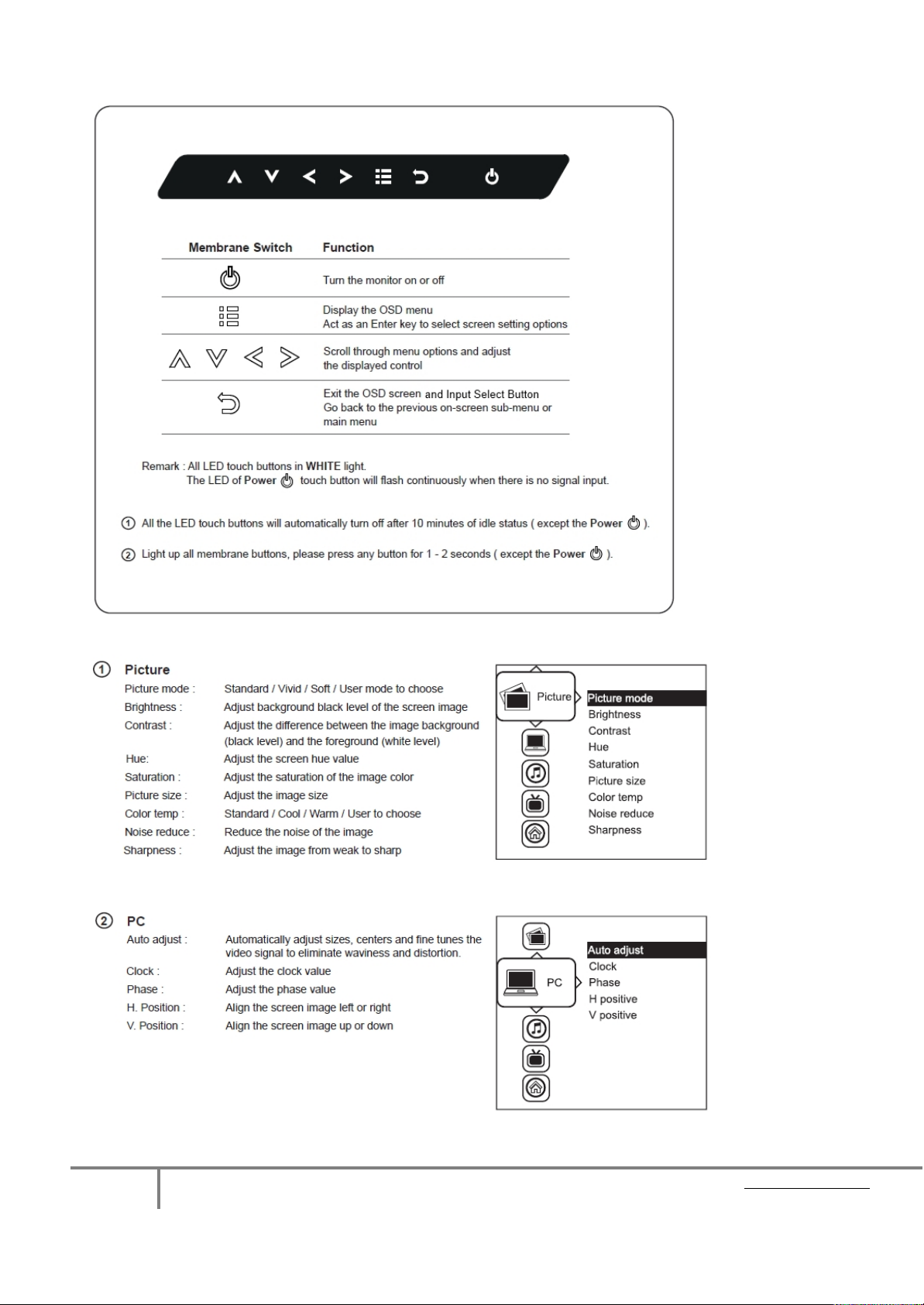
b) Video Input Select Button (see OSD Section, Page 12)
The Rackview remembers the last valid video input selection, so if the CPU input has changed, the user needs
to re-select the video input.
• Locate the “Video Input Select” button on the OSD display control panel
• Push the Video Input Sel ect butt on to togg le bet ween VG A and DVI Inp ut
• Select the appropriate Video Input format (VGA or DVI)
c) Cleaning Your Monitor
To clean your LCD safely, please follow these steps:
• Disconnect the po wer cord.
• Gently wipe the surface using a clean, dry microfiber cloth. Use as little pressure as possible.
Page 7
Page 7
KVM Rack Drawer (FHD) High Resolution WWW.ROSE.COM
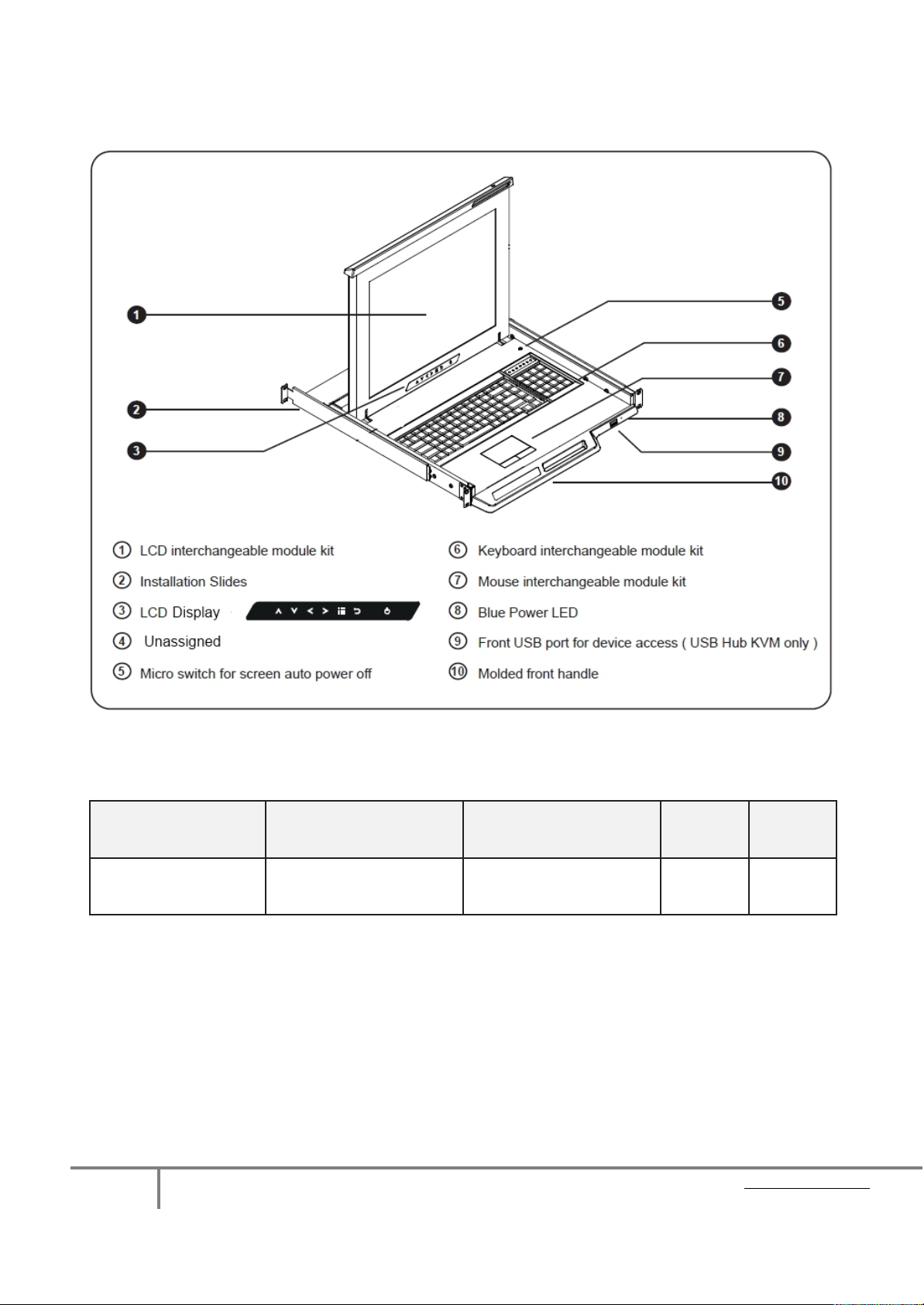
Rackview Layout Diagram & Dimensions
6
3
Model
RV1-CAKVT17/FHD
Product Dimension
(W x D x H) approx
441.6 x 480 x 44 mm
17.4 x 18.9 x 1.73 inch
Packing Dimension
(W x D x H) approx
590 x 823 x 140 mm
23.2 x 32.4 x 5.5 inch
Net
Weight
15 kg
33 lb
Gross
Weight
19 kg
42 lb
The package weight can vary with accessories included
Page 8
Page 8
KVM Rack Drawer (FHD) High Resolution WWW.ROSE.COM
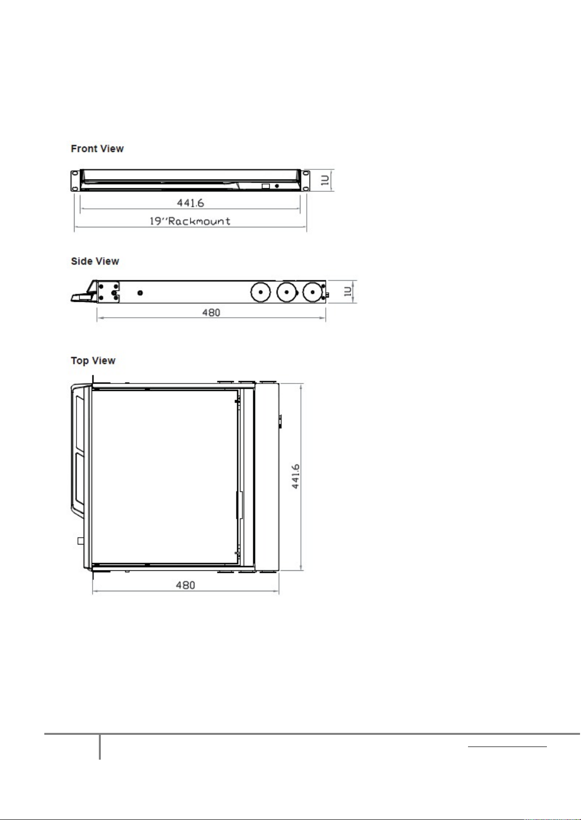
Rackview Dimensions
Unit: mm
1mm = 0.03937 inch
Page 9
Page 9
KVM Rack Drawer (FHD) High Resolution WWW.ROSE.COM
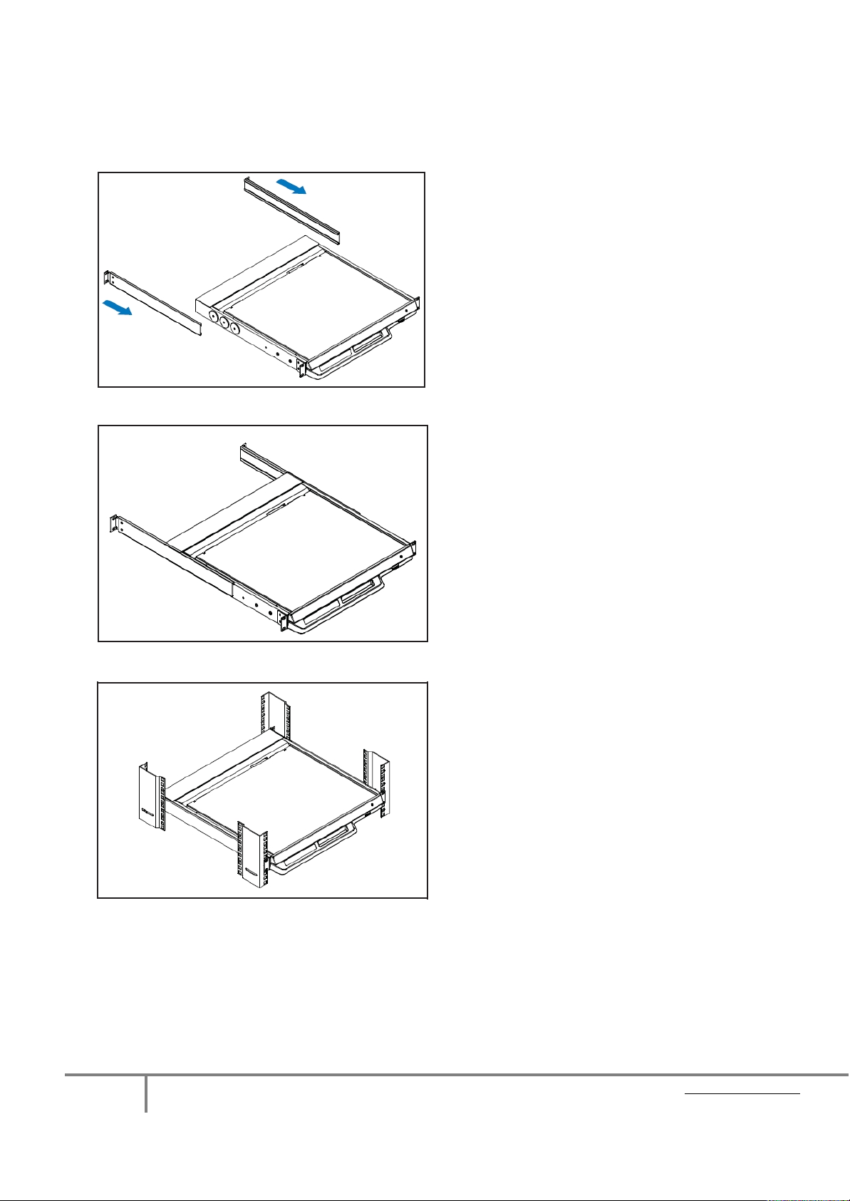
Installation of Rackview 17” High Re s olution
STEP 1
Insert the Left and Right rear-mounting slides
into the Rackview Console Drawer
STEP 2
Measure the depth of the front and rear rack rails
Align each rear-mounting slide to a suitable
length (depth)
STEP 3
Complete the Installation
Fix the Rackview Console Drawer into the Rack
Screws, cage nuts and cup washers are provided
Page 10
Page 10
KVM Rack Drawer (FHD) High Resolution WWW.ROSE.COM
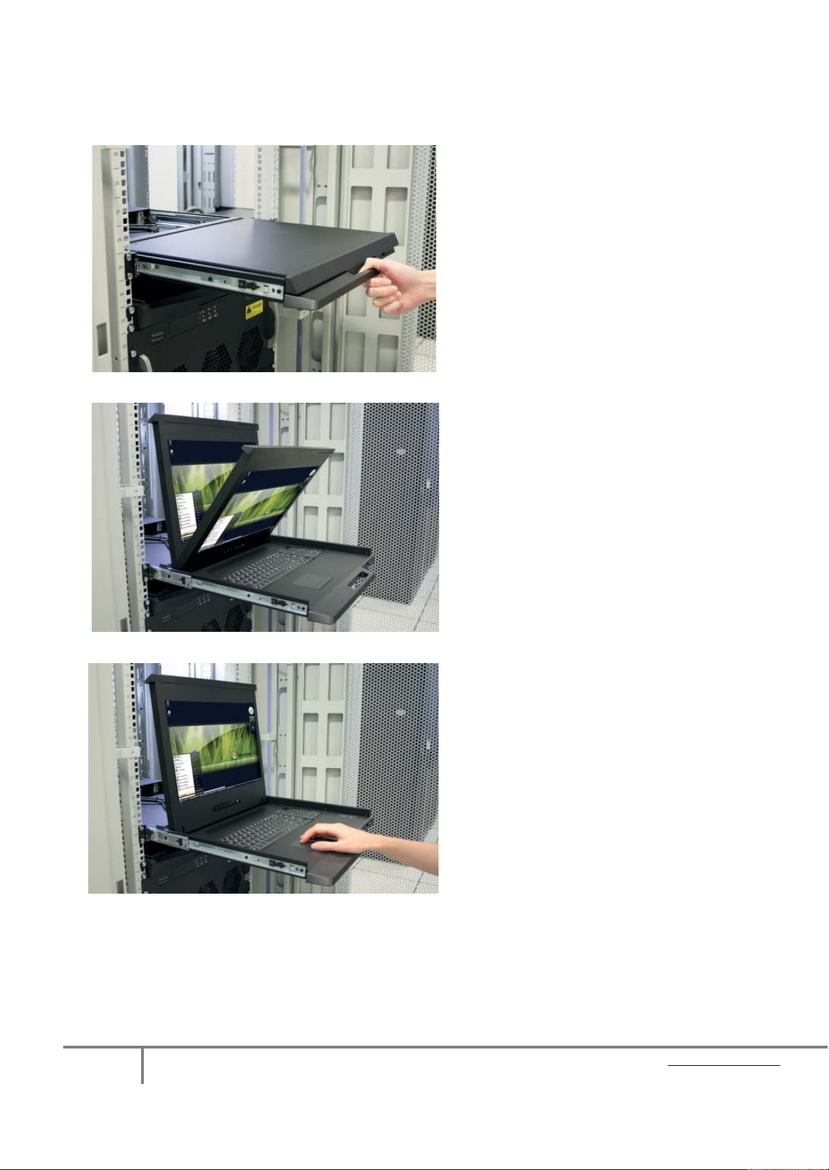
Installation – How to Unlock and Operate the Rackview 17” High Res
STEP 1
Hold the handle and slide out the Rackview
drawer
STEP 2
Flip up the LCD to a suitable viewing angle
STEP 3
Operate the Rackview Console Drawer
Page 11
Page 11
KVM Rack Drawer (FHD) High Resolution WWW.ROSE.COM
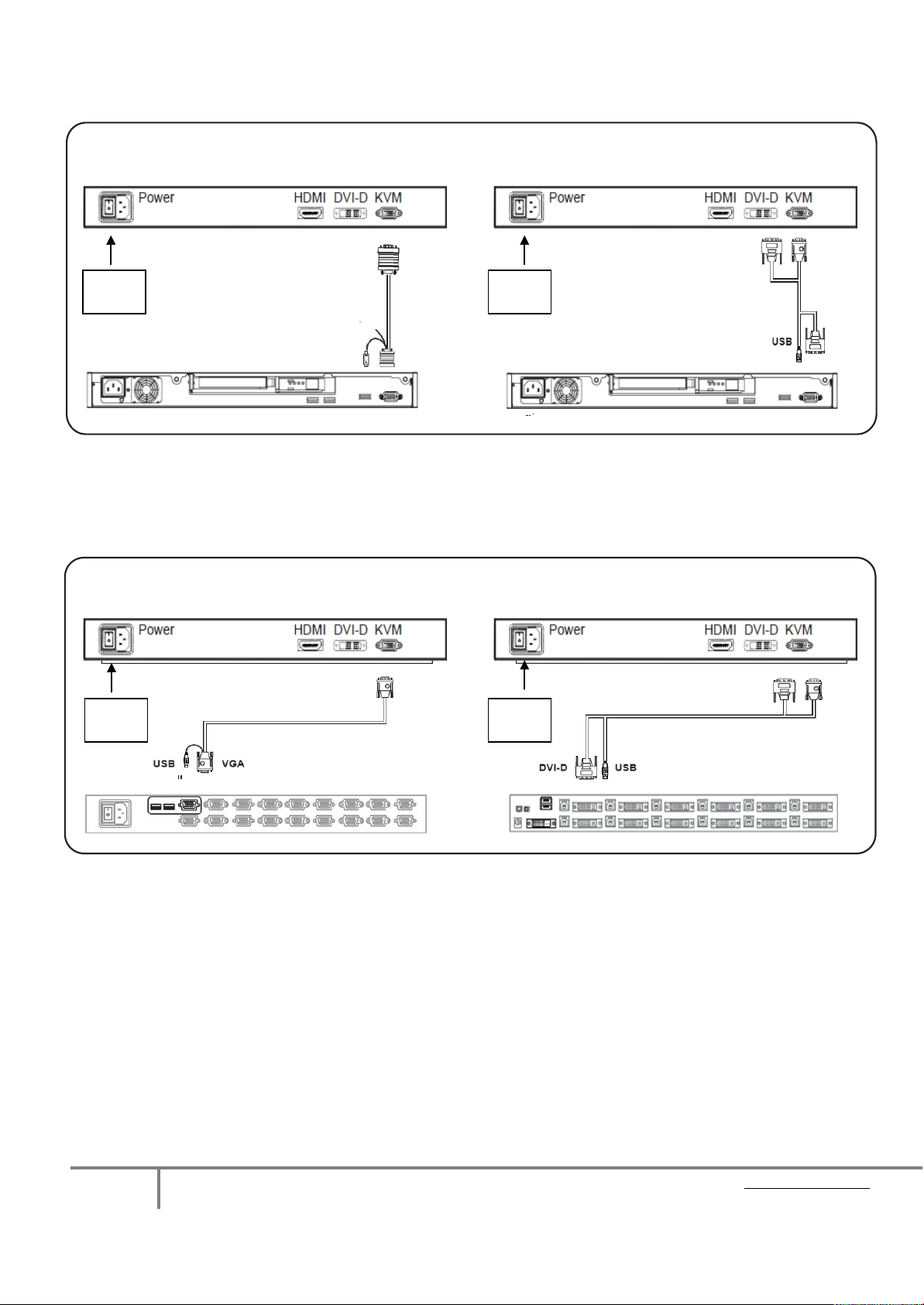
Connection to a USB Server
On/Off
Power
On/Off
Power
On/Off
Power
On/Off
Power
DVI/USB Switch
(sample connections)
Rackview LCD console drawer
KVM cable. VGA + USB
USB server
KVM cable. DVI + USB
USB Server
Connection to an external KVM switch
(sample connections)
Rackview LCD console drawer Rackview LCD console drawer
VGA/USB Switch
Note: Please request the cable required at time of order.
CAB-CMBVMUAC005 is for VGA to VGA + USB
CAB-CMBDVUAC005 is for DVI + VGA to DVI +USB
HDMI: The HDMI cable is optional (not included)
Caution : The Rackview LCD console drawer is hot-pluggable, but components of connected devices, such
as the servers and KVM switch, may not be hot-pluggable. Plugging and unplugging cables while servers
and KVM switch are powered-on may cause irreversible damage to the servers, KVM and LCD console
drawer. Before attempting to connect anything to the Rackview LCD console drawer, we suggest turning off
the power to all devices. Apply power to connected devices only after the Rackview LCD
console drawer
has been powered-on. Rose Electronics is not responsible for any product damage or warranty claims caused in this
way.
Page 12
Page 12
KVM Rack Drawer (FHD) High Resolution WWW.ROSE.COM
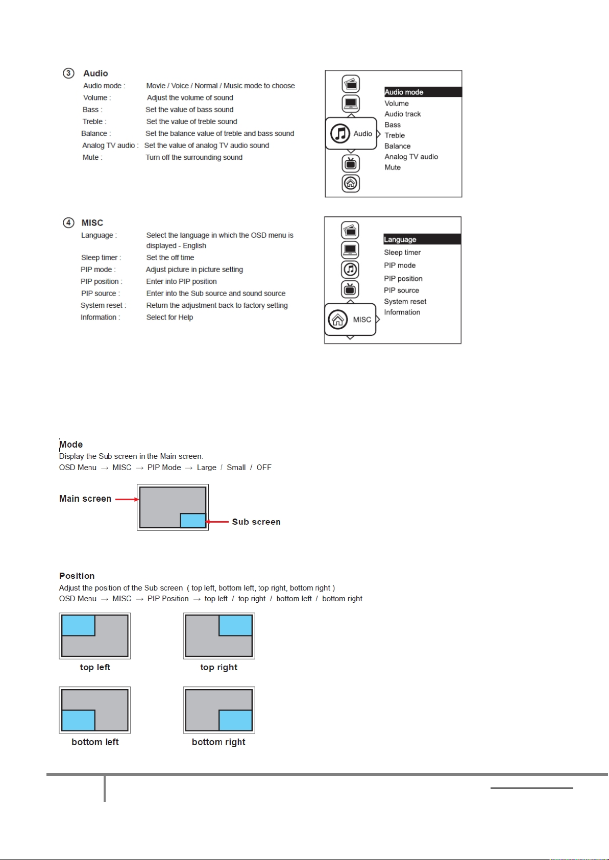
On-Screen Display Operation ( OSD )
Page 13
Page 13
KVM Rack Drawer (FHD) High Resolution WWW.ROSE.COM
Rackview Single Rail 17” FHD Page 6 www.rose
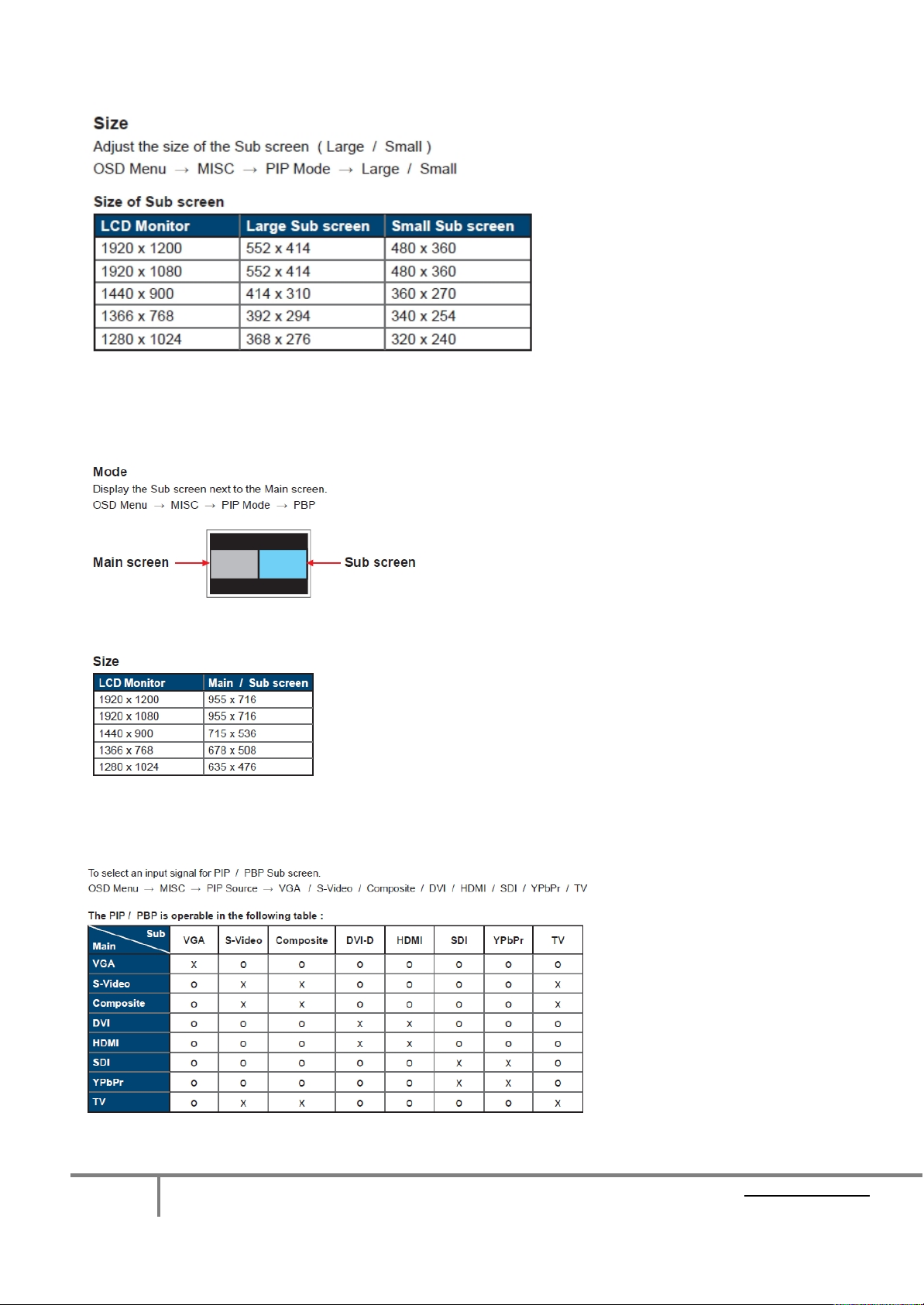
Picture In Picture and Pict ure By Picture Modes (PIP and PBP)
1. Picture-In-Picture (PIP)
Page 14
Page 14
KVM Rack Drawer (FHD) High Resolution WWW.ROSE.COM
2. Screen Size
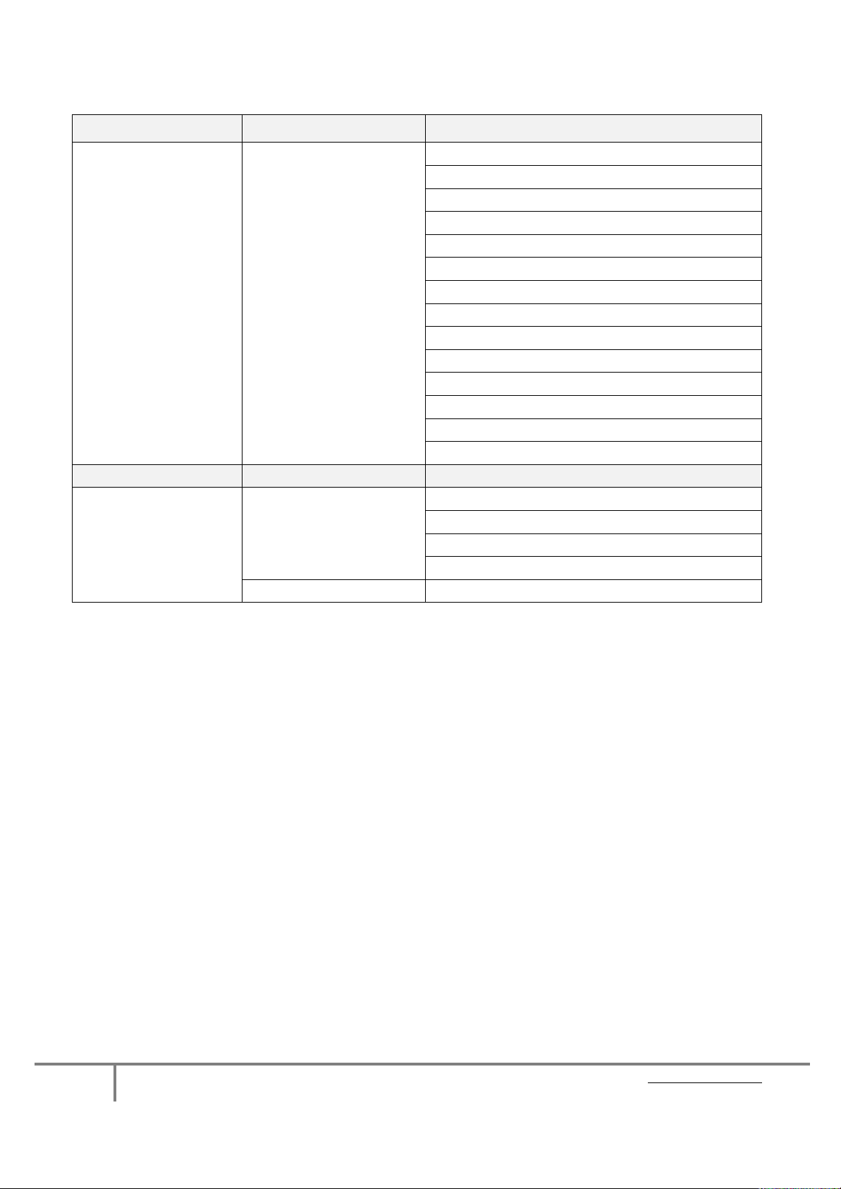
3. Picture-By-Picture (PBP)
4. PIP / PBP Source
Page 15
Page 15
KVM Rack Drawer (FHD) High Resolution WWW.ROSE.COM
PC Signal
Resolution/Refresh Rate
HDMI Input
PC Signal
Video Signal
Audio Signal
Video Format
DVI-D / VGA Input
1920 x 1200 x 60Hz
1360 x 768 x 60Hz
1280 x 1024 x 60Hz / 75Hz
1280 x 960 x 60Hz
1280 x 768 x 60Hz / 75Hz
1152 x 864 x 75Hz
1024 x 768 x 60Hz / 70Hz / 75Hz
848 x 480 x 60Hz
800 x 600 x 60Hz / 72Hz / 75Hz
720 x 400 x 70Hz
640 x 480 x 60Hz / 72Hz / 75Hz
640 x 400 x 70Hz
640 x 350 x 70Hz
Same as VGA
1080p : 60Hz
720p : 50 Hz / 60Hz
480p : 60 Hz
576p : 50 Hz
2 ch Linear PCM (32 / 44.1/48 Khz)
Product Options:
a) HDMI Cable. Add /HDMI to the product part number.
b) Audio. Add /A2 to the product part number.
c) 12/24/48VDC. Add /DCnn to the product part number.
Note 1: The /DC option includes additional power cord and power adapter.
Note 2: The /Audio and /DC options extend the Rackview chassis depth from 480mm (18.9”) to 530mm (20.9”).
Please check with Rose Electronics for pricing and availability of these options.
Page 16
Page 16
KVM Rack Drawer (FHD) High Resolution WWW.ROSE.COM
Rackview 17” High Resolution - LCD / Keyboard / Mouse Specifica ti on
Item
Description
Display Size
17.1" Widescreen TFT color LCD
Max. Resolution
1920 x 1200
Brightness (cd/m²)
Color Support
16.7 M, 8-bit
Contrast Ratio (typ.)
600:1
Dot Pitch (mm)
0.191
Display Area (mm)
Response Time (ms)
30
LCD Panel MTBF (hrs)
20,000
VGA Signal Input
Analog, 0.7Vp-p
DVI Signal
HDMI Signal
HDMI 1.1, CEA-861-D
Sync. Type (VGA)
Plug & Play DDC (DVI &
VESA EDID 1.3
DVI: (DVI-D) and HDMI
Audio Option
3.5mm with L/R Speakers. Impedance 30KΩ / 750mV. Speaker Power – 2*2W
Power Input
Compatibility
Multi-platform - Mix PCs, SUNs, IBMs, HPs & DELLs.
Regulation Approval
Operation
0˚ to 50˚C Degree
Storage
-5˚ to 60 ˚C Degree
Relative Humidity
Shock
10G acceleration (11ms duration)
Vibration
210
Viewing Angle (L/R/U/D)
Console Port
Power Consumption
Environmental
65/65/55/55
367.20 (H) x 229.50 V
DVI-D, TMDS Single-Link
Separate H/V, Composite, SOG
HD-15 connector for VGA / keyboard / mouse (Combo interface)
USB 5ft Cable: (1*HD15M to HD15M + USB)
Auto-sensing 100 to 240VAC, 50 / 60Hz
Screen ON = 34W or less, Power Saving Mode = 4W or less
FCC, CE
Operating: 20~90%, non-condensing
5~500Hz 1G RMS random vibration
Product Codes:
RV1-CAKVT17/FHD Rackview 17” High Resolution KVM Rack Drawer
Interface Cables: (only 1 cable is included. Sel ect with order)
/K1: CAB-CMBVMUAC005 HD15 to HD15 + (1) USB-A. (VGA +USB)
/K3: CAB-CMBDVUAC005 DVI-D + VGA(M) to DVI-I + (1) USB-A (DVI + USB)
Optional Items: (check with Rose Electronics for pricing and availability)
HDMI Cable
Audio Option
DC Voltage Option (12/24/48VDC)
Page 17
Page 17
KVM Rack Drawer (FHD) High Resolution WWW.ROSE.COM
Technical Support
If you are experiencing problems, or need assistance in setting up, configuring or operating your product,
consult the appropriate sections of this manual. If, however, you require additional information or
assistance, please contact the Rose Electronics Technical Support Department at:
Technical Support hours are from: 8:00 am to 6:00 pm CST (USA), Monday through Friday.
Please report any malfunctions in the operation of this Unit or any discrepancies in this manual to the Rose
Electronics Technical Support Department.
WWW.ROSE.COM [email protected] (800) 333 9343
Rose USA (281) 933 7673 Rose Europe +49 (0) 2454 969442 Rose Asia +65 6324 2322 Rose Australia +61 (0) 421 247083
Rose Electronics 10707 Stancliff Road Houston, Texas 77099
© Copyright 2013 Rose Electronics. All rights reserved. Specifications subject to change without notice
 Loading...