

Page 1
ORION XC
CATx DVI Matrix Switch
10707 Stancliff Road
Houston, Texas 77099
Phone: (281) 933-7673
www.rose.com
Page 2

Page 3

LIMITED WARRANTY
Rose Electronics warrants the Orion™ XC to be in good working order for one year from the date of
purchase from Rose Electronics or an authorized dealer. Should this product fail to be in good working
order at any time during this one-year warranty period, Rose Electronics will, at its option, repair or replace
the Unit as set forth below. Repair parts and replacement units will be either reconditioned or new. All
replaced parts become the property of Rose Electronics. This limited warranty does not include service to
repair damage to the Unit resulting from accident, disaster, abuse, or unauthorized modification of the
Unit, including static discharge and power surges.
Limited Warranty service may be obtained by delivering this unit during the one-year warranty period to
Rose Electronics or an authorized repair center providing a proof of purchase date. If this Unit is delivered
by mail, you agree to insure the Unit or assume the risk of loss or damage in transit, to prepay shipping
charges to the warranty service location, and to use the original shipping container or its equivalent. You
must call for a return authorization number first. Under no circumstances will a unit be accepted without a
return authorization number. Contact an authorized repair center or Rose Electronics for further
information.
ALL EXPRESS AND IMPLIED WARRANTIES FO R THIS PRODUCT INCLUDING THE WARRANTIES
OF MERCHANTABILITY AND FIT NESS FO R A PART ICULAR PURPOSE, ARE LIMITED IN DURATION
TO A PERIOD OF ONE YEAR FROM THE DATE OF PURCHASE, AND NO WARRANTIES , WHETHER
EXPRESS OR IMPLIED, WILL APPLY AFTER THIS PERIOD. SOME STATES DO NOT ALLOW
LIMITATIONS ON HOW LONG AN IMPLIED WARRANTY LASTS, SO THE ABOVE LIMITATION MAY
NOT APPLY TO YOU.
IF THIS PRODU CT IS NOT IN GOOD WORKING ORDER AS WARRANTED ABOVE, YOUR SOLE
REMEDY SHALL BE REPLACEMENT OR REPAIR AS PROVIDED ABOVE. IN NO EVENT WILL ROSE
ELECTRONICS BE LIABLE TO YOU FOR ANY DAMAGES INCLUDING ANY LOST PROFITS, LOST
SAVINGS OR OTHER INCIDENTAL OR CONSEQUENTIAL DAMAGES ARISING OUT OF THE USE OF
OR THE INABILITY TO USE SUCH PRODUCT, EVEN IF RO SE ELECTRONICS OR AN AUTHORIZED
DEALER HAS BEEN ADVISED OF THE POSSIBILITY OF SUCH DAMAGES, OR FOR ANY CLAIM BY
ANY OTHER PARTY.
SOME STATES DO NOT ALLOW THE EXCLUSION OR LIMITATION OF INCIDENTAL OR
CONSEQUENTIAL DAMAGES FOR CONSUMER PRODUCTS, SO THE ABOVE MAY NOT APPLY TO
YOU. THIS WARRANTY GIVES YOU SPECIFIC LEGAL RIGHTS AND YOU MAY ALSO HAVE OTHER
RIGHTS WHICH MAY VARY FROM STATE TO STATE.
IBM ®, AT, and PS/2 are trademarks of International Business Machines Corp.
Microsoft ® and Microsoft Windows™ are registered trademarks of Microsoft Corp.
Apple, Macintosh, and ADB are trademarks of Apple Computer, Inc.
Sun is a registered trademark of Sun Microsystems Inc.
Any other trademarks mentioned in this manual are acknowledged to be the property of the trademark
owner
Copyright Rose Electronics 2013. All rights reserved.
No part of this manual may be reproduced, stored in a retrieval system, or transcribed in any form or any means, electronic or mechanical,
including photocopying and recording, without the prior written permission of Rose Elect ronics.
Rose Electronics Part # MAN-ORXC
Printed In the United States of America – Rev 1.1
Page 4

EUROPEAN UNION DECLARATION OF CONFORMITY
This is to certify that, when installed and used according to the instructions in this
manual, together with the specified cables and the maximum CPU- cable length <3m,
the Units listed in Appendix B are shielded against the generation of radio interferences in
accordance with the application of Council Directive
EN 55022:2006 + A1:2007 (Class A)
EN 55024:1998 + A1:2001 + A2:2003
The device was tested in a typical configuration with CPU.
This equipment has been found to comply with the limits for a Class A digital device,
pursuant to Part 15 of the FCC Rules. These limits are designed to provide reasonable
protection against harmful interference when the equipment is operated in a commercial
environment. This equipment generates, uses, and can radiate radio frequency energy and, if
not installed and used in accordance with the instruction manual, may cause harmful
interference to radio communications. Operation of this equipment in a residential area is
likely to cause harmful interference in which case the user will be required to correct the
interference at his own expense.
2004/108/EG as well as these standards:
Page 5

TABLE OF CONTENTS
Contents Page #
Disclaimer ................................................................................................................................................... 2
Introduction ................................................................................................................................................. 2
About This Manual ...................................................................................................................................... 3
Features .................................................................................................................................................. 3
Compatibility ............................................................................................................................................ 4
Package contents .................................................................................................................................... 4
Product registration ................................................................................................................................. 4
System Overview ........................................................................................................................................ 5
Synchronized switching .............................................................................................................................. 5
Orion XC Model Description ....................................................................................................................... 6
Installation .................................................................................................................................................. 7
System Setup .......................................................................................................................................... 7
Setup of the matrix ............................................................................................................................... 7
Setup of Extenders ............................................................................................................................... 7
Possible Orion XC Setups ....................................................................................................................... 7
KVM Matrix .......................................................................................................................................... 8
Parallel Operation (Stacking) ................................................................................................................ 9
Cascading .......................................................................................................................................... 10
Configuration ............................................................................................................................................ 11
Command Mode .................................................................................................................................... 11
Control Options ..................................................................................................................................... 12
Control through the OSD .................................................................................................................... 12
Control through the Java Tool ............................................................................................................ 15
Control through the Serial Interface .................................................................................................... 20
Assignment ........................................................................................................................................... 21
Virtual CPU ........................................................................................................................................ 21
Virtual Console ................................................................................................................................... 23
System Settings .................................................................................................................................... 25
System Data ...................................................................................................................................... 25
Automatic ID ...................................................................................................................................... 27
Access Control ................................................................................................................................... 29
Switch Settings................................................................................................................................... 31
Network .............................................................................................................................................. 33
Date and Time.................................................................................................................................... 35
User Settings ......................................................................................................................................... 36
User ................................................................................................................................................... 36
Favorite List Users ............................................................................................................................. 39
User Macros ....................................................................................................................................... 41
Extender Settings .................................................................................................................................. 44
Creating Flex-Port Extender Units ...................................................................................................... 45
Creating Fixed Port Extender Units .................................................................................................... 45
Deleting Flex-Port Extender Units ...................................................................................................... 46
Deleting Fixed Port Extender Units ..................................................................................................... 46
CPU Settings ......................................................................................................................................... 46
Console Settings ................................................................................................................................... 49
CON Devices ..................................................................................................................................... 49
Mouse and Keyboard ......................................................................................................................... 52
Extender OSD .................................................................................................................................... 54
Console Favorites .............................................................................................................................. 56
Console Macros ................................................................................................................................. 58
Saving and Loading of Configurations ................................................................................................... 61
Active Configuration ........................................................................................................................... 61
Saving of Configurations (internal) ..................................................................................................... 61
Loading of Configurations (internal) .................................................................................................... 63
Saving of Configurations (external) .................................................................................................... 64
Page 6

Loading of Configurations (external) .................................................................................................. 65
Export and Import Options ..................................................................................................................... 66
Export Options ................................................................................................................................... 66
Import Options ................................................................................................................................... 67
Firmware Update ................................................................................................................................... 67
Matrix Update ..................................................................................................................................... 67
Extender Update ................................................................................................................................ 69
License Management ............................................................................................................................ 72
Operation ................................................................................................................................................. 73
Operation via 'Hot Keys' ........................................................................................................................ 73
Direct Switching ................................................................................................................................. 73
Scan Mode ......................................................................................................................................... 74
Function Keys <F1>-<F16> ................................................................................................................ 74
Addressing of Main and Sub Matrices ................................................................................................ 75
KVM Switching ...................................................................................................................................... 76
Extended Switching ............................................................................................................................... 77
USB 2.0 Switching ................................................................................................................................. 80
Presets .................................................................................................................................................. 81
Serial Interface ...................................................................................................................................... 82
Power Up and Power Down Functions .................................................................................................. 82
Restart ............................................................................................................................................... 82
Factory Reset ..................................................................................................................................... 82
Power Down ....................................................................................................................................... 82
Diagnostics and Status ............................................................................................................................. 83
Status LEDs .......................................................................................................................................... 83
CPU ................................................................................................................................................... 83
Lan Port ............................................................................................................................................. 83
I/O Ports Status LEDs ........................................................................................................................ 84
Power Supply Unit .............................................................................................................................. 84
Fan Status LEDs ................................................................................................................................ 85
Port Status ............................................................................................................................................ 86
Extender OSD ....................................................................................................................................... 88
Network Status ...................................................................................................................................... 89
Firmware Status Matrix .......................................................................................................................... 90
Firmware Status Extender ..................................................................................................................... 92
Trace Function ...................................................................................................................................... 92
Syslog Monitoring .................................................................................................................................. 93
SNMP .................................................................................................................................................... 94
Service Information ................................................................................................................................... 95
Maint enanc e and Repair ....................................................................................................................... 95
Technical Support ................................................................................................................................. 95
Maintenance ............................................................................................................................................. 97
Troubleshooting ........................................................................................................................................ 98
External Failure ..................................................................................................................................... 98
Video Interference ................................................................................................................................. 98
Fan Malfunction ..................................................................................................................................... 98
Power Supply Unit Malfunction .............................................................................................................. 98
Network Error ........................................................................................................................................ 98
Failure at the matrix ............................................................................................................................... 98
Blank Screen ......................................................................................................................................... 99
Page 7

TABLE OF FIGURES
Figures Page #
Figure 1. System Overview ......................................................................................................................... 5
Figure 2. Orion XC 8-port Model ................................................................................................................. 6
Figure 3. Orion XC 16-port Model ............................................................................................................... 6
Figure 4. Orion XC 32-port Model ............................................................................................................... 6
Figure 5. Orion XC 48-port Model ............................................................................................................... 6
Figure 6. Orion XC 64-port Model ............................................................................................................... 6
Figure 7. Orion XC 80-port Model ............................................................................................................... 6
Figure 8. Single-Head KVM Matrix .............................................................................................................. 8
Figure 9. Parallel Operation (Stacking) ....................................................................................................... 9
Figure 10. Cascading ................................................................................................................................ 10
Figure 11. OSD Main Menu ...................................................................................................................... 13
Figure 12. Login menu .............................................................................................................................. 14
Figure 13. Java Tool Connect menu ......................................................................................................... 16
Figure 14. Java Tool System Data ............................................................................................................ 16
Figure 15. Java Tool Online Configuration ................................................................................................ 19
Figure 16. Java Tool Configuration Report ............................................................................................... 20
Figure 17. Virtual CPU Devices Assignment through OSD ....................................................................... 21
Figure 18. Virtual to Real CPU Assignment through Java Tool ................................................................. 22
Figure 19. Virtual CON Devices Assignment through OSD ....................................................................... 23
Figure 20. Virtual to Real Console Assignment through Java Tool............................................................ 24
Figure 21. Modifying System Settings through OSD ................................................................................. 26
Figure 22. Modifying System Settings through the Java Tool ................................................................... 26
Figure 23, Modifying Automatic ID Settings through OSD ......................................................................... 27
Figure 24. Modifying Automatic ID Settings through the Java Tool ........................................................... 28
Figure 25. Modifying Access Control through OSD ................................................................................... 30
Figure 26. Modifying Access Control through the Java Tool ..................................................................... 30
Figure 27. Modifying Switch Settings through OSD .................................................................................. 32
Figure 28. Modifying Switch Settings through the Java Tool ..................................................................... 32
Figure 29. Modifying Network Settings through OSD ................................................................................ 34
Figure 30. Modifying Network Settings through the Java Tool .................................................................. 34
Figure 31. Modifying Date and Time Settings through OSD ...................................................................... 35
Figure 32. Modifying User Settings through OSD ..................................................................................... 37
Figure 33. Modifying User Settings through the Java Tool ........................................................................ 38
Figure 34. Setting up User Favorites through OSD ................................................................................... 39
Figure 35.Setting up User Favorites through the Java Tool ...................................................................... 40
Figure 36. Setting up User Macros through OSD ...................................................................................... 42
Figure 37. Setting up User Macros through the Java Tool ........................................................................ 43
Figure 38. Managing Extender Settings through the OSD ........................................................................ 44
Figure 39. Managing Extender Settings through the Java Tool ................................................................. 45
Figure 40. Modifying CPU Settings through OSD ..................................................................................... 47
Figure 41. Modifying CPU Settings through the Java Tool ........................................................................ 48
Figure 42. Setting up CON Devices through OSD .................................................................................... 50
Figure 43. Setting up CON Devices through the Java Tool ....................................................................... 51
Figure 44. Modifying Mouse and Keyboard Settings through OSD ........................................................... 53
Figure 45. Modifying Mouse and Keyboard Settings through the Java Tool .............................................. 54
Figure 46.Modifying Extender OSD Settings through OSD ....................................................................... 55
Figure 47. Modifying Extender OSD Settings through the Java Tool ......................................................... 56
Figure 48. Setting up Console Favorites through OSD ............................................................................. 57
Figure 49. Setting up Console Favorites through the Java Tool ................................................................ 58
Figure 50. Setting up Console Macros through OSD ................................................................................ 59
Figure 51. Setting up Console Macros through the Java Tool ................................................................... 60
Figure 52. Saving internal configuration through OSD .............................................................................. 61
Figure 53. Saving internal configuration through the Java Tool ................................................................. 62
Figure 54. Loading internal configuration through OSD ............................................................................ 63
Figure 55. Loading internal configuration through the Java Tool ............................................................... 64
Page 8

Figure 56.Saving external configuration through the Java Tool ................................................................. 64
Figure 57.Loading external configuration through the Java Tool ............................................................... 65
Figure 58. Exporting Configuration Lists through the Java Tool ................................................................ 66
Figure 59. Importing Configuration Lists through the Java Tool ................................................................ 67
Figure 60. Matrix Update through the Java Tool ....................................................................................... 68
Figure 61. Extender Update in Standard Mode through the Java Tool - Step 1 (Upload Firmware) ........ 69
Figure 62. Extender Update in Standard Mode through the Java Tool - Step 2 (Update Firmware) ........ 70
Figure 63. Extender Update in Expert Mode – Step 1 (from the Java Tool) .............................................. 71
Figure 64.Extender Update in Expert Mode – Step 1 (from the Service Mode of the OSD) ....................... 71
Figure 65. License Management through the Java Tool ........................................................................... 72
Figure 66. KVM Switching through OSD ................................................................................................... 76
Figure 67. Extended KVM Switching through OSD ................................................................................... 77
Figure 68. Extended KVM Switching through Java Tool - Method 1 (from Extended Switch Option)......... 78
Figure 69.Extended KVM Switching through Java Tool - Method 2 (from Matrix View Option).................. 79
Figure 70. Setting up Macro Presets through the Java Tool ..................................................................... 81
Figure 71. CPU Status LEDs .................................................................................................................... 83
Figure 72. LAN Port Status LEDs ............................................................................................................. 83
Figure 73. I/O Port Status LEDs ............................................................................................................... 84
Figure 74. Power Supply Unit Status LEDs ............................................................................................... 84
Figure 75. Fan StatusLEDs ...................................................................................................................... 85
Figure 76. Viewing Port Status with the Java Tool (Example 1) ................................................................ 86
Figure 77. Viewing Port Status with the Java Tool (Example 2) ................................................................ 86
Figure 78.Extender OSD .......................................................................................................................... 88
Figure 79. Viewing Network Status through OSD ..................................................................................... 89
Figure 80. Viewing Network Status through the Java Tool ........................................................................ 90
Figure 81. Viewing Firmware Status through OSD .................................................................................... 91
Figure 82. Viewing Firmware Status through the Java Tool ...................................................................... 91
Figure 83. Viewing Firmware Status on the connected Extenders through the Java Tool ......................... 92
Figure 84. Syslog Monitoring on the Java Tool ......................................................................................... 93
Figure 85. Troubleshooting Blank Screen ................................................................................................. 99
Figure 86. RJ45 Serial Connector Pinouts .............................................................................................. 101
Figure 87. RJ45 CPU Connector Pinouts ............................................................................................... 101
Figure 88. I/O Port RJ45 Connector Pinouts ........................................................................................... 101
Page 9

TABLE OF APPENDICES
Appendices Page #
Appendix A – General Specifications ...................................................................................................... 100
Interfaces ............................................................................................................................................ 100
RJ45 (Network) ................................................................................................................................ 100
RJ45 (Serial) .................................................................................................................................... 100
RJ45 (Interconnect) .......................................................................................................................... 100
Interconnect Cable .............................................................................................................................. 100
CATx ................................................................................................................................................ 100
Connector Pinouts ............................................................................................................................... 101
Power Supply ...................................................................................................................................... 102
Environmental Conditions .................................................................................................................... 102
Size ..................................................................................................................................................... 103
Shipping Weight .................................................................................................................................. 103
Appendix B – Part numbers .................................................................................................................... 104
Orion XC Unit ...................................................................................................................................... 104
Orion XC Receivers ............................................................................................................................. 104
Orion XC Transmitters ......................................................................................................................... 104
Page 10

INTRODUCTION
Disclaimer
While every precaution has been taken in the preparation of this manual, the manufacturer assumes no
responsibility for errors or omissions. Neither does the manufacturer assume any liability for damages
resulting from the use of the information contained herein. The manufacturer reserves the right to change
the specifications, functions, circuitry of the product, and manual content at any time without notice.
The manufacturer cannot accept liability for damages due to misuse of the product or other circumstances
outside the manufacturer’s control. The manufacturer will not be responsible for any loss, damage, or
injury arising directly or indirectly from the use of this product.
(See limited warranty)
Introduction
Thank you for choosing Rose Electronics Orion™ XC System. The Orion XC System is the result of Rose
Electronics commitment to providing continued state-of-the-art switching solutions for today’s demanding
workplace. The Orion XC System has proven to be a valuable investment for all types of businesses that
have the need to monitor, maintain, route, switch and access information from multiple computer systems.
Its use in large computer and multimedia facilities gives the IT professional the added flexibility to monitor
and maintain all systems, running on different platforms, from one or multiple KVM stations. The Orion XC
System is the common sense solution that provides the flexibility, expandability, and security required for
today’s business environment.
Rose Electronics' Orion XC System is designed to configure to whatever the system demands are, one
user or multiple users, two computers or hundreds. All configurations offer standard features that allow for
easy, secure, and complete access to as many computers as the system has, from one or multiple KVM
user stations. CATx is used to connect the computers and user stations to the Orion XC unit. Using CATx
cabling the distance can be up to 460 feet (140m) on either side of the matrix. This greatly reduces the
cable bulk and makes installation easier, quicker, and less expensive.
The Orion XC can support up to 80 independent ports, each of which can be defined and switched either
as a console or CPU port.
The convenient on-screen display (OSD) menus are intuitive and easy to use. They guide you through the
configuration process, making it easy to configure the Orion XC.
The Orion XC is used along with extender transmitters and receivers. Transmitters connect to the
computer or video source and receivers connects to the DVI or VGA monitor, USB keyboard and USB
mouse. The transmitter and receiver units connect to the Orion XC unit using CATx cable. The transmitter
and receiver models will vary depending on the application.
The reliabilit y, s e c urity, and versatility of the Orion XC System will streamline any dat a center or server
room, by simplifying maintenance, access, and updating, and providing for easy expansion when system
needs increase.
2
Orion XC Installation and Operations Manual
Page 11

About This Manual
This manual covers the installation, configuration, and operation of the Orion XC System. The System
consists of three components; the Orion XC switch, the extender transmitter(s), and the extender
receiver(s). This manual only covers the Orion XC switch. The Installation section explains how the three
components are interconnected to form a seamless switching network. The Operations section describes
how to operate the system and the features available to make switching and maintenance simple and
easy.
Features
Extend KVM stations and computers up to 460 feet (140m) on either side of the matrix through
CATx cable
Supports resolutions up to 1920 x 1200 @ 60Hz and all DVI Single-Link resolutions including High-
Definition 1080p or 2K
Intuitive OSD for easy use and configuration at each user station
Each port on the Orion XC will automatically be configured as an input or output depending on the
type of extender that is connected. If a transmitter is connected, the port becomes an input. If a
receiver is connected, the port becomes an output.
Switch video sources of the same resolution instantly with no delay or display blanking
Can handle mixed signals including::
o DVI or VGA input
o Transparent USB 2.0
o USB HID
o PS/2
o Serial
o Analog or Digital audio
Comes with redundant PSU in case of power or PSU failure
Comes in several models, each with diiferent numbers of CATx port s:
o 8-port
o 16-port
o 32-port
o 48-port
o 64-port
o 80-port
Rack-mountable – 8-port, 16-port, 32-port and 48-port models are 1U size; 64-port and 80-port
models are 2U size.
Five optional firmware bundles are available for extra functionality:
o Java Tool, Extended Switching and Presets
o Bundle 1 and additional API
o SNMP and Syslog for unit monitoring
o Cascading / Stacking
o Multi-Screen Control
Orion XC Installation and Operations Manual
3
Page 12

Compatibility
Video DVI-I (VGA or DVI) input, DVI-D Single Link output; Maximum Resolution: 1920 x 1200 @
60 Hz / 24-bitz
Keyboard Compatible with all standard PS/2 and USB keyboards
Mouse Compatible with all standard PS/2 and USB 2-button, 3-button and wheel mice
USB 2.0 Supports signals from USB 2.0 devices, such as printers and flash drives
Audio Compatible with analog and digital audio devices
Serial Handles serial commands with RS-232 signals
Interconnect Uses CATx cable, with a maximum distance of 460 ft (140 m) on either side of the switch
Package contents
Orion XC unit as ordered
Rack mount kit (with screws)
1 x Power cord for each of the two built-in Power Supply Units
1 x Serial Control Cable
1 x RJ45/RS232 adapter
1 x CATx network cable (crossover)
Java Tool
Manual
Product registration
Register your product for future updates at: www.rose.com/htm/online-registrationform.htm
4
Orion XC Installation and Operations Manual
Page 13
OVERVIEW
System Overview
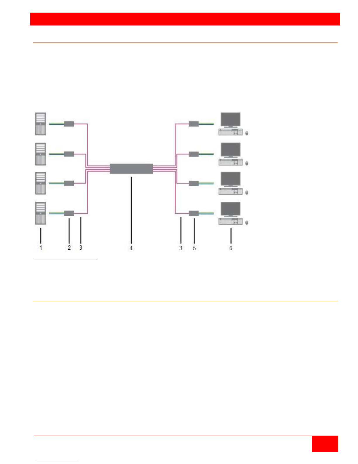
An Orion XC matrix system consists of an Orion XC matrix, one or more CPU Units, and one or more CON
Units. The Orion XC matrix is connected to the CPU Units / CON Units by CATx interconnect cables.
The CPU units are connected to the computers’ video, keyboard and mouse ports using standard video and
USB or PS/2 cables. CON Units are connected to console display, keyboard, mouse and USB peripherals.
The communication between the Orion XC matrix and the CPU Units / CON Units takes place over CATx
interconnect cables.
Figure 1. System Overview
1 - Source (computer, CPU)
3 – CATx Interconnect cables 4 - Orion XC matrix
5 - CON Units 6 -
2 - CPU Units
Console (monitor, keyboard, mouse)
Synchronized switching
The Orion XC unit can be set up to control the switching features of other Orion XC units. When the
master unit is switched to a selected CPU port, all other Orion XC units configured for synchronization will
also switch to that CPU port. The main unit is assigned a unique IP address compatible with the existing
network. The main unit is then connected to the network via a network cable. The master unit’s IP
address is entered into the secondary units that will be switched via the main unit.
Orion XC Installation and Operations Manual
5
Page 14
MODELS
Orion XC Model Descri pt ion
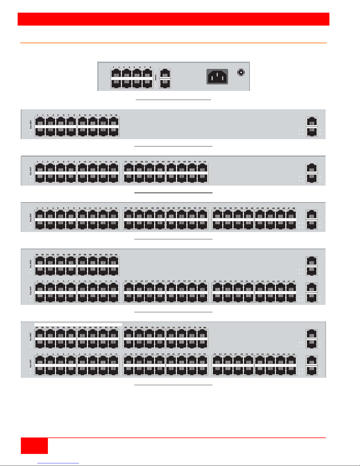
The following views of the Orion XC matrix illustrate the available chassis types.
Figure 2. Orion XC 8-port Model
Figure 3. Orion XC 16-port Model
Figure 4. Orion XC 32-port Model
Figure 5. Orion XC 48-port Model
Figure 6. Orion XC 64-port Model
Figure 7. Orion XC 80-port Model
6
Orion XC Installation and Operations Manual
Page 15

INSTALLATION
Installation
The installation section of this manual explains the basic System Setup. It then describes in detail how to
set up the Orion XC as a KV M Matrix, as well as how to stack and cascade Orion XC switches.
System Setup
First time users are recommended to connect all of the system components in the same room initially, as a
test setup. This will facilitate correcting any cabling problems, and simplify the system configuration
process.
Due to the construction of the matrix chassis it is recommended to use an additional sub-floor below the
matrix for the use in a 19“ rack.?????
Setup of the matrix
1. Connect a CON Unit to an I/O port of the matrix for its configuration.
2. Connect keyboard, mouse and monitor to the CON unit.
3. Connect the matrix and the CON unit to the power supply.
4. Display the OSD menu via 'Hot Key' and ‘o’, select Configuration, and login with administrator rights.
5. Configure according to application requirements .
6. Select Save in the Configuration menu, and then select Rest art Matrix.
7. Optional: Establish a network connection between the matrix and the Java tool in order to perform a
more extended configuration.
Setup of Extenders
1. Connect a CON unit to the matrix using CATx interconnect cables.
2. Connect the CON unit to the console devices (monitor, keyboard and mouse).
3. Connect the 5VDC power supply units to the CON unit and apply power.
4. Check the basic function of the CON unit by displaying the OSD menu via 'Hot Key' and ‘o'.
5. Connect the source (computer, CPU) to the CPU unit of the extender by using the provided connection
cables.
6. Connect the CPU unit to the matrix by using CATx interconnect cables.
7. If the system is set up as an SDI video matrix, connect the video source directly to the matrix by using
interconnect cables (coax, fiber).
8. Connect the 5VDC power supply units to the CPU units.
9. Start the system. ???? Apply power to the Matrix????
Possible Orion XC Setups
The Orion XC can be set up in a variety of ways to provide the optimum system environment.
A portion of the Orion XC can be configured as a Single-Head work station, a portion as Dual-Head or
Quad-Head, or even as a video matrix. The KVM and USB 2.0 can also be configured. ????
The Orion XC can be configured via OSD, using the keyboard connected to the CPU board????, or one
connected to an extender CON unit. It is also possible to configure it via the Java Tool.
The following sections show the typical installations of the Orion XC.
Orion XC Installation and Operations Manual
7
Page 16
KVM Matrix
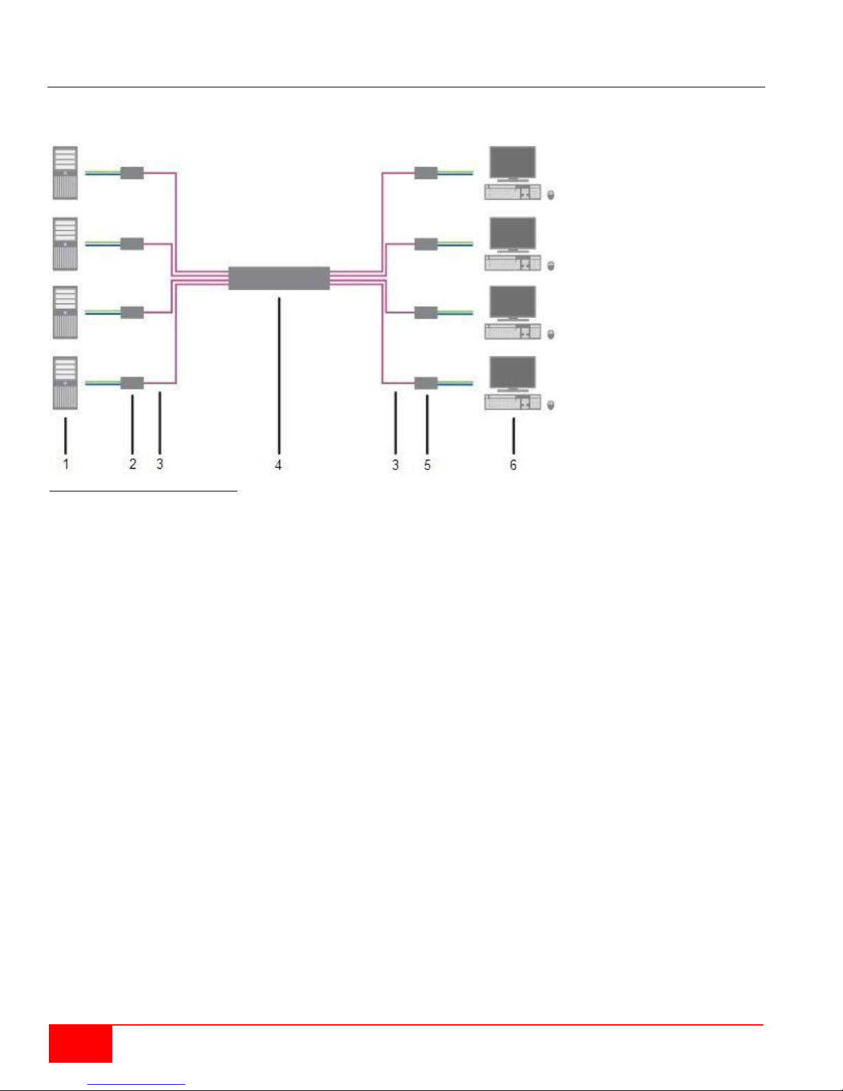
In Single-Head mode, up to 80 ports can be used either as input or as output ports depending on
components and equipment. At the same time there is non blocking access for all users, i.e. user access
is not limited by the activities of another user.
Figure 8. Single-Head KVM Matrix
1 - Source (com p ut er, C PU )
2 - CPU Units
3 - Interconnect cables 4 - Orion XC matrix
5 - CON Units 6 -
Console (monitor, keyboard, mouse)
If a Single-Head console is used, it is possible to also get access to a Dual-Head or Quad-Head console.
????However, control is only possible at monitor 1.
Video from a single source can be switched to any number of monitors simultaneously. Audio (optional)
can also be switched in the same manner.
8
Orion XC Installation and Operations Manual
Page 17
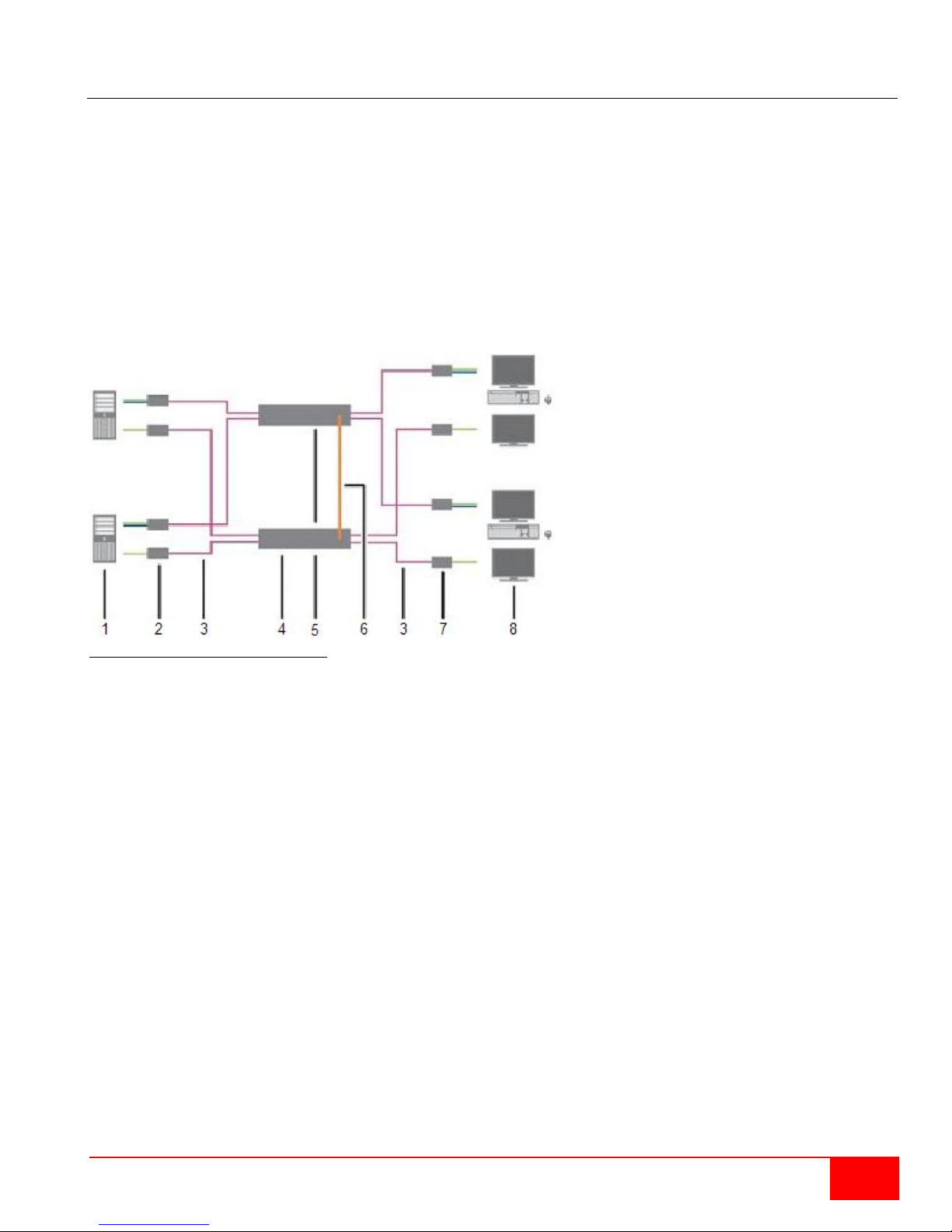
Parallel Operation (Stacking)
For special configurations, especially installations with more than one monitor per work station or
additional support of USB 2.0 transmission paths, the number of connectable CPUs and consoles can be
increased by a parallel operation (stacking) of several Orion XC devices.
One of the Orion XC matrices is configured as the master matrix. All the others must be configured as
slave matrix, with the IP address of the master matrix entered in the Master IP Address field. The slaves
must be connected to the master matrix via the network connector (RJ45) of the CPU board????, and the
Enable LAN Echi???? option must be activated at the master matrix.
If a switching command is executed in the OSD, the slave matrices will also switch automatically.
Switching of stacked devices might be delayed by several seconds.
Figure 9. Parallel Operation (Stacking)
1 - Dual-Head source (computer, CPU) 2 - CPU unit
3 - Interconnect cable 4 - Orion XC matrix (master matrix)
5 - Orion XC matrix (slave matrix) 6 - Network connection master / slave(s)
7 - CON unit 8 - Console (2x monitor, keyboard, mouse)
Orion XC Installation and Operations Manual
9
Page 18
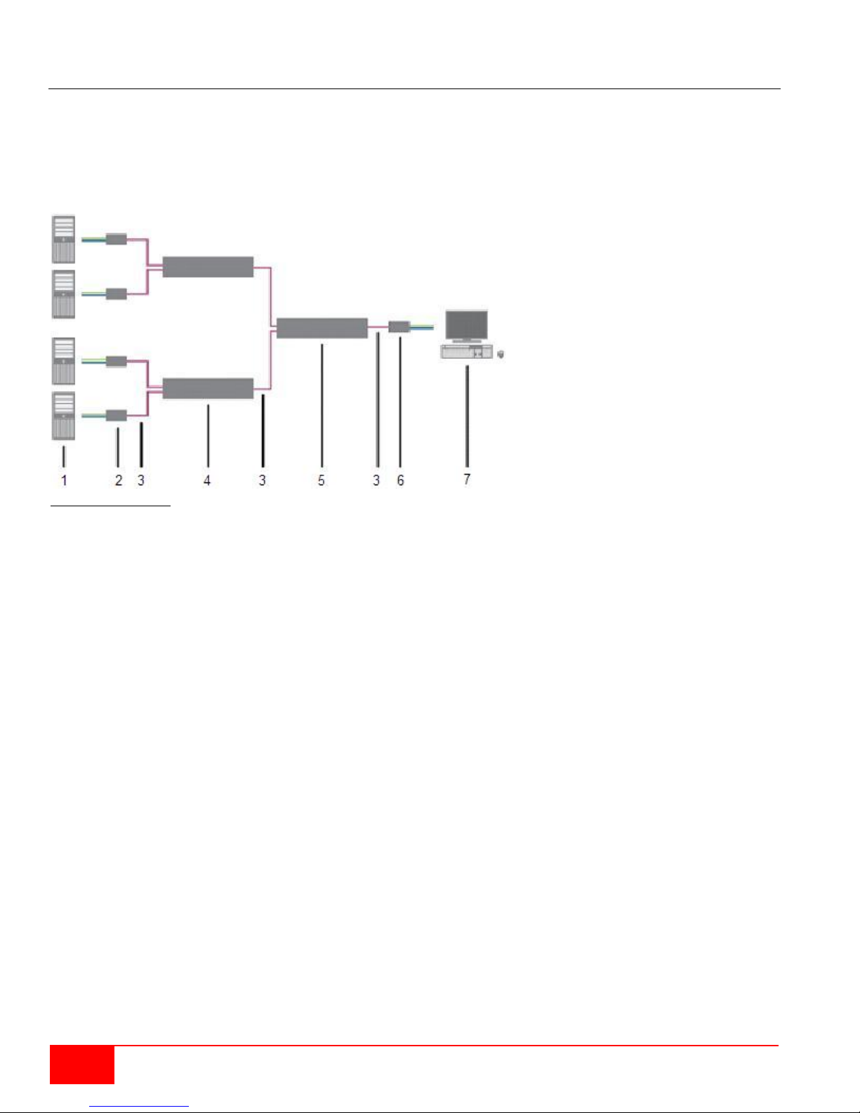
Cascading
For applications exceeding the number of available ports, the system can be extended by cascading.
In this case, the Orion XC devices are connected by so-called "tie lines". The tie lines are dynamically
configured to support connections in both directions.
To access cascaded matrices from a console, one of the matrices has to be configured as sub matrix.
Figure 10. Cascading
1 - Source (computer, CPU) 2 - CPU unit
3 - Interconnect cable 4 - Orion XC (sub matrix)
5 - Orion XC (main matrix) 6 - CON unit
7 - Console (monitor, keyboard, mouse)
10
Orion XC Installation and Operations Manual
Page 19

CONFIGURATION
Function
Keyboard Command
Enter Command Mode (default)
2x <Left Shift> (or 'Hot Key')
Exit Command Mode
<Esc>
Change 'Hot Key' sequence
<current 'Hot Key'> + <c>,
<new 'Hot Key' code>, <Enter>
'Hot Key' Code
'Hot Key'
0
Freely selectable
2
2x <Scroll>
3
2x <Left Shift>
4
2x <Left Ctrl>
5
2x <Left Alt>
6
2x <Right Shift>
7
2x <Right Ctrl>
8
2x <Right Alt>
Configuration
The Orion XC switch is easy t o configure. This can be done through keyboard commands in Command
Mode, invoking the On-Screen Display, or using the Java Tool. These options are described below.
Command Mode
The Orion XC has a Command Mode that allows several functions via keyboard command during normal
use.
To enter Command Mode use a 'Hot Key' sequence and to exit Command Mode, press <Esc>. While in
Command Mode, the LEDs Caps Lock and Scroll Lock on the console keyboard will flash repeatedly.
In Command Mode normal keyboard and mouse operation will cease. Only selected keyboard commands
are available.
If there is no keyboard command executed within 30 seconds after activating Command Mode, it will
automatically be deactivated.
The following table lists the keyboard commands to enter and to exit Command Mode, and to c hange the
'Hot Key' sequence:
<Key> + <Key> Press keys simultaneously
<Key>, <Key> Press keys successively
2x <Key> Press key quickly, twice in a row (similar to a mouse double-click)
The 'Hot Key' sequence to enter Command Mode can be changed. The following table lists the 'Hot Key'
Codes for the available key sequences.
Orion XC Installation and Operations Manual
11
Page 20

Set freely selectable 'Hot Key'
In order to set a freely selectable 'Hot Key' (e.g. 2x <Space>), use the following keyboard sequence:
<current 'Hot Key'>, <c>, <0>, <Space>, <Enter>
Reset 'Hot Key'
In order to set a 'Hot Key' back to default settings of the extender, press the key combination
<Right Shift> + <Del> within 5 seconds after switching on the CON unit or plugging in a keyboard.
Control Options
The Orion XC contains an internal CPU that allows control of all functions from any console without the
need for an external CPU.
The following methods are available to configure and/or operate the Orion XC:
through the OSD
through the Java Tool
through the serial interface
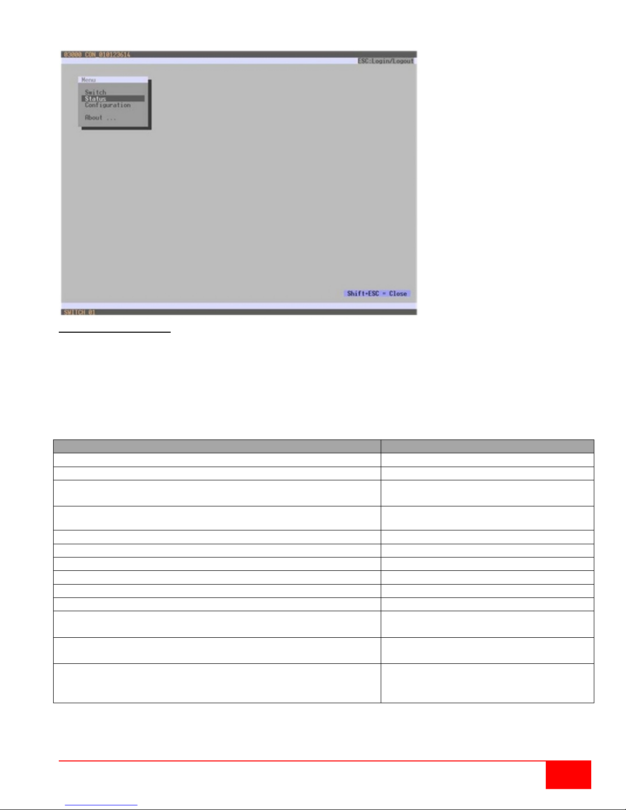
Control through the OSD
The Orion XC can be configured through the OSD (On-Screen-Display). The settings of the Configuration
menu are described below. All other menus are described in later chapters.
Entering the OSD
1. Start Command Mode with the 'Hot Key' (default: 2x <Left Shift>).
2. Press <o> to open OSD. A list of all available CPUs will be seen as a start menu.
3. Press <Esc> to enter the main menu.
Leaving the OSD
Press <Shift> + <E sc> simultaneously.
The OSD will be closed without any further changes and any currently active CPU connection will be
displayed.
12
Orion XC Installation and Operations Manual
Page 21
Function
Keyboard Command
Left cursor - only within an input field or a switching screen
<Cursor Left>
Right Cursor - only within an input field or a switching screen
<Cursor Right>
In input fields: Line up (with wrap around)
In menus: Line up (without wrap around)
<Cursor Up>
In input fields: Line down (with wrap around)
In menus: Line down (without wrap around)
<Cursor Down>
Previous page in menus with more than one page
<Page Up>
Next page in menus with more than one page
<Page Down>
Next input field
<Tab>
Previous input field
<Left Shift> + <Tab>
Next option in selection fields
<+>
Previous option in selection fields
<->
Switching in selection fields between two conditions, e.g.
between ON / OFF or Y (Yes) / N (No)
<Space>
In menus with input fields: Save data
In menus: Select menu item
<Enter>
In menus with input fields: Cancel data input without saving
level
<Esc>
Menu Structure
Figure 11. OSD Main Menu
The general layout of the OSD is structured into three areas:
Upper status area (topmost two text lines)
Worki ng area
Lower status area ( lowest two text lin es )
Keyboard control
The following keyboard commands are available.
In menus with selection fields: Go back to the higher menu
Orion XC Installation and Operations Manual
13
Page 22
Function
Keyboard Command
Sort ID numbers in a descending order or in an ascending
order by pressing the keyboard command twice (ID).
<F1>
Sort ID names in a descending order or in an ascending order
by pressing the keyboard command twice (Name).
<F2>
Go to the next result in the list of results of the search field
(Next).
<F3>
Go to the previous result in the list of results of the search field
(Previous).
<F4>
Refresh the currently shown list (Refresh).
<F5>
Jump between the search field and the list of results (Find).
<F6>
Field
Default Value
User
admin
Password
admin
Sorting Function
Lists and tables in the Java Tool offer a sorting function for fast and smooth search. The following sorting
functions are available:
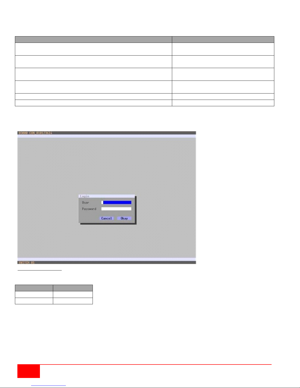
Password request
Access to the configuration menu requires administrator rights. User login is mandatory.
Figure 12. Login menu
For security reasons, please change the administrator password as soon as possible.
14
Orion XC Installation and Operations Manual
Page 23

Control through the Java Tool
Requirements
The following requirements have to be met to use the Java Tool:
Computer with an installed Java Environment (JRE, version 1.6 or higher)
Java Tool software
Available network connection between the Java Tool and the matrix
Contact your system administrator concerning JRE and network connection.
Installation of the Java Tool
The Java Tool is available as a single executable program file that does not require a separate installation.
Copy the tool after receiving the file to a directory on the computer.
If you have not received the Java Tool, contact Rose Electronics.
Computer Connection to the Matrix
For a connection between computer and matrix via your network, a standard network cable is required.
For a direct connection between computer and matrix, a crossover network cable is required.
Connect the appropriate network cable(s) between the RJ45 ports of the computer and the matrix.
Starting the Java Tool
Open the Java Tool by double clicking the program icon or use the keyboard <Enter> key.
Connecting to the Matrix
At least FTP rights are required.
1. Open the Java Tool.
2. Select Matrix > Connect in the menu bar.
3. Enter the IP address of the matrix in the popup input field according to the network configuration of the
Orion XC.
4. Enter the user name and password for the Orion XC.
5. Confirm the inputs with the OK button or reject with Cancel.
Orion XC Installation and Operations Manual
15
Page 24
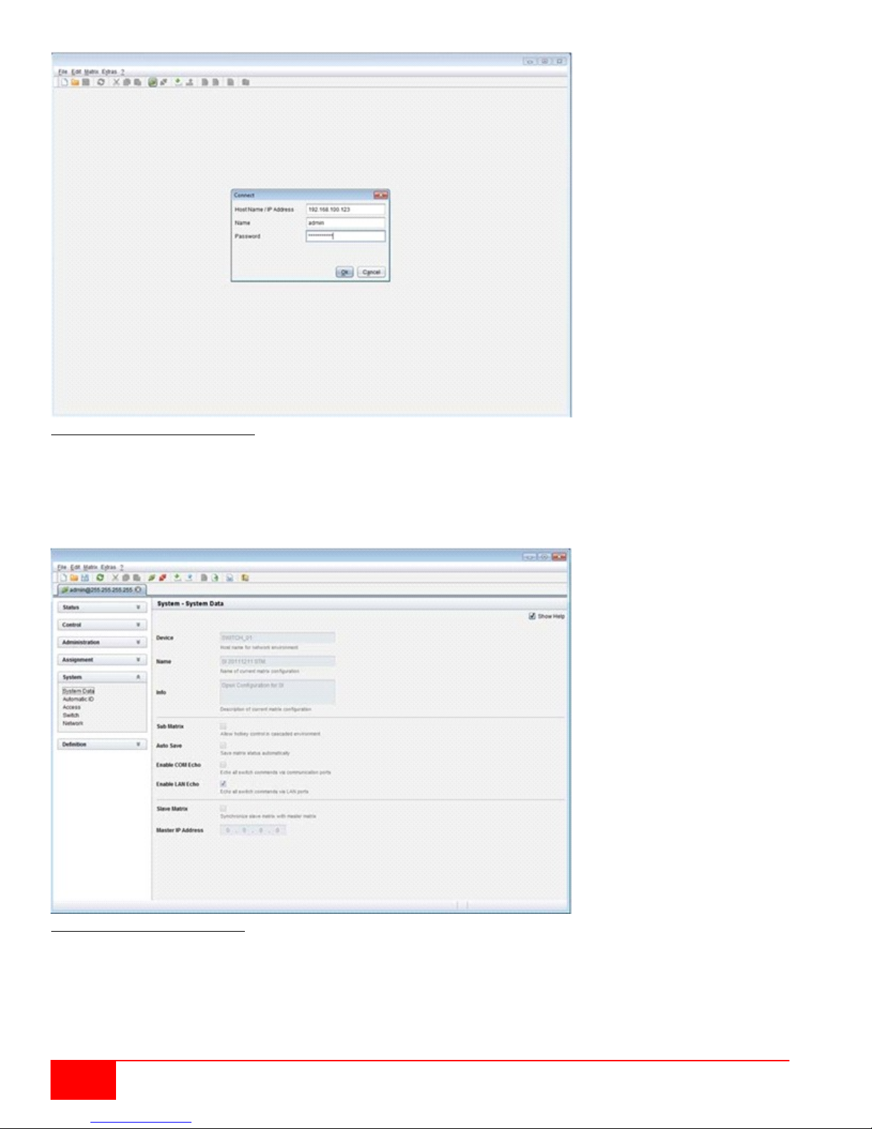
Figure 13. Java Tool Connect menu
No more than twelve connections between the matrix and the Java tool can be established at the same
time due to a limitation of available sockets.
Menu structure
Figure 14. Java Tool System Data
16
Orion XC Installation and Operations Manual
Page 25

The menu structure of the Java Tool is subdivided into various sections:
Function
Mouse Command
Menu selection, marking
Left mouse button
Open function specific selection menus
Double click left mouse button
Open context specific selection menus
Right mouse button
Function
Keyboard Command
Cursor to the left
<Cursor Left>
Cursor to the right
<Cursor Right>
Line up
<Cursor Up>
Line down
<Cursor Down>
Previous page in input or status menus with more than one page
<Page Up>
Next page in input or status menus with more than one page
<Page Down>
Next field in input menus
<Tab>
Previous field in input menus
<Left Shift> + <Tab>
Switching in selection fields between two conditions (checkmark or not).
Open already marked fields with editing or selecting possibility.
<Space>
In menus: Data saving
Menu item selection
<Enter>
Leave tables
Jump from tables into the next field
<Ctrl> + <Tab>
Leave tables
Jump from tables into the previous
field
<Ctrl> + <Left Shift> +<Tab>
Menu bar (top line)
Toolbar (second line)
Tab bar (third line)
Task area (left menu section)
Working area (right menu section)
Status bar (bottom section)
Operating Instructions
The operation of the Java Tool is intuitive and corresponds to the user interface of common operating
systems.
The integrated help texts in the working area of the Java Tool can be activated or deactivated by the
checkbox in the upper right corner.
Mouse Control
The following mouse commands are available
Keyboard Control
The following keyboard commands are available.
Various functions within the menus can be executed with keyboard commands listed to the right of the
respective menu item (e. g. press <Ctrl> + <S> to execute Save).
Orion XC Installation and Operations Manual
17
Page 26

Reload Options
The information shown in the Java Tool can be reloaded in different ways.
Via keyboard <F5>
Via Edit > Reload in the menu bar
Via the "Reload" symbol in the symbol bar
Context Function
The Java Tool offers several context functions that support a user friendly and effective operation. The
individual context functions are described in their respective chapters.
To execute a context function, click the right mouse button on the corresponding field and select the
desired function.
Sorting Function
Lists and tables in the Java Tool offer a sorting function for fast and smooth searching.
1. For ascending sort status, click the left mouse button once on the header of the column to be sorted.
The sort status is indicated by an arrow that points upwards.
2. For descending sort, click the left mouse button twice on the header of the column that has to be
sorted. The sort is displayed by an arrow that points downwards.
3. To cancel the sort, click left mouse button once or twice on the header of the column that is sorted
until the displayed arrow disappears.
Filter Function
Lists and tables in the Java Tool also offer a filter function that facilitates searching.
1. To activate a filter, click the right mouse button on the header of the column to be filtered and select
Set Filter.
2. With the keyboard, enter into the header the word or part of a word to be used as a filter. The filter
results are shown immediately.
3. To delete a filter, click the right mouse button on the header of the column that has a filter and select
Clear Filter.
An active filter is indicated by an asterisk in the header. The filter function is similar to that used in common
web search engines.
Offline Configuration
Configuration and system settings can be changed via the Java Tool in offline mode when there is not a
direct connection between the tool and Orion XC.
To activate a configuration in the matrix, proceed as follows:
1. Select File > Upload in the menu bar.
2. Enter the IP address of the matrix, the name and password of the authorized user, and select the
storage location of the new configuration (default, or config01 - config08) in the Select
Configuration menu.
3. Select Matrix > Connect in the menu bar and enter the IP address of the matrix and the name and
password of the authorized user.
4. Select Administration > Activate Configuration in the task area and select the storage location
that has been selected above.
5. Use the Activate button to open the selected configuration within the matrix. The connection and
the open tab will be closed and the matrix will be restarted.
During the activation of a configuration, the matrix is temporarily unavailable.
18
Orion XC Installation and Operations Manual
Page 27
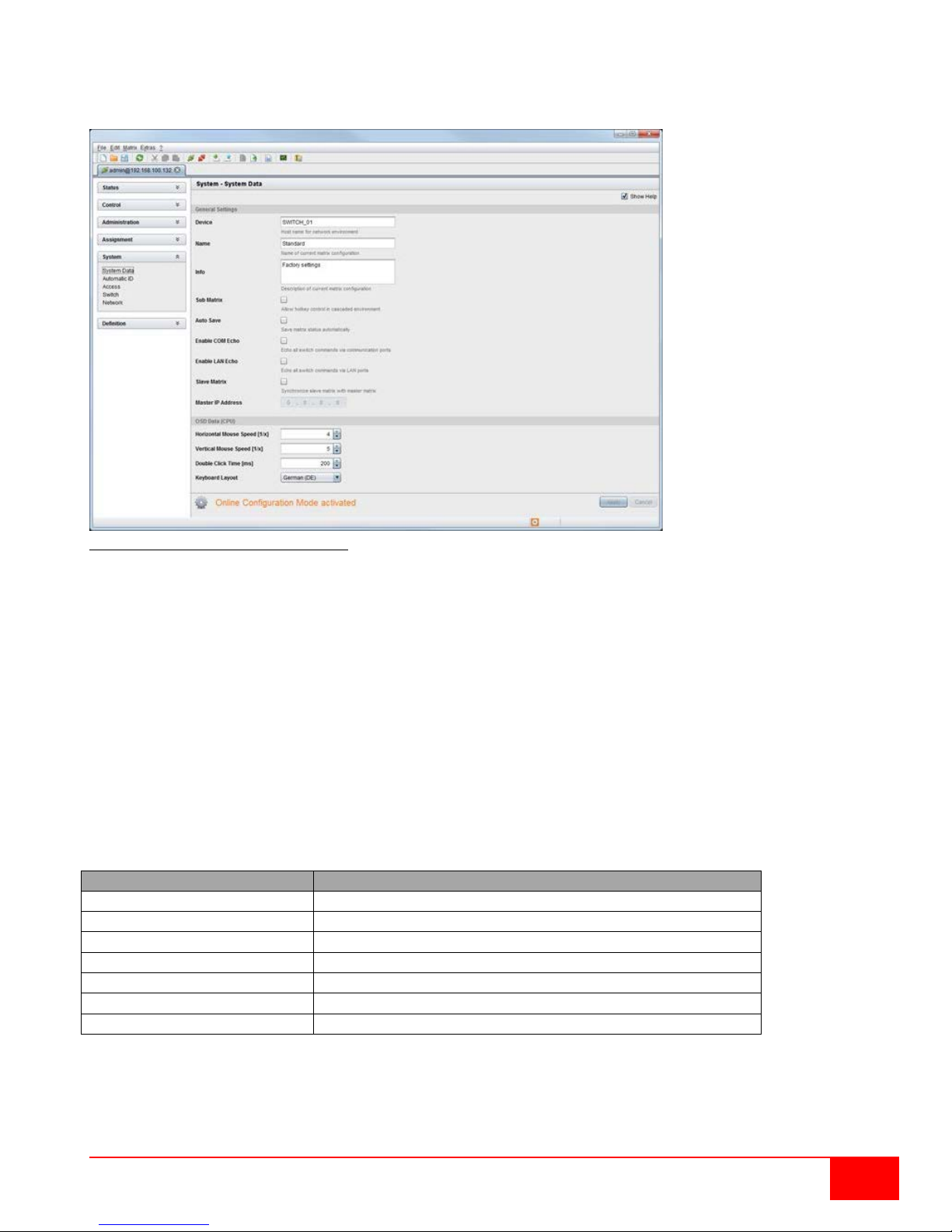
Online Configuration
Option
Description
IP / Hostname
Default IP address of the matrix required for connection
User
Default user name required for connection
Configuration Directory
Default directory for configuration files
Firmware Directory
Default directory for update files
Status Directory
Default directory for the firmware status
Import / Export Directory
Default directory for import and export files
Presets Directory
Default directory for macro files
Configurations and system settings can be also edited via Java tool in online mode with an active
connection between matrix and Java tool.
Figure 15. Java Tool Online Configuration
To edit a configuration in online mode, proceed as follows:
1. Select the Matrix > Activate Online Configuration Mode menu item. This setting will be
additionally shown in the lower part of the working area.
2. Make any edits at the configuration and system settings and confirm by clicking on the Apply
button. The changes will be immediately applied.
3. In order to deactivate the online mode, select the Matrix > Deactivate Online Configuration
Mode menu item in the menu bar.
Options menu
The Java tool can be adapted and customized by setting up various default settings.
To activate or change the default settings , proceed as follows:
Select Extras > Options in the menu bar. The Default Settings tab will open.
The following default settings can be changed:
To set font sizes for the Java tool, proceed as follows:
1. Select Extras > Options in the menu bar.
2. Open the Font tab.
3. Select the desired font size (normal or large).
Orion XC Installation and Operations Manual
19
Page 28
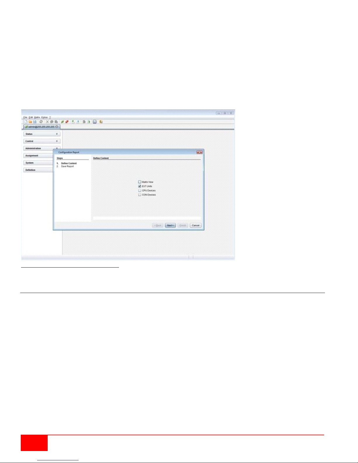
Report
The Java tool is equipped with a report function that exports the current switching status and all relevant
parts of the matrix configuration to a PDF file. The report function can be used in both online or offline
mode of the Java tool.
To create a report, proceed as follows:
1. Select File > Report... in the menu bar. A selection assistant will be opened.
2. Select those contents that should be included in the report (Matrix View, EXT Units, CPU Devices
and CON Devices) and confirm with the Next > button.
3. Select the preferred location for storage of the report and confirm with the Finish button. The report
will be created as a PDF file.
Figure 16. Java Tool Configuration Report
Control through the Serial Interface
The Orion XC operating system has a number of functions that can be controlled via serial interface. There
are telegrams for switching single or all connections available, both unidirectional and bidirectional. In
addition, there are telegrams for an overall definition of the total switching status and for saving and loading
such switching states.
By request, the Orion XC can provide an echo through the serial interface or network interface of all
switching operations. This allows tracking of the current connection status of the matrix at any time.
As an additional application, Orion XC clones can be switched as slaves (Stacking) in parallel via serial or
network interface.
20
Orion XC Installation and Operations Manual
Page 29
Assignment
The Orion XC offers the possibility of a console specific or a CPU specific assignment.
The first possibility is to assign virtual CPUs to real CPUs.
The second possibility is to assign real consoles to virtual consoles.
Virtual CPU
Virtual CPUs can be assigned to real CPUs in this menu.
This simplifies the process of switching several consoles to the same CPU. If there are several consoles
connected to a virtual CPU which is assigned to a real CPU, the real CPU needs to be changed just once,
and all consoles will receive the video signal of the new CPU.
This can be done through the OSD or the Java Tool.
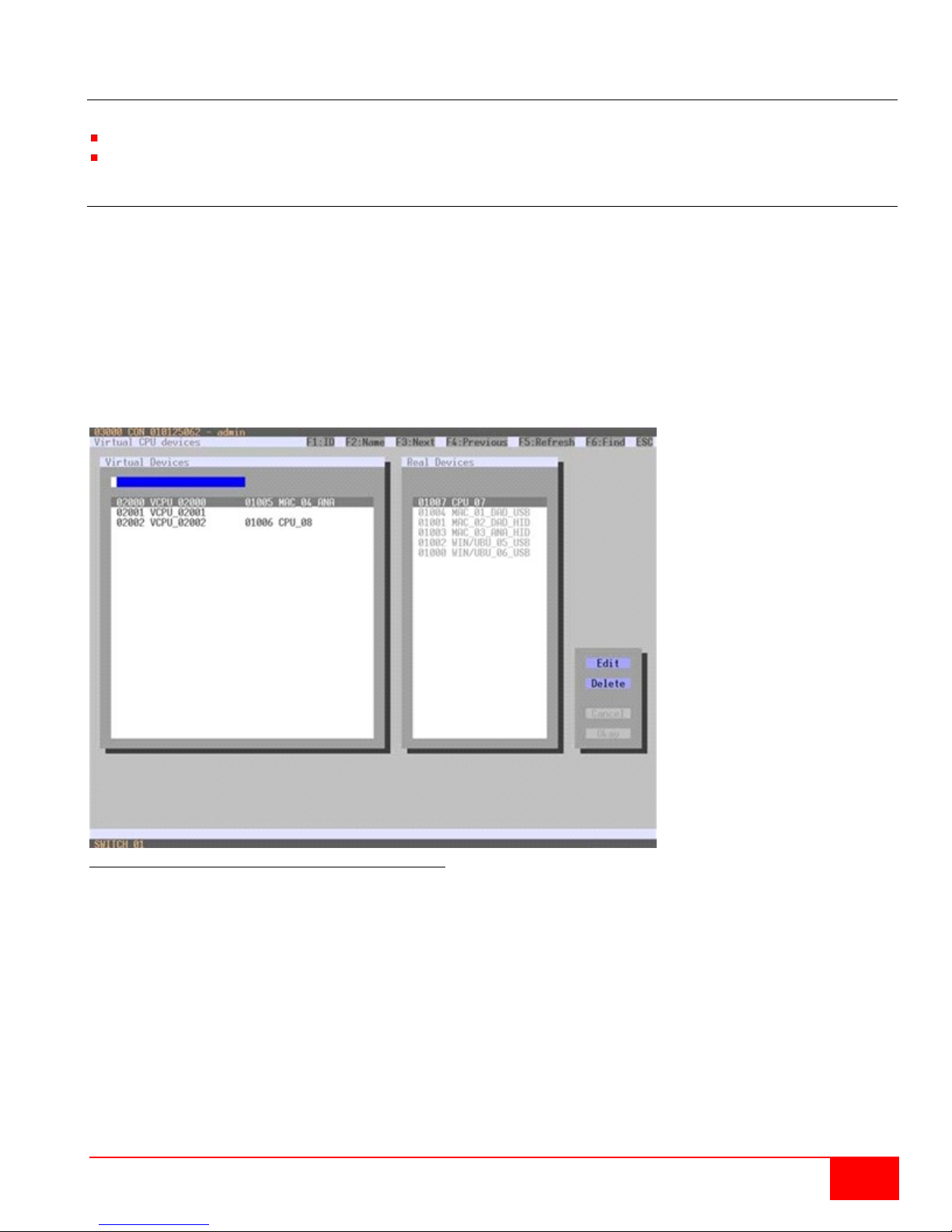
Assignment through OSD
Select Assignments > Virtual CPU devices in the main menu.
Figure 17. Virtual CPU Devices Assignment through OSD
To make an assignment, proceed as follows:
1. Select the virtual CPU in the Virtual Devices list that is to be assigned to a real CPU.
2. Press the Edit button.
3. Select the CPU in the Real Devices list that is to be assigned to the selected virtual CPU.
4. Press the Okay button to confirm the assignment.
Only one virtual CPU can be assigned to a real CPU.
Orion XC Installation and Operations Manual
21
Page 30
Button
Function
Send
Send assignments to the matrix
Reload
Reload changes
Assignment through Java Tool
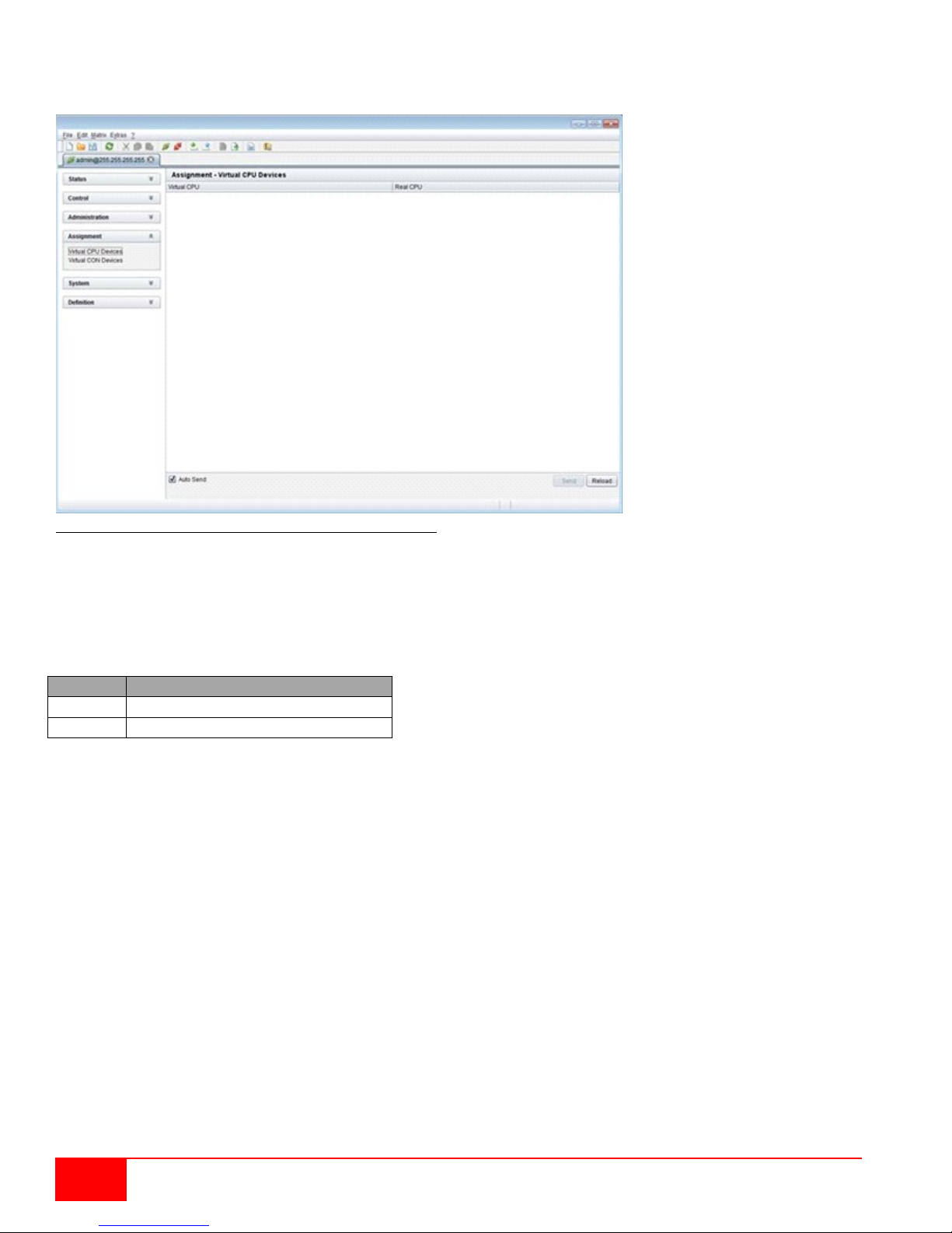
Select Assignment > Virtual to Real CPU in the task area.
Figure 18. Virtual to Real CPU Assignment through Java Tool
To mak e an assignment, proceed as follows:
1. Select a virtual CPU in the Virtual CPU list.
2. Double click in the Real CPU column to get a list of all available real CP Us.
3. Select a real CPU.
Select between the following buttons:
By activating the Auto Send function in the left lower corner of the working area, switching operations will
be done immediately without confirmation by pressing the Send button.
The selection boxes in the Real CPU column contain a filter function for an easy selection of single
consoles from a larger group of consoles.
The Java tool additionally offers the possibility to go directly from the Assignment menu to the Definition
menu to check specific settings for the respective CPU.
Use the right mouse button to select the CPU and select Open CPU Device.
22
Orion XC Installation and Operations Manual
Page 31
Virtual Console
Real consoles can be assigned to virtual consoles in this menu.
This simplifies the process of setting and changing access permissions by changing the permissions of the
virtual console and then applying them to all assigned real consoles.
Virtual consoles can be switched exactly in the same way as real consoles. If a virtual console is switched
to a CPU, all real consoles that are assigned to the virtual console will receive the video signal. The last real
console that is scheduled in the l ist of assignments wi ll additiona lly receive keyboard and mouse control.
This can be done through the OSD or the Java Tool.
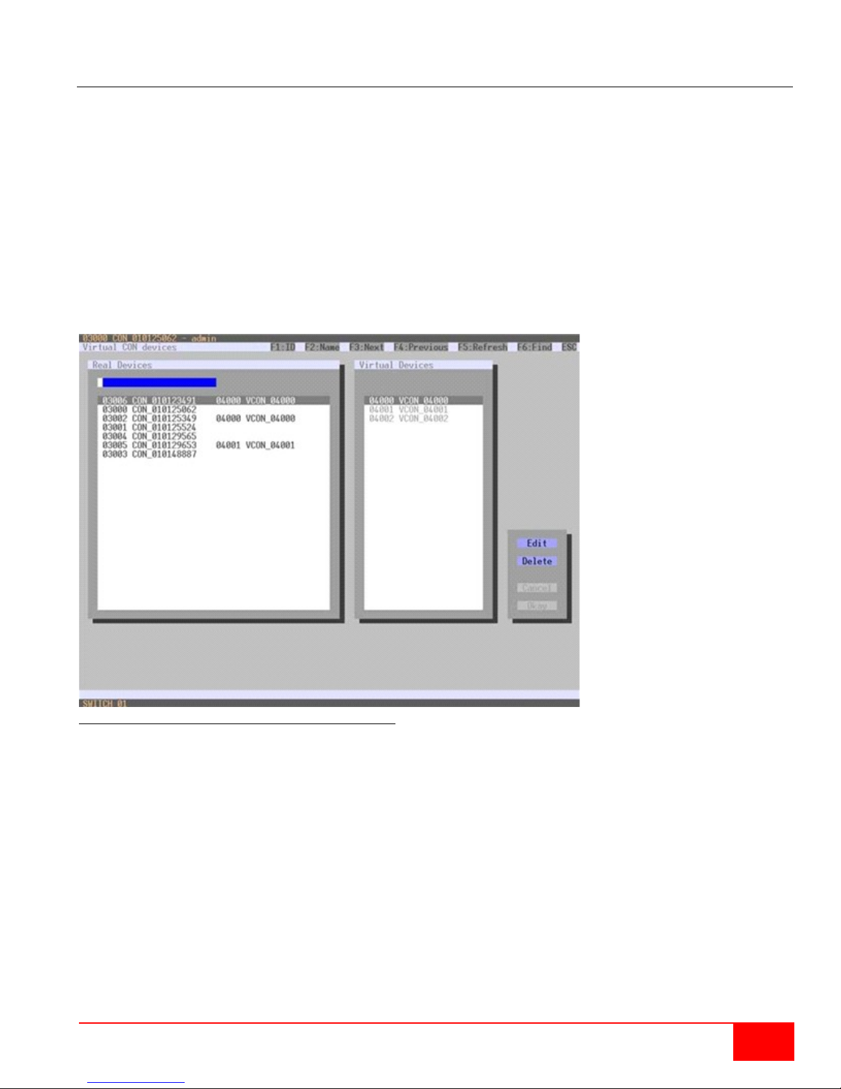
Assignment through OSD
Select Assignments > Virtual CON devices in the main menu.
Figure 19. Virtual CON Devices Assignment through OSD
To mak e an assignment, proceed as follows:
1. Select the real console in the Real Devices list that is to be assigned to a virtual CPU.
2. Press the Edit button.
3. Select the virtual co nsole in the Virtual Devices list that is to be assigned to the selected real
console.
4. Press the Okay button to confirm the assignment. The assignment will be done.
A virtual console can be assigned to more than one real consoles.
Orion XC Installation and Operations Manual
23
Page 32
Button
Function
Send
Send assignments to the matrix
Cancel
Reject changes
Assignment through Java Tool
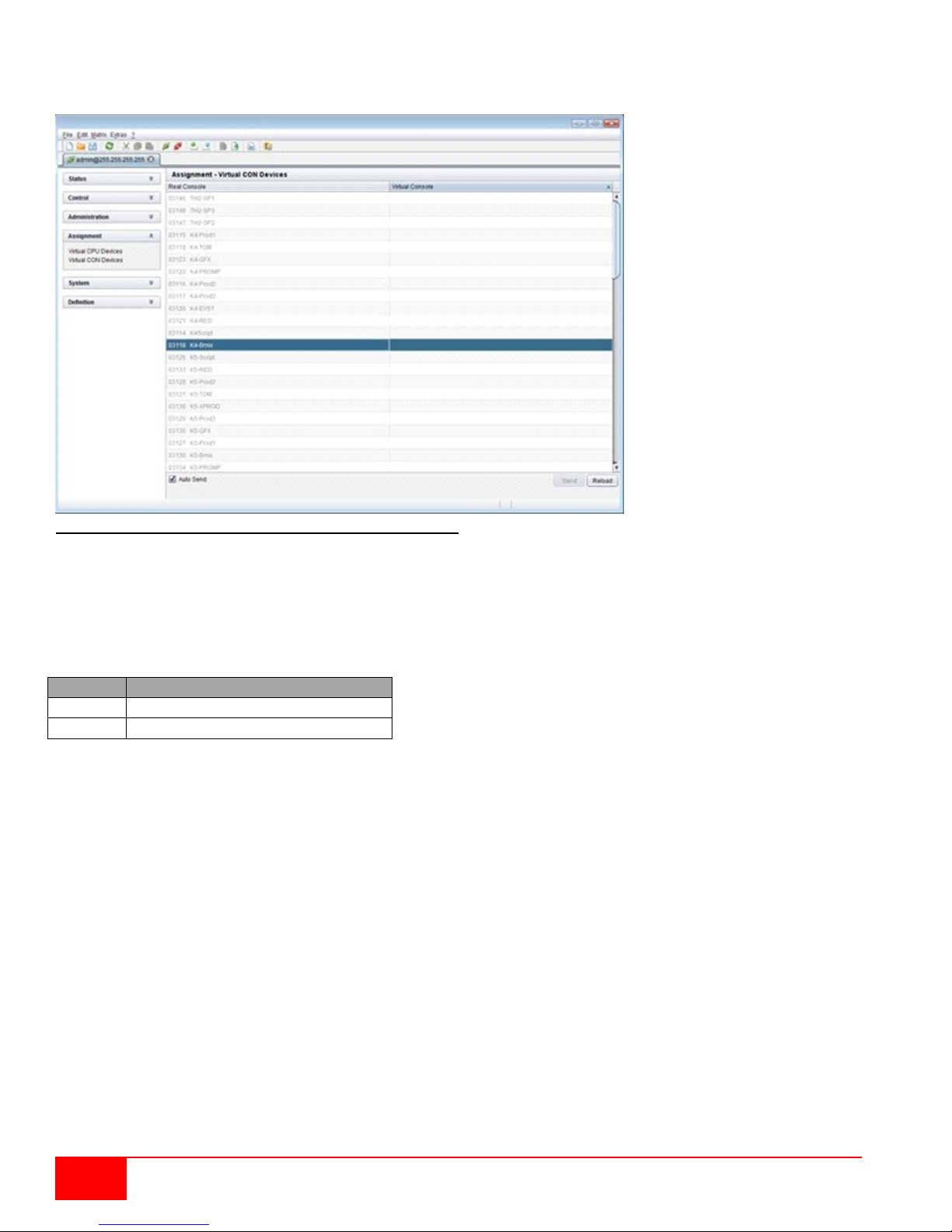
Select Assignment > Real to Virtual Console in the task area.
Figure 20. Virtual to Real Console Assignment through Java Tool
To make an assignment, proceed as follows:
1. Selec t the r equired real cons ole in the Real Console table.
2. Double click in the Virtual Console column to get a list of all available virtual consoles.
3. Select the required virtual console.
Select between the following buttons:
By activating the Auto Send function in the left lower corner of the working area, switching operations will
be done immediately without confirmation by pressing the Send button.
The selection boxes in the Virtual Console column contain a filter function for an easy selection of single
CPU from a group of CPUs.
The Java tool additionally offers the possibility to go directly from the Assignment menu to the Definition
menu to check specific settings for the respective console.
Use the right mouse button to select the respective console and select Open CON Device.
24
Orion XC Installation and Operations Manual
Page 33

Field
Selection
Description
Device
Text
Enter the device name of the matrix (default: SWITCH_01)
Name
Text
Enter the name of the configuration that is used to save the
current settings (default: Standard)
Info
Text
Additional text field to describe the configuration (default:
Factory settings)
Sub Matrix
Activated
If the matrix is defined as a sub matrix in the OSD, the user will
sub matrix.
Deactivated
Function not active (default)
Aut o Sa ve
Activated
Save the current configuration of the matrix in the flash memory
executed in the meantime.
Deactivated
Function not active (default)
Enable COM Echo
Activated
Send all performed switching commands in the matrix as an
controller via serial interface.
Deactivated
Function not active (default)
Enable LAN Echo
Activated
Send all performed switching commands in the matrix as an
controller via LAN connection.
Deactivated
Function not active (default)
Slave Matrix
Activated
Synchronize the slave matrix according to the switch status of
the master matri x.
Deactivated
Function not active (default)
Master IP Address
Numerical value
Set the network address of the master matrix (default value:
000.000.000.000)
Hor. Mouse Speed
1/x
1-9
Adjustment of the horizontal mouse speed, 1 = slow, 9 = fast
(default value: 4)
Ver. Mouse Speed
1/x
1-9
Adjustment of the vertical mouse speed, 1 = slow, 9 = fast
(default value: 5)
Double Click Time
100-800
Adjustment of the time slot for a double click (default value:
200 ms)
Keyboard layout
Region
Set the OSD keyboard layout according to the used keyboard
System Settings
System settings can be set up and modified on the Orion XC. The configuration of the system settings can
only be done by users with administrator rights.
System Data
The system configuration is set up here. This can be done through either the OSD or the Java Tool.
The following settings can be modified.
lose control automatically. Control can be recovered by using
the keyboard command <Shift>, <Shift>, <s>, <o>. The OSD
now will be opened again in the matrix that has been defined as
periodically.
Note: During saving of the configuration, the matrix will not be
operational. Saving takes place every 600 seconds, as long as
changes of the configuration or switching operations have been
echo via serial interface.
Note: This function should be enabled when using a media
echo via LAN connection.
Note: This function should be enabled when using a media
Orion XC Installation and Operations Manual
25
Page 34
Button
Function
Cancel
Reject changes
Save
Save changes
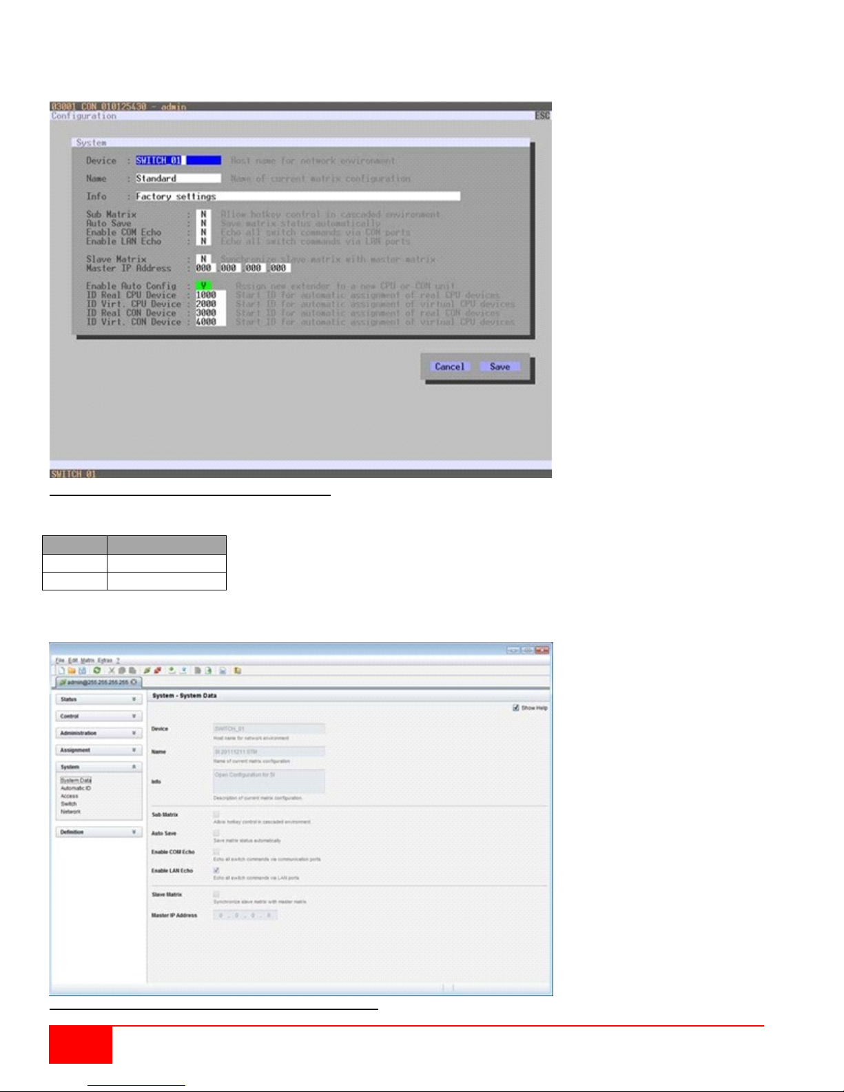
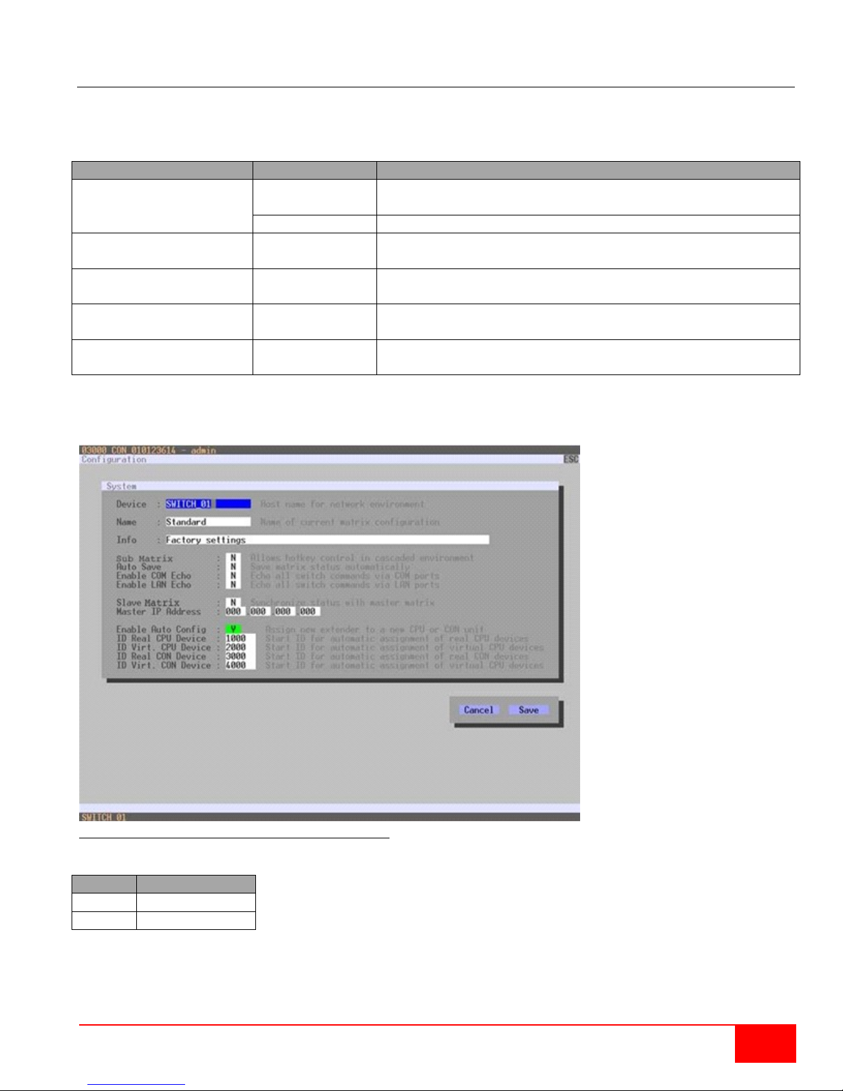
Modifying System Data through OSD
Select Configuration > System in the main menu.
Figure 21. Modifying System Settings through OSD
Select between the following buttons:
Modifying System Data through the Java Tool
Figure 22. Modifying System Settings through the Java Tool
26
Orion XC Installation and Operations Manual
Page 35
Field
Selection
Description
Enable Auto Config
Activated
Automatic creation of a new CPU or CON device when new
extender units are connected (default)
Deactivated
Function not active
ID Real CPU Device
Numerical value
Initial value of the automatic ID for real CPUs (default value:
1000)
ID Virtual CPU Device
Numerical value
Initial value of the automatic ID for virtual CPUs (default
value: 2000)
ID Real CON Device
Numerical value
Initial value of the automatic ID for real CONs (default value:
3000)
ID Virtual CON Device
Numerical value
Initial value of the automatic ID for virtual CONs (default
value: 4000)
Button
Function
Cancel
Reject changes
Save
Save changes
Automatic ID
The settings for automatic creation of CPU and CON devices when a new extender unit is connected are
handled in this menu. This menu can be accessed in the OSD and the Java Tool.
The following settings can be modified.
Modifying Automatic ID Settings through the OSD
Select Configuration > System in the main menu.
Figure 23, Modifying Automatic ID Settings through OSD
Select between the following buttons:
Orion XC Installation and Operations Manual
27
Page 36
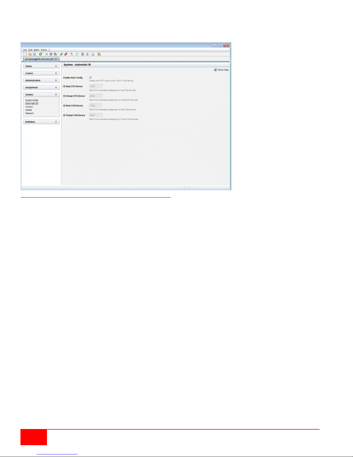
Modifying Automatic ID Settings through the Java Tool
Select System > Automatic ID in the task area.
Figure 24. Modifying Automatic ID Settings through the Java Tool
28
Orion XC Installation and Operations Manual
Page 37

Access Control
Field
Selection
Description
Force User Login
Activated
Users must login with a user name and a password once to
favorites and console macros still remain active.
Deactivated
Function not active (default)
Enable User ACL
Activated
CPU access is restricted according to the permissions in the
Switching by keyboard 'Hot Keys' requires a prior login.
Deactivated
Function not active (default)
Enable Console ACL
Activated
CPU access is restricted according to the permissions in the
required.
Deactivated
Function not active (default)
Enable new User
Activated
Newly created users automatically receive access to all CPUs.
Deactivated
Function not active (default)
Enable new CON
Activated
Newly created CON devices automatically receive access to
all CPUs.
Deactivated
Function not active (default)
Auto Disconnect
Activated
Upon opening the OSD, the console will be automatically
disconnected from the current CPU.
Deactivated
Function not active (default)
OSD Timeout
0-999 seconds
Period of inactivity after which OSD will be closed
Select 0 seconds, for no timeout (default: 0 seconds)
Auto Logout
0-999 minutes
Period of inactivity of a logged-in user at a console after which
(default: 0 minutes)
The access control configuration is set in this menu. This menu can be accessed in the OSD and the Java
Tool.
The following settings can be modified.
enter OSD. Thereafter the user remains logged in until he
explicitly logs out or an auto logout is effected.
Note: When using the Force User Login function, console
ACL (Access Control List).
User login is required.
respective Console ACL (Access Control List). No login
automatically.
he will be automatically logged out at this console.
There might be a disconnect because of the logout, depending
on the defined rights in each CON and user ACL.
Select 0 minutes for an automatic user logout when leaving
OSD.
Using the setting -1 allows the user to be logged in
permanently, until a manual logout is executed.
The timer is not active as long as the OSD is open.
Orion XC Installation and Operations Manual
29
Page 38
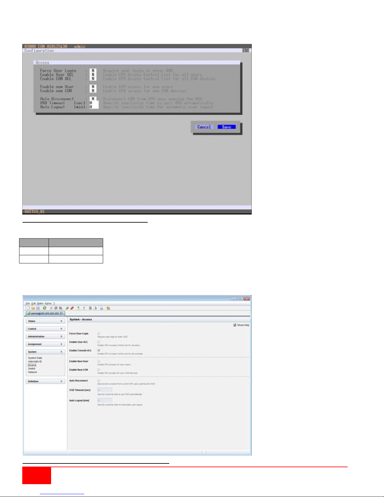
Button
Function
Cancel
Reject changes
Save
Save changes
Modifying Access Control through the OSD
Select Configuration > Access in the main menu.
Figure 25. Modifying Access Control through OSD
Select between the following buttons:
Modifying Access Control through the Java Tool
Select System > Access in the task area.
Figure 26. Modifying Access Control through the Java Tool
30
Orion XC Installation and Operations Manual
Page 39

Switch Settings
Field
Selection
Description
Video Sharing
Activated
The user can switch to any CPU as an observer, even to such ones
observer to the CPU that is connected to his console.
Deactivated
Function not active (default)
Force Connect
Activated
The user can connect to every single CPU as an operator, even to
To share K/M control, Force Connect has to be activated.
Deactivated
Function not active (default)
Force
Activated
An extension of Force Connect: If the user connects to a CPU as an
deactivated.
Deactivated
Function not active (default)
CPU Auto
Activated
If a console is not connected to a CPU, an automatic connection to
mouse button.
Deactivated
Function not active (default)
CPU Timeout
0-999
minutes
Period of inactivity after which a console will be automatically
disconnected from its current CPU (default value: 0 minutes)
Keyboard
Connect
Activated
Activate request for K/M control by keyboard event (key will be lost)
Deactivated
Function not active (default)
Mouse Connect
Activated
Activate request for K/M control by mouse event
Deactivated
Function not active (default)
Release Time
0-999
Period of inactivity of a connected console after which K/M control
CPU have a video only status (default value: 10 seconds)
The configuration of the switching parameters is set in this menu. This menu can be accessed in the OSD
and the Java Tool.
The following settings can be modified.
that are already assigned to another user (observer without
keyboard/mouse access).
Note: Switching is done with the <Space> key, not <Enter>.
The operator will not be informed if further users connect as an
such ones that are already assigned to another user.
Note: The previous user is set to video only status.
Disconnect
operator that is already assigned to another user, the connection to
the previous user will be completely disconnected.
Note: To share K/M control Force Disconnect has to be
Connect
seconds
the next available CPU can be established by hitting any key or
can be requested by other consoles connected to the CPU.
Note: Set "0" for an immediate transfer in real-time.
Only one console can have keyboard and mouse control at the
same time. The other consoles that are connected to the same
If the Keyboard Connect and/or Mouse Connect options are activated, the Release Time number of
seconds will have to elapse before a new user can gain control.
Orion XC Installation and Operations Manual
31
Page 40
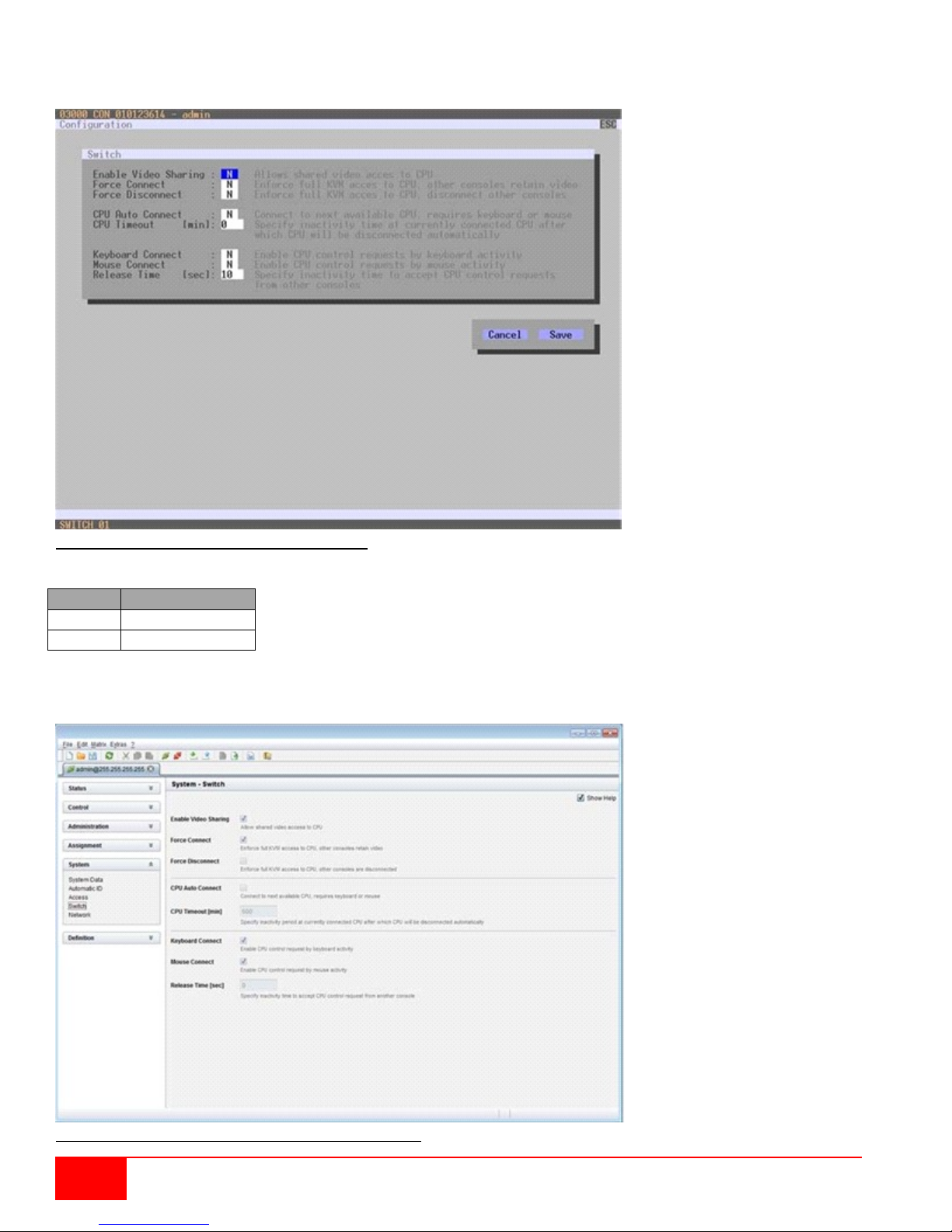
Button
Function
Cancel
Reject changes
Save
Save changes
Modifying Switch Settings through the OSD
Select Configuration > Switch in the main menu.
Figure 27. Modifying Switch Settings through OSD
Select between the following buttons:
Modifying Switch Settings through the Java Tool
Select System > Switch in the task area.
Figure 28. Modifying Switch Settings through the Java Tool
32
Orion XC Installation and Operations Manual
Page 41

Field
Selection
Description
DHCP
Activated
The network settings are automatically supplied by a DNS server
(default)
Deactivated
Function not active
IP address
Byte
Input the IP address in the form "192.168.1.1", if DHCP is not active
Subnet Mask
Byte
Input the subnet mask in the form "255.255.255.0", if DHCP is not active
(default: 255.255.255.0)
Gateway
Byte
Input the gateway address in the form "192.168.1.1", if DHCP is not
active
API Service
Activated
LAN interface at the Service activated for access via Java tool (API
service port 5555)
Deactivated
Function not active
FTP Server
Activated
FTP server for transmission of configuration files activated.
Deactivated
Function not active
HTTP Server
Activated
HTTP server activated (not yet implemented)
Deactivated
Function not active
Telnet Server
Activated
Telnet server activated (not yet implemented)
Deactivated
Function not active
SNMP Agent
Activated
SNMP agent for matrix monitoring active (not yet implemented)
Deactivated
Function not active
Syslog
Activated
Syslog server for status request is active
Deactivated
Function not active (default)
Syslog Server
Byte
Input of the IP address of the Syslog servers in the form “192.168.1.1”
Trace
DEB
Activate debug messages in Trace (default: Yes)
INF
Activate information messages in Trace (default: Yes)
NOT
Activate notification messages in Trace (default: Yes)
WAR
Activate warning messages in Trace (default: Yes)
ERR
Activate error me ssa ges in Trace (default: Yes)
Syslog
DEB
Activate debug messages in Syslog (default: Yes)
INF
Activate information messages in Syslog (default: Yes)
NOT
Activate notification messages in Syslog (default: Yes)
WAR
Activate warning messages in Syslog (default: Yes)
ERR
Activate error messages in Syslog (default: Yes)
Network
The network configuration is set in this menu. This menu can be accessed in the OSD and the Java Tool.
The following settings can be modified.
Activate the modified network parameters by doing a restart.
Note: Consult your system administrator before modifying the network parameters. Otherwise unexpected
results may occur, including failures with the network.
Orion XC Installation and Operations Manual
33
Page 42
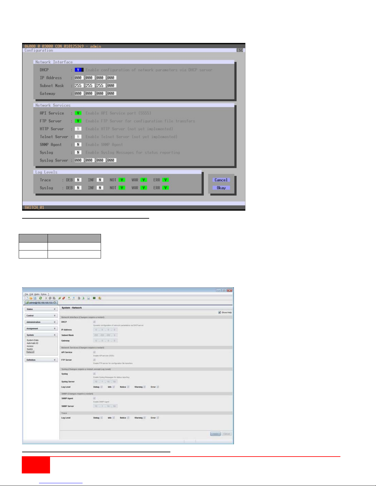
Modifying Network Settings through the OSD
Button
Function
Cancel
Reject changes
Save
Save changes
Select Configuration > Network in the main menu.
Figure 29. Modifying Network Settings through OSD
Select between the following buttons:
Modifying Network Settings through the Java Tool
Select System > Network in the task area.
Figure 30. Modifying Network Settings through the Java Tool
34
Orion XC Installation and Operations Manual
Page 43
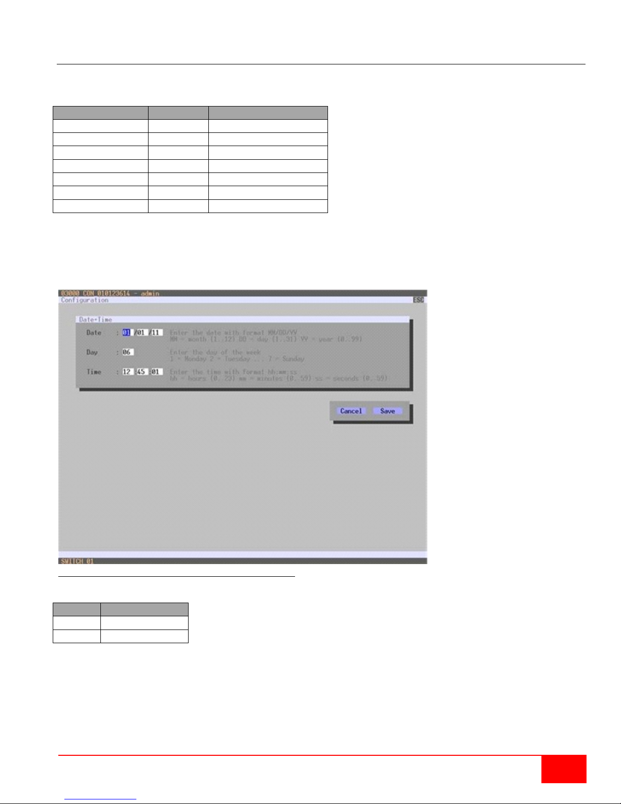
Field
Selection
Description
Month
1-12
Enter month
Date
1-31
Enter date
Year
1-99
Enter year
Day of the week
1-7
Enter day of the week
Hours
0-23
Enter hour
Minutes
0-59
Enter minute
Seconds
0-59
Enter second
Button
Function
Cancel
Reject changes
Save
Save changes
Date and Time
The Date and Time on the Orion XC are set in this menu. This menu can only be accessed in the OSD.
The following settings can be modified.
Note: Date format according to the English notation.
Modifying Switch Settings through the OSD
Select Configuration > Date+Time in the main menu.
Figure 31. Modifying Date and Time Settings through OSD
Select between the following buttons:
Orion XC Installation and Operations Manual
35
Page 44

User Settings
Field
Selection
Description
Name
Text
User name (case sensitive)
Password
Text
User password (case sensitive)
Repeat Password
Text
Repeat user password (case sensitive)
HTTP
Activated
Access permission via HTTP.
Deactivated
Function not active (default).
FTP
Activated
Access permission via FTP. This setting is necessary for access from
the Java tool or any web browser.
Deactivated
Function not active (default).
Telnet Access
Activated
Access permission via Telnet.
Deactivated
Function not active (default).
Power User
Activated
User has user rights
according to the CON or User ACL
Deactivated
Function not active.
Super User
Activated
Permission to switch any console to any CPU in Extended
Switching.
Deactivated
Function not active.
Administrator
activated
Permission for system configuration and all switching operations
This setting is required for an online connection with the Java tool
deactivated
Function not active.
The following user settings can be set up and modified on the Orion XC.
User
This menu is used to create new users and set up their access rights. This menu can be accessed in the
OSD and the Java Tool.
The following settings can be modified.
Permission to switch consoles to CPUs in Extended Switching
User has administrator rights
36
Orion XC Installation and Operations Manual
Page 45
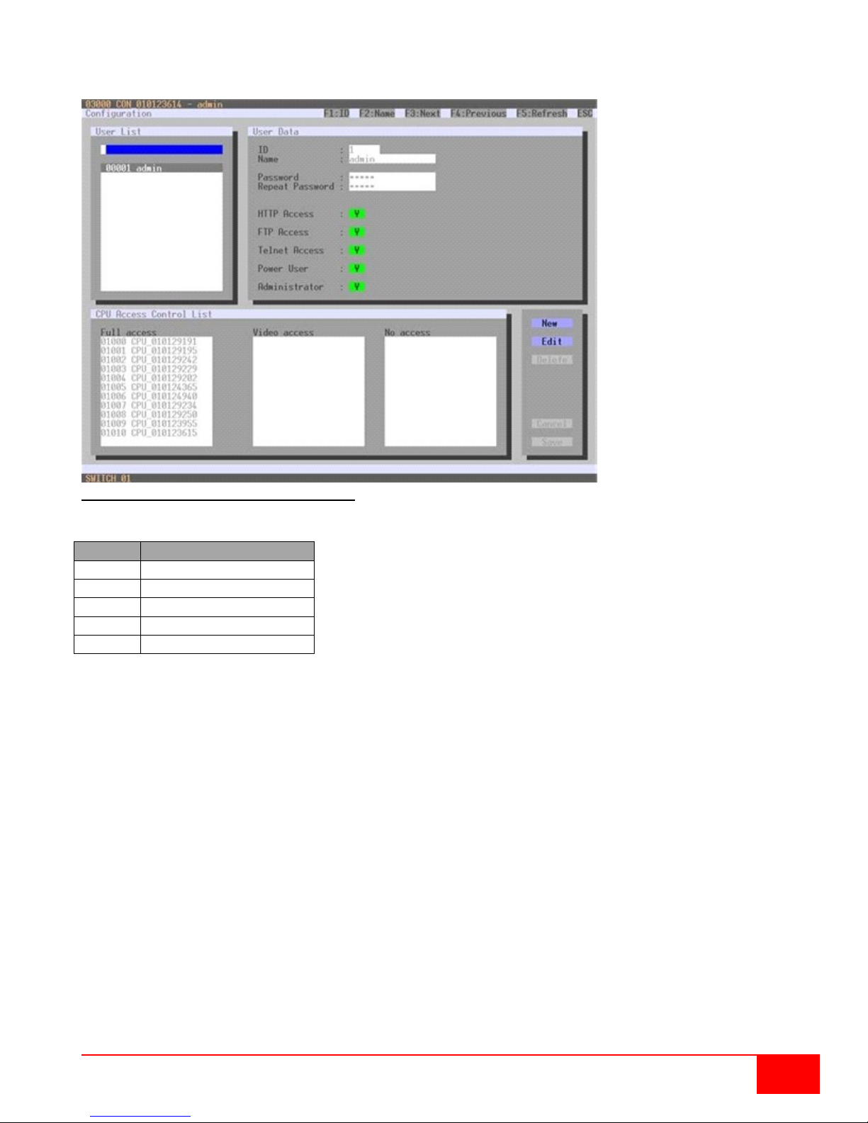
Button
Function
New
Create a new user
Edit
Edit an existing user
Delete
Delete an existing user
Cancel
Reject changes
Save
Save Changes
Modifying User Settings through the OSD
Select Configuration > User in the main menu.
Figure 32. Modifying User Settings through OSD
Select between the following buttons:
Orion XC Installation and Operations Manual
37
Page 46
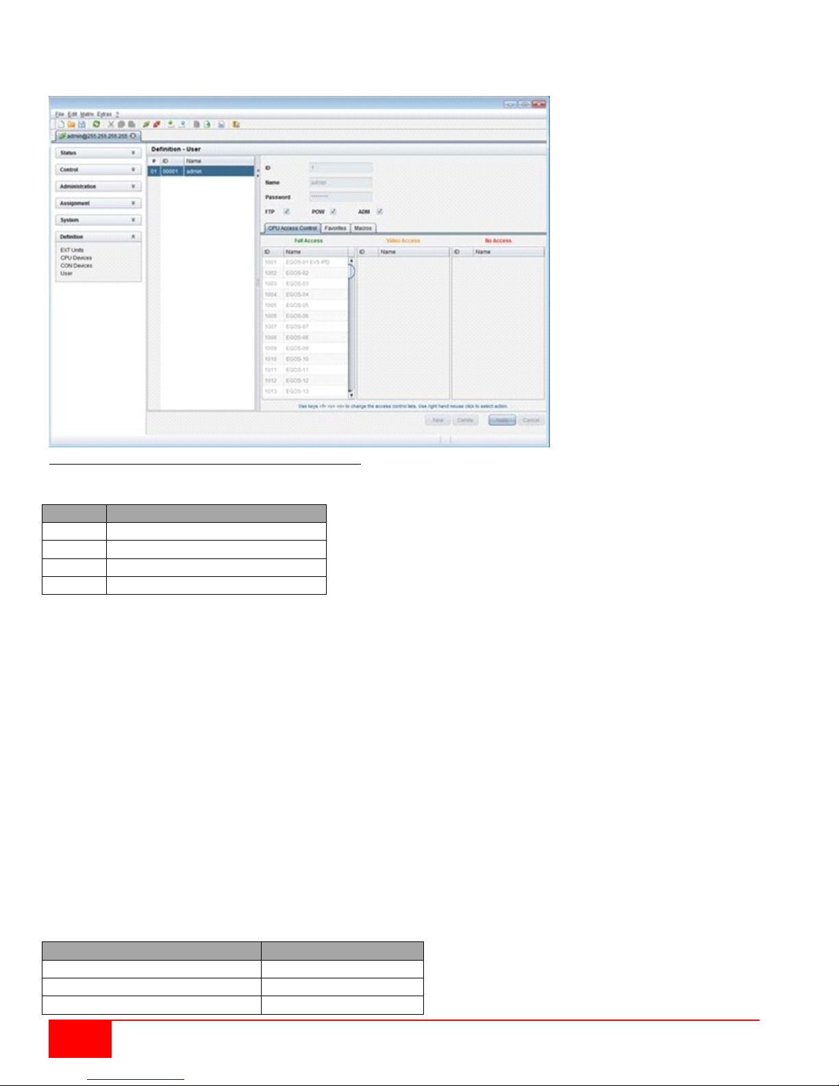
Button
Function
New
Open a new user configuration
Delete
Delete an existing user
Apply
Create a new user account
Cancel
Reject changes
Function
Keyboard Command
Add CPU to list Full Access
<F>
Add CPU to list Video Access
<V>
Add CPU to list No Access
<N>
Modifying User Settings through the Java Tool
Select Definition > User in the task area.
Figure 33. Modifying User Settings through the Java Tool
Select between the following buttons:
To configure user access rights for CPUs, proceed as follows:
1. Select a user in the User list.
2. By using the right mouse button once on a CPU in one of the respective access lists (Full Access,
Video Access and No Access), two lists for selection will appear in which the respective CPU can
be moved and the access rights can be changed.
3. Confirm the configuration wi t h the Apply button.
To create a new user, proceed as follows:
1. Press the New button.
2. Select a template of an existing user if applicable (Choose template).
3. Press the OK button.
4. Set a user name.
5. Set a password.
6. Set general access permissions.
7. Set user permissions for CPU access (paste function).
8. Set user favorites for OSD access.
9. Press the Apply button to save the new user settings.
Select between the following keyboard commands
38
Orion XC Installation and Operations Manual
Page 47
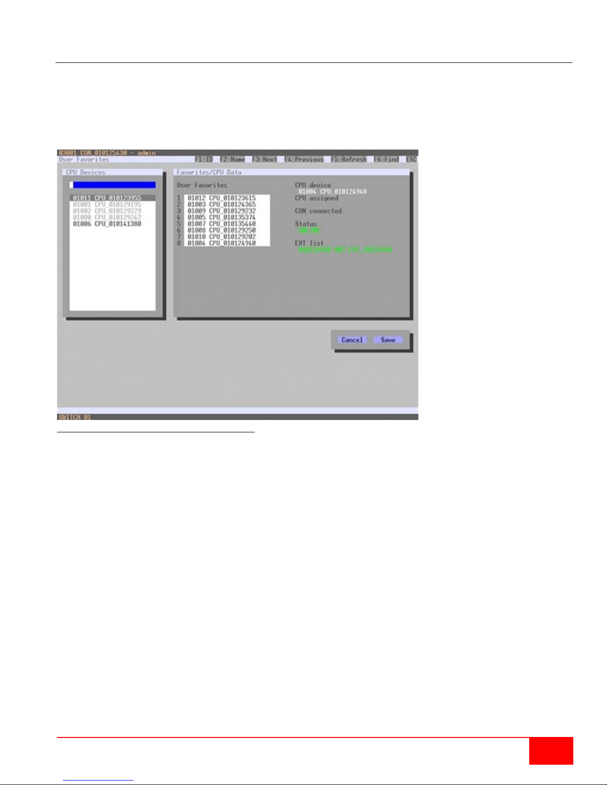
Favorite List Users
This menu is used to create individual favorite lists of CPUs that have to be switched frequently for
different users. A favorite list can contain up to eight different CPUs. The switching of the favorites is done
via 'Hot Key' using the keyboard. This menu can be accessed in the OSD and the Java Tool.
Setting up User Favorites through the OSD
Select Assignments > User Favorites in the main menu.
Figure 34. Setting up User Favorites through OSD
To create a favorite list for a user, proceed as follows:
1. Select successively those CPUs from the CPU Devices list that have to be moved to the favorite
list. By pressing the <a> key, a CPU device will be moved to the favorite list and it will be removed
by pressing <r>.
2. The order of the CPU devices within the favorite list can be changed by pressing the keys <+> and
<->.
3. Press the Save button to save the settings.
Orion XC Installation and Operations Manual
39
Page 48
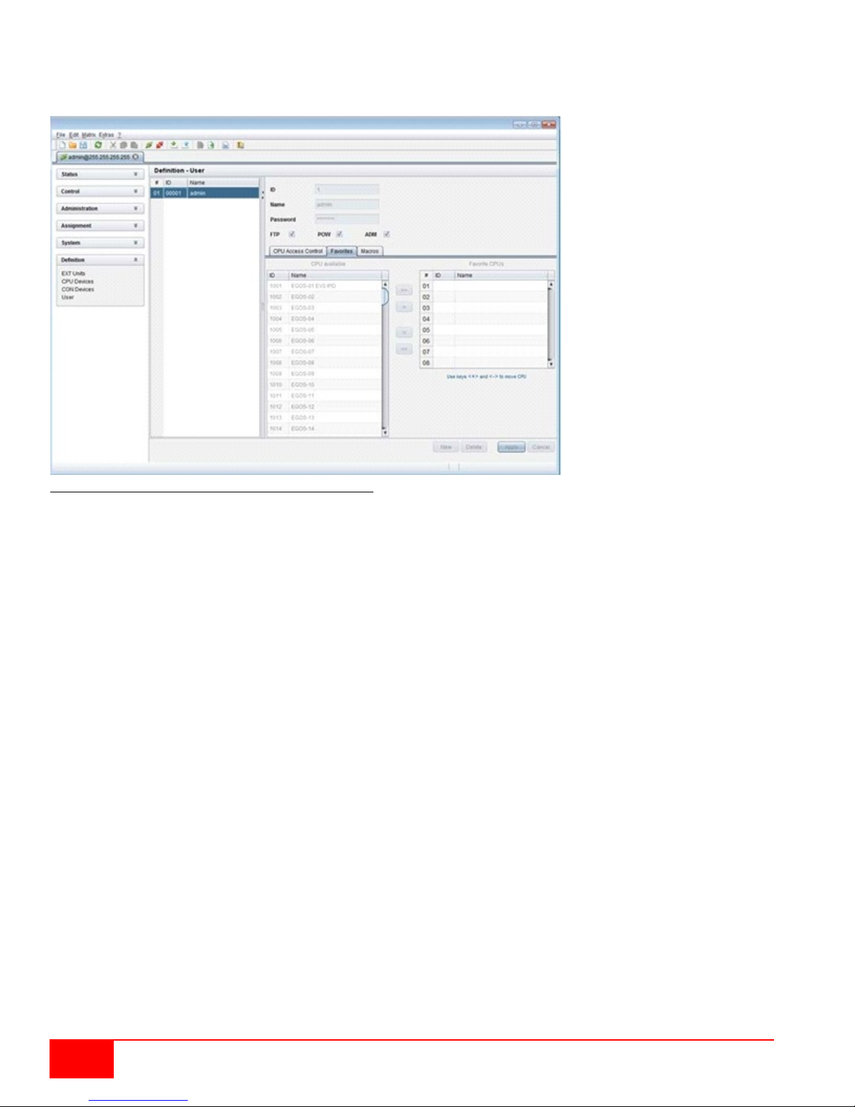
Setting up User Favorites through the Java Tool
Select the respective user in the working area of the User menu for the favorite list and open the
Favorites tab.
Figure 35.Setting up User Favorites through the Java Tool
To create a favorites list for any user, proceed as follows:
1. Select the CPUs in the CPU available list that should be added to the favorites list (CPU
assigned). Press and hold the <Ctrl> key to select more than one CPU device at a time.
2. Press the > button to move the selected CPU devices to the favorites list. If the >> button is
pressed, the firs t ei ght CPU devices in the CPU available list will be moved to the favorites list
(CPU assigned).
3. The position of a selected CPU device within the favorites list can be changed by pressing the <+>
and <-> keys.
4. To remove marked CPU devices from the favorites list, press the < button. If the << button is
pressed, all CPU devices will be removed from the favorites list.
40
Orion XC Installation and Operations Manual
Page 49

Field
Selection
Description
Function
Connect (P1=CON, P2=CPU)
Set bidirectional connection from console P1 to
CPU P2
Connect Video (P1=CON, P2= CPU)
Set video connection from console P1 to CPU
P2
Disconnect (P1=CON)
Disconnect console P1
Logout User
Logout current user
Set Real CPU (P1=VCPU, P2=RCPU)
Assign a virtual CPU to a real CPU
Set Virtual CON (P1=RCON, P2=VCON)
Assign a real console to a virtual console
Push (P1=CON)
The user’s current KVM connection is
video only connection.
Push Video (P1=CON)
The video signal of the user’s current
unchanged (KVM or video only).
Get (P1=CON)
The user’s console gets a KVM connection to
into a video only connection.
Get Video (P1=CON)
The user’s console gets a video only
only).
P1
CON or CPU Device
Name of CON or CPU device
P2
CON or CPU Device
Name of CON or CPU device
User Macros
This menu is used to set up macro commands for switching, disconnection or user administration. This
menu can be accessed in the OSD and the Java Tool.
The macro commands are created for each user separately. A macro can execute up to 16 switching
commands successively. The execution of the macros is done via 'Hot Key' and the function keys <F1> to
<F16>.
Note: In order to execute user macros the user has to be logged in to the matrix.
Select between the following settings:
(01-16)
forwarded to console P1 and is changed to a
connection (KVM or video only) is forwarded to
console P1. The user’s connection remains
the CPU that is currently connected to console
P1. The connection of console P1 is changed
connection to the CPU that is currently
connected to console P1. The connection of
console P1 remains unchanged (KVM or video
Orion XC Installation and Operations Manual
41
Page 50
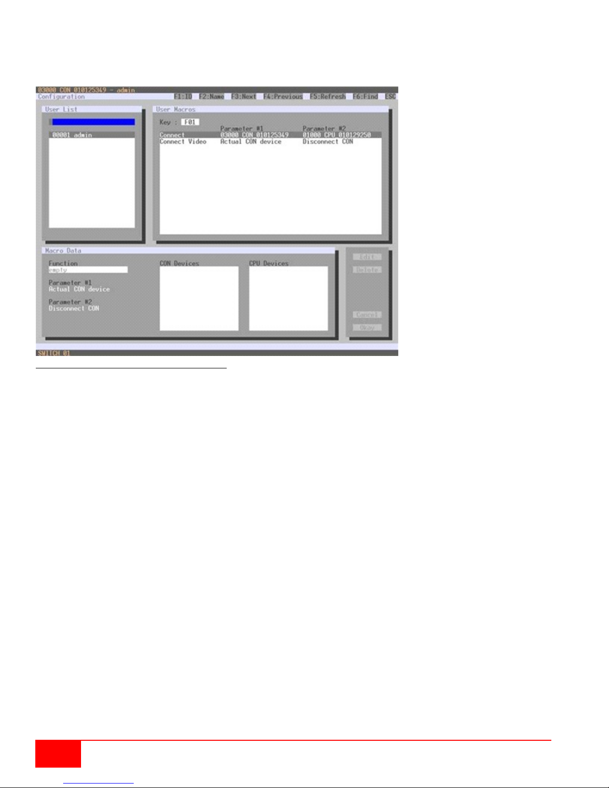
Setting up User Macros through the OSD
Select via Configuration > User Macros in the main menu the user for whom a macro is to be
created.
Figure 36. Setting up User Macros through OSD
To create a macro for the selected user, proceed as follows:
1. Select in the Key field the F key (F1 to F16) to which a macro is to be assigned.
2. Select the appropriate position for the new action in the list of actions currently assigned to the key.
3. Select for the marked location in the list a macro command in the Macro Data field.
4. Set the necessary parameters P1 and P2 (e.g. CON Devices or CPU Devices) for the selected
macro command.
5. Confirm the inputs by pressing the <Enter> key and repeat the process for further macro
commands, if necessary.
42
Orion XC Installation and Operations Manual
Page 51
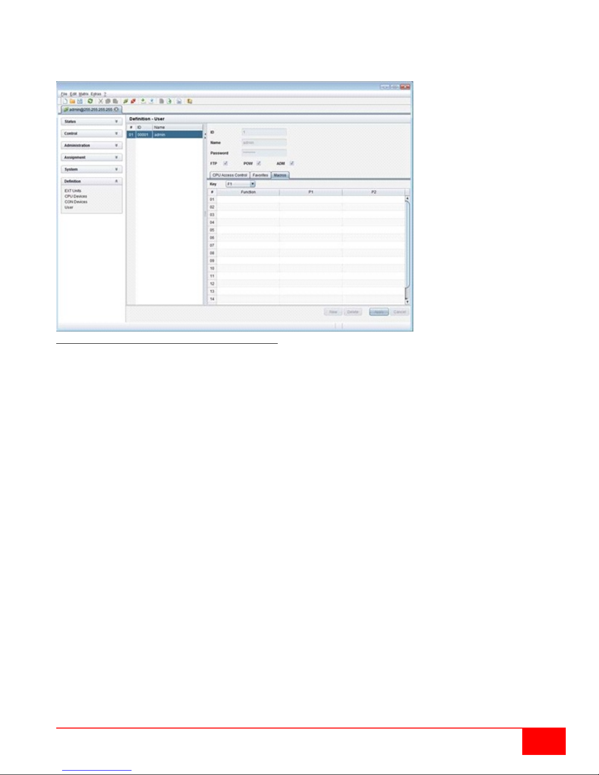
Setting up User Macros through the Java Tool
Select in the working area of menu Definition > User the user for which macros are to be created and
open the Macros tab.
Figure 37. Setting up User Macros through the Java Tool
To cre ate a macro for the s electe d user, proceed as follows:
1. Select in the Key field the F key (F1 to F16) to which a macro is to be assigned.
2. Select in the Function column the commands that should be part of the macro. The selection list is
opened by a double click on the empty fields.
3. Select in the P1 and P2 columns the respective parameters for the macro functions (e.g.
corresponding consoles and CPUs).
4. Confirm the inputs by pressing the Apply button.
For an efficient macro configuration the following context functions are available:
By right clicking on the Macros tab, macros can be assigned to other users using the Assign Macros
to ... function, and can be copied from other users by using the Copy Macros from ... function.
By right clicking on the macro list, all the macro commands of the selected key can be copied into the
cache by using the Copy Key Macros function. These macros can then be pasted from the cache into
another key by using the Paste Key Macros function. All macros of a selected key can be reset by
using the Reset Key Macros function.
Orion XC Installation and Operations Manual
43
Page 52
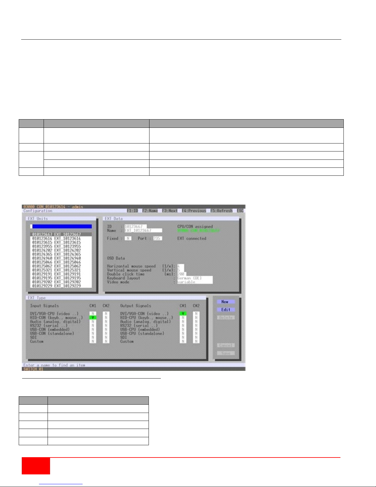
Field
Selection
Description
ID
Text
Numerical value of the extender ID (KVM Extenders: ID is
provided by extender unit (Serial No.) and cannot be changed)
Name
Text
Name of the extender unit
Fixed
Activated
Create an extender unit with a fixed port assignment (default)
Deactivated
Function not active.
Port
1-288 (depending on the matrix)
Port number of the extender unit
Button
Function
New
Create a new extender unit
Edit
Edit an existing extender unit
Delete
Delete an existing extender unit
Cancel
Reject changes
Save
Save Changes
Extender Settings
All extender units are managed in this menu. This menu also allows the creation of new ext ender units and
the deletio n of existing extender units. This menu can be accessed in the OSD and the Java Tool.
The extender unit describes the connection of an physical extender to the matrix. Every extender board
with a direct cable connection to the matrix is recognized as an extender unit. Dual-Head KVM extenders
will be recognized as two independent extender units.
KVM Extenders automatically create extender units inside the matrix.
Select between the following settings:
Managing Extender Settings through the OSD
Select Configuration > EXT Units in the main menu.
Figure 38. Managing Extender Settings through the OSD
Select between the following buttons:
44
Orion XC Installation and Operations Manual
Page 53
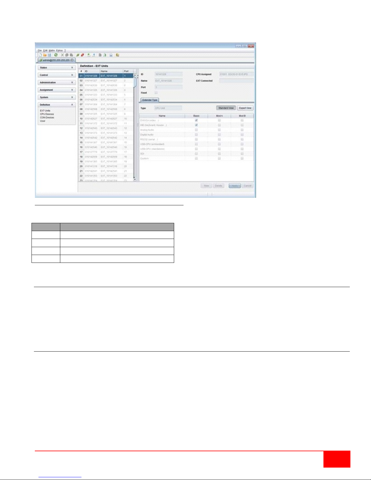
Button
Function
New
Create a new extender unit
Delete
Delete an existing unit
Apply
Confirm changes of an extender unit
Cancel
Reject changes
Managing Extender Settings through the Java Tool
Select Definition > EXT Units in the task area.
Figure 39. Managing Extender Settings through the Java Tool
Select between the following buttons:
Creating Flex-Port Extender Units
Extenders with ID function are automatically recognized by the system and cannot be created manually.
They were used at so called Flex-Ports at the matrix.
Note: The connection of fixed port extender unit (e. g. USB 2.0) to a Flex-Port can cause unintended
results.
Creating Fixed Port Extender Units
To create a new fixed-port extender unit (e.g. USB 2.0), proceed as follows:
1. Press the New button.
2. Select whether a template of a USB 2.0 CON unit (USB CON Unit) or USB 2.0 CPU unit (USB
CPU Unit) should be used.
3. Press the OK button.
4. Determine a port at the matrix that should be used with the USB 2.0 extender unit (Fixed Port).
The name of the USB 2.0 extender unit can also be changed (Name).
5. Press the Apply button to save the new extender unit.
Created extender units are always set as fixed port extender. These configurations are required to switch
USB 2.0 connections via the matrix.
Orion XC Installation and Operations Manual
45
Page 54

Field
Selection
Description
ID
Text
ID of the CPU unit
Name
Text
Name of the CPU device
Virtual Device
Activated
Create a new CPU device as a virtual CPU
Deactivated
Function not active
Allow Private
Activated
Allow switching to the respective CPU
device in Private Mode
Deactivated
Function not active (default)
Force Private
Activated
Force switching to the respective CPU only
in Private Mode
Deactivated
Function not active (default)
Fix Frame
Activated
Force showing a red frame when switching
to the respective CPU
Deactivated
Function not active (default)
Deleting Flex-Port Extender Units
It is not possible to delete Flex-Port extender units connected to the matrix.
Deleting Fixed Port Extender Units
To delete a fixed port extender unit (e. g. USB 2.0), proceed as follows:
1. Verify that the fixed port extender unit to be deleted is currently not assigned to a device.
2. Select the fixed port extender unit to be deleted in the selection list on the left side of the EXT
Units menu and confirm with the <Enter> key.
3. Press the Delete button.
4. Confirm the delete process with the Okay button.
Note: In order to make a fixed port available again for Flex-Port extender units after deleting a fixed port
extender unit, a restart of the matrix is necessary.
CPU Settings
New CPU devices are configured in this menu including their assignment to extenders. The assignment
helps to describe and switch more complex computer configurations (e.g. Quad-Head with USB 2.0) in the
matrix. This menu can be accessed in the OSD and the Java Tool.
Select between the following settings:
46
Orion XC Installation and Operations Manual
Page 55
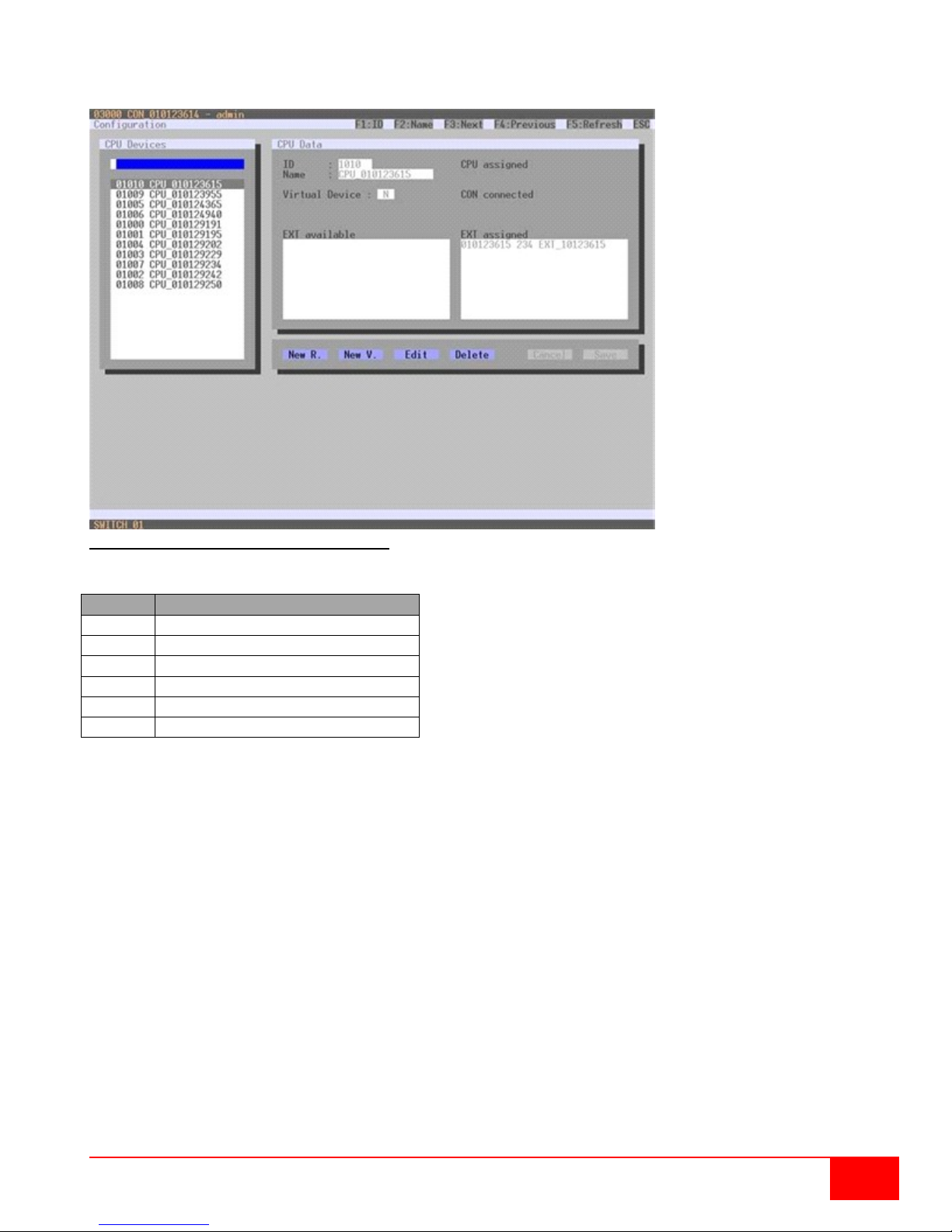
Button
Function
New R.
Create a new real CPU device
New V.
Create a new virtual CPU device
Edit
Edit an existing CPU device
Delete
Delete an existing CPU device
Cancel
Reject changes
Save
Save changes
Modifying CPU Settings through the OSD
Select Configuration > CPU Units in the main menu.
Figure 40. Modifying CPU Settings through OSD
Select between the following buttons:
Orion XC Installation and Operations Manual
47
Page 56
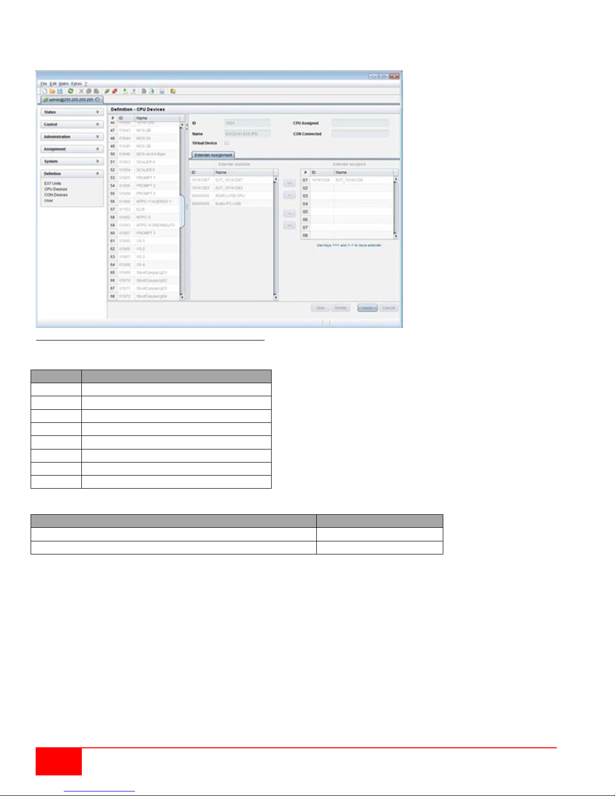
Button
Function
New
Open a new CPU Device
Delete
Delete a CPU Device
Apply
Confirm a created CPU Device
Cancel
Reject changes
>
Assign selected extender units
>>
Assign all available extender units
<
Remove the selected extender units
<<
Remove all extender units
Function
Keyboard Command
Change assignment number of the EXT unit upwards
<+>
Change assignment number of the EXT unit downwards
<->
Modifying CPU Settings through the Java Tool
Select Definition > CPU Devices in the task area.
Figure 41. Modifying CPU Settings through the Java Tool
Select between the following buttons:
Select between the following keyboard commands:
To create a new CPU device, proceed as follows:
1. Press the New button.
2. Select whether a real CPU (Create a real CPU) or a virt ual CPU (Create a virtual CPU) is to be
created, or if a template of an existing CPU should be used (Choose template).
Note: A template can only be used, if there is at least one existing CPU device.
3. Press the OK button.
4. Determine all parameters that are relevant for the CPU.
5. To confirm the new CPU, press t he Apply button.
48
Orion XC Installation and Operations Manual
Page 57

To access a new CPU via matrix, an assignment of one or more CPU type extender units is required.
Field
Selection
Description
ID
Text
ID of the CON Unit
Name
Text
Name of the CON Device
Virtual
Device
Activated
Create new CON device as a virtual one
Deactivated
Function not active (default)
Allow User
ACL
Activated
Allow activation of the User ACL at the local console
Deactivated
Function not active (default)
Force Login
Activated
Force user login at this CON device
Deactivated
Function not active (default)
LOS Frame
Activated
If there is a loss of connection, the last picture shown will be still
surrounded by an orange frame
Deactivated
Function not active (default)
Proceed as follows:
1. Select the CPU in the CPU Devices list that has to be assigned an extender.
2. Select one or more extenders in the Extender available list that should be assigned to the CPU.
3. Perform the assignment by pressing the > button. To assign all available extenders to the CPU,
press the >> button. The assignments are displayed in the Extender assigned list.
4. Confirm the assignment by pressing the Apply button.
To remove an extender assignment, proceed as follows:
1. Select a CPU in the CPU Devices list to be modified.
2. Select one or more extenders in the Extender assigned list to be removed.
3. Remove the assignment with the < button. To remove all existing assignments, press the << button.
4. Confirm the removal with the Apply button.
Console Settings
This menu provides the ability to modify console settings.
CON Devices
New CON devices are created in this menu. This includes setting up access rights and assignment to
extenders. This menu can be accessed in the OSD and the Java Tool.
Select between the following settings:
displayed and is surrounded by an orange frame
When switching to a CPU without video signal, a blank screen will appear
Orion XC Installation and Operations Manual
49
Page 58
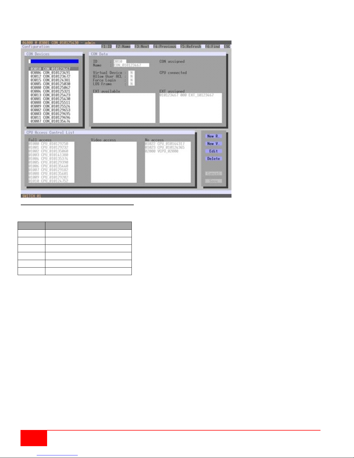
Button
Function
New R.
Create a new real console
New V.
Create a new virtual console
Edit
Edit an existing console
Delete
Delete an existing console
Cancel
Reject changes
Save
Save changes
Setting up CON Devices through the OSD
Select Configuration > CON Devices in the main menu.
Figure 42. Setting up CON Devices through OSD
Select between the following buttons:
50
Orion XC Installation and Operations Manual
Page 59
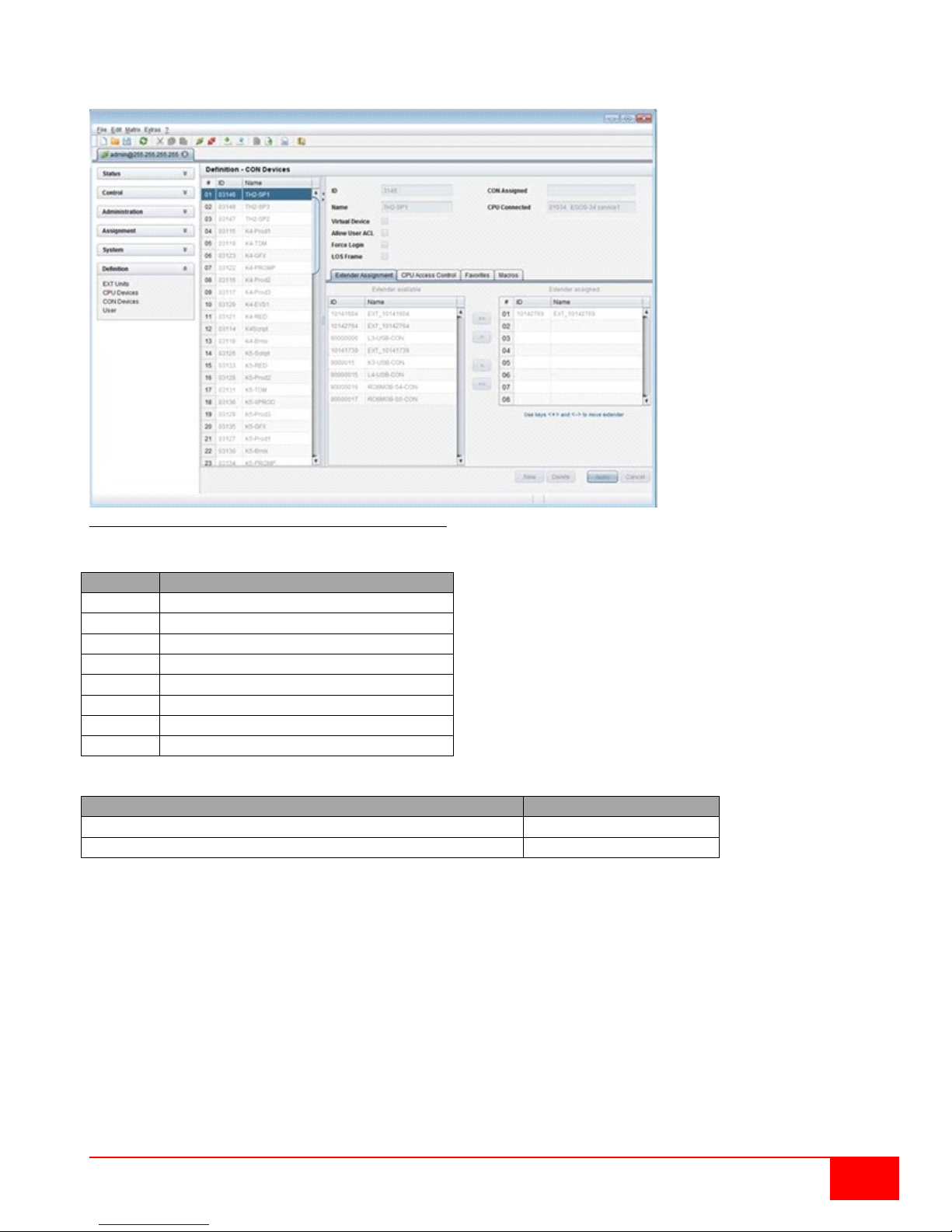
Button
Function
New
Open a new CON Device
Delete
Delete a CON Device
Apply
Confirm a created CON Device
Cancel
Reject changes
>
Assign selected extender units
>>
Assign all available extender units
<
Remove the selected extender units
<<
Remove all extender units
Function
Keyboard Command
Change assignment number of the EXT unit upwards
<+>
Change assignment number of the EXT unit downwards
<->
Setting up CON Devices through the Java Tool
Select Definition > CON Devices in the task area.
Figure 43. Setting up CON Devices through the Java Tool
Select between the following buttons:
Select between the following keyboard commands:
To create a new console, proceed as follows:
1. Press the New button.
2. Select if a real console (Create a real Console) or a virtual console (Create a virtual Console) is
to be created, or if a template of an existing console should be used (Choose template).
Note: A template can only be used, if there is at least one existing CON device.
3. Press the OK button.
4. Determine all parameters that are relevant for the console.
5. To confirm the new consol e, press the Apply button.
Orion XC Installation and Operations Manual
51
Page 60

Function
Keyboard Command
Add CPU to list Full Access
<F>
Add CPU to list Video Access
<V>
Add CPU to list No Access
<N>
Field
Selection
Description
Hor. Speed 1/x
1-9
Adjustment of the horizontal mouse speed,
1 = slow, 9 = fast (default value: 4)
Ver. Speed 1/x
1-9
Adjustment of the vertical mouse speed,
1 = slow, 9 = fast (default value: 5)
Double Click
100-800
Adjustment of the time slot for a double click
(default value: 200 ms)
Keyboard Layout
Region
Set the OSD keyboard layout according to the used
keyboard
Video Mode
Variable or specific resolution
Resolution that is used by the OSD
For a new CON to use the matr ix, an assignment of one or more CON type extender units is required.
Proceed as follows:
1. Select the console in the CON Devic e s list that has to be assigned an extender.
2. Select one or more extend ers in the Extender available list that should be assigned to the CON.
3. Perform the assignment by pressing the > button. To assign all available extenders to the console,
press the >> button. The assignments are displayed in the Extender assigned list.
4. Confirm the assignment by pressing the Apply button.
To remove an extender assignment, proceed as follows:
1. Select the console in the CON Devic e s list to be modified.
2. Select one or more extend ers in the Extender assigned list to be removed.
3. Remove the assignment with the < button. To remove all existing assign me nt s , pr es s the << button.
4. Confirm the removal with the Apply button.
To configure the access rights of consoles to CPUs, please proceed as follows:
1. Select a console in the CON Devices list.
2. Open the CPU Access Control tab.
3. Assign new access rights by using the right mouse button or the respective keyboard commands
(see the table below).
4. Confirm the configuration by pressing the Apply button.
Newly created users automatically have Full Access to all available CPUs.
Select between the following keyboard commands
Mouse and Keyboard
The configuration of the mouse and keyboard is done in this menu. This menu can be accessed in the
OSD and the Java Tool.
The following settings can be modified.
Note: The mouse and keyboard settings are console specific and can be separately set for every console.
52
Orion XC Installation and Operations Manual
Page 61
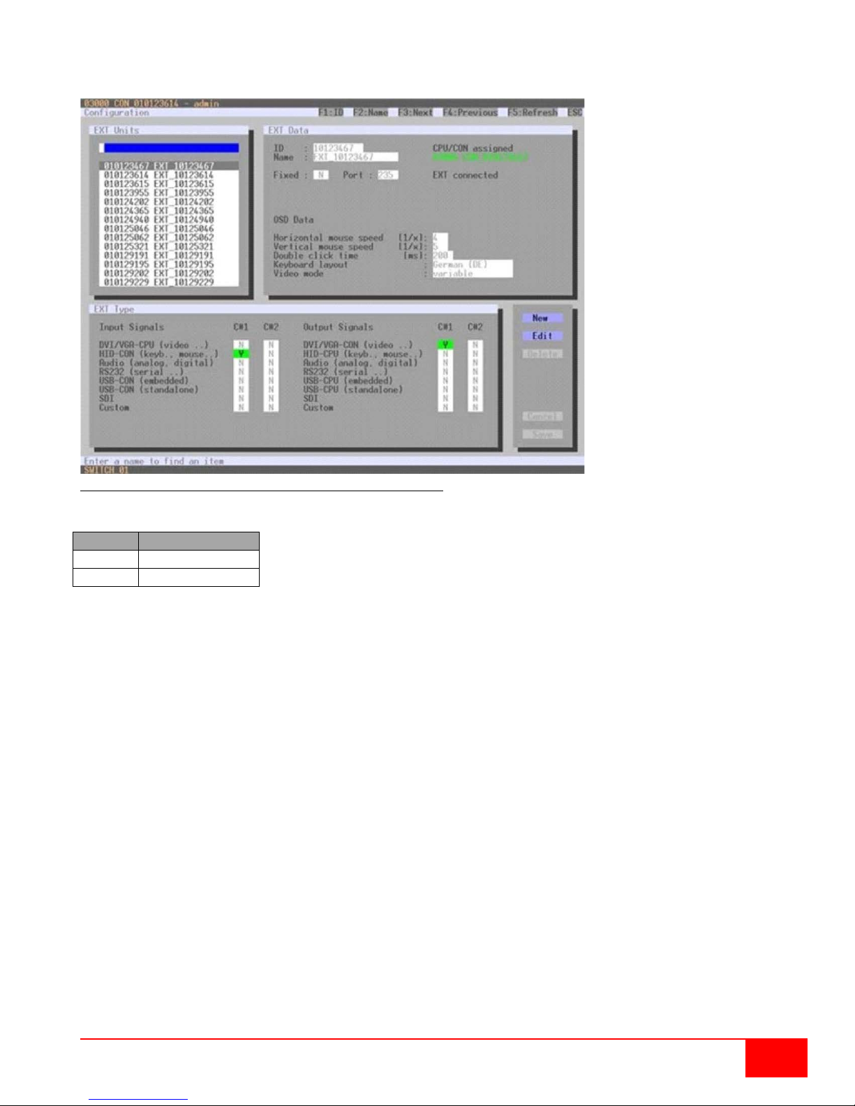
Modifying Mouse and Keyboard Settings through the OSD
Button
Function
Cancel
Reject changes
Save
Save changes
Select Configuration > EXT Units in the main menu.
Figure 44. Modifying Mouse and Keyboard Settings through OSD
Select between the following buttons:
Orion XC Installation and Operations Manual
53
Page 62
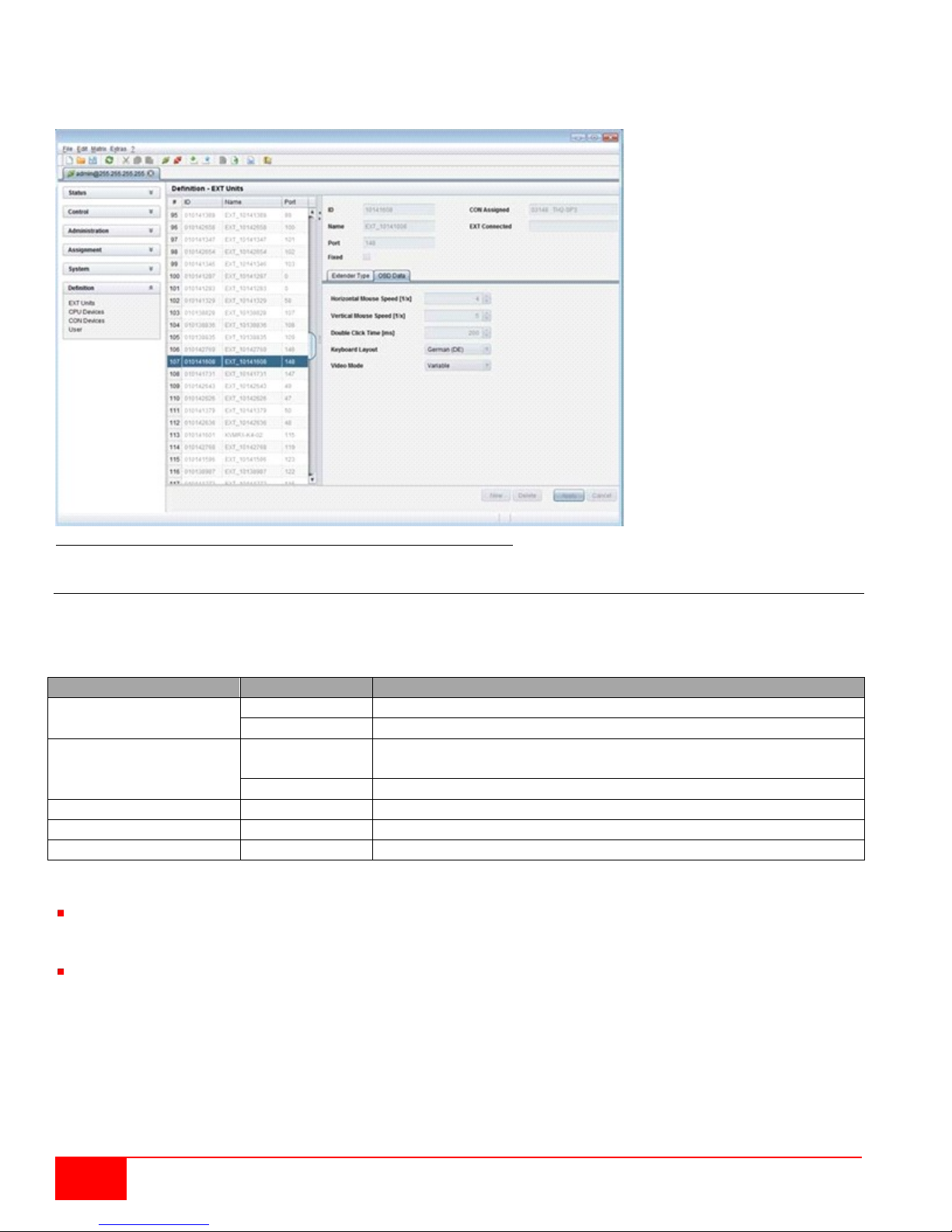
Modifying Mouse and Keyboard Settings through the Java Tool
Field
Selection
Description
Enable Extender OSD
Activated
Enable Extender OSD (default: YES)
Deactivated
Function not active
Update Connections
Activated
Update connection changes during fade-in of Extender OSD
(default: YES)
Deactivated
Function not active
Display Time
0-999 seconds
Duration of OSD fade-in (default: 10)
Horizontal Position
10 pixels
Horizontal OSD position (default: -2)
Vertical Position
10 pixels
Vertical OSD position (default: 2)
Select Definition > EXT Units in the task area.
Mouse and keyboard settings are made in the OSD Data tab.
Figure 45. Modifying Mouse and Keyboard Settings through the Java Tool
Extender OSD
The Extender OSD settings can be adjusted in this menu. These are local settings that can be set up
individually for each console.
Select between the following Extender OSD settings:
Notes:
When setting the horizontal OSD position, a prefixed minus describes the orientation to the right edge
of the monitor, e.g. -2 means 2 x 10 = 20 pixels of distance to this edge. When setting a vertical
position, a prefixed minus describes an orientation to the bottom edge of the monitor.
If the Update Connections function is deactivated, the Extender OSD only appears when switching via
OSD.
This menu can be accessed from the OSD and the Java Tool.
54
Orion XC Installation and Operations Manual
Page 63
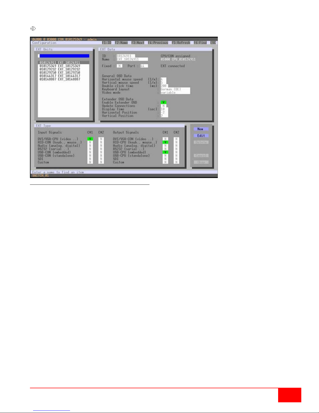
Modifying Extender OSD Settings through the OSD
Select Configuration > EXT Units in the main menu.
Figure 46.Modifying Extender OSD Settings through OSD
In order to change the Extender OSD settings, proceed as follows:
1. Select the console extender in the EXT-Units list whose Extender OSD settings has to be
adjusted.
2. Confirm the selection by pressing the <Enter> key, and the respective console extender will be
enabled for editing.
Orion XC Installation and Operations Manual
55
Page 64
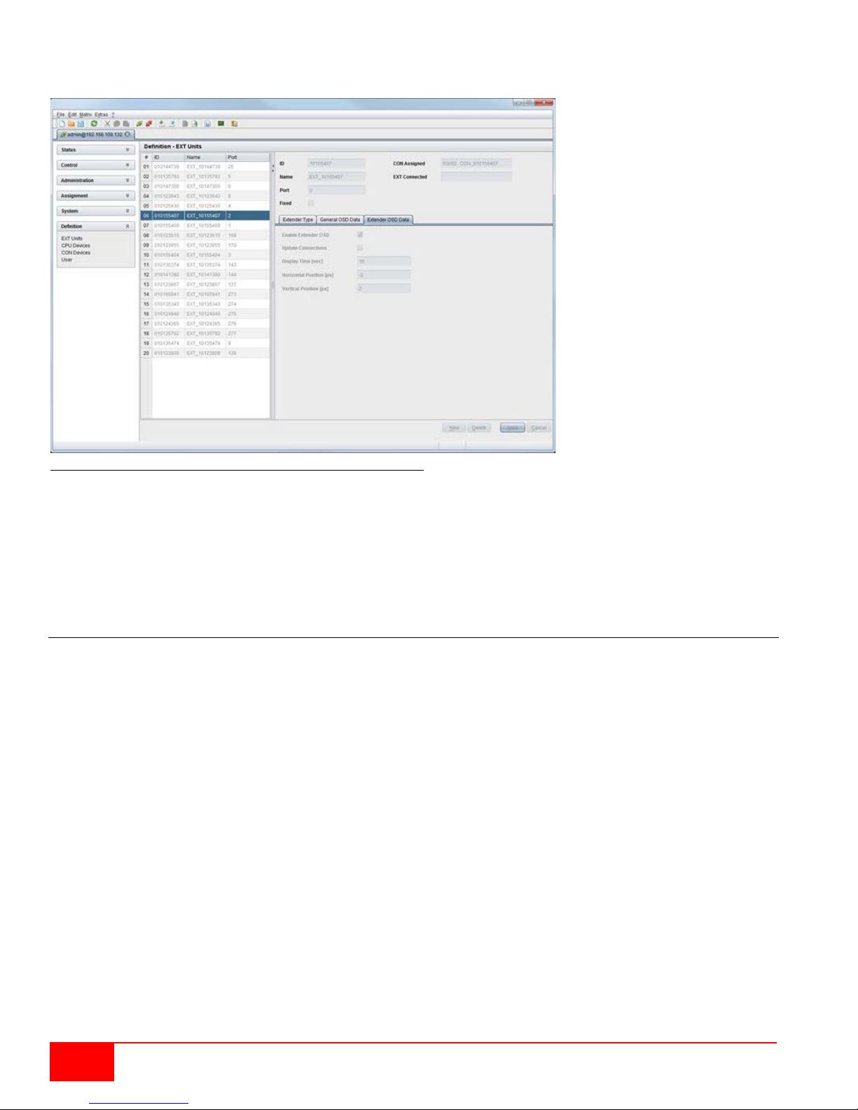
Modifying Extender OSD Settings through the Java Tool
Select Definition > EXT Units in the task area.
Figure 47. Modifying Extender OSD Settings through the Java Tool
In order to change the Extender OSD settings, proceed as follows:
1. Select the console extender in the EXT-Units list whose Extender OSD settings has to be
adjusted.
2. Open the Extender OSD Data tab.
3. Adjust the desired settings and confirm by pressing the Apply button.
Console Favorites
Individual lists of favorite CPUs that have to be switched frequently can be created for different consoles in
this menu. This menu can be accessed in the OSD and the Java Tool.
A favorites list can contain up to sixteen different CPUs. Switching between the favorites is done via 'Hot
Key' using the keyboard.
56
Orion XC Installation and Operations Manual
Page 65
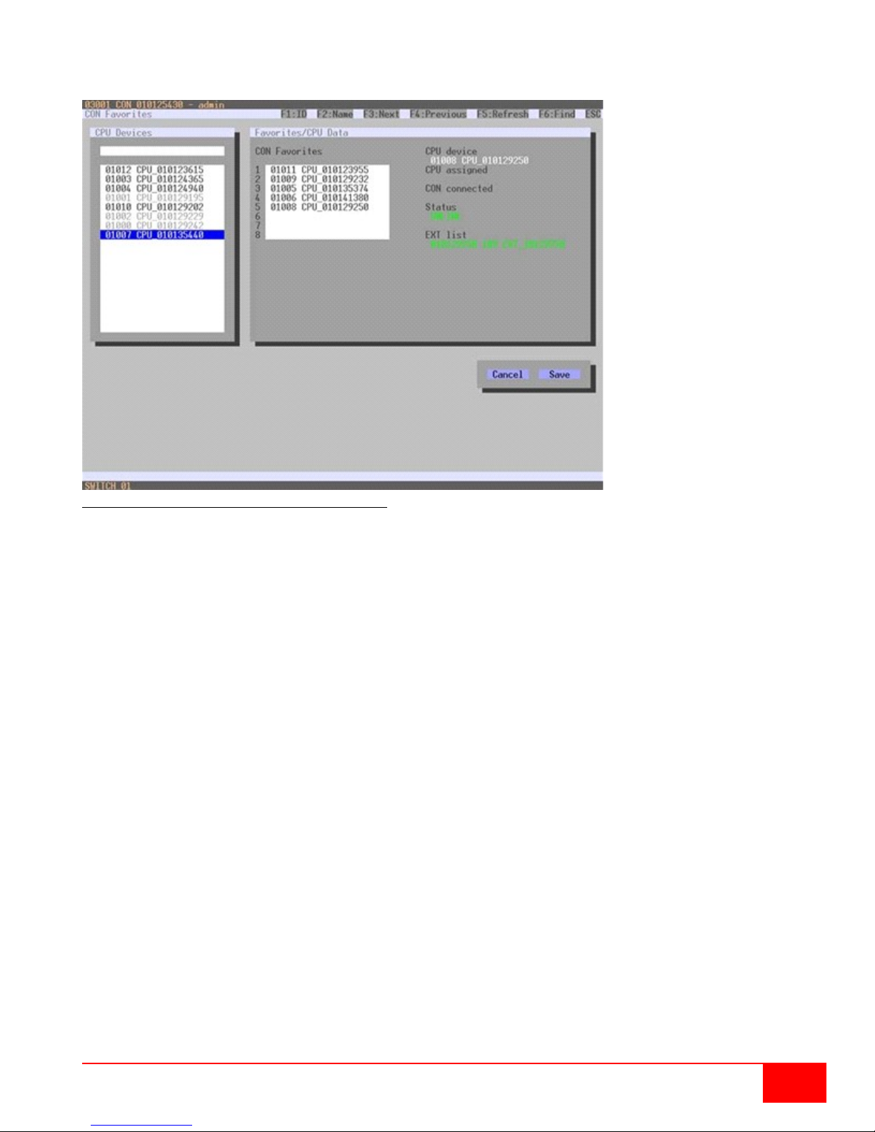
Setting up Console Favorites through the OSD
Select Assignments > CON Favorites in the main menu.
Figure 48. Setting up Console Favorites through OSD
To create a favorites list for the local console, proceed as follows:
1. Select successively those CPUs from the CPU Devi ce s list that have to be moved to the favorite
list. By pressing the <a> key, a CPU device will be moved to the favorite list and it will be removed
by pressing <r>.
2. The order of the CPU devices within the favorite list can be changed by pressing the <+> and <->
keys.
3. Press the Save button to save the settings.
Orion XC Installation and Operations Manual
57
Page 66
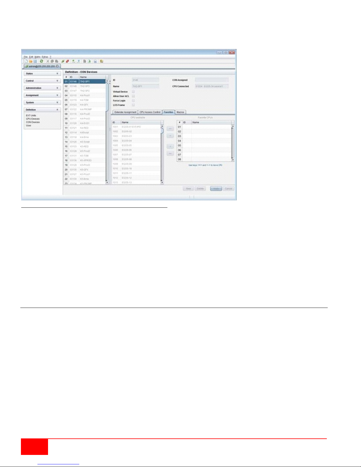
Setting up Console Favorites through the Java Tool
Select the respective user in the working area of the CON Devices menu for the favorite list and open
the Favorites tab.
Figure 49. Setting up Console Favorites through the Java Tool
To create a favorite list for any console, proceed as follows:
1. Select the CPUs in the CPU available list that should be added to the favorite list (CPU assigned).
Press and hold the <Ctrl> key to select more than one CPU device at a time.
2. Press the > button to move the marked CPU devices to the favorite list. If the >> button is pressed,
the first eight CPU devices from the CPU available list will be moved to the favorite list (CPU
assigned).
3. The position of a selecte d C PU device within the f av orites list can be changed by pressing the <+>
and <-> keys.
4. To remove marked CPU devices from the favorite list, press the < button. If the << button is
pressed, all CPU devices will be removed from the favorite list.
Console Macros
This menu is used to set up macro commands for switching, disconnection or user administration. This
menu can be accessed in the OSD and the Java Tool.
The macro commands are created for each console separately. A single macro can execute up to 16
switching commands successively. The execution of the macros is done via 'Hot Key' and the function
keys <F1>-<F16>.
58
Orion XC Installation and Operations Manual
Page 67
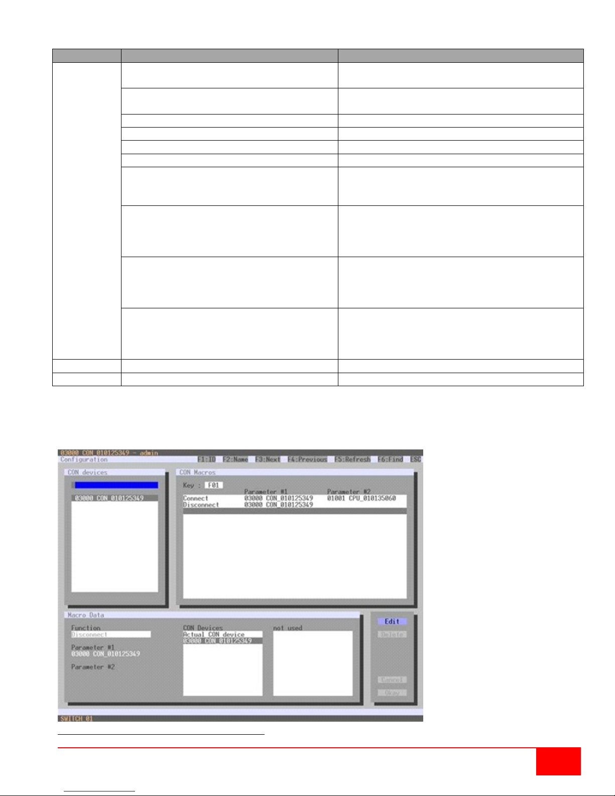
Field
Selection
Description
Function
Connect (P1=CON, P2=CPU)
Set bidirectional connection from console P1 to
CPU P2
Connect Video (P1=CON, P2= CPU)
Set video connection from console P1 to CPU
P2
Disconnect (P1=CON)
Disconnect console P1
Logout User
Logout current user
Set Real CPU (P1=VCPU, P2=RCPU)
Assign a virtual CPU to a real CPU
Set Virtual CON (P1=RCON, P2=VCO N)
Assign a real console to a virtual console
Push (P1=CON)
The console’s KVM connection is forwarded to
connection.
Push Video (P1=CON)
The video signal of the console’s current
unchanged (KVM or video only).
Get (P1=CON)
The console gets a KVM connection to the CPU
video only connection.
Get Video (P1=CON)
The console gets a video only connection to the
unchanged (KVM or video only).
P1
CON or CPU Device
Name of CON or CPU device
P2
CON or CPU Device
Name of CON or CPU device
Select between the following settings:
(01-16)
console P1 and is changed to a video only
connection (KVM or video only) is forwarded to
console P1. The console’s connection remains
that is currently connected to console P1. The
connection of console P1 is changed into a
CPU that is currently connected to console P1.
The connection of console P1 remains
Setting up Console Macros through the OSD
Select via Configuration > CON Macros in the main menu that console for which a console macro has
to be created.
Figure 50. Setting up Console Macros through OSD
Orion XC Installation and Operations Manual
59
Page 68
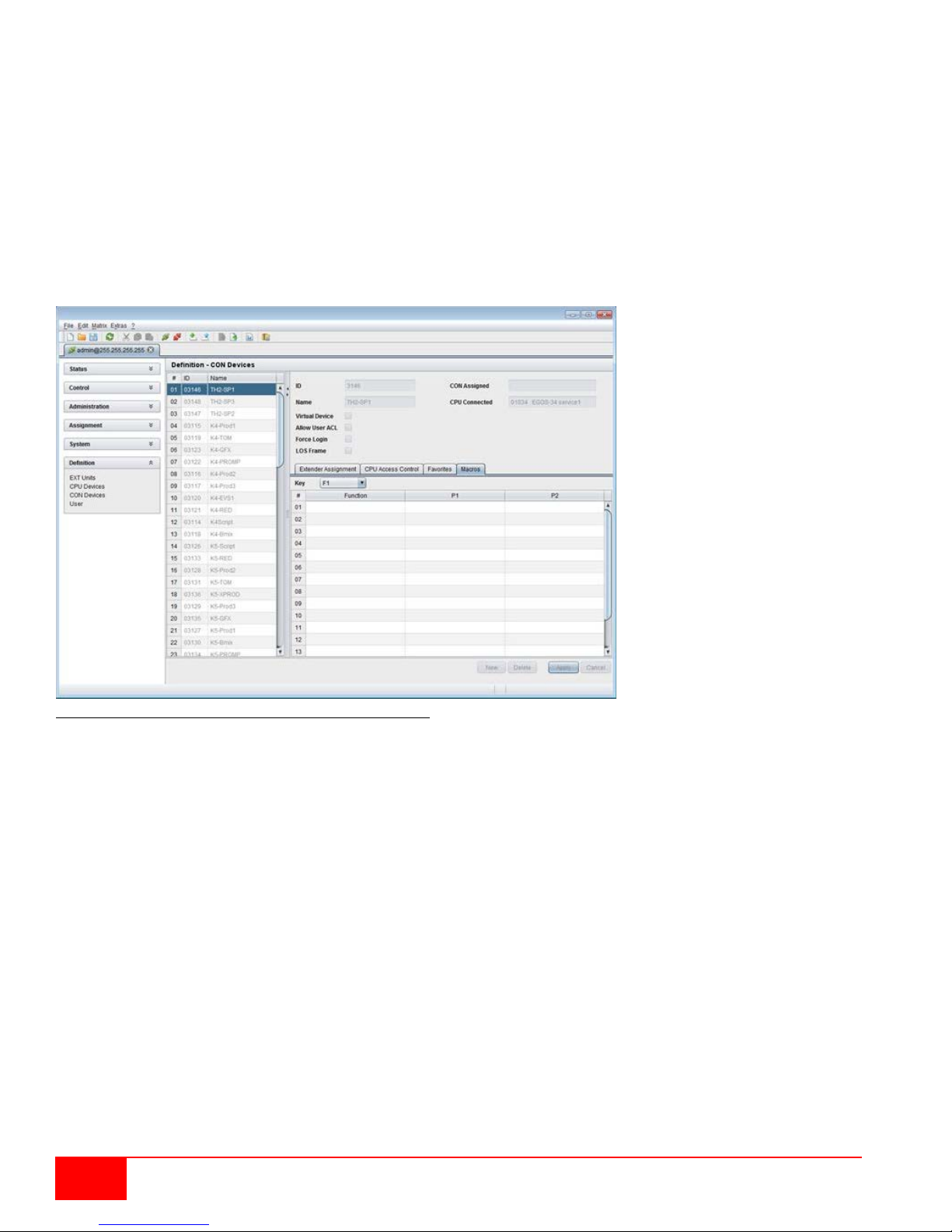
To create a macro for the selected console, proceed as follows:
1. Select in the Key field the number (1-16) of the macro you wish to create.
2. Select the respective place on the list (1-16) of the key that has to be set with a macro key.
3. Select for the marked place on the list a macro command in the Macro Data field.
4. Set the necessary parameters P1 and P2 (e.g. CON Devices or CPU Devices) for the selected
macro command.
5. Confirm the inputs by pressing the <Enter> key and repeat the process for further macro
commands, if necessary.
Setting up Console Macros through the Java Tool
Select in the working area of menu Definition > CON Devices that console for which a console macro
has to be created and open the Macros tab.
Figure 51. Setting up Console Macros through the Java Tool
To create a macro for the selected console, proceed as follows:
1. Select in the Key field the F key (F1 to F16) to which a macro is to be assigned.
2. Select in the Function column the commands that should be part of the macro. The selection list is
opened by a double click on the empty fields.
3. Select in the P1 and P2 columns the respective parameters for the macro functions (e.g.
corresponding consoles and CPUs).
4. Confirm the inputs by pressing the Apply button.
For an efficient macro configuration the following context functions are available:
By right clicking on the Macros tab, macros can be assigned to other consoles using the Assign
Macros to ... function, and can be copied from other consoles by using the Copy Macros from ...
function.
By right clicking on the macro list, macros of the selected key can be copied into the cache by using
the Copy Key Macros function. The macros can be pasted from the cache into a key by using the
Paste Key Macros function, and all macros of the selected key can be reset by using the Reset
Key Macros function.
60
Orion XC Installation and Operations Manual
Page 69
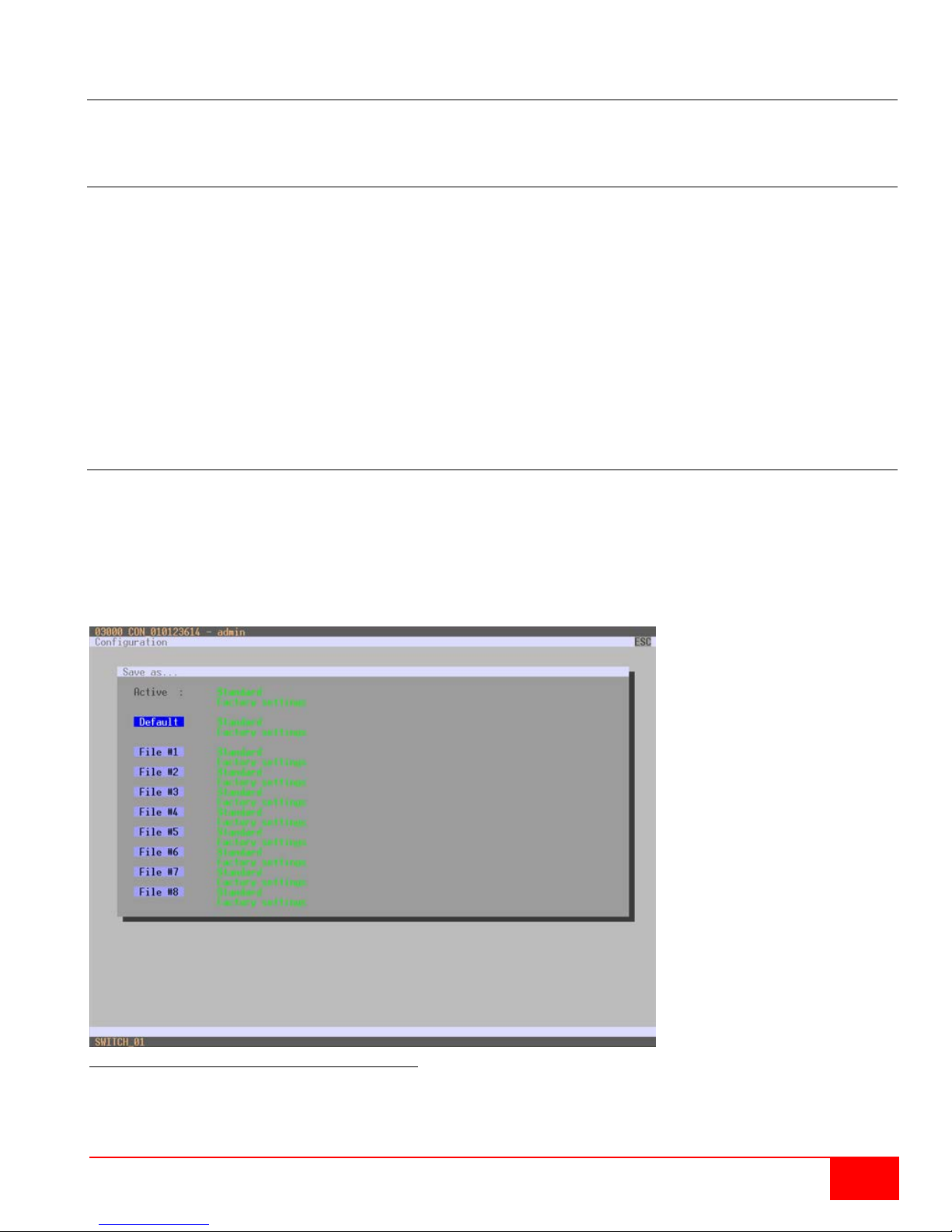
Saving and Loading of Configurations
This menu facilitates saving and loading of active configurations, internal configurations and external
configurations, as described below.
Active Configuration
This menu can only be accessed in the OSD.
Select Configuration > Save in the main menu.
By selecting this menu item, the active configuration of the matrix is saved to non-volatile matrix
memory. By default, the last configuration that has been saved in this way will be restored after a
restart of the ma trix.
Changing configurations or saving them blocks the matrix memory and leads to a freeze of all OSD menus
for a few seconds. The connections between consoles and CPUs are not affected by this freeze.
If Auto Save within the system settings is selected, an additional automatic sa ving of the config uration will
be performed periodicall y .
Saving of Configurations (internal)
This menu allows saving the current configuration to predefined internal storage locations. The menu can
be accessed from the OSD and the Java Tool.
Saving the Configuration to Internal Storage through the OSD
It is possible to save the created configuration to eight storage locations in the matrix (File #1 - File # 8).
Additionally a configuration can also be saved as default configuration.
Figure 52. Saving internal configuration through OSD
Active shows the current configuration’s name and description. This configuration can be saved now.
Orion XC Installation and Operations Manual
61
Page 70
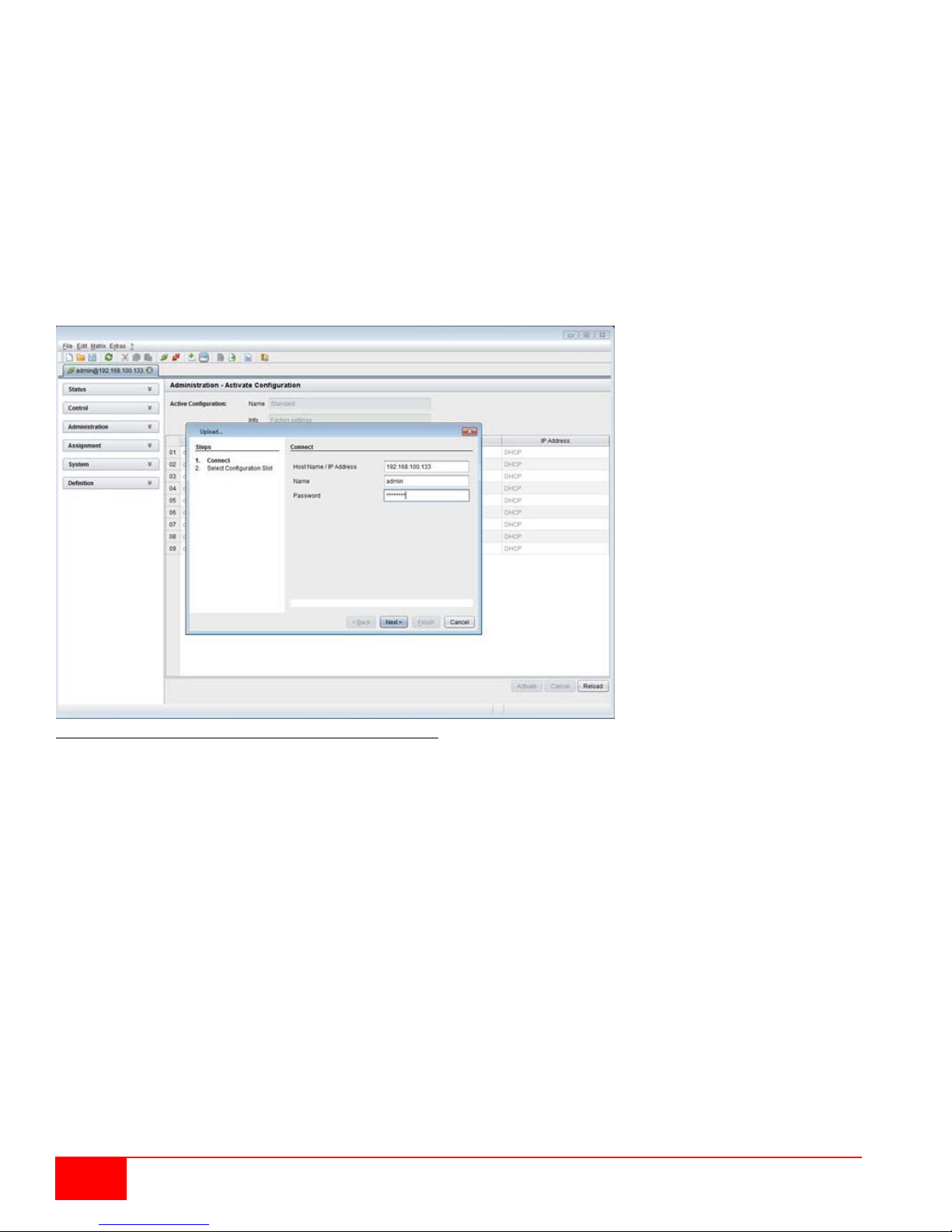
In Default and File #1 to File #8, the name and the detailed information of the respective saved
configuration are shown. Each of these storage locations can be overwritten.
The storage location to be overwritten by the current configuration must be selected explicitly.
The current configuration is then saved to this storage location and will be immediately shown in the menu.
The previously saved configuration at that storage location is deleted.
To save the configuration into an internal matrix memory location, proceed as follows:
1. Select Configuration > Save As… in the main menu.
2. Select the desired storage location (File #1 – File #8, or Default).
Saving Internal Configuration through the Java Tool
Figure 53. Saving internal configuration through the Java Tool
To save the configuration into the internal matrix memory, proceed as follows:
1. Select File > Upload in the menu bar.
2. Enter the IP address of the matrix, your user name and password and confirm the inputs with the
Next button.
3. Select the storage location in which the configuration has to be saved (default or config01 config08) and confirm with the OK button.
62
Orion XC Installation and Operations Manual
Page 71
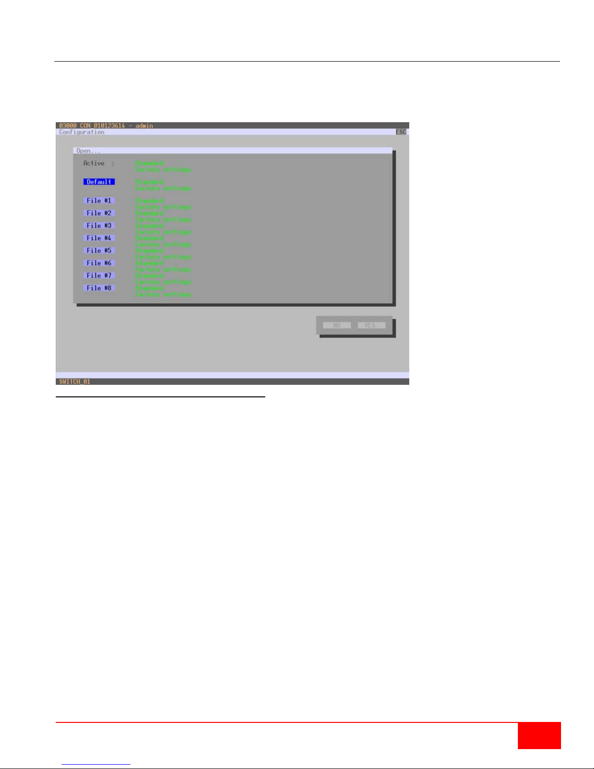
Loading of Configurations (internal)
Previously saved configurations are loaded in this menu. This menu can be accessed from the OSD and
the Java Tool.
Loading Internal Configuration through the OSD
Figure 54. Loading internal configuration through OSD
Active shows the current configuration’s name and description. In addition to the default configuration, up
to eight further configurations can be loaded.
Select the configuration to be loaded from one of the nine locations. The selected configur ation is
immediately loaded and displayed in the menu as Active. The previously active configuration is deleted.
To load the configuration from the internal matrix memory, proceed as follows:
1. Select Configuration > Open in the main menu.
2. Select the desired configuration.
3. Load the configuration by pressing the <Enter> key.
Orion XC Installation and Operations Manual
63
Page 72
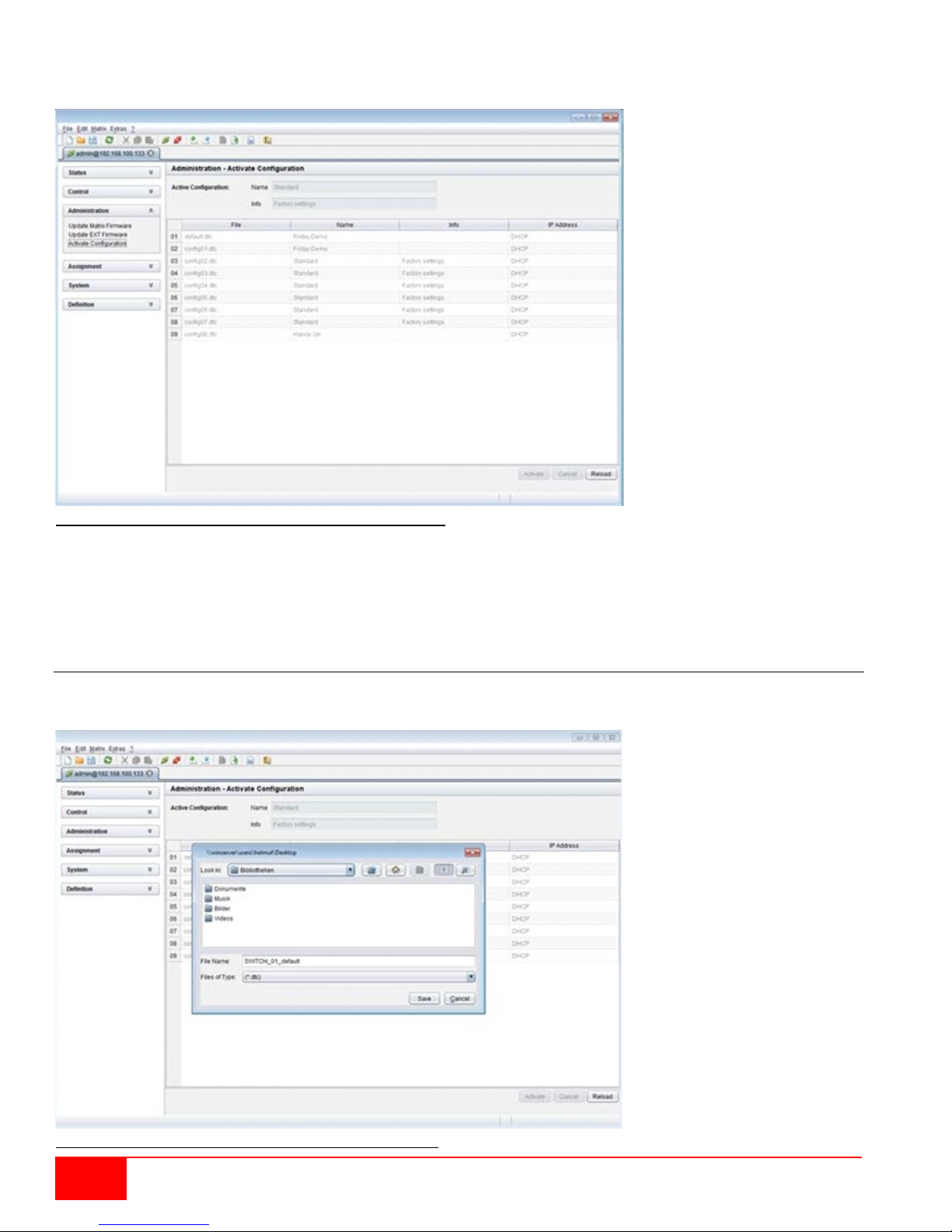
Loading Internal Configuration through the Java Tool
Figure 55. Loading internal configuration through the Java Tool
To load the configuration from the internal matrix memory, proceed as follows:
1. Select Administration > Activate Configuration during online-mode in the task area.
2. Select the required configuration.
3. Load the configuration by pressing the Activate button.
Saving of Configurations (external)
Created configurations can be saved as a file and so become transportable and independent of the
individual matrix. This menu can only be accessed in the Java Tool.
Figure 56.Saving external configuration through the Java Tool
64
Orion XC Installation and Operations Manual
Page 73
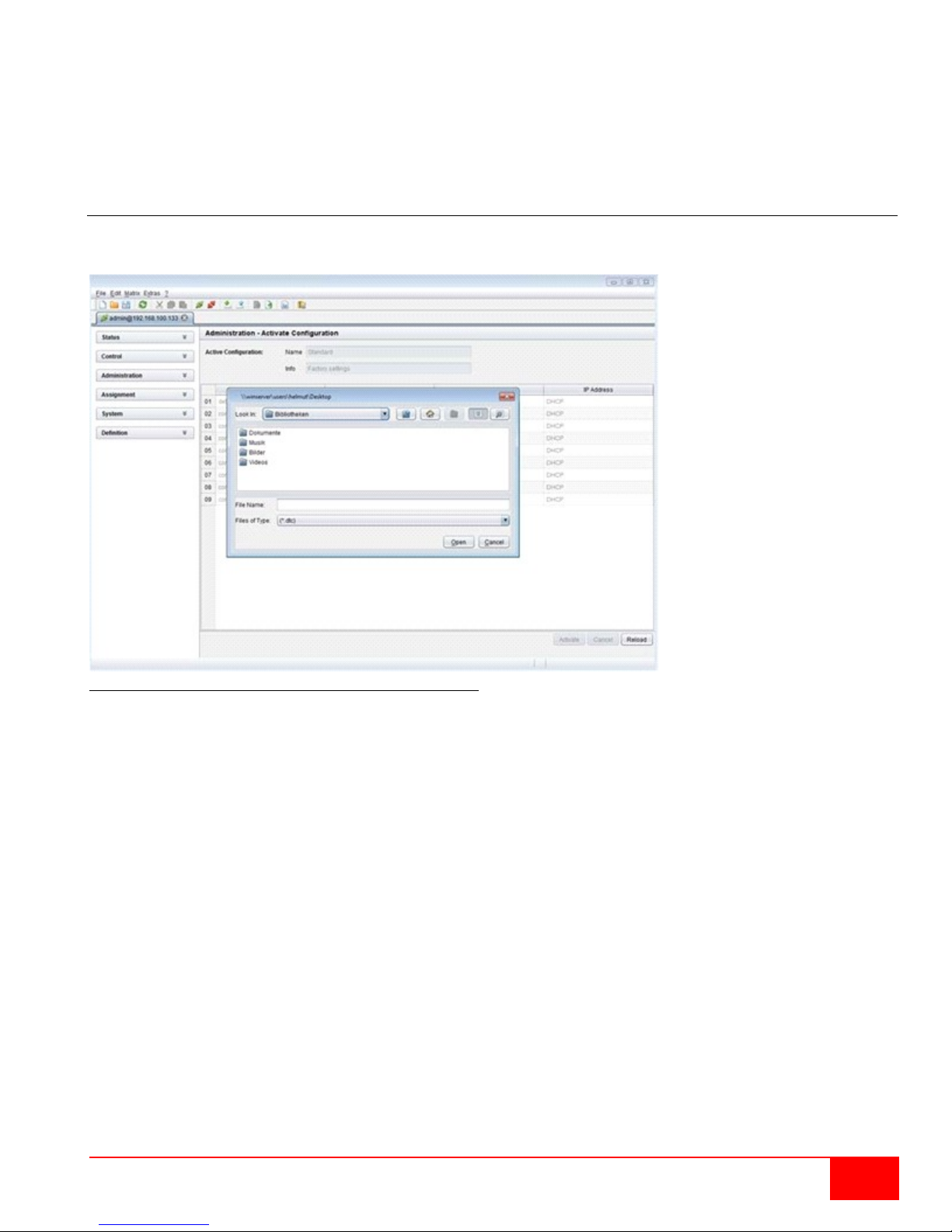
To save the configuration into to an external configuration file, proceed as follows:
1. Select File > Save As in the menu bar.
2. Enter a name for the configuration.
3. Select the directory of the configuration on the storage medium where it has to be saved.
Configurations are always saved in a file with the ending “dtc”.
Loading of Configurations (external)
Externally saved configurations are opened, uploaded, and activated in this menu. This menu can only be
accessed in the Java Tool.
Figure 57.Loading external configuration through the Java Tool
To load an external configuration file, proceed as follows:
1. Select File > Open… during offline-mode and select the storage location of the configuration file
that has to be opened.
2. Open the configuration by pressing the Open button.
3. Select File > Upload in the menu bar to transfer the opened configuration to the matrix. Enter the
necessary parameters.
4. Select Matrix > Connect in the menu bar to make a connection between the matrix and the Java
tool. Enter the necessary parameters.
5. Select Administration > Activate Configuration and select the configuration that has to be
activated.
6. Confirm the process with the Activate button.
The opened configuration is activated now and can be used.
Orion XC Installation and Operations Manual
65
Page 74
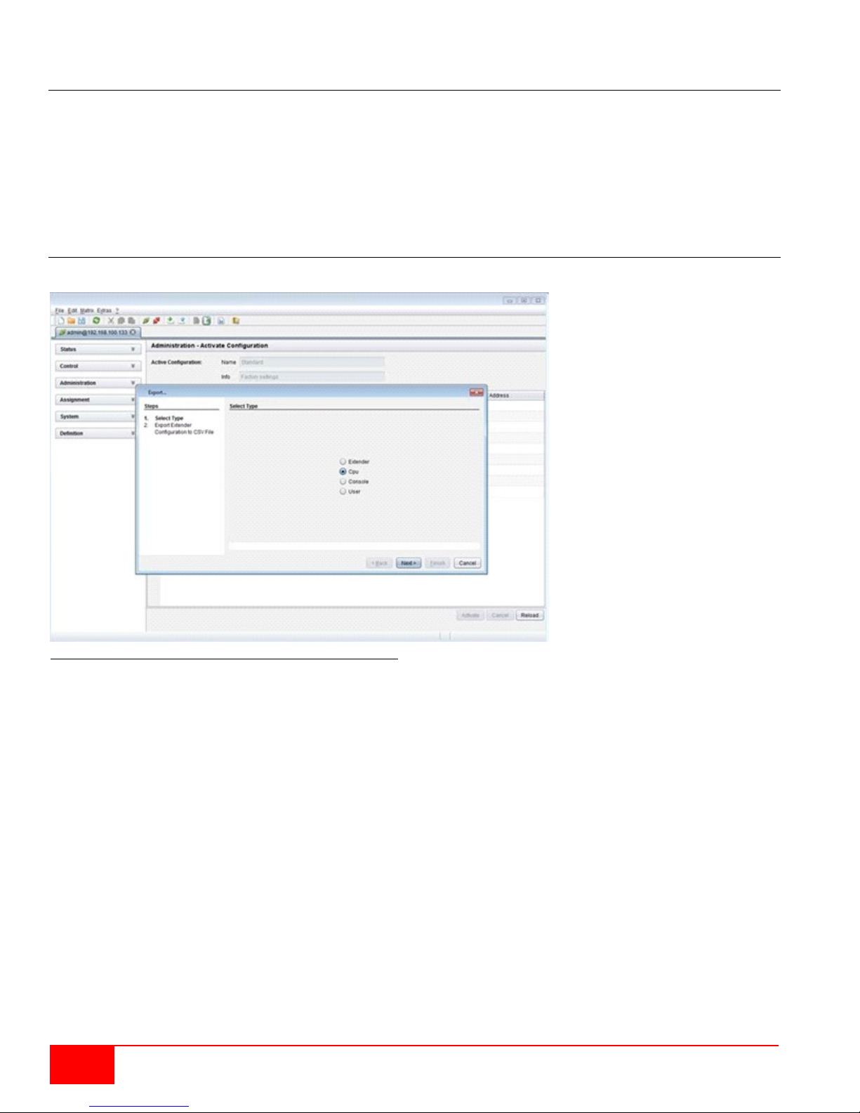
Export and Import Options
The Orion XC offers the possibility to read out available configuration lists (extender, CPUs, consoles and
users) for exporting and importing via the Java tool.
Exported configuration lists are always saved in .csv format that allows offline editing with common
spreadsheet applications.
Import and Export are only available through the Java Tool.
Export Options
Configuration lists are exported in this menu.
Figure 58. Exporting Configuration Lists through the Java Tool
To export, proceed as follows:
1. Select File > Export in the menu bar.
2. After opening the menu, select the list to export (Extender, CPU, Console or User).
3. Select the storage location for the export file.
4. Confirm the export with the Finish button.
66
Orion XC Installation and Operations Manual
Page 75
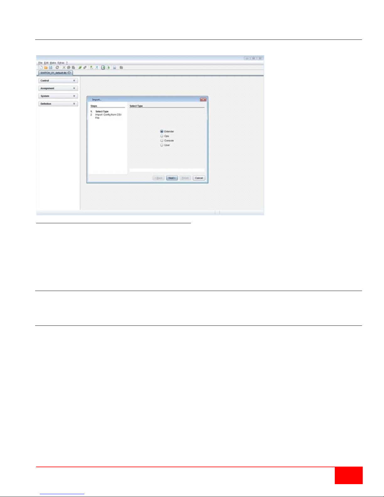
Import Options
Configuration lists are imported in this menu.
Figure 59. Importing Configuration Lists through the Java Tool
To import, proceed as follows:
1. Select File > Import in the menu bar.
2. After opening the menu, select the list to import (Extender, CPU, Console or User).
3. Select the directory of the list to import.
4. Confirm the import with the Finish button.
Firmware Update
This includes updating the firmware on the Orion XC matrix and the extenders. Firmware update is only
available through the Java Tool.
Matrix Update
The firmware of the matrix can be updated in this menu.
Notes:
Only use computers to update the matrix that are self-sustaining and not integrated in the KVM
extender / matrix setup.
Ensure that the computer used for the update does not go into standby mode or sleep mode during
the update.
Ensure that the configuration has been saved externally before the update is started.
Preparation
Take the following steps in order prepare for the matrix update:
1. Save the matrix configuration externally.
2. Open Extras > Options in the menu bar and enter in the Firmware Directory setting the directory
from which the update files should be sourced by default.
Orion XC Installation and Operations Manual
67
Page 76
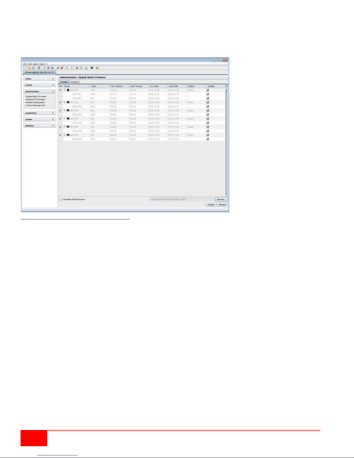
Ensure implicitly that all USB 2.0 extenders are only connected to the provided ports (fixed ports) before the
matrix update is started. Failure to observe this requirement will have a negative influence on the stability
of the update.
Performing the Update
Figure 60. Matrix Update through the Java Tool
To perform the matrix update, proceed as follows:
1. Select Administration > Update Matrix Firmware in the task area. All updateable components of
the matrix will be automatically selected and highlighted in green
2. Start the update by pressing the Update button in the pop up window that appears.
3. Restart the Matrix after the update by pressing the Restart matrix button in the lower part of the
working area.
For a complete initialization of the matrix, a cold start (power cycle) is recommended.
68
Orion XC Installation and Operations Manual
Page 77
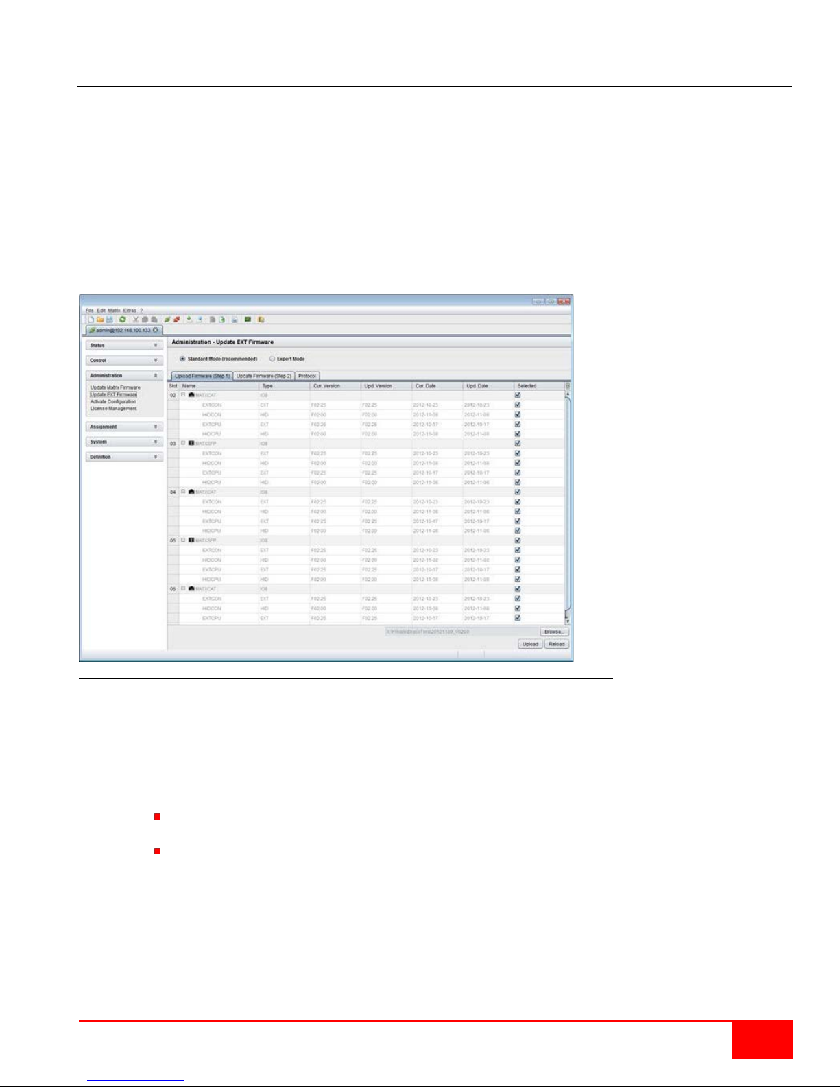
Extender Update
The firmware of the extenders connected to the matrix can be updated in this menu.
Preparation
Take the following steps in order prepare for the extender update:
1. Save the matrix configuration externally.
2. Open Extras > Options in the menu bar and enter in the Firmware Directory setting the directory
in which the update files should be found by default.
Performing the Update in Standard Mode (Parallel Update)
1. Select Administration > Update EXT Firmware in the task area. The standard mode for the
parallel update will be selected by default, and the Upload Firmware tab will be opened.
Figure 61. Extender Update in Standard Mode through the Java Tool - Step 1 (Upload Firmware)
2. Before the actual update process, all firmware files have to be uploaded to the respective I/O
boards on that extenders have to be updated. By selecting the update files, the I/O boards will be
automatically chosen for the upload in the Selected column and highlighted in green, but only if a
newer firmware version is selected.
3. Start the upload and distribution of the update files by pressing the Upload button.
Notes:
While performing the upload process, no update files will be installed. The update process
can be performed at a later time.
If all I/O cards are not selected, the upload of the update files will be performed in sequence.
Orion XC Installation and Operations Manual
69
Page 78
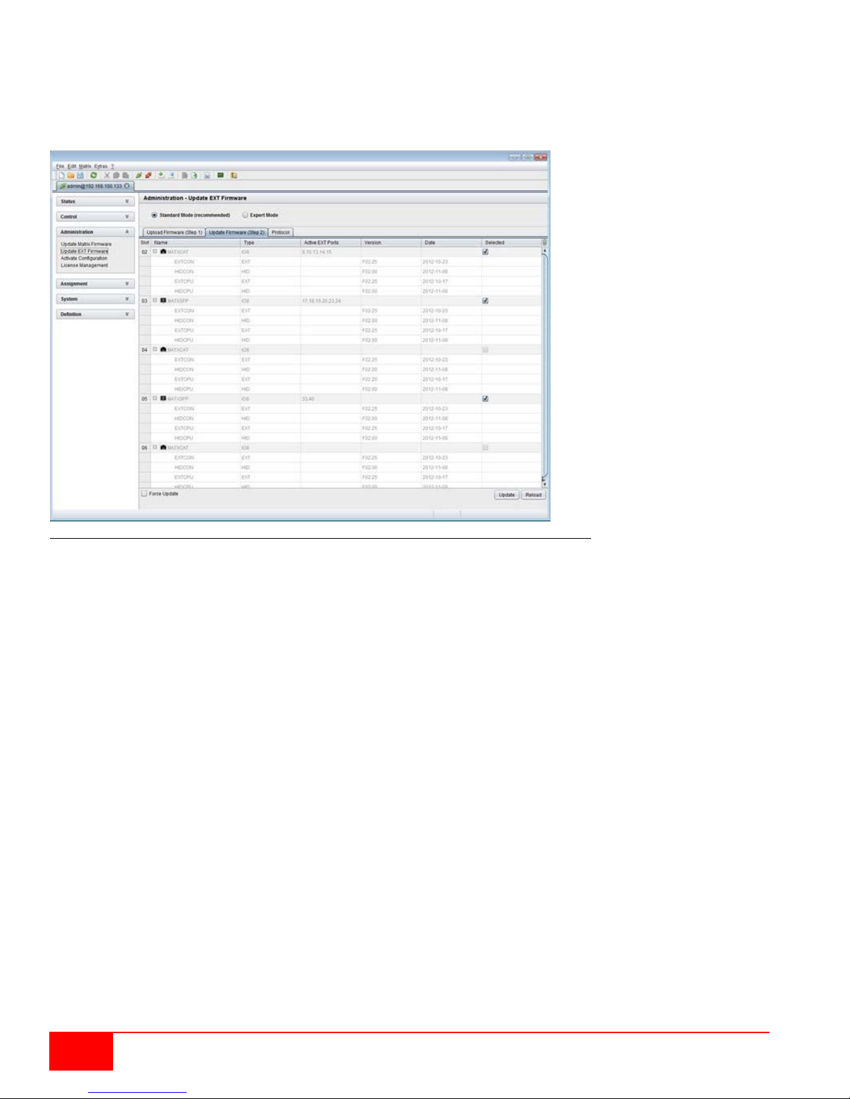
4. After finishing the upload process the successful completion will be confirmed by a popup. To start
the actual update process, confirm this by pressing the Yes button. The Java Tool will immediately
proceed to the Update Firmware tab.
Note: When updating with a firmware identical to or older than the version currently installed, the
Force Update option in the lower part of the working area has to be enabled.
Figure 62. Extender Update in Standard Mode through the Java Tool - Step 2 (Update Firmware)
5. Start the actual update process by pressing the Update button.
Note: Just before the update process, all affected I/O boards will be set into Service Mode and
retrieved gradually after finishing the respective updates.
70
Orion XC Installation and Operations Manual
Page 79
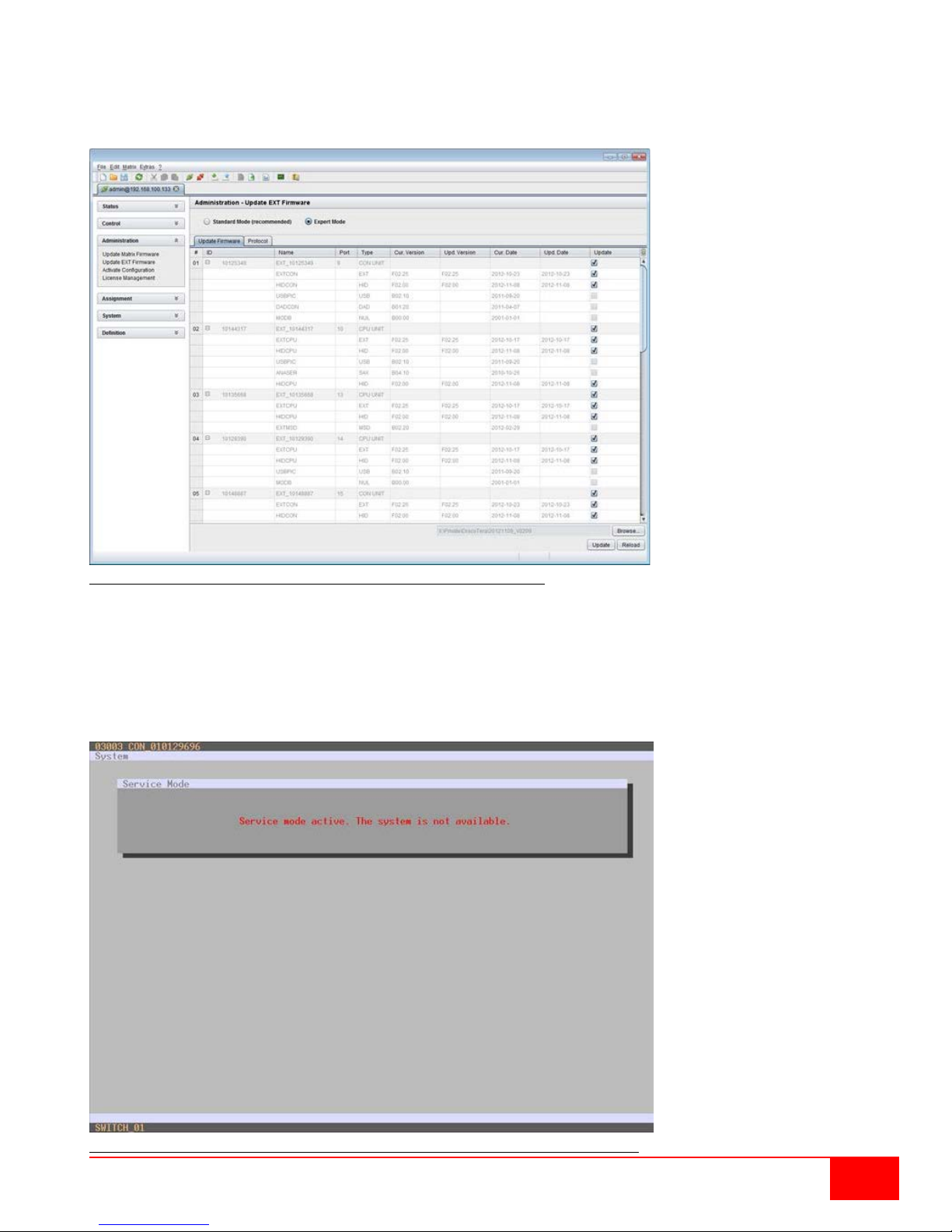
Performing the Update in Expert Mode (sequential Update)
1. Select Administration > Update EXT Firmware and select Expert Mode in the upper part of the
working area. All extenders available for update will be automatically selected and highlighted in
green.
Figure 63. Extender Update in Expert Mode – Step 1 (from the Java Tool)
2. Set the matrix into Service Mode upon request in the popup window or via Matrix > Activate
Service Mode in the menu bar.
Note: During Service Mode, all matrix functions are disabled on the I/O boards on which an update
is currently being performed. An OSD popup appears on all monitors connected to the matrix via a
CON device indicating Service Mode is active. Additionally, the Service Mode is indicated by a red
tool icon in the lower part of the working area.
Figure 64.Extender Update in Expert Mode – Step 1 (from the Service Mode of the OSD)
Orion XC Installation and Operations Manual
71
Page 80
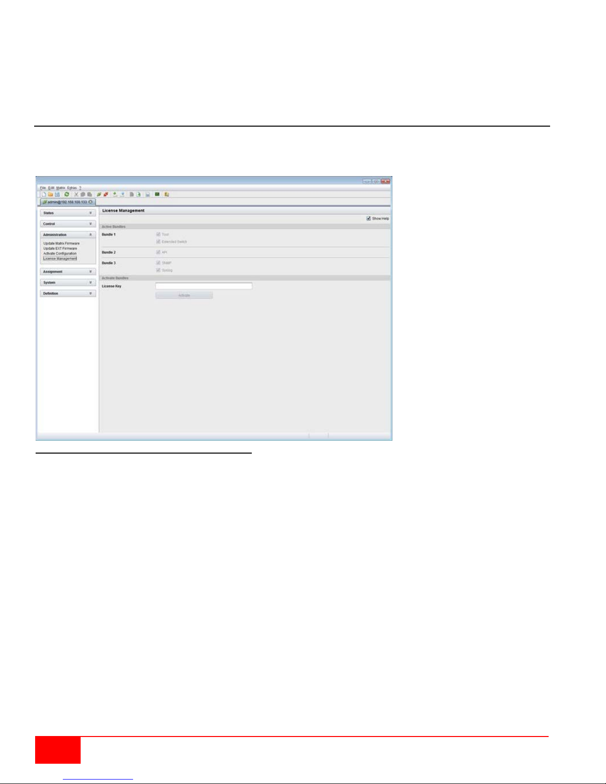
3. Start the update by pressing the Update button in the lower part of the working area.
4. Quit Service Mode after updating upon request in the popup window or via Matrix > Deactivate
Service Mode in the task area.
5. After the update, verify in the Java tool through Administration > Update EXT Firmware from the
Protocol tab of the Expert Mode that the updates for all extenders have been installed correctly.
License Management
The matrix can be upgraded with new function bundles by using license keys from this menu. Contact your
distributor to purchase license keys to upgrade matrix functions. This menu is accessible only from the
Java Tool.
Figure 65. License Management through the Java Tool
In order to activate a function bundle, proceed as follows:
1. Select Administration > License Management in the task area.
2. Enter the license key in the working area under Activate Bundles in the License Key field.
3. In order to activate the license key press the Activate button. The new functions will be
immediately enabled, and a restart of the matrix is not necessary.
72
Orion XC Installation and Operations Manual
Page 81

OPERATION
Operation
The Orion XC can be operated in three different ways:
1. Direct Switching
by commands from a keyboard connected to a CON port and the 'Hot Keys'
by commands from a macro keyboard connected to a console port
2. OSD
via the OSD using a keyboard/mouse connected to a CON Unit
3. External Switching Commands
From an external computer running the Java tool (network connection required)
via a media controller (network or serial connection required)
Operation via 'Hot Keys'
Several operations on the Orion XC can be performed using just the ‘Hot Keys’ on the keyboard, as
described below.
Direct Switching
Direct switching by 'Hot Keys' on a keyboard is the quickest way to switch your console between different
CPUs. You can switch video, keyboard and mouse together, or only video.
Direct Switching of Video, Keyboard and Mouse
1. Start Command Mode with the 'Hot Key'.
The keyboard LEDs Caps Lock and Scroll Lock will flash while Command Mode is active.
2. Enter the index number of the new CPU from the list of favorites and confirm with <Enter>.
Command Mode is closed and the console is connected to the new CPU with complete control.
Example: Switch video, keyboard and mouse to number 7 in the favorite CPU list (default hot key)
<left Shift>, <left Shift>, <7>, <Enter>
Note: The fastest switching will be achieved by using identical mice, keyboards and monitors. This
contributes to a smooth and seamless direct switching of the matrix.
Switching in Private Mode
1. Start Command Mode with the 'Hot Key'.
The keyboard LEDs Caps Lock and Scroll Lock will flash while Command Mode is active.
2. Enter the index number of the new CPU from the list of favorites and confirm with <left Shift>,
<Enter>.
Command Mode is closed and the console is connected to the new CPU with complete control in
Private Mode.
Example: Switching to number 3 in the favorite CPU list in Private Mode
<left Shift>, <left Shift>, <3>, <left Shift>, <Enter>
Direct Switching of Video
1. Start Command Mode with the 'Hot Key'.
The keyboard LEDs Caps Lock and Scroll Lock will flash while Command Mode is active.
2. Enter the index number of the new CPU from the list of favorites and confirm with <Space>.
Command Mode is closed and the console is connected to the new CPU with video only.
Example: Switching to number 1 in the favorite CPU list with video only
<left Shift>, <left Shift>, <1>, <Space>
Orion XC Installation and Operations Manual
73
Page 82

Switch to previous CPU
1. Start Command Mode with the 'Hot Key'.
The keyboard LEDs Caps Lock and Scroll Lock will flash while Command Mode is active.
2. Press the <p> key on the keyboard.
Command Mode is closed and the console is connected to the previous CPU with complete
control.
Notes:
If the matrix is switched to a CPU that was previously connected with Video Only Access, it will
now be connected to this CPU with full KVM access.
The matrix only allows switching to unused and allowed CPUs with the 'Hot Keys'. The Force
Connect and Force Disconnect options, as well as the restrictions of the User ACL and CON
ACL are taken into account. ‘Hot Keys' are only supported, if neither Enable User Login nor the
Enable User ACL are selected and the user is logged in to the OSD.
Scan Mode
The Scan Mode shows video signals of the different CPU favorites quickly and without delay, and switches
between them without continuously using the 'Hot Key'. The switching between two video signals can even
take place within one frame.
1. Start command mode with the 'Hot Key'. The keyboard LEDs Caps Lock and Scroll Lock will flash
while Command Mode is active.
2. Press the <Left Shift> key and hold it down. The index numbers of CPUs from the list of favorites
can be entered on the keyboard, causing the matrix to immediately switch to the video signal of the
respective CPU after entering the index number.
3. Leave Scan Mode by pressing <Left Shift> + <Esc>.
Note: Optimal scan mode results can be achieved by the use of CPU resolutions as close to identical as
possible. This contributes to a smooth and seamless function of the scan mode.
Function Keys <F1>-<F16>
In Command Mode, macros 1-16 can be retrieved with the function keys <F1>–<F16> of the connected
standard keyboard instead of the special macro keyboard.
Command Mode is closed and the stored command sequence for the appropriate function key is executed.
For macros, there is no need to use the <Enter> key for confirmation.
74
Orion XC Installation and Operations Manual
Page 83

Addressing of Main and Sub Matrices
The Orion XC can be cascaded to two levels. Commands (including opening the OSD) can be optionally
sent to the main or the sub matrix.
When command mode is active, select <m> if the commands should be handled in the main matrix or <s>
to indicate the commands should be handled in the sub matrix.
OSD Access
4. Display the OSD of the ma i n m atri x:
<Left Shift>, <Left Shift>, <m> (optional), <o>
5. Display the OSD of the su b m atr i x:
<Left Shift>, <Left Shift>, <s>, <o>
Example: Switching to CPU port 23 of the sub matrix.
1. Switch to the CPU Port on the master matrix where the sub matrix is connected (e.g. 12):
<Left Shift>, <Left Shift>, <m> (optional), <1>, <2>, <Enter>
2. Then switch to CPU Port 23 on the sub matrix:
<Left Shift>, <Left Shift>, <s>, <2>, <3>, <Enter>
Note: The selected main matrix / sub matrix mode will remain acti v at ed until the other mode is manually
activated. This means that if <s> is currently selected for example, all subsequent commands will be sent
to the slave, as long as Command Mode remains active.
Orion XC Installation and Operations Manual
75
Page 84
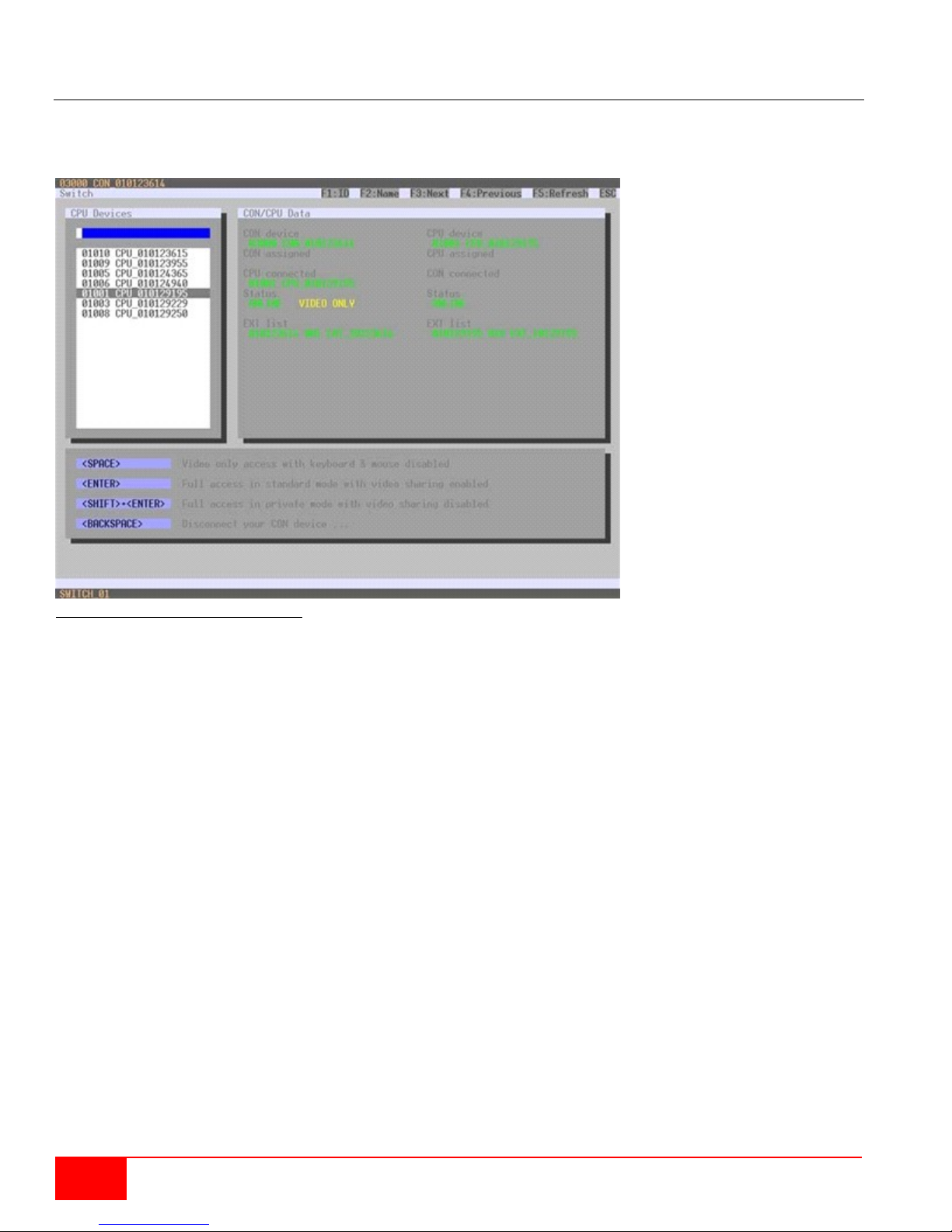
KVM Switching
KVM Switching of the user’s own console can be performed only through the OSD.
Select Switch in the main menu.
Figure 66. KVM Switching through OSD
To switch the console to any available CPU, proceed as follows:
1. Select from the CPU Devices list on the left side the one to be connected to the CON device.
2. Confirm the desired connection type with the appropriate keybo ar d c om mand.
Switching operations from the CON device can only be done to CPU devices that are available in the CPU
Devices list.
76
Orion XC Installation and Operations Manual
Page 85
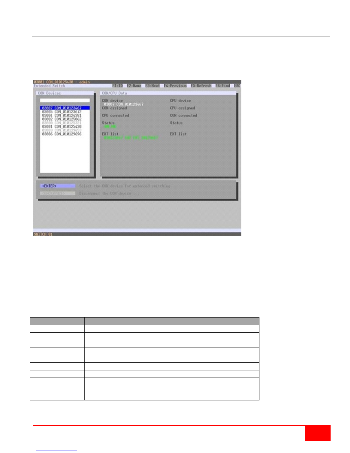
Field
Description
CON device
Assigned physical extender unit (CON unit)
CON assigned
Virtual CON Device that is assigned to the real CON device
CPU connected
Currently connected CPU device
CON status
Current connection status (CON device)
EXT list
List of all available physical extender units (CON units)
CPU device
Assigned physical extender unit (CPU unit)
CPU assigned
Real CPU device that is assigned to a virtual CPU device
CON connected
Currently connected CON device
CPU status
Current connection status (CPU device)
EXT list
List of all available physical extender units (CPU units)
Extended Switching
Extended switching of any console to any CPU can be performed through the OSD or the Java Tool.
Exended Switching through the OSD
To switch any console to any available CPU, proceed as follows:
Select Extended Switch in the main menu.
Figure 67. Extended KVM Switching through OSD
1. Select from the CON Devices list on the left side the one to be should be switched to a CPU
device and open it by pressing <Enter>.
2. Select from the CPU Devices list on the left side the one to be connected to the open CON device.
3. Confirm the desired connection type with the appropriate keyboard command.
Switching operations for a given CON device can only be done to CPU devices that are available in the
CPU Devices list.
The following information is shown in this menu:
Orion XC Installation and Operations Manual
77
Page 86
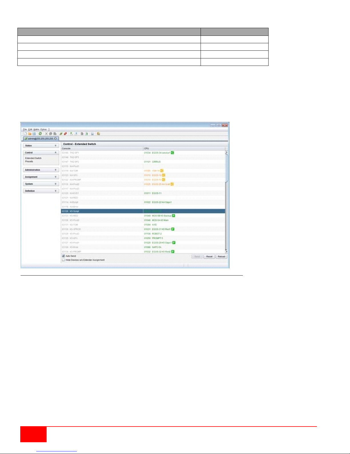
Function
Keyboard Command
Set a video only connection.
<Space>
Set a KVM connection.
<Enter>
Set a KVM connection in private mode (video sharing disabled).
<Shift> + <Enter>
Disconnect the CON device from the CP U de vice.
<Backspace>
Select between the following switching functions:
KVM Switching through the Java Tool
There are two methods to perform switching operations for the Orion XC via the Java Tool, as described
below.
Method 1:
Select Control > Extended Switch in the task area.
Figure 68. Extended KVM Switching through Java Tool - Method 1 (from Extended Switch Option)
All connected consoles and their CPU connections are shown in columns in the working area in this menu.
Switching operations can only be performed in online mode. This means an active network connection
between the matrix and the Java Tool is needed.
To set a KVM connection between a console and a CPU, double-click on the corresponding selection
box within the Full Access column and select the requested CPU.
To set a video connection between a console and a CPU, double-click on the corresponding selection
box within the Video Only column and select the requested CPU.
To set a Private Mode connect ion between a console and a CPU, double-click on the corresponding
selection box within the Private Mode column and select the requested CPU.
Note: CPUs whose respective console does not have access rights, will not appear in the list.
78
Orion XC Installation and Operations Manual
Page 87
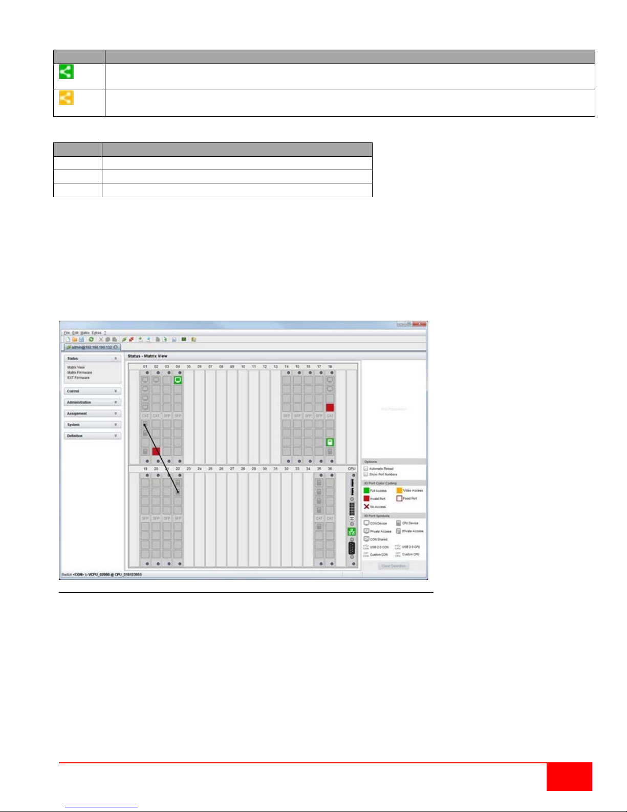
The following symbols are shown in the connection overview:
Symbol
Description
CON device is connected via Shared Access with at least one additional console to the same
CPU. The CON device has Full Access at the moment.
CON device is connected via Shared Access with at least one additional console to the same
CPU. The CON device has a Video Access connection at the moment.
Button
Function
Send
Send desired switching operations to the matrix
Reset
Disconnect all existing connections within the matrix
Reload
Reload switching status list
Use the following button to perform a switching operation:
By activating the Auto Send function in the left lower corner of the working area, switching operations will
be done immediately without needing to confirm by pressing the Send button.
By activating the Hide Devices w/o Extender Assignment function in the left lower corner of the working
area, only those CON and CPU devices assigned to an extender are shown.
Method 2:
Select Status > Matrix View in the task area.
Figure 69.Extended KVM Switching through Java Tool - Method 2 (from Matrix View Option)
To perform switching operations between CON and CPU devices proceed as follows:
1. Move the mouse cursor to the port that has to be switched.
2. Hold down the left mouse button and move the cursor to the port that has to be connected to the
initial port. The cursor movement will be indicated as a black auxiliary line.
3. Release the left mouse button. A popup to select the available switching type (Full Access, Video
Access or Private Mode) will be opened.
4. Select the desired switching type. The switching operation will be immediately executed. At the
same time all extender units that are assigned to the involved devices will be switched.
Note: If there is a red X on a port when switching by using the Matrix View, the console to be connected
does not have access rights to the CPU at that port.
Orion XC Installation and Operations Manual
79
Page 88

To disconnect an existing connection between CON and CPU devices proceed as follows:
1. Click on the port that has to be disconnected by using the right mouse button.
2. Select the Disconnect function in the popup that appears. The connected ports will be
disconnected immediately. At the same time any other connections of extenders assigned to the
involved devices will be disconnected.
USB 2.0 Switching
Switching of USB 2.0 extenders basically works like switching of KVM extenders. There are two
possibilities for switching USB 2.0 extenders, depending on how the extenders are set up in the Matrix.
1. USB 2.0 extenders that were created and assigned to an existing device with KVM extender units.
2. USB 2.0 extenders that were created as a separate device which contains no KVM extender units.
This allows switching of USB 2.0 equipment independent of KVM devices.
Notes:
The separate switching of USB 2.0 signals requires the methods described in the section on
Extended Switching above.
When switching USB 2.0 equipment, wait until the CPU enumeration of USB 2.0 devices has been
completed before switching to the next CPU (approximately. 5-15 seconds). Failure to allow
enough time for USB 2.0 device enumeration can negatively affect the stability of the connection.
80
Orion XC Installation and Operations Manual
Page 89
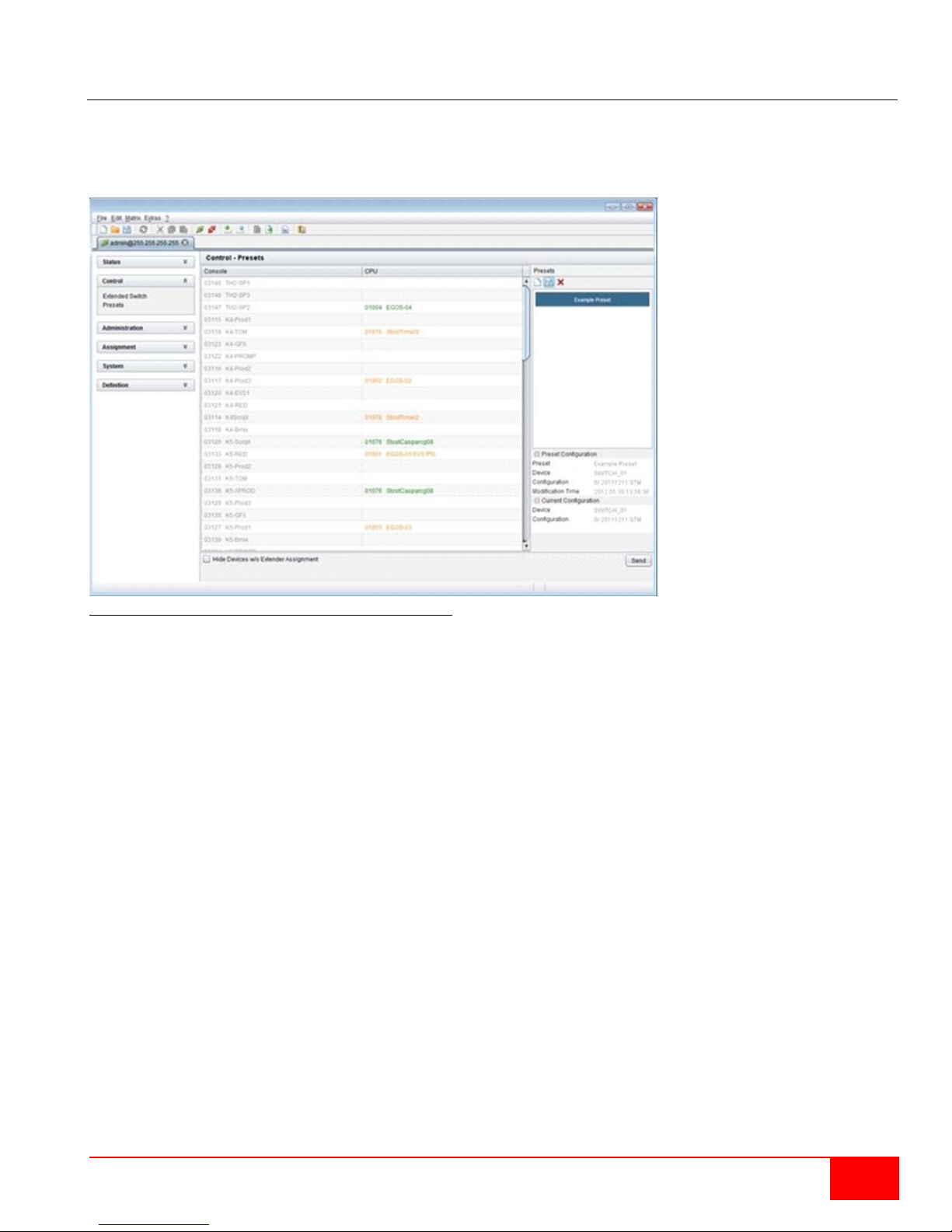
Presets
Predefined macros to switch the matrix without loading a new configuration can be created and activated
in this menu. This menu can only be accessed from the Java Tool.
Select Control > Presets in the task area.
Figure 70. Setting up Macro Presets through the Java Tool
To create a new switch macro proceed as follows:
1. Open a new switch macro by pressing on the New symbol in the right column of the work ing area.
You will be asked whether the the new macro should be based on the existing connection.
2. Select the switching operations desired in the corresponding columns (Full Access, Video Only or
Private Mode) by using a double click on the respective selection box or use the function for a
disconnect (Disconnect CPU).
3. Save the switch macro by clicking the symbol Save in the right column of the working area. A save
dialog will be opened.
4. Enter a name or the new switch macro and confirm by pressing the Ok button in the save dialog.
5. By clicking on a selected switch macro with the right mouse button, a copy of the current switch
macro can be created using the Save as... option.
6. Already saved macros can be deleted by pressing the Delete symbol.
To invoke a previously defined switch macro, proceed as follows:
1. Select the switch macro to be loaded in the right column of the working area.
2. Activate the selected switch macro by pressing the Send button on the bottom right of the working
area.
Only switch macros that are compliant with the hardware and the configuration of the current matri x can
be executed.
Orion XC Installation and Operations Manual
81
Page 90

Serial Interface
The Orion XC allows switching via a serial interface (RS232).
Detailed information for the serial interface and the corresponding switching commands are available in
form of an API (application programming interface) upon request.
Power Up and Power Down Functions
This section deals with Power functions of the Orion XC.
Restart
The Orion XC can be restarted through the OSD and the Java Tool.
Restarting through the OSD
1. Select Configuration > Restart Matrix or Restart IO Board in the main menu to restart either the
matrix or the I/O boards.
2. Confirm the selection with button YES.
The matrix and the I/O boards will be restarted with the current settings.
Restarting through the Java Tool
Select Matrix > Res t a r t Matrix in the menu bar.
The Orion XC will be restarted with the current settings.
Factory Reset
It is only possible to reset the system to factory defaults through the OSD.
When a factory reset is done, all cur rent settings and all configurations stored in the matrix will be lost.
This also applies to the network parameters (reset to DHCP) and the admin password.
If a firmware update has been done since the delivery, the matrix will be set to the defaults defined in that
firmware.
Resetting through the OSD
1. Select Configuration > Factory Reset in the main menu.
2. Confirm the selection with the YES button.
The Orion XC will be reset to factory settings.
Power Down
Press the on/off rocker switch at the main sockets of the power supply units to start up or power down
the matrix.
82
Orion XC Installation and Operations Manual
Page 91
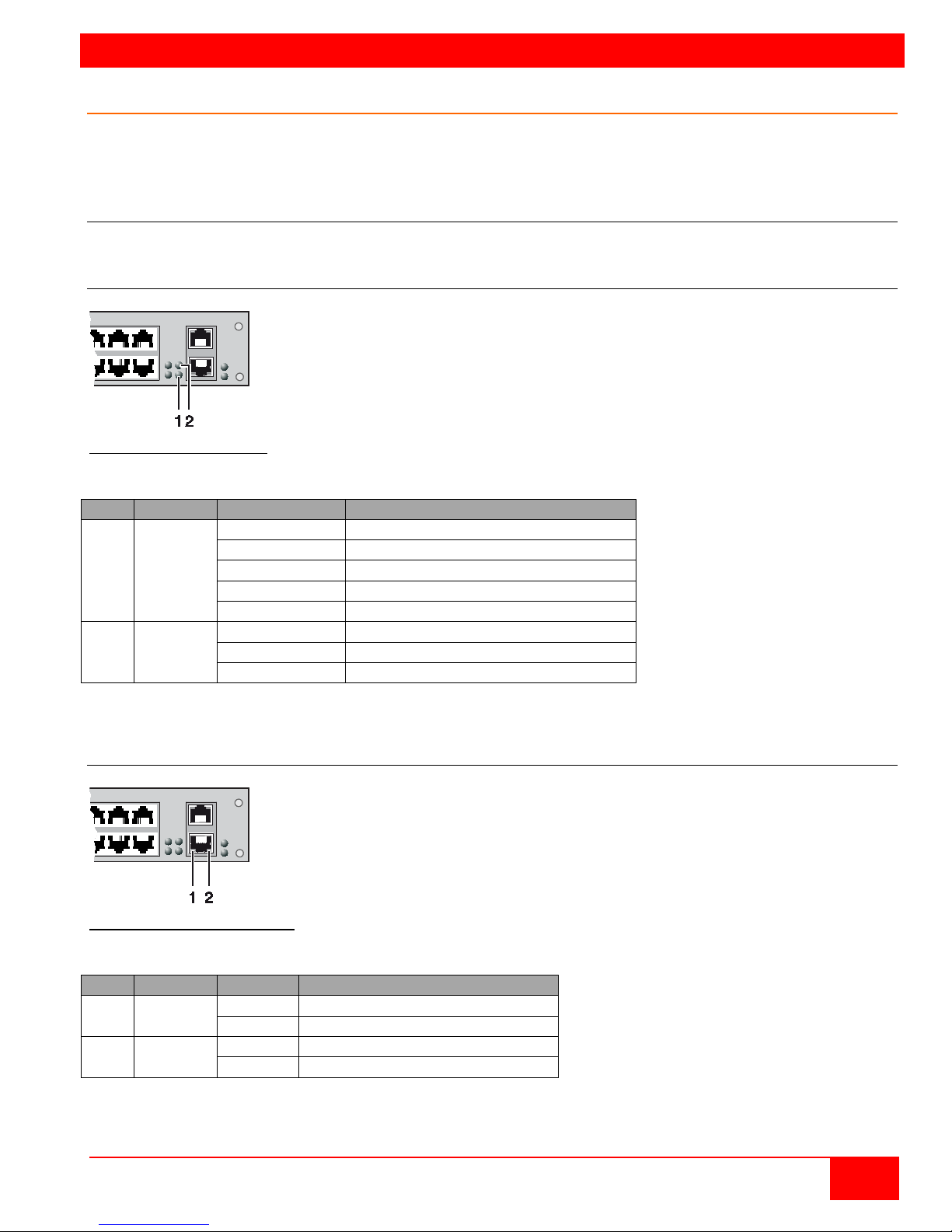
STATUS INDICATORS
Pos.
LED
Status
Description
1
Status 1
White
CPU board is in registration process
Blue flashing
Registration at the matrix is started
Red flashing
Registration in progress
Green flashing
Operating condition
Green
CPU board de-registered
2
Status 2
White
CPU board is in registration process
Red flashing
Registration at the matrix is started
Off
Operating condition
Pos.
LED
Status
Description
1
Status 1
(orange)
On
Connection to network available
Off
No connection to network
2
Status 2
(green)
Flashing
Data traffic active
Off
Data traffic not active
Diagnostics and Status
This section describes the diagnostics that are available on the Orion XC. Status indicators, both
physically on the unit as LED indicators, and in the software, are discussed here.
Status LEDs
The Orion XC components are fitted with the following LEDs for overall status indication.
CPU
Figure 71. CPU Status LEDs
Status LEDs for CPU
Due to variations in LED type "white" might also appear as light purple or light blue.
Lan Port
Figure 72. LAN Port Status LEDs
Status LEDs on the LAN Port:
Orion XC Installation and Operations Manual
83
Page 92
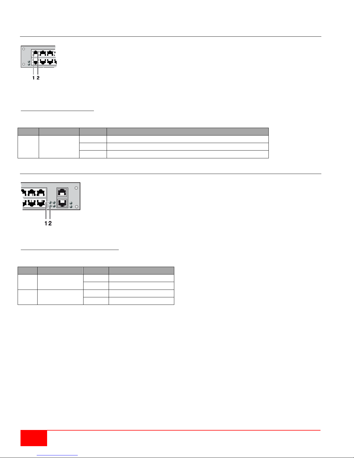
1 → Link Status Port 1
2 → Link Status Port 2
Pos.
LED
Status
Description
1 & 2
Link Status
Off
Initialization
Green
Connection via interconnect cable ok, data traffic active
Orange
Extender not recognized
Pos.
LED
Status
Description
1
Status PSU 1
(green)
On
Operating condition
Off
Power supply unit off
2
Status PSU 2
(blue)
On
Operating condition
Off
Power supply unit off
I/O Ports Status LEDs
Figure 73. I/O Port Status LEDs
Status LEDs at the ports of the I/O boards:
Power Supply Unit
1 → Power supply unit 1 status LED
2 → Power supply unit 2 status LED
Figure 74. Power Supply Unit Status LEDs
Status LEDs of the Power Supply Units:
84
Orion XC Installation and Operations Manual
Page 93
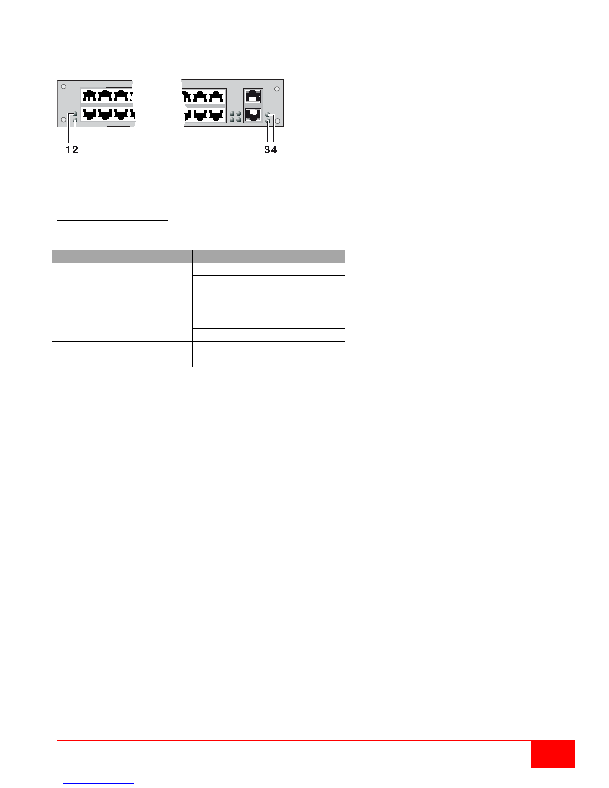
Pos.
LED
Status
Description
1
Left Fan Status 1
(red)
On
Error Indication
Off
Operating Condition
2
Left Fan Status 2
(red)
On
Operating Condition
Off
Fan Off
3
Right Fan Status 2
(green)
On
Operating Condition
Off
Fan Off
4
Right Fan Status 1
(red)
On
Error Indication
Off
Operating Condition
Fan Status LEDs
1 → Left fan status LED 1
2 → Left fan status LED 2
3 → Right fan status LED 2
4 → Right fan status LED 1
Figure 75. Fan Status LEDs
Status LEDs of the fan trays:
Orion XC Installation and Operations Manual
85
Page 94
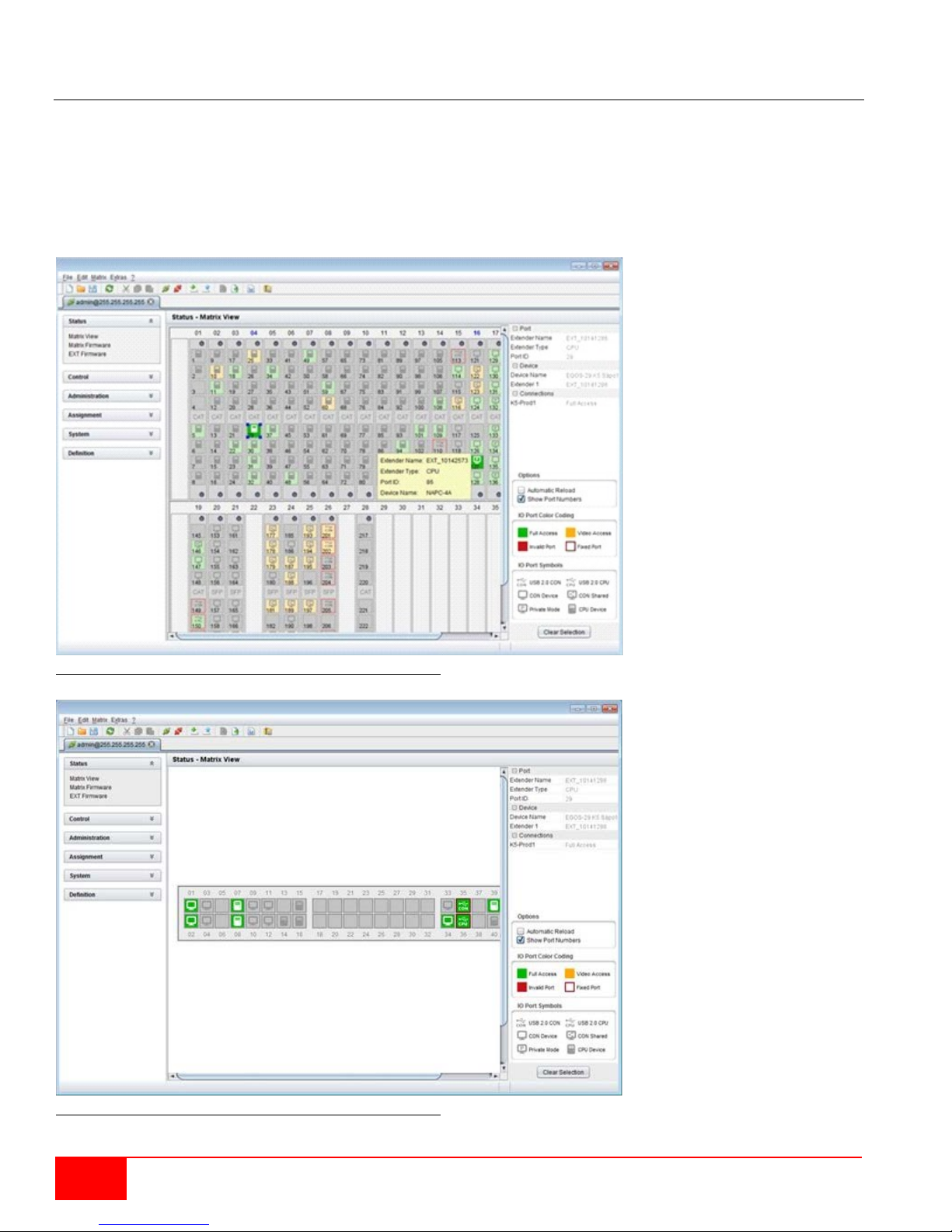
Port Status
The connections and the switching status between the various consoles and CPUs are shown in this
menu. This menu can only be accessed from the Java Tool.
Viewing Port Status with the Java Tool
The current port configuration of the Orion XC is illustrated in this menu.
Select Status > Matrix View in the task area in online mode.
Figure 76. Viewing Port Status with the Java Tool (Example 1)
Figure 77. Viewing Port Status with the Java Tool (Example 2)
86
Orion XC Installation and Operations Manual
Page 95
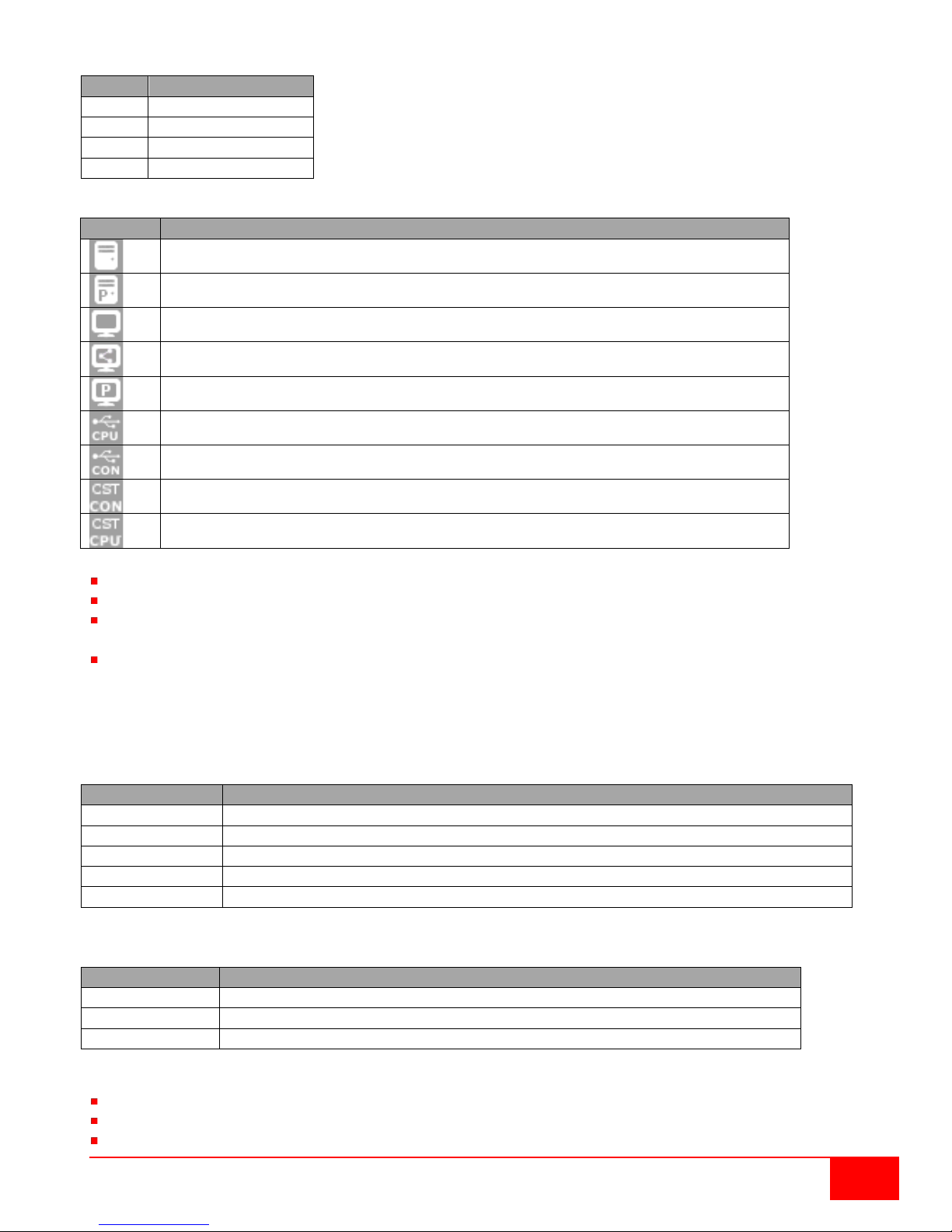
The colors indicates the connection status:
Color
Description
Grey
Port not connected
Yellow
Video connection
Green
KVM connection
Red
Faulty Port
Symbol
Description
Field
Description
Extender Name
Name of the selected extenders
Extender Type
Type of the selected extender
Port ID
Number of the selected port
Device Name
Name of the connected console or CPU
Connections
Listing of assigned connections to the marked port (Full Access or Video Access)
Function
Description
Open Extender
The menu for definition of the currently selected extender is opened
Open Device
The menu for definition of the currently selected console or CPU is opened
Switch
The menu for execution of switching operations is opened
The symbol indicates the extender that is recognized and defined at a certain port:
Port connected to a CPU unit
Port is connected to a CPU unit that is switched to a CON unit in Private Mode
Port connected to a CON unit
Port connected to a CON unit with Shared Access to a CPU.
Port is connected to a CON unit that is switched to a CPU unit in Private Mode
Port connected to an USB 2.0 CPU unit
Port connected to an USB 2.0 CON unit
Port is configured as a CON port for customer specific applications
Port is configured as a CPU port for customer specifiv applications
Red framed ports are defined as "fixed" (e. g. for USB 2.0 connections)
The port with a static blue frame is currently selected.
If a port is selected, all the other ports will be shown transparent except those that are connected to the
currently selected port. A selection can be cleared by pressing the Clear Selection button.
If a red X is shown on a port when attempting to switch with Matrix View, the console to be connected
does not have access rights to the CPU at that port.
To show the extender information of the currently selected port on the right side of the working area,
press the left mouse button.
The following information is available:
To open the context menu for the currently selected port with further functions, press the right mouse
button. The following context functions are available:
The Matrix View can be reloaded using the following means:
Press the <F5> key of a connected keyboard
Execute Edit > Reload in the menu bar
Press the Reload button in the tool bar
Orion XC Installation and Operations Manual
87
Page 96
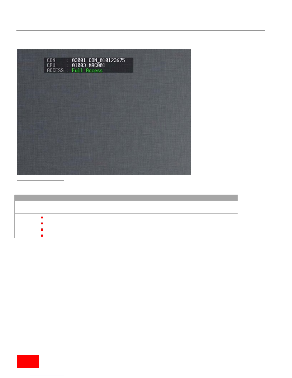
Extender OSD
Field
Description
CON
Name of the console
CPU
Name of the currently connected CPU
Access
Full Access: The console has a KVM connection to the displayed CPU.
not connected: The console is not connected to a CPU.
All extenders used with the Orion XC are provided with their own OSD to display the connection status of
their console.
Figure 78.Extender OSD
The following information is shown in the OSD information screen:
Video Access: The console has a video only connection to the displayed CPU.
Private Mode: The console has a Private Mode connection to the displayed CPU.
Note: If the Mouse Connect or Keyboard Connect options are used, the name of the console with
keyboard / mouse control will be displayed at those consoles that do not have K/M control at the moment.
The console is displayed in yellow color under Access.
88
Orion XC Installation and Operations Manual
Page 97
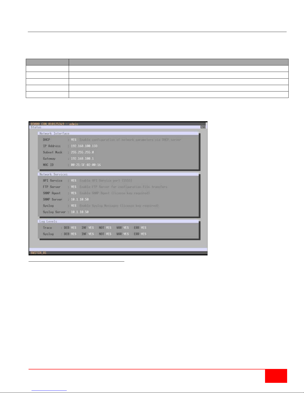
Network Status
Field
Description
DHCP
Allow the network to dynamically assign network settings. Display YES or NO
IP Address
Information about the IP address, whether provided manually or via DHCP
Subnet Mask
Information about the subnet mask as provided manually or via DHCP
Gateway
Information about the gateway address as provided manually or via DHCP
MAC ID
Information about the MAC address in the matrix
The current network configuration is shown in this menu. This menu can be accessed through the OSD or
the Java Tool.
The following information is shown in this menu:
Viewing Network Status through the OSD
Select Status > Network in the main menu.
Figure 79. Viewing Network Status through OSD
Orion XC Installation and Operations Manual
89
Page 98
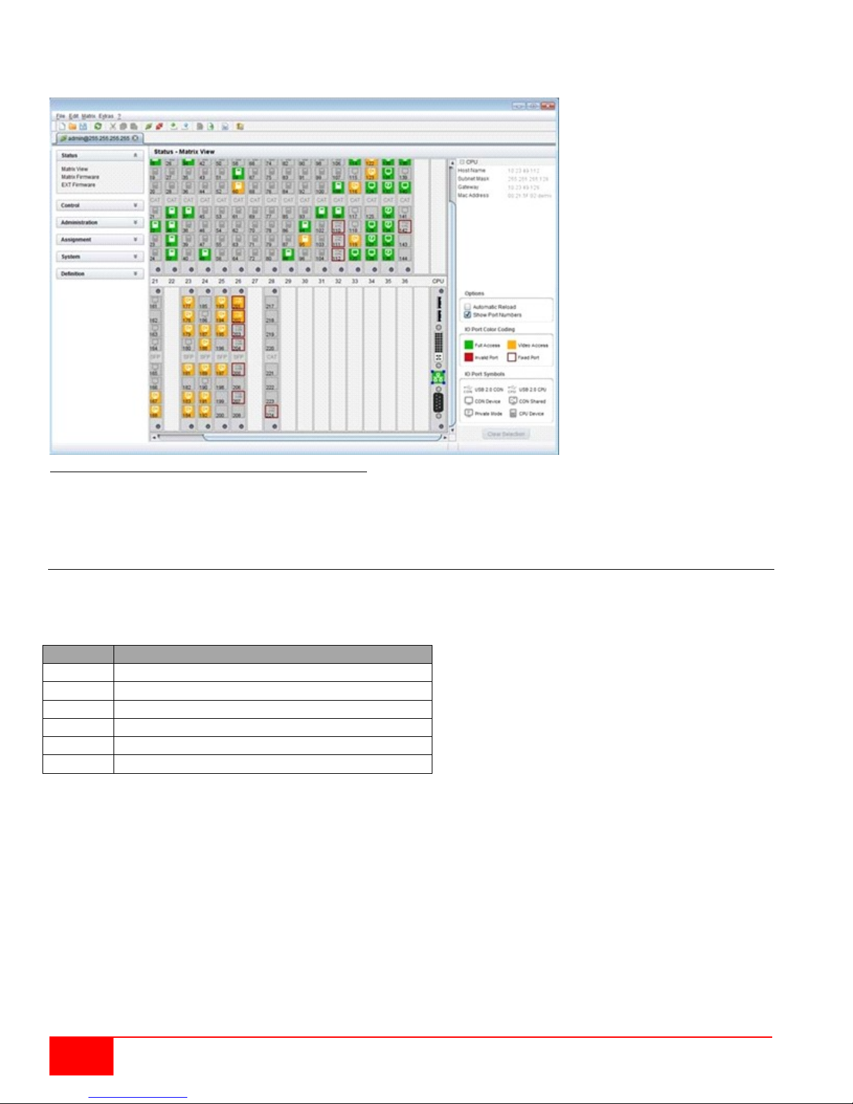
Field
Description
Name
Description of the modules
Type
Type number
Ports
Number of ports
Version
Complete description of the firmware version
Date
Date of the firmware version
Status
Module status
Viewing Network Status through the Java Tool
Select Status > Matrix View in the task area.
Figure 80. Viewing Network Status through the Java Tool
Use the left mouse button to click on the network port of the CPU board. The corresponding network
status will be shown on the right side of the working area.
Firmware Status Matrix
The current firmware status of the installed boards is shown in this menu. This menu can be accessed
through the OSD or the Java Tool.
The following information is shown in this menu:
90
Orion XC Installation and Operations Manual
Page 99
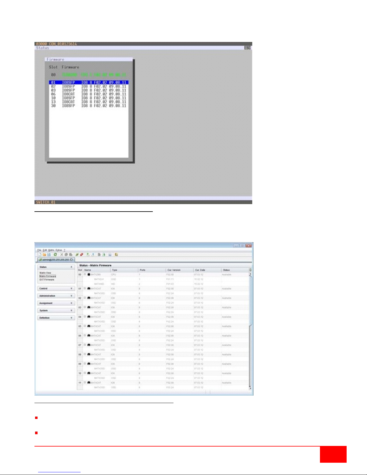
Viewing Firmware Status through the OSD
Select Status > Firmware in the main menu.
Figure 81. Viewing Firmware Status through OSD
Viewing Firmware Status through the OSD
Select Status > Matrix Firmware in the task area.
Figure 82. Viewing Firmware Status through the Java Tool
To read out the firmware status and store it locally (file extension .dtf), select Matrix > Save Firmware
Status to File...
To read out the overall status of the matrix and store it locally (file extension .zip), select Matrix > Save
Status to File... or press the respective button in the symbol bar.
Orion XC Installation and Operations Manual
91
Page 100
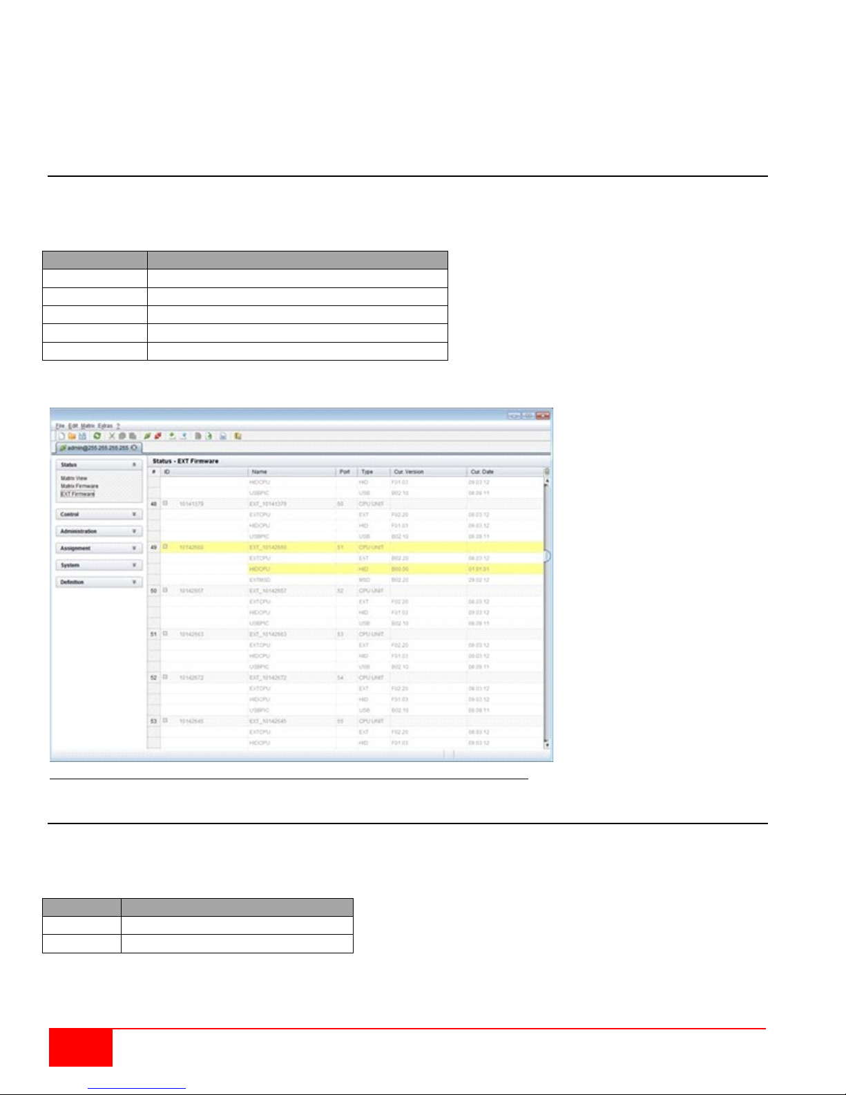
Field
Description
Name
Description of the firmware
Type
Description of the extender module
Ports
Number of ports
Cur. Version
Description of the current firmware version
Cur. Date
Date of the current firmware version
Field
Description
Time
Timestamp
Message
Detailed description of the event
The various modules can expanded and contracted in the Name column by clicking with the left mouse
button on the plus or minus symbols to get a better overview.
By clicking with the left mouse button on the plus or minus symbol in the upper r ig ht corner of the working
area, all module inf ormation can be expanded and contracted.
Firmware Status Extender
The current firmware status of the connected extenders is shown in this menu. This menu can be accessed
from the Java Tool.
The following information is shown in this menu:
Select Status > EXT Firmware in the task area.
Figure 83. Viewing Firmware Status on the connected Extenders through the Java Tool
Trace Function
All events, e.g. activities and switching operations of the Orion XC matrix, are logged and displayed in this
menu. This function is used for diagnostic purposes. This menu can be accessed only from the OSD
The following information is shown in this menu:
Trace Options
Select Status > Trace IO Board in the main menu to check the events on the current I/O boards.
Select Status > Trace Matrix to check the matrix events.
92
Orion XC Installation and Operations Manual
 Loading...