

Page 1
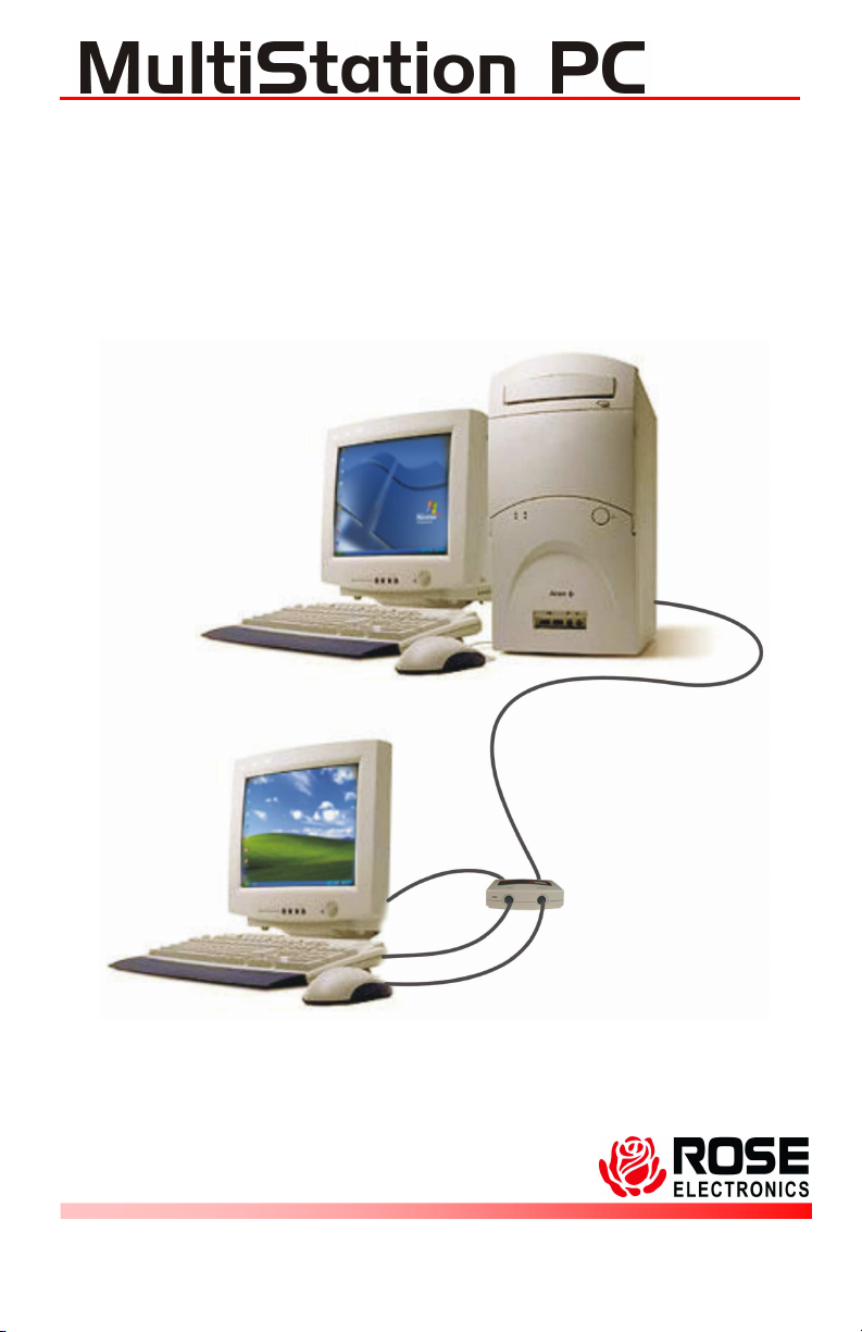
PC SHARING SYSTEM
INSTALLATION AND OPERATIONS
MANUAL
10707 Stancliff Road Phone: (281) 933-7673
Houston, Texas 77099 WWW.ROSE.COM
Page 2

LIMITED WARRANTY
Rose Electronics
date of purchase from Rose Electronics or an authorized dealer. Should this product fail to be in good
working order at any tim e during this one-year warranty period, Rose Electronics will, at its option,
repair or replace the Unit as set forth below. Repair parts and replacement units will be either
reconditioned or new. All replaced parts becom e the property of Rose Electronics. This limited
warranty does not include service to repair damage to the Unit resulting from accident, disaster,
abuse, or unauthorized modification of the Unit, including static discharge and power surges.
Limited Warranty servic e may be obtained by delivering this unit during the one-year warranty period
to Rose Electronics or an authorized repair center providing a proof of purchase date. If this Unit is
delivered by mail, you agree to insure the Unit or assume the risk of loss or damage in transit, to
prepay shipping charges to the warranty service location, and to use the original shipping container or
its equivalent. You must call for a return authorization number first. Under no circumstances will a unit
be accepted without a return authorization number. Contact an authorized repair center or Rose
Electronics for further information.
ALL EXPRESS AND IMPLIED WARRANTIES FOR THIS PRODUCT INCLUDING THE
WARRANTIES OF MERCHANTABILITY AND FITNESS FOR A PARTICULAR PURPOSE, ARE
LIMITED IN DURATION TO A PERIOD OF ONE YEAR FROM THE DATE OF PURCHASE, AND NO
WARRANTIES, WHETHER EXPRESS OR IMPLIED, WILL APPLY AFTER THIS PERIOD. SOME
STATES DO NOT ALLOW LIMITATIONS ON HOW LONG AN IMPLIED WARRANTY LASTS, SO
THE ABOVE LIMITATION MAY NOT APPLY TO YOU.
IF THIS PRODUCT IS NOT IN GOOD WORKING ORDER AS WARRANTIED ABOVE, YOUR SOLE
REMEDY SHALL BE REPLACEMENT OR REPAIR AS PROVIDED ABOVE. IN NO EVENT W ILL
ROSE ELECTRONICS BE LIABLE TO YOU FOR ANY DAMAGES INCLUDING ANY LOST
PROFITS, LOST SAVINGS OR OTHER INCIDENTAL OR CONSEQUENTIAL DAMAGES ARISING
OUT OF THE USE OF OR THE INABILITY TO USE SUCH PRODUCT, EVEN IF ROSE
ELECTRONICS OR AN AUTHORIZED DEALER HAS BEEN ADVISED OF THE POSSIBILITY OF
SUCH DAMAGES, OR FOR ANY CLAIM BY ANY OTHER PARTY.
SOME STATES DO NOT ALLOW THE EXCLUSION OR LIMITATION OF INCIDENTAL OR
CONSEQUENTIAL DAMAGES FOR CONSUMER PRODUCTS, SO THE ABOVE MAY NOT APPLY
TO YOU. THIS WARRANTY GIVES YOU SPECIFIC LEGAL RIGHTS AND YOU MAY ALSO HAVE
OTHER RIGHTS WHICH MAY VARY FROM STATE TO STATE.
NOTE: This equipment has been tested and found to comply with the limits for a Class B digital
device, pursuant to Part 15 of the FCC Rules. These limits are designed to provide reasonable
protection against harmful interference when the equipment is operated in a commercial environment.
This equipment generates, uses, and can radiate radio frequency energy and, if not installed and used
in accordance with the instruction manual, may cause harmful interference to radio communications.
Operation of this equipm ent in a residential area is likely to cause harmful interference in which case
the user will be required to correct the interference at his own expense.
IBM, AT, and PS/2 are trademarks of International Business Machines Corp. Microsoft and Microsoft
Windows are registered trademarks of Microsoft Corp. Any other trademarks mentioned in this
manual are acknowledged to be the property of the trademark owner.
®
warrants the MultiStation PC™ to be in good working order for one year from the
Copyright Rose Electronics 2004. All rights reserved.
No part of this manual may be reproduced, stored in a retrieval system, or transcribed in any form or any
means, electronic or mechanical, including photocopying and recording, without the prior written permission
of Rose Electronics.
Rose Electronics Part # MAN-MSXP
Printed In the United States of America - Revision 1.6
Page 3

FCC/IC STATEMENTS, EU DECLARATION OF CONFORMITY
5: 1995
FEDERAL COMMUNICATIONS COMMISSION
AND INDUSTRY CANADA
RADIO-FREQUENCY INTERFERENCE STATEMENTS
This equipment generates, uses and can radiate radio frequency
energy and if not installed and used properly, that is in strict
accordance with the manufacturer’s instructions may cause
interference to radio communication. It has been tested and found to
comply with the limits for a Class B digital device in accordance with
the specifications of Part 15 of FCC rules, which are designed to
provide reasonable protection against such interference when the
equipment is operated in a commercial environment. Operation of this
equipment in a residential area is likely to cause interference, in which
case the user at his own expense will be required to take whatever
measures may be necessary to correct the interference.
Changes or modifications not expressly approved by the party
responsible for compliance could void the user’s authority to operate
the equipment.
This digital apparatus does not exceed the Class B limits for radio
noise emission from digital apparatus set out in the Radio Interference
Regulation of Industry Canada.
Le présent appareil numérique n’émet pas de bruits radioélectriques
dépassant les limites applicables aux appareils numériques de la
classe B prescrites dans le Règlement sur le brouillage radioélectrique
publié par Industrie Canada.
EUROPEAN UNION DECLARATION OF CONFORMITY
ACCORDING TO COUNCIL DIRECTIVE 89/336EEC & 73/23EEC
This equipment is in conformity with the
protection requirements of the following
Council Directives:
The Declaration of Conformity is based upon
compliance of the product with the following
harmonized standards:
EN55022: 1998 EN61000-4EN55024: 1998 EN61000-4-6: 1996
EN61000-4-2: 1995 EN61000-4-11: 1994
EN61000-4-3: 1995 EN60950: 2000
EN61000-4-4: 1995
Page 4

TABLE OF CONTENTS
Contents
Disclaimer .......................................................................................... 1
System introduction............................................................................ 1
Features........................................................................................ 2
Compatibility.................................................................................. 3
Package contents.......................................................................... 3
Hardware ........................................................................................... 4
Cables................................................................................................ 5
Installation.......................................................................................... 6
Pre-installation requirements.......................................................... 6
Installing the PCI card.................................................................... 7
Installing the Remote user module................................................. 8
Applying power.............................................................................. 8
Installing the software.................................................................... 9
User Operation..................................................................................12
Service Information............................................................................16
Maintenance and Repair...............................................................16
Technical Support.........................................................................16
Safety................................................................................................17
Figures
Figure 1. Hardware............................................................................. 4
Figure 2. PCI card .............................................................................. 7
Figure 3. Remote user module............................................................ 8
Figure 5. Software license agreement................................................. 9
Figure 6. User information .................................................................10
Figure 7. Destination folder................................................................10
Figure 8. Installation successful .........................................................11
Figure 9. Console window..................................................................12
Figure 10. Station Properties .............................................................13
Figure 11. Station options..................................................................13
Figure 12. Start/Stop window.............................................................14
Figure 13. Test screen.......................................................................14
Figure 14. Broadcast message screen...............................................15
Figure 15. Message box ....................................................................15
Appendices
Appendix A. General specifications....................................................21
Appendix B. Parts and cables............................................................22
Page 5

INTRODUCTION
Disclaimer
While every precaution has been taken in the preparation of this
manual, the manufacturer assumes no responsibility for errors or
omissions. Neither does the manufacturer assume any liability for
damages resulting from the use of the information contained herein.
The manufacturer reserves the right to change the specifications,
functions, or circuitry of the product without notice.
The manufacturer cannot accept liability for damages due to misuse of
the product or other circumstances outside the manufacturer’s control.
The manufacturer will not be responsible for any loss, damage, or
injury arising directly or indirectly from the use of this product.
System introduction
Thank you for choosing the Rose Electronics MultiStation PC. The
MultiStation PC is the result of Rose Electronics commitment to
providing state-of-the-art solutions for today’s demanding workplace.
The MultiStation PC has proven to be a valuable investment for any
business, home, or office that has a need to share a common computer
between two or more users.
The MultiStation PC system consists of two Units, a PCI card and the
remote user module. The PCI card installs in an unused PCI slot in the
computer being shared. The remote user module connects to a
keyboard, monitor, and mouse. The PCI card and remote user module
are connected together with industry standard CAT-5 shielded, solid
core twisted-pair cable terminated with RJ45 connectors.
Using the MultiStation PC to expand the use of a common computer
has several advantages that make it convenient for the users. With the
MultiStation PC you get all the benefits of a second computer without
the expense of purchasing another computer. Each user can work
independently on the same or different application. One user can be
updating the company’s financials and another user developing a
software application with no interference. Each user can have their own
Windows desktop, and share peripheral devices like printers, plotters,
and scanners.
Users can share a common modem and both connect and surf the web
or send and receive E-mail over a single phone or DSL line with a
single Internet connection. In a network environment, both users can
share the PC’s network adapter and connection.
MULTISTATION PC INSTALLATION AND OPERATIONS MANUAL
1
Page 6

Features
With the MultiStation PC you get all the benefits of a second
computer without the expense of purchasing another computer.
Allows multiple users to use one computer at the same time.
Video resolution up to 1280 x 1024 x 16 bit High Color at 60 Hz
Each user can work independently on the same or different
application with no interference.
Virtually no performance degradation
Each user can have their own Windows desktop
Share peripheral devices like printers, plotters, and scanners.
Users can share a common modem and connect to the Internet.
They can surf the web or send and receive E-mail over a single
phone or DSL line with a single Internet connection
Locate the second user up to 50 feet away from the PC using
standard STP CAT5 cable.
In a network environment, all users can share the PC’s network
adapter and connection.
Saves equipment cost, software cost, peripherals, networking, and
other hardware costs.
Easy to install and maintain.
1024 x 768 x 32 bit True Color at 85Hz
2
MULTISTATION PC INSTALLATION AND OPERATIONS MANUAL
Page 7

Compatibility
Computers
PC compatible running Windows
or Windows 2000 (SP2)
P3 or higher computer, Athlon AMD, Intel Celeron,
and Intel, 848P + Chipsets.
Ram 256 MB Ram + 256 MB per additional user
Monitors VGA to UXGA
Keyboards PS/2
Mouse PS/2
xp
(SP1 & SP2)
Package contents
The package contents consist of the following:
The MultiStation PC PCI card
Remote user module
MultiStation PC installation software (CD)
15 feet of STP CAT5 cable
Installation and operations manual
If the package contents are not correct, contact Rose Electronics or
your reseller, so the problem can be quickly resolved.
Rose Electronics web site
Visit our web site at www.rose.com for Multi-Station PC product
software updates and additional information on other products that are
designed for data center applications, classroom environments and
other applications.
About this manual
This manual covers the installation and operation of the
MultiStation PC model.
Registration
Register your copy for future updates by registering at:
http://www.rose.com/htm/multistationpc-online-registration.htm
MULTISTATION PC INSTALLATION AND OPERATIONS MANUAL
3
Page 8
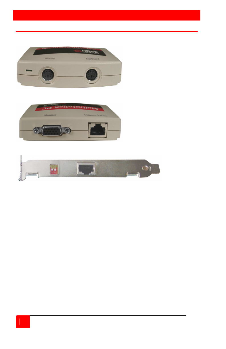
HARDWARE
Hardware
Front
Remote
user
module
Figure 1. Hardware
Connectors:
Front
MiniDin-6 PS/2 keyboard
MiniDin-6 PS/2 mouse
Rear
RJ45 CAT5 cable connection
HD15M VGA monitor connection
PCI card
RJ45 CAT5 cable connection
Dip Switch Configuration setting switches
Rear
Remote
user
module
PCI card
4
MULTISTATION PC INSTALLATION AND OPERATIONS MANUAL
Page 9
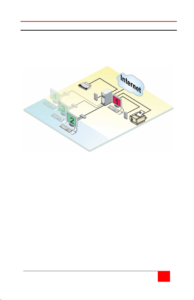
Local User
Cables
PC to Remote user module
The PCI cards RJ45 connector is connected to the Remote user
module with up to 15 feet of standard CAT5 STP “solid core” cable
terminated with RJ45 connectors (included). Rose Electronics cable
part number CAB-08STPnnn. The maximum length of CAT5 cable that
should be used is 50 feet (optional).
Remote User
Module
MULTISTATION PC INSTALLATION AND OPERATIONS MANUAL
5
Page 10

INSTALLATION
Installation
Please refer to the safety section first before proceeding with any
installation or configuration of the MultiStation PC.
Installation of the MultiStation PC is an addition to the Windows XP or
Windows 2000 operating system and must be performed correctly.
Due to the variations in computer systems, installation of the
MultiStation PC on non-approved hardware may require assistance.
Please follow the instructions step by step to insure proper installation.
Pre-installation requirements
The following items must be performed prior to installing the hardware
or software. Since the installation is an addition to the operating
system, these items must be completed prior to installation.
1. It is recommended that the PC have the following:
a. Minimum of 256 MB of RAM per user
b. Pentium III processor or higher
c. Athlon, Intel Celeron, and Intel 848P + Chipsets
2. Windows XP installed as the operating system with Windows XP
Service Pack 1 or higher installed or Windows 2000 installed with
Service Pack 2 installed.
See the troubleshooting section if problems occur after installation is
completed.
Installation of the MultiStation PC consists of the following four steps.
Make sure that the computer is powered down and unplugged from the
main electrical outlet.
1. Installing the MultiStation PC’s PCI card
2. Connecting a keyboard, monitor, and mouse to the remote user
module and connecting it to the MultiStation PC’s PCI card with
CAT5 cable
3. Applying power
4. Installing the software
6
MULTISTATION PC INSTALLATION AND OPERATIONS MANUAL
Page 11
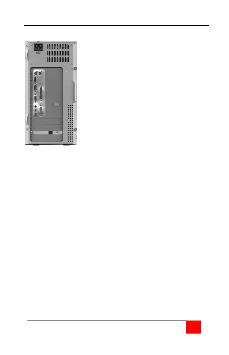
Installing the PCI card
Figure 2. PCI card
Note: The two dipswitches located on the MultiStation PC’s PCI card
should initially be in the “OFF” position (Default shipped position). If
the dipswitches are not in the “OFF” position, set them both to the
“OFF” position before applying any power.
DO NOT install additional cards and remote user modules at this time.
Complete the installation for one and have one user fully operational
before installing additional cards.
Ground yourself to a grounded metal
object before installing the PCI card
1. Remove the computer cover and
locate an un-used PCI slot on the
motherboard
2. Install the MultiStation PC PCI card
in the PCI slot by firmly applying
uniform pressure on the top of the
card until it seats properly in the
PCI slot
3. Secure the PCI card with the
proper size screw
4. Replace the computer cover
MULTISTATION PC INSTALLATION AND OPERATIONS MANUAL
7
Page 12
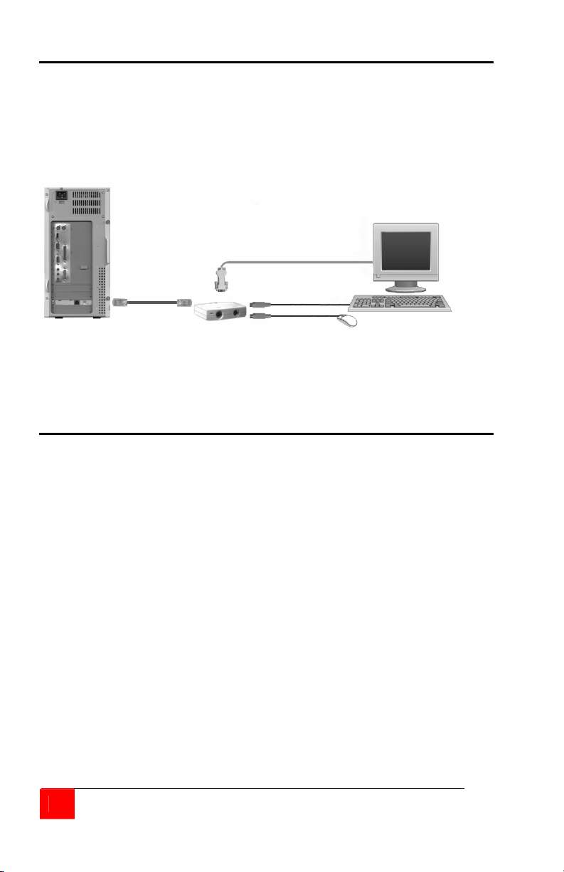
Installing the Remote user module
(NOTE: Power to the computer should be off)
Connect the remote keyboard, monitor, and mouse to the
corresponding connectors on the remote user module. The local
computer’s keyboard, monitor, mouse, and other cable connections
such as a printer, scanner, or USB cables should already be connected
to the corresponding ports on the computer.
Remote KVM Station
Figure 3. Remote user module
Connect the CAT5 cable from the Remote user module’s RJ45
connector to the RJ45 connector on the MultiStation PC’s PCI card.
Applying power
Turn on both the local computer’s monitor and the remote video
monitor and turn on the shared computer. Windows will automatically
recognize the MultiStation PC PCI card as new hardware and will
prompt you to install the appropriate driver. Continue installing the
drivers and after they are installed, re-start the computer when the restart computer prompt displays. This will load the MultiStation PC’s
driver.
8
MULTISTATION PC INSTALLATION AND OPERATIONS MANUAL
Page 13
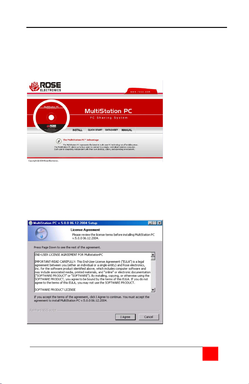
Installing the software
To install the MultiStation PC software, make sure all connections are
secure and no applications are running. Login to Windows XP or 2000
with an account that has administrator privileges. Close any
applications that might be running and insert the MultiStation PC CD. If
the installation procedure does not start automatically, run the
“Index.htm” program from the CD.
From the "Index.htm" display, you can install the software, view the
Quick Start Guide, the product datasheet, and this manual. Click on
INSTALL and the Installation Wizard will start. This software is
copyrighted and you must agree to the license agreement to install and
use this software. Read the license agreement as shown in Figure 4.
If you agree click on the “I agree" button, if not, click "Cancel".
Figure 4. Software license agreement
MULTISTATION PC INSTALLATION AND OPERATIONS MANUAL
9
Page 14
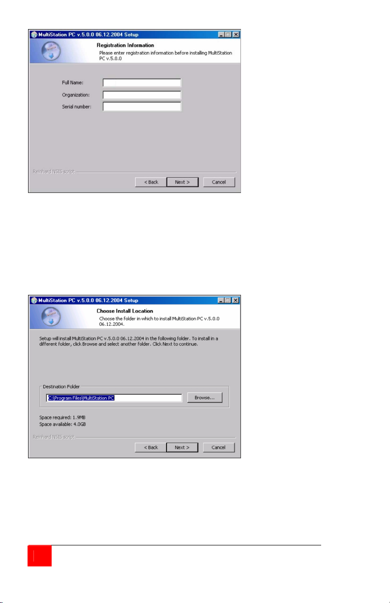
Figure 5. User information
Next, enter the requested User information as shown in Figure 5. Enter
the user information and serial number.
(Note: serial # is located on the installation CD)
When all information has been entered, click "Next".
Figure 6. Destination folder
You can install the MultiStation PC software in the default folder name
“C:\Program Files\MultistationPC\” or change it to a folder name of your
choosing by clicking on the “Browse” button.
(Figure 6)
10
MULTISTATION PC INSTALLATION AND OPERATIONS MANUAL
Page 15
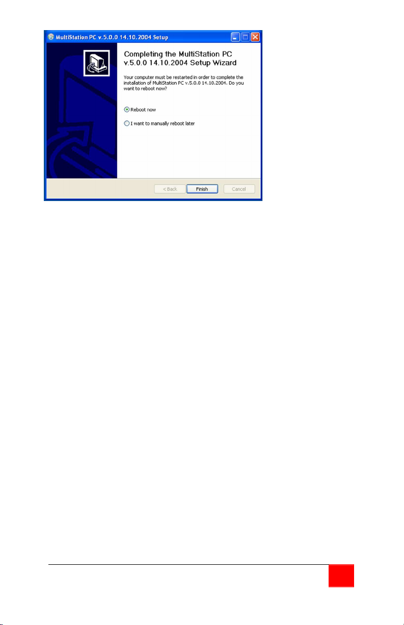
Figure 7. Installation successful
When the installation is complete, the final “Finish” screen will display.
(Figure 7). Click on the “Finish” button and restart the computer to
initialize and load the MultiStation PC software.
MULTISTATION PC INSTALLATION AND OPERATIONS MANUAL
11
Page 16
OPERATION
User Operation
When the shared computer is first booted, the boot-up sequence can
be seen on the monitor connected to the computer. The monitor
connected to the remote user module will remain blank until the
computer fully boots up and the login screen displays. After the
computer fully boots up, the monitor connected to the user module will
change from a blank screen to a blue screen and then to its login
screen. If the monitor remains blank or the boot-up sequence is visible
only on the monitor connected to the remote user module, refer to
troubleshooting section to correct the problem. Due to the many
differences in motherboards, Bios, and system configurations, some
configuration of the MultiStation PC’s PCI card or the system BIOS may
be needed to correct the video problem.
The MultiStation PC, once installed and configured if needed, allows
two users to independently use a single computer. Each user can login
to Windows XP or 2000 with their custom desktop, screen saver, and
Icons. They can run the same application or a different one
simultaneously with no apparent performance degradation.
With the computer connected to a network, each user can connect to
the network using a common network card and access network servers
and printers. Each user can connect to the Internet using a common
modem, phone or DSL line and one internet connection.
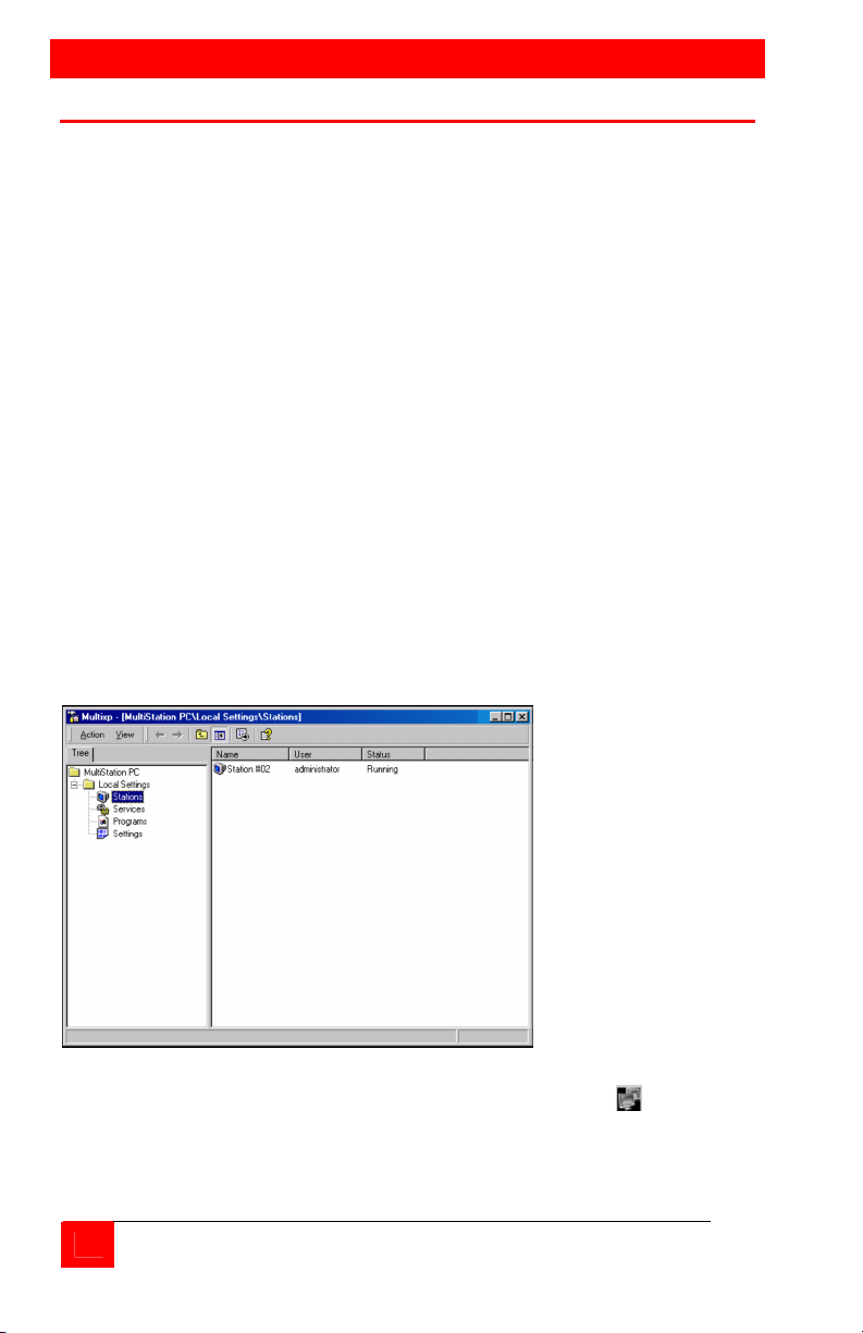
Figure 8. Console window
The MultiStation PC installation will place a Console Icon
running task toolbar. Double click on this Icon to bring up the
MultiStation PC settings (Figure 8 ).
12
MULTISTATION PC INSTALLATION AND OPERATIONS MANUAL
on the
Page 17
OPERATION
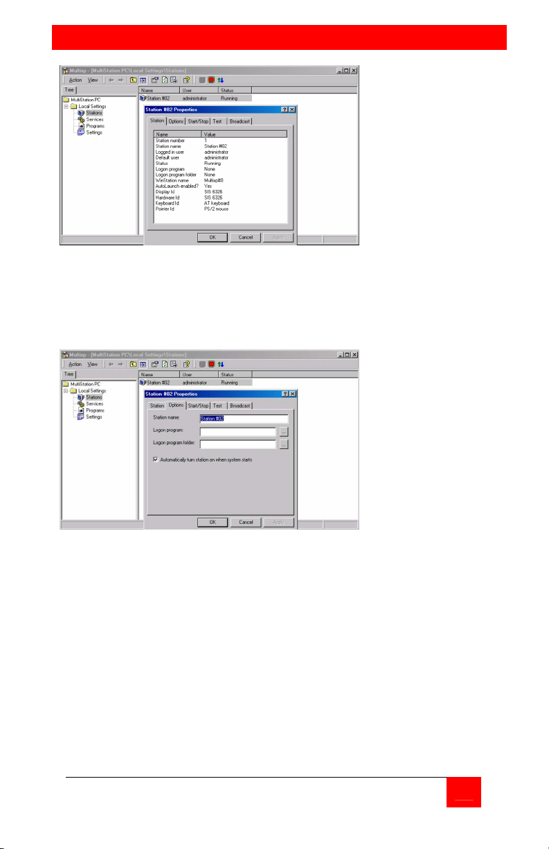
Figure 9. Station Properties
Under “Local settings”, select “Stations” and double clicking on the
station name to display the stations properties (Figure 9).
The “Station” tab displays information about the selected station.
Figure 10. Station options
The ‘Option” tab (Figure 10) allows you to name the station, assign a
Logon program, logon program folder, and automatically turn the
station on when the system starts.
MULTISTATION PC INSTALLATION AND OPERATIONS MANUAL
13
Page 18
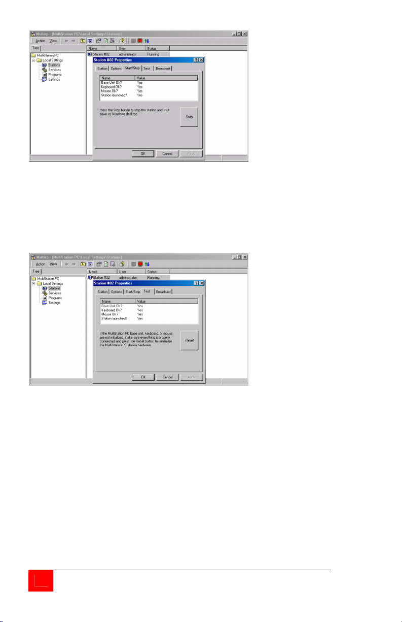
Figure 11. Start/Stop window
The “Start/Stop” tab displays the station’s status and allows you to stop
the station and shut down its windows desktop (Figure 11).
Pressing the “Stop” button will stop the station. If the “Automatically
turn station on when system starts” check box is not checked (refer to
Figure 10), this button will display “Start” so you can start this station.
Figure 12. Test screen
The “Test” tab (Figure 12) verifies that the base unit, keyboard, and
mouse are initialized and the station’s launch status. If any item is not
initialized on start-up, the value for that item will be “No”. Check the
item whose value is “No” and click on the “Reset” button. This will
reinitialize the user module, keyboard, and mouse. The value should
change from “No” to “Yes” for that item.
14
MULTISTATION PC INSTALLATION AND OPERATIONS MANUAL
Page 19
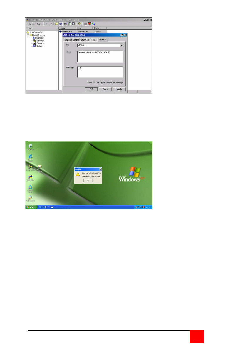
Figure 13. Broadcast message screen
The “Broadcast” tab (Figure 13) is a feature that will broadcast a
message to the other station. Type in your message in the message
box and click “OK”. The text message will display on the other station
in a pop-up message box (Figure 14).
Figure 14. Message box
MULTISTATION PC INSTALLATION AND OPERATIONS MANUAL
15
Page 20

SERVICE and SUPPORT
Service Information
Maintenance and Repair
This Unit does not contain any internal user-serviceable parts. In the
event a Unit needs repair or maintenance, you must first obtain a
Return Authorization (RA) number from Rose Electronics or an
authorized repair center. This Return Authorization number must
appear on the outside of the shipping container.
See Limited Warranty for more information.
When returning a Unit, it should be double-packed in the original
container or equivalent, insured and shipped to:
Rose Electronics
Attn: RA__________
10707 Stancliff Road
Houston, Texas 77099 USA
Technical Support
If you are experiencing problems, or need assistance in setting up,
configuring or operating your MultiStation PC, consult the appropriate
sections of this manual. If, however, you require additional information
or assistance, please contact the Rose Electronics Technical Support
Department at:
Technical Support hours are from: 8:00 am to 6:00 pm CST (USA),
Monday through Friday.
Please report any malfunctions in the operation of this Unit or any
discrepancies in this manual to the Rose Electronics Technical Support
Department.
16
MULTISTATION PC INSTALLATION AND OPERATIONS MANUAL
Page 21

SAFETY
Safety
The MultiStation PC has been tested for conformance to safety
regulations and requirements, and has been certified for international
use. Like all electronic equipment, the MultiStation PC should be used
with care. To protect yourself from possible injury and to minimize the
risk of damage to the Unit, read and follow these safety instructions.
Follow all instructions and warnings marked on this Unit.
Except where explained in this manual, do not attempt to service
this Unit yourself.
Do not use this Unit near water.
Assure that the placement of this Unit is on a stable surface.
Provide proper ventilation and air circulation.
Keep connection cables clear of obstructions that might cause
damage to them.
Use only power cords, power adapter and connection cables
designed for this Unit.
Keep objects that might damage this Unit and liquids that may spill,
clear from this Unit. Liquids and foreign objects might come in
contact with voltage points that could create a risk of fire or
electrical shock.
Do not use liquid or aerosol cleaners to clean this Unit. Always
unplug this Unit from its electrical outlet before cleaning.
Unplug this Unit refer servicing to a qualified service center if any of
the following conditions occur:
The connection cables are damaged or frayed.
The Unit has been exposed to any liquids.
The Unit does not operate normally when all operating
instructions have been followed.
The Unit has been dropped or the case has been damaged.
The Unit exhibits a distinct change in performance, indicating a
need for service.
MULTISTATION PC INSTALLATION AND OPERATIONS MANUAL
17
Page 22

Safety and EMC Regulatory Statements
Safety information
Documentation reference symbol. If the product is marked
with this symbol, refer to the product
documentation to get more information about the product.
WARNING
CAUTION A CAUTION in the manual denotes a hazard that can
Do not proceed beyond a WARNING or CAUTION notice until you
have understood the hazardous conditions and have taken appropriate
steps.
Grounding
These are Safety Class I products and have protective earthing
terminals. There must be an un-interruptible safety earth ground from
the main power source to the product’s input wiring terminals, power
cord, or supplied power cord set. Whenever it is likely that the
protection has been impaired, disconnect the power cord until the
ground has been restored.
Servicing
There are no user-serviceable parts inside these products. Only
service-trained personnel must perform any servicing, maintenance, or
repair.
The user may adjust only items mentioned in this manual.
A WARNING in the manual denotes a hazard that can
cause injury or death.
damage equipment.
18
MULTISTATION PC INSTALLATION AND OPERATIONS MANUAL
Page 23
TROUBLESHOOTING
Keyboard or mouse on remote user module does not work.
Cable is loose; re-seat keyboard or mouse cable at the CPU and
the remote user module and reset the keyboard and mouse (Refer
to Figure 12)
Keyboard and mouse cables reversed.
Boot-up sequence appears on the Remote user module monitor
only
The system BIOS is detecting the MultiStation PC graphic adapter
as the main display adapter. To correct this problem there are two
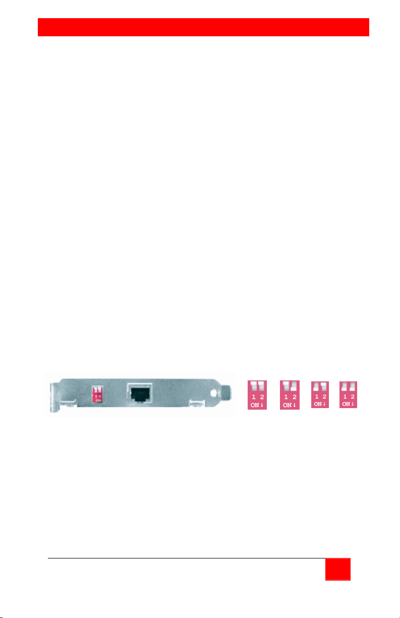
options, either the dipswitches located on the MultiStation PC’s PCI
card need to be changed or the BIOS/CMOS settings need to be
changed.
OPTION 1 – Change dipswitch settings
First verify that the two dipswitches located on the MultiStation PC’s
PCI card are both in the “OFF” position. (Refer to Figure 1) If the
dipswitches are not in the “OFF” position, shut down the computer,
set both switches to “OFF” and restart the computer. If the boot-up
sequence displays on the monitor connected directly to the PC,
proceed with your installation. If not:
Repeat the process of powering down the computer, changing the
dipswitch settings and restarting the computer for each of the
settings until one of the settings resolves the problem. Settings are
“ON”, “OFF” / “OFF”, “ON” / “ON”, “ON”. If this does not correct the
problem set the dipswitches back to “OFF”, “OFF” and try Option 2A
and/or Option 2B.
OFF/OFF
OFF/ON ON/OFF ON/ON
(Default)
OPTION 2 – BIOS/CMOS settings for AGP video adapter
If the host display is AGP, verify that the BIOS setup shows the
AGP adapter as the host adapter
Following are several examples of BIOS setups for different PC’s.
1. Boot your system and enter the BIOS setup. Select “Integrated
Peripherals” and press enter. Verify that the setting for “Init
Display First” is correct. If the display adapter is AGP, this item
should show “AGP”.
MULTISTATION PC INSTALLATION AND OPERATIONS MANUAL
19
Page 24

2. Select “BIOS Features Setup”, enter “VGA Boot from”, and select
the option “AGP”
3. Select “Integrated Peripherals” and press enter. Select “Init
Display First”, then select “Enabled”.
4. Select “PNP, PCI & ON-BOARD I/O” and then select the “Init
Display First” option.
OPTION 2B – PCI video adapter
If your main computer uses a PCI video adapter and the video is only
displaying on the remote user module’s monitor, power down your
computer and remove the MultiStation PC’s PCI card and move your
PCI video card to the slot that was occupied by the MultiStation PC’s
PCI card. Do not install the MultiStation PC’s PCI card at this time. Reboot your system and Windows XP will recognize the new hardware
and install it. Re-install the MultiStation PC’s PCI card in the slot that
was previously occupied by the PCI video adapter and reboot the
system. The boot-up sequence should now appear on the video
monitor connected to the PC and not on the monitor connected to the
remove user module.
Installation of software causes conflicts with my resident
programs
If you experience installation conflicts with startup or resident
applications, it would be advisable to un-install the MultiStation PC
software, reboot, then disable these applications, reboot, and reinstall
the MultiStation PC Software. Once your reinstall the MultiStation PC
software and reboot your PC, enable the startup or resident
applications you disabled and reboot again.
NOTE:
Consult your Operating systems manual or vendor for instruction on
disabling/enabling your startup and resident programs applications.
"Blue Screen" Page Fault Error Message Received after software
install
When the installation is completed, you will be prompted to re-boot
your system. If you receive a blue screen "Page Fault Error Message"
during the re-boot process, please call Rose Electronics Tech Support.
It may be determined that your system board is not compatible with the
MultiStation PC software. This may be correctable with a firmware
change.
20
MULTISTATION PC INSTALLATION AND OPERATIONS MANUAL
Page 25
APPENDICES
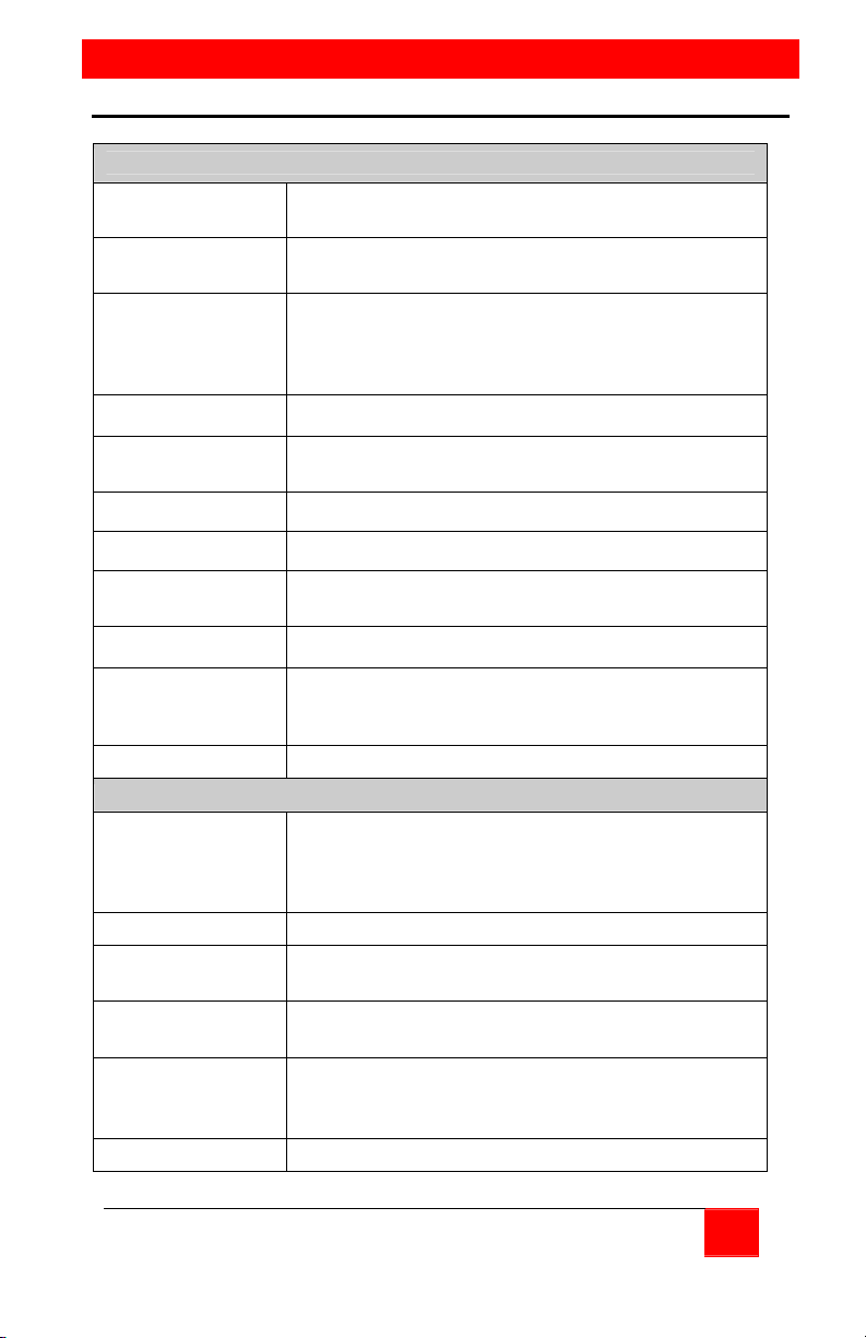
Appendix A. General specifications
MultiStation PC PCI card
Bus Interface
Video Chip Trident 3D Image T9750 Graphics chip (2D/3D
4 MB of SGRAM Supports 1280 x 1024 x 16bit High Color at 60 Hz
Data Transfer Rate Up to 132MB/sec
PCI bus V2.1: 5V, 32bit, 33MHz
graphics accelerator chip)
Supports 1024 x 768 x 32bit True Color at 75Hz
Supports 800 x 600 x 32bit True Color at 75Hz
Supports 640 x 480 x 32bit True Color at 75Hz
Cable Interface
Cable CAT-5 STP (Shielded Twisted Pairs) cable
Distance 50 ft. (15.24m) maximum with optional cable
Dimensions /
weight
Power 7W (1.4A, 5V – PCI card / remote user module)
DIP Switch
Agency Approval USA: FCC - Class B - Europe: CE
MultiStation PC remote user module
Connectors Video – DB15F
Indicators LED for system status / Buzzer for error detection
Dimensions /
weight
Power Remote user module - 5W (From PCI card)
Environmental Operating temp. 34° to 104°F (0° to 40° C)
Approvals FCC Class B, CE
RJ45 jack (with standard Ethernet pin-out for cable
connecting to Remote user module)
6.5" x 4" (16.5cm x 10.1cm) / 3 oz. (0.085 kg)
1 x 4 switch DIP switch bank to accommodate
different motherboard initialization event
counts.(0,4,8,64 counts)
Keyboard – PS/2 (MiniDin6F)
Mouse – PS/2 (MiniDin6F)
Communication – RJ45
2.25" x 3.3" x .75" / 3 oz
5.7 x 8.5 x 1.9cm / 0.085kg
Max power to keyboard – 1W (0.1A, 5V)
Storage temp. -40°F to 140°F (-40° to 60° C)
Humidity -
20% to 90% non-condensing
MULTISTATION PC INSTALLATION AND OPERATIONS MANUAL
21
Page 26

Appendix B. Parts and cables
Part Number Description
KVM-PC42M MultiStation PC PCI card /Module
CAB-08STP015 CAT5 cable
22
MULTISTATION PC INSTALLATION AND OPERATIONS MANUAL
Page 27

Page 28

10707 Stancliff Road Phone: (281) 933-7673
Houston, Texas 77099 WWW.ROSE.COM
 Loading...