

Page 1
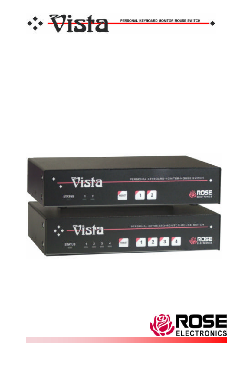
VISTA KVM-SERIES
INSTALLATION AND OPERATIONS
MANUAL
10707 Stancliff Road Phone: (281) 933-7673
Houston, Texas 77099 WWW.ROSE.COM
Page 2

LIMITED WARRANTY
Rose Electronics warrants the Vista™ to be in good working order for one year from the date of purchase
from Rose Electronics or an authorized dealer. Should this product fail to be in good working order at any
time during this one-year warranty period, Rose Electronics will, at its option, repair or replace the Unit as
set forth below. Repair parts and replacement units will be either reconditioned or new. All replaced parts
become the property of Rose Electronics. This limited warranty is valid only if repairs are performed by
Rose Electronics or a Rose qualified service technician. This limited warranty is void if repairs are not
performed by Rose Electronics or a Rose qualified service technician. This limited warranty does not
include service to repair damage to the Unit resulting from accident, disaster, abuse, or unauthorized
modification of the Unit, including static discharge and power surges.
Limited Warranty service may be obtained by delivering this unit during the one-year warranty
period to Rose Electronics or an authorized repair center providing a proof of purchase date. If this
Unit is delivered by mail, you agree to insure the Unit or assume the risk of loss or damage in
transit, to prepay shipping charges to the warranty service location, and to use the original shipping
container or its equivalent. You must call for a return authorization number first. Under no
circumstances will a unit be accepted without a return authorization number. Contact an authorized
repair center or Rose Electronics for further information.
ALL EXPRESS AND IMPLIED WARRANTIES FOR THIS PRODUCT INCLUDING THE
WARRANTIES OF MERCHANTABILITY AND FITNESS FOR A PARTICULAR PURPOSE, ARE
LIMITED IN DURATION TO A PERIOD OF ONE YEAR FROM THE DATE OF PURCHASE, AND
NO WARRANTIES, WHETHER EXPRESS OR IMPLIED, WILL APPLY AFTER THIS PERIOD.
SOME STATES DO NOT ALLOW LIMITATIONS ON HOW LONG AN IMPLIED WARRANTY
LASTS, SO THE ABOVE LIMITATION MAY NOT APPLY TO YOU.
IF THIS PRODUCT IS NOT IN GOOD WORKING ORDER AS WARRANTIED ABOVE, YOUR
SOLE REMEDY SHALL BE REPLACEMENT OR REPAIR AS PROVIDED ABOVE. IN NO EVENT
WILL ROSE ELECTRONICS BE LIABLE TO YOU FOR ANY DAMAGES INCLUDING ANY LOST
PROFITS, LOST SAVINGS OR OTHER INCIDENTAL OR CONSEQUENTIAL DAMAGES
ARISING OUT OF THE USE OF OR THE INABILITY TO USE SUCH PRODUCT, EVEN IF ROSE
ELECTRONICS OR AN AUTHORIZED DEALER HAS BEEN ADVISED OF THE POSSIBILITY OF
SUCH DAMAGES, OR FOR ANY CLAIM BY ANY OTHER PARTY.
SOME STATES DO NOT ALLOW THE EXCLUSION OR LIMITATION OF INCIDENTAL OR
CONSEQUENTIAL DAMAGES FOR CONSUMER PRODUCTS, SO THE ABOVE MAY NOT
APPLY TO YOU. THIS WARRANTY GIVES YOU SPECIFIC LEGAL RIGHTS AND YOU MAY
ALSO HAVE OTHER RIGHTS, WHICH MAY VARY FROM STATE TO STATE.
NOTE: This equipment has been tested and found to comply with the limits for a Class A digital
device, pursuant to Part 15 of the FCC Rules. These limits are designed to provide reasonable
protection against harmful interference when the equipment is operated in a commercial
environment. This equipment generates, uses, and can radiate radio frequency energy and, if not
installed and used in accordance with the instruction manual, may cause harmful interference to
radio communications. Operation of this equipment in a residential area is likely to cause harmful
interference in which case the user will be required to correct the interference at his own expense.
IBM, AT, and PS/2 are trademarks of International Business Machines Corp. Microsoft and
Microsoft Windows are registered trademarks of Microsoft Corp. Any other trademarks mentioned
in this manual are acknowledged to be the property of the trademark owner.
Copyright Rose Electronics 1990-2001. All rights reserved.
No part of this manual may be reproduced, stored in a retrieval system, or
transcribed in any form or any means, electronic or mechanical, including
photocopying and recording, without the prior written permission of Rose
Electronics.
Rose Electronics Part # MAN-V8
Printed In the United States of America - Revision 2.0
Page 3

FCC/IC STATEMENTS, EU DECLARATION OF CONFORMITY
FEDERAL COMMUNICATIONS COMMISSION AND INDUSTRY CANADA
RADIO-FREQUENCY INTERFERENCE STATEMENTS
This equipment generates, uses and can radiate radio frequency energy
and if not installed and used properly, that is in strict accordance with the
manufacturer’s instructions may cause interference to radio
communication. It has been tested and found to comply with the limits for
a Class B digital device in accordance with the specifications of Part 15 of
FCC rules, which are designed to provide reasonable protection against
such interference when the equipment is operated in a commercial
environment. Operation of this equipment in a residential area is likely to
cause interference, in which case the user at his own expense will be
required to take whatever measures may be necessary to correct the
interference.
Changes or modifications not expressly approved by the party responsible
for compliance could void the user’s authority to operate the equipment.
This digital apparatus does not exceed the Class A limits for radio noise
emission from digital apparatus set out in the Radio Interference
Regulation of Industry Canada.
Le présent appareil numérique n’émet pas de bruits radioélectriques
dépassant les limites applicables aux appareils numériques de la classe A
prescrites dans le Règlement sur le brouillage radioélectrique publié par
Industrie Canada.
EUROPEAN UNION DECLARATION OF CONFORMITY
This equipment complies with the requirements of the European EMC
directive 89/336/EEC in respect of EN55022 (Class B), EN50082-1 and
EN60555-2 standards and the Low Voltage Directive.
Page 4

TABLE OF CONTENTS
Contents
Disclaimer................................................................................................1
Introduction..............................................................................................1
Product Registration................................................................................2
Features..................................................................................................2
Compatibility.......................................................................................3
System overview......................................................................................4
KVM station........................................................................................4
CPU connections................................................................................4
Rose Electronics web site...................................................................5
Vista KVM-Series models.........................................................................6
Installation...............................................................................................9
Step 1 - Connecting the KVM station...................................................9
Step 2 - Connect the CPUs ...............................................................10
Step 3 - Applying power....................................................................10
Step 4 – Verify keyboard, mouse and CPU operation........................10
Operating instructions............................................................................12
Keyboard command...............................................................................12
Keyboard command description........................................................14
KVM Flash Upgrade Utility.....................................................................17
TroubleShooting ....................................................................................20
Maintenance and repair.........................................................................22
Technical support...................................................................................22
Safety....................................................................................................23
Tables
Table 1. Compatibility...............................................................................3
Table 2. Front panel description...............................................................6
Table 3. Vista 2UPH/4UPH description....................................................7
Table 4. Vista 2PCA/4PCA description.....................................................8
Table 5. Keyboard commands................................................................13
Figures
Figure 1. Typical installation.....................................................................5
Figure 2. Vista 2 port................................................................................6
Figure 3. Vista 4 port................................................................................6
Figure 4. Vista to KVM station..................................................................9
Figure 5. Vista to CPU's.........................................................................10
Figure 6. Vista to CrystalView................................................................11
Appendix
Appendix A. Initial factory settings..........................................................26
Appendix B. Parts and cables ................................................................27
Appendix C. General specifications........................................................28
Appendix D. Rack mount instructions.....................................................29
Appendix E. Rack mount illustration.......................................................29
Appendix F. Typematic rate...................................................................30
Page 5
INTRODUCTION
A Keyboard,
V
ideo monitor and
M
ouse are referred to
Disclaimer
While every precaution has been taken in the preparation of this manual,
the manufacturer assumes no responsibility for errors or omissions.
Neither does the manufacturer assume any liability for damages resulting
from the use of the information contained herein. The manufacturer
reserves the right to change the specifications, functions, or circuitry of the
product without notice.
The manufacturer cannot accept liability for damages due to misuse of the
product or other circumstances outside the manufacturer’s control. The
manufacturer will not be responsible for any loss, damage, or injury arising
directly or indirectly from the use of this product.
Introduction
Thank you for choosing the Rose Electronics Vista Personal KVM
switch. The Vista switch is the result of Rose Electronics commitment to
providing state-of-the-art switching solutions for today’s demanding work
place. The Vista switch has proven to be a valuable investment for users
that have a need to access multiple CPUs from a single KVM station.
throughout this manual as a KVM station.
Please refer to the safety section first before proceeding with any
installation or configuration of the Vista switch.
The Vista KVM-series switch is available in four models. The 2-port and 4port models are available with DB25 connectors or PC connectors.
For the Vista models with DB25 connectors, it is recommended that Rose
Electronics cable part number CAB-ZX0606Cnnn or CAB-CX0606Cnnn
(DB25 to HD15/PS2/PS2) CPU Cable be used.
For the models with PC connectors, it is recommended that Rose
Electronics cable part number CAB-CXV66MMnnn or CAB-ZX66MMnnn
(VGA/PS/2 keyboard/PS/2 mouse cable) be used.
The Vista switch can simplify your job by helping you organize your
multiple computer applications. Because the Vista switch lets you use a
single keyboard, video monitor, and mouse to access several computers,
you can significantly reduce your equipment overhead and end keyboard
and monitor clutter.
Vista KVM-Series Installation and Operations Manual
1
Page 6

Product Registration
Take advantage of the following when you register your Rose Electronics
products online at www.rose.com/htm/warranty.htm:
§ Rose Standard Warranty Plus...
§ Free Lifetime Firmware Updates
§ Free Lifetime Technical Support
§ 30 Day Money Back Guarantee
§ Priority “First-in-Line” Status for Tech Support
Features
§ Available with DB25 or PC (keyboard, video monitor, mouse) CPU
connectors
§ Access up to 2 or 4 computers from one KVM station
§ Select a computer from the front panel or simple keyboard commands
§ Power is obtained from the attached CPUs, eliminating the need for an
external power source. An external power adapter can be used if using
a wireless keyboard and mouse
§ Front panel LEDs show status and selected CPU port
§ Keyboard, video monitor, and mouse plug directly into the unit
§ Scan mode automatically sequences through CPUs at adjustable rate
§ Non-volatile memory stores configuration settings
§ Full emulation of keyboard and mouse, allowing computers to be
booted at any time
§ Supports PS/2 mouse, wheel mouse, and serial mouse
§ Keyboard Num Lock, Caps Lock, and Scroll Lock states automatically
saved and restored when switching among CPUs
§ Keyboard mode is automatically detected for simultaneous support of
PCs, Unix computers, and IBM mode 1 computers
§ Reset button reinitializes all ports
§ Keyboard lockout function <Ctrl L>
§ Low cost and easy to use
§ Heavy-duty steel, fully shielded chassis
§ Rackmount option for 19", 23", or 24" racks (1 rack unit high, 1.75”)
§ Saves space, reduces equipment and power costs, and eliminates
clutter
§ Unlimited technical support
§ Made in USA
2
Vista KVM-Series Installation and Operations Manual
Page 7
Compatibility
CPUs
Computers Industry standard PCs, Unix computers such as
RS-6000, HP 9000, SGI, DEC Alpha, MAC and others
Monitors SVGA
Keyboards PC PS/2, AT, PC and Apple USB
Mouse Standard PS/2 Mouse (2 or 3 button)
PC and Apple USB
Serial Mouse (2 or 3 button)
KVM Station
Monitors SVGA
Keyboards US, Korean, Japanese, keyboards with or without
Windows keys (101, 102, 104, 105, 106, 109 keys)
(Some older XT/AT auto-sensing keyboards may not
be compatible)
Mouse Standard PS/2 Mouse (2 or 3 button)
PS/2 Wheel Mouse (2 button + wheel)
PC and Apple USB
Serial Mouse (2 or 3 button)
Table 1. Compatibility
Package contents
The package contents consist of the following:
§ The Vista Unit
§ Power adapter (Optional)
§ Installation and operations manual
CPU cables are usually ordered separately. If the package contents are
not correct, contact Rose Electronics or your reseller so the problem can
be quickly resolved.
Vista KVM-Series Installation and Operations Manual
3
Page 8

OVERVIEW
System overview
The Vista KVM-series switch is designed to provide seamless, trouble-free
switching from a single KVM station to any connected CPU. You can
switch to the connected computers by simple keyboard commands or
using the front panel buttons.
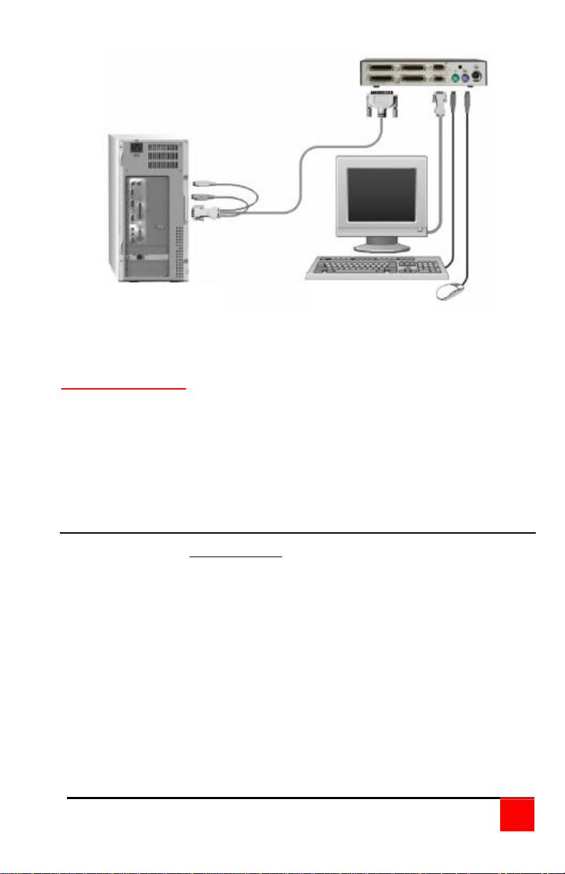
Figure 1 shows a typical configuration using the Vista 4 port switch with
DB25 connectors. Up to 4 CPUs can be connected to the Vista 4 port
switch and accessed from a single KVM station.
KVM station
A KVM station, consisting of a keyboard, video monitor and mouse,
connects directly to the Vista switches’ KVM connectors. The KVM station
can switch its keyboard, video monitor and mouse to any of the connected
CPUs and fully control that CPU if authorized. Files and folders can be
managed, applications can be executed, upgrades can be performed and
general maintenance done from the KVM station.
The keyboard, video monitor and mouse used for the KVM station should
be compatible with all of the CPU that will be connected. The KVM stations
mouse must be a PS/2 mouse. The Vista switch will translate PS/2 mouse
movements and present it in serial form to computers that use a serial
mouse The KVM connectors on the Vista switch are HD15F for the video
monitor and MiniDin-6F for the keyboard and mouse.
CPU connections
The CPU connectors on the Vista switch depend on the model ordered.
The “U” model connectors are DB25F for each CPU. The “PC” model
connectors are HD15F (video) and MiniDin-6F (keyboard and mouse) for
each CPU. Attached CPUs that use a serial mouse, use adapter ACCKVM6F9F to connect to the CPUs serial port (do not substitute).
4
Vista KVM-Series Installation and Operations Manual
Page 9
UP TO 4 CPUs
KVM STATION
Figure 1. Typical installation
Power connectors
The optional power connector on the Vista switch is for a supplemental
power adapter. Supplemental power may be needed if the cable length
from the computers to the Vista switch is long or you are using a wireless
keyboard and mouse. If your system only switches video, the power
adapter must be used. (Part # ACC-KBPWR-5)
Rose Electronics web site
Visit our web site at www.rose.com for additional information on the Vista
and other products offered by Rose Electronics that are designed for
server room and data center applications, classroom environments and
many other switching applications.
Vista KVM-Series Installation and Operations Manual
5
Page 10
MODELS
Vista KVM-Series models
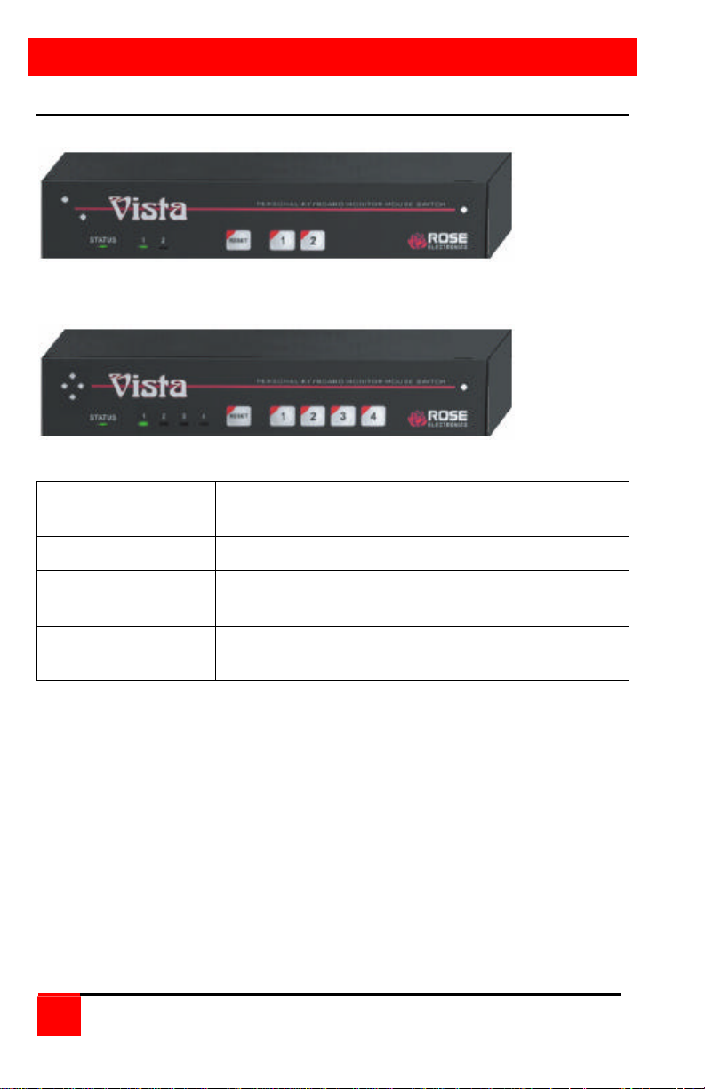
Figure 2. Vista 2 port
Figure 3. Vista 4 port
Status LED Lit when selected CPU has power. Flashes when
Keyboard and mouse data is sent to the unit
Select LEDs Indicates which computer is selected
Reset button Resets the unit and initializes the keyboard and
mouse
CPU Select buttons
(1 – 2 or 1 – 4)
Selects the computer to be accessed
Table 2. Front panel description
6
Vista KVM-Series Installation and Operations Manual
Page 11
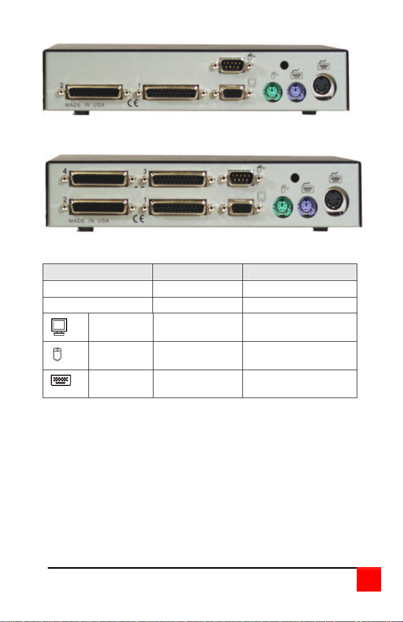
KVM-2UPH rear connectors
KVM-4UPH rear connectors
Label Connector type Description
(2UPH) 1,2 DB25F Computer connectors
(4UPH) 1,2,3,4 DB25F Computer connectors
Monitor HD15F KVM monitor
Mouse MiniDin-6F or
Keyboard MiniDin-6F or
DB9F
Din5F
connector
KVM PS/2 or Serial
mouse connector*
KVM PS/2 or A/T
keyboard connector
Table 3. Vista 2UPH/4UPH description
* KVM-2/4UPMH models do not have a serial mouse connector
Vista KVM-Series Installation and Operations Manual
7
Page 12
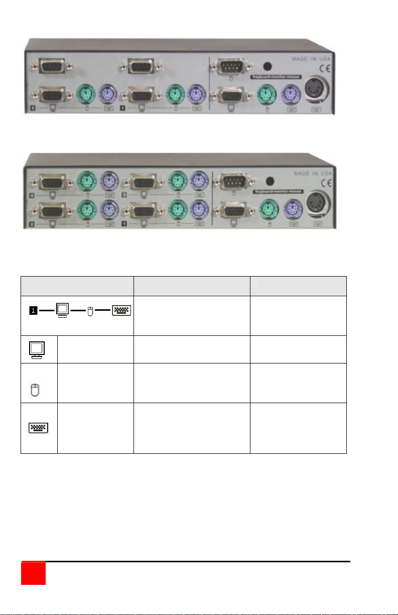
KVM-2PCA rear connectors
KVM-4PCA rear connectors
Label Connector Type Description
Keyboard (MiniDin-6F)
Mouse (MiniDin-6F)
Video (HD15F)
Monitor HD15F
Mouse
Keyboard
MiniDin-6F or
DB9F
MiniDin-6F or
Din5F
CPU connectors
1-2 on 2PC model
1-4 on 4PC model
KVM monitor
connector
KVM PS/2 or
Serial mouse
connector*
KVM PS/2 or A/T
keyboard
connector
Table 4. Vista 2PCA/4PCA description
* KVM-2/4UPMH models do not have a serial mouse connector
8
Vista KVM-Series Installation and Operations Manual
Page 13
INSTALLATION
Installation
Installation of the Vista switch consists of the following steps:
1. Connect the KVM station to the Vista switch
2. Connect the CPUs to the Vista switch
3. Sequentially apply power, boot the CPUs
4. Verify keyboard, mouse and CPU operation
It is recommended that the CPUs be powered off.
Step 1 - Connecting the KVM station
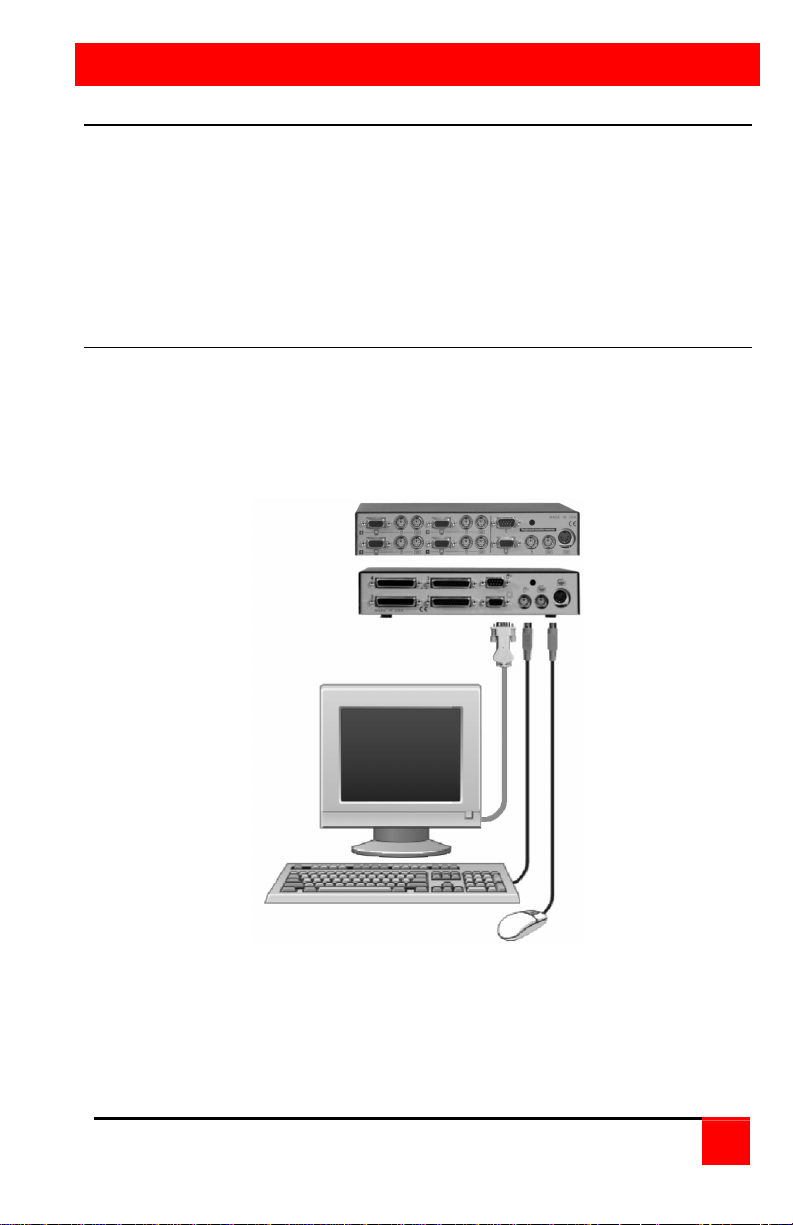
Connect your KVM station’s keyboard, video monitor and mouse cables to
the corresponding Vista switches’ keyboard, video monitor and mouse
connectors as shown in Figure 4.
Figure 4. Vista to KVM station
Vista KVM-Series Installation and Operations Manual
9
Page 14
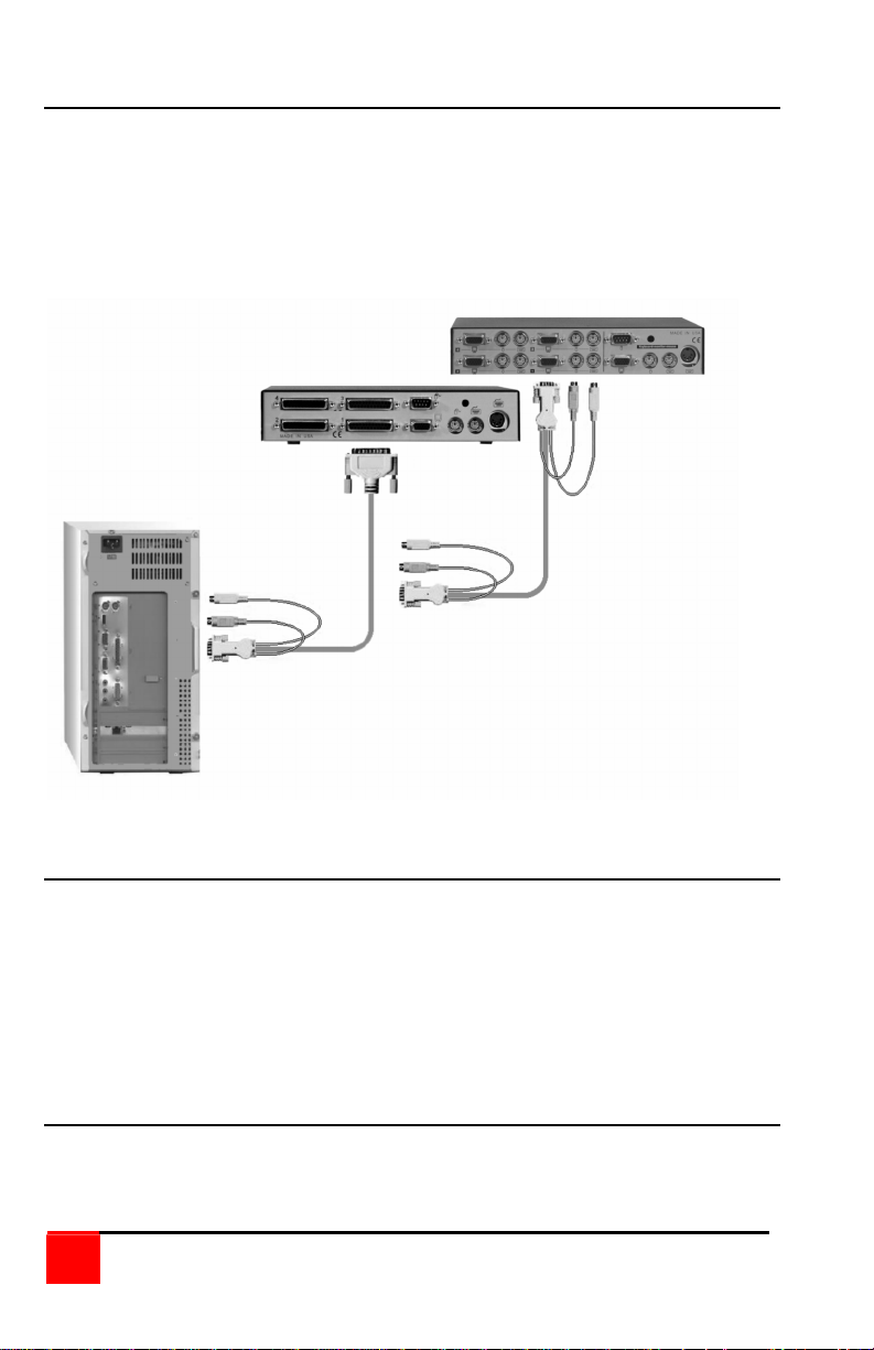
Step 2 - Connect the CPUs
Connect the CPU keyboard, video monitor and mouse ports to the
corresponding Vista switches keyboard, video monitor and mouse ports
using the appropriate CPU cables as shown in Figure 5.
For attached CPUs that use a serial mouse, use adapter ACC-KVM6F9F
to connect to the CPUs serial port (do not substitute).
Figure 5. Vista to CPU's
Step 3 - Applying power
It is recommended that each connected CPU be booted up starting with
the CPU connected to Port #1. Switch the Vista to the CPU port by
pressing the appropriate numbered button on the front panel (1-2 or 1-4).
Boot that CPU. Verify that the mouse and keyboard function properly. If
the keyboard or mouse does not respond, see the troubleshooting section.
Verify that the CPU functions and applications perform properly before
booting up the next CPU. Perform this procedure for all connected CPU.
Step 4 – Verify keyboard, mouse and CPU operation
Verify the keyboard and mouse function properly for each CPU that is
connected to the Vista switch. Refer to the troubleshooting section if
needed.
10
Vista KVM-Series Installation and Operations Manual
Page 15
LOCAL
REMOTE
AWAY
CrystalView
KVM Station
Rack mounting
The Vista switch is designed to mount in a CPU rack or under a desktop.
Rackmount kits are available in three different sizes, 19", 23", and 24".
Each is 1 rack unit high (1.75").
(See Appendix D and Appendix E for rack mounting instructions.)
Your Vista switch is now ready for operation using the initial factory
settings. Pressing the numbered buttons (1-2 or 1-4) on the front panel will
switch to that port. To take full advantage of the Vista features, refer to the
operating instructions for detailed information about each of the Vista
commands. The keyboard commands are summarized in Table 5.
To begin switching immediately from the keyboard, press and release the
left control <Ctrl> key, then type in the computer number (1-2 or 1-4). The
video from the connected computer will display on the KVM’s video
monitor and you will have full control of that computer.
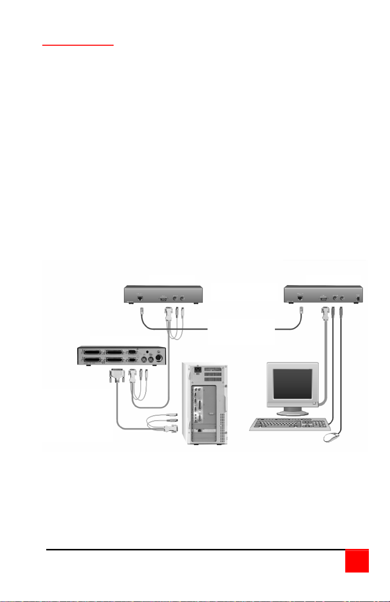
The keyboard, video monitor, and mouse signals can be driven up to
1,000 feet using our CrystalView KVM extenders. This arrangement is
ideal for use in hazardous areas where the computers need to be located
away from the users.
UP TO 4 CPUs CAN
BE ACCESSED
FROM A SINGLE
KVM STATION
FROM UP TO 1,000’
Figure 6. Vista to CrystalView
UP TO 1,000’
CAT-5 CABLE
VISTA SWITCH
Vista KVM-Series Installation and Operations Manual
11
Page 16

OPERATIONS
Operating instructions
The Vista switch is very easy to operate. Computer selection and set-up
functions are entered from the keyboard. You can also select computers
manually from the Vista’s front panel by using buttons 1-2 or buttons 1-4
depending on your model.
Keyboard command
Following is a description of the Vista keyboard command functions.
The <Ctrl> input key sequence is a press and release of the left control
key. Within 2 seconds of pressing and releasing the left <Ctrl> key, enter
the next command.
Command Key Sequence Description
Reset
command
Reset mouse
command
Send null byte <Ctrl> N Used to re-synchronize PS/2
Identify ROM
version
Keep <Ctrl> K Saves current scan state and
Scan time
interval
Mode
command
<Ctrl> R Resets and enables mouse and
keyboard, enables PS/2 mouse
on currently selected port.
<Ctrl> O Sends reset mouse command to
currently selected CPU. Will
recover stuck NT mouse.
mouse.
<Ctrl> I Identifies ROM version, CPU
must be at a command prompt,
word processor, or text editor to
receive value.
custom settings.
<Ctrl> Txx <Enter>
(xx = 1 – 16 sec.)
<Ctrl> M x <Enter>
Where:
x = 1 for mode 1
x = 2 for mode 2
x = 3 for mode 3
Sets the pause time for each
port when scanning.
First select the CPU port to
configure, and then enter the
mode command.
Mode 1, 2, 3 for keyboard:
Mode 7, 8, 9 for mouse
x = 7 for mode 7
x = 8 for mode 8
x = 9 for mode 9
12
Vista KVM-Series Installation and Operations Manual
Page 17

Keyboard commands (continued)
Command Key Sequence Description
Maximum
computers
Typematic
value
Mouse type <Ctrl> Q x <Enter>
<Ctrl> P x <Enter>
(x = 1 – 2 or 1 – 4)
<Ctrl> Ax <Enter>
See Attachment F.
Where:
Limits scanning to maximum
port number
Factory setting = 43
Rate = 10.9 chars/sec
Delay = 500 millisec.
First select the CPU port, and
then enter the type command
x = 0 for PS/2
x = 1 for Serial
x = 2 for Wheel
x = 3 for MAC ADB
Computer
Select
<Ctrl> x
(x = 1, 2 or 3, 4)
Connects your keyboard, video
monitor, and mouse to the
selected computer.
Connect to
next computer
Connect to
previous
<Ctrl> + (Plus) Selects the next sequential
computer.
<Ctrl> - (Minus) Selects the previous sequential
computer.
computer
Computer
<Ctrl> L Disconnects from computer.
disconnect.
Scan (On) <Ctrl> S Turns scan mode on, causing
the Vista to start scanning
sequentially from the current
port through the remaining
ports and start again at Port 1.
Scan (Off) <Ctrl> X Turns scan mode off.
Reset mouse
command
<Ctrl> O Sends reset mouse command
to the currently selected
computer. Will recover stuck
NT mouse
Table 5. Keyboard commands
Vista KVM-Series Installation and Operations Manual
13
Page 18

Follow e
ach set
-
up command with the “Keep” command
to save the changes.
“Keep” command = press and release the left <Ctrl> key,
then the “K” key.
Use only the numeric keys above the keyboard. The keypad will not work.
All keyboard commands must be entered within 2 seconds of pressing and
releasing the left <Ctrl> key.
Keyboard command description
Computer select
To select a computer from your keyboard, press and release the left <Ctrl>
key and then type in the computer number (1-2 or 1-4).
Next computer
To switch to the “Next computer”, press and release the left <Ctrl> key,
then press the plus/equal key.
Previous computer
To switch to the “Previous computer”, press and release the left <Ctrl> key
then press the minus/underscore key.
Scan mode (On)
To enable the “Scan mode”, press and release the left <Ctrl> key, then
type S. The Vista switch will begin scanning sequentially from its current
computer through the remaining computers (as set by the maximum
computers command), and then begin again at computer 1.
Scan mode (Off)
To stop the “Scan mode”, press and release the left <Ctrl> key and then
type “X”. Issuing a computer select command also turns off scanning.
Scan time interval
The “Scan Time interval” command sets the time, in seconds that the Vista
switch will pause at each of the computers when scanning. The default
setting is 5 seconds. To change the Scan Time to another interval press
and release the left <Ctrl> key, type “T” then enter the new scan time
interval (1-16 seconds), and press <Enter>.
14
Vista KVM-Series Installation and Operations Manual
Page 19

Reset
To “Reset” the mouse and keyboard, press and release the left <Ctrl> key,
then type “R”. This command is used to reset the mouse and keyboard on
the currently selected Vista port without removing power from the Vista
switch. This is most useful to reset a PS/2 mouse that has been unplugged
and plugged back in. Upon issuing this command, all keyboard LEDs will
go on and then return to their previous state.
Reset computer mouse type (NT and WIN 2K systems only)
DO NOT issue this command on non-NT or Win 2K based computers.
Press and release the left <Ctrl> key, then type “O”. This command sends
a reset mouse command to the currently selected NT or Win 2K computer.
The command is used to recover a stuck mouse on an NT or Win 2K
system.
Send null byte
Press and release the left <Ctrl> key, then type “N”. This command is
used to re-synchronize an out-of-sync PS/2 mouse. The command may
need to be entered once or twice, depending if the mouse is out-of-sync by
one or two bytes.
Identify ROM version
Press and release the left <Ctrl> key, then type “I”. This command is used
to identify the revision level of the Vista firmware currently installed. Before
entering this command, the selected CPU must be at a command prompt,
word processor, or text editor, so when the Vista switch sends the ROM
revision level the result can be displayed.
Keep command
Press and release the left <Ctrl> key, then type “K”. The Keep command
saves all settings.
Mode command
The Vista switch supports keyboard modes 1, 2 and 3 and mouse modes
7,8, and 9. To issue the “Mode” command, press and release the left
<Ctrl> key, type “M”, then enter the mode number (1,2,3,7,8,9) followed by
<Enter>.
Mode 1 - CPU Keyboard = PC Mode 1 (Some IBM’s & PS/1’s)
Mode 2 - CPU Keyboard = PC Mode 2 (Most PCs)
Mode 3 - CPU Keyboard = PC Mode 3 (Most (RISC) Unix Workstations
Mode 7 - CPU Mouse = 2 Button Serial (Microsoft) (7 Bt)
Mode 8 - CPU Mouse = 2 Button Serial (Not Used) (8 Bt)
Mode 9 - CPU Mouse = 3 Button Serial (Mouse Systems)
Vista KVM-Series Installation and Operations Manual
15
Page 20

Maximum computers
Press and release the left <Ctrl> key, type “P”, enter the total number of
computers, and press <Enter>. This command limits the number of
computers to scan. For example on an four-port unit, if no computers were
connected to ports 3 and 4, setting maximum computers to 2 would
bypass scanning computers 3 and 4.
Typematic command
Initial factory setting = 43. Rate = 10.9 chars/sec, Delay = 500 millisec.
See Attachment F for typematic value calculations.
Mouse type
To issue the “Mouse type” command press and release the left <Ctrl> key,
type “Q”, enter mouse type (0,1,2), and press <Enter>.
Mouse type 0 = PS/2 mouse
Mouse type 1 = Serial mouse
Mouse type 2 = Wheel mouse
Reset to initial factory settings
The settings that have been previously set and saved in non-volatile
memory can be returned to their initial factory settings by holding in
buttons “1" and “2” on the front panel and press and release the ”Reset"
button. At least one CPU must be connected to the unit, so that the unit
can be powered. The activity LED will flash three times to signify that the
non-volatile memory has been returned to the original factory settings.
Only those settings listed in Appendix A are reset, all other settings remain
unchanged from their set values.
16
Vista KVM-Series Installation and Operations Manual
Page 21

FLASH UPGRADE PROCEDURE
KVM Flash Upgrade Utility
Installation of KVM Utility
The installer for the KVM Utility may be distributed in one of two
formats: a ZIP file or an EXE.
If the installer is distributed as a ZIP file, open it in WinZip and unzip
the contents to a known location. The ZIP file contains the EXE
format.
Double-click on the EXE file and follow the on-screen instructions to
install the KVM Utility. Installation is a standard Windows type
installation. After installation, the KVM Utility can be launched from
the Desktop, the Start Menu and/or the Quick Launch bar to the right
of the Start button on the Taskbar.
Hookup of Device
The KVM flash upgrade utility is a universal program used to flash
several models. In order for the KVM Utility to detect the correct
device to flash, it must be connected directly to a PC and the PC must
be connected to port 1 on the switch.
Running the KVM Utility
When the KVM Utility has been successfully installed, it can now be
run. If the device has been hooked up as described above, the KVM
Utility will auto-detect the device when it is launched and display the
connected device. Otherwise, it will display a message that an
incorrect device has been connected.
Once the KVM Utility has detected the device correctly, the device
may be flashed or configured from the File Menu. The following page
summarizes the installation procedure.
More Information
The Quick Start Guide that follows provides a step by step procedure for
installing the firmware upgrade. This upgrade procedure can only be
performed on firmware versions KVM-V5x or greater. Older model chips
are not flash upgradeable. You must upgrade firmware chips on these
models.
Vista KVM-Series Installation and Operations Manual
17
Page 22
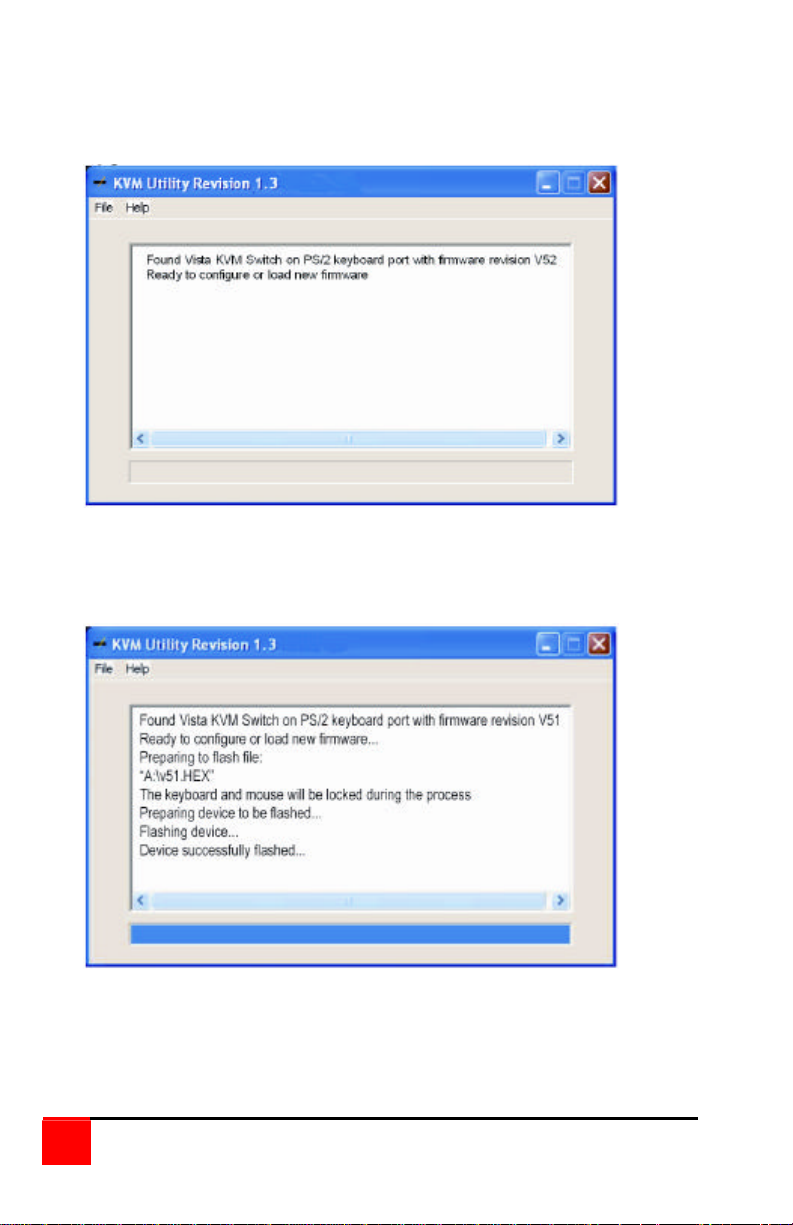
1. Download the flash upgrade firmware and unzip it to an .EXE file
2. Download to a computer connected to port #1.
3. Run the unzipped “EXE” file. Program will auto-detect the unit
4. Click on "File", then "Load New Firmware"
5. Locate the downloaded unzipped file (xxxx.hex) to run
6. The updated firmware file (xxxx.hex) will be installed on the unit
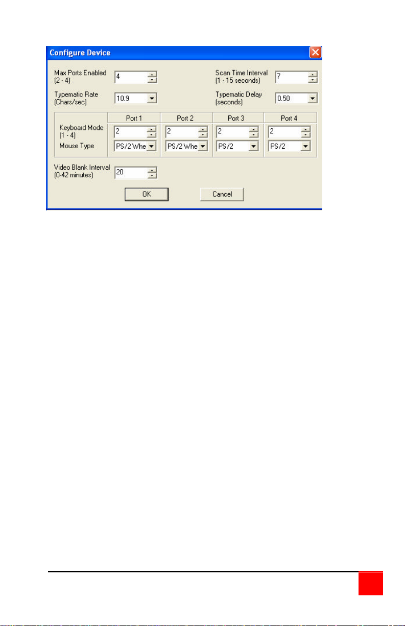
7. The Flash Upgrade utility can also be used to configure the KVM
switch. Click on "File", then "Configure Device". The
configuration screen will display, allowing you to configure the
"MaxPorts", keyboard and mouse type for each port and other
items shown in the below display.
18
Vista KVM-Series Installation and Operations Manual
Page 23
8. When the firmware has been successfully installed the unit is
now operational with the firmware upgrade.
A more comprehensive explanation of the firmware upgrade process
can be viewed by clicking on "Help". The on-line help walks you
through each step in detail
Vista KVM-Series Installation and Operations Manual
19
Page 24

TROUBLESHOOTING
TroubleShooting
CPU does not boot, keyboard or mouse error received
• Cable is loose, reseat cable and hit F1 to continue or reboot
computer.
• Wrong cable plugged in, keyboard and mouse cables reversed.
• Cable is defective; try using a cable from another CPU. If the
problem goes away cable is defective.
• Port on the Vista switch is defective; try using another port. If the
problem goes away port is defective.
• Port on CPU is defective, try plugging in keyboard or mouse directly.
If the problem remains, the CPU port is defective. If the activity LED
is not lit when switched to computer, which is powered on, the fuse
on the computer’s motherboard may be blown.
Mouse driver does not load
• If using a PS/2 type mouse, the CPU must be connected to the Vista
or mouse at boot-up time in order for mouse to be recognized by
CPU. Reboot the computer with the Vista powered on and cable
attached.
• If using a serial type mouse make sure the right COM port is being
used and the syntax of mouse driver is correct.
• Incompatible or old mouse driver being used, update the driver.
• Mouse translation is set incorrectly.
Can’t switch ports from keyboard
• You must press and release the left control key before you press the
key that specifies the port number. You must also use the numeric
keys above the alphabetic keys, not those on the numeric keypad.
Wrong or missing characters from those typed
• The mode of the keyboard does not match that of the CPU. Issue the
mode command, usually 1 for IBM PS/1, 2 for most other PS/2 PCs,
and 3 for Unix computers. The default setting of the Vista is mode 2.
An incorrect mode can confuse the CPU or keyboard and require rebooting the CPU or resetting the keyboard by unplugging and
plugging it back in.
PS/2 mouse gets out of sync
• Cabling was disturbed during mouse movement. Issue the null
command once or twice to re-sync the mouse. Update to the latest
mouse driver.
20
Vista KVM-Series Installation and Operations Manual
Page 25

Video fuzzy
• Cable too long or wrong type. Use coax cable for high resolution.
Mouse does not move
• The Vista is turned off after or not connected when CPU was booted
or the application using the mouse was run. Exit and re-enter
application or operating system using mouse or issue reset command.
• PS/2 mouse was not connected when the Vista was powered up or
the mouse was disconnected and reconnected. Issue the reset
command.
• Mouse translation set incorrectly.
Video not synchronized or wrong color
• The cable may be loose, reseat cable.
• Wrong CPU cable used. If you have a 9515, 9517, 9518, XGA mono
or similar monitor you must use special cables or adapters.
• Cable is defective; try using cable from another CPU if problem goes
away cable is defective.
• Port on the Vista is defective; try using another port on the Vista. If
problem goes away port is defective.
Cannot remember the configuration or access password.
• Call Rose Electronics Technical Support for instructions.
Vista KVM-Series Installation and Operations Manual
21
Page 26

SERVICE
Maintenance and repair
This unit does not contain any internal user-serviceable parts. In the event
a unit needs repair or maintenance, you must first obtain a Return
Authorization (RA) number from Rose Electronics or an authorized repair
center. This Return Authorization number must appear on the outside of
the shipping container. See Limited Warranty for more information.
When returning a Unit, it should be double-packed in the original container
or equivalent, insured and shipped to:
Rose Electronics
Attn: RA__________
10707 Stancliff Road
Houston, Texas 77099 USA
Technical support
If you are experiencing problems, or need assistance in setting up,
configuring or operating your switch, consult the appropriate sections of
this manual. If, however, you require additional information or assistance,
please contact the Rose Electronics Technical Support Department at:
Technical Support hours are from: 8:00 am to 6:00 pm CST (USA),
Monday through Friday.
Please report any malfunctions in the operation of this unit or any
discrepancies in this manual to the Rose Electronics Technical Support
Department.
22
Vista KVM-Series Installation and Operations Manual
Page 27

SAFETY
Safety
This Vista switch has been tested for conformance to safety regulations
and requirements, and has been certified for international use. Like all
electronic equipment, the Vista switch should be used with care. To
protect yourself from possible injury and to minimize the risk of damage to
this Unit, read and follow these safety instructions.
• Follow all instructions and warnings marked on this Unit.
• Do not attempt to service this Unit yourself.
• Do not use this Unit near water.
• Assure that the placement of this Unit is on a stable surface or rack
mounted.
• Provide proper ventilation and air circulation.
• Keep the power cord and the connection cables clear of obstructions
that might cause damage to them.
• Use only the power cords, power transformer and connection cables
designed for this Unit.
• Use only a grounded (three-wire) electrical outlet.
• Use only the power adapter designed for the Vista Switch.
• Keep objects that might damage this Unit and liquids that may spill,
clear from this Unit. Liquids and foreign objects might come in contact
with voltage points that could create a risk of fire or electrical shock.
• Operate this unit only when the cover is in place.
• Do not use liquid or aerosol cleaners to clean this Unit. Always
unplug this Unit from its electrical outlet before cleaning.
• Unplug this Unit from the electrical outlet and refer servicing to a
qualified service center if any of the following conditions occur:
• The power cord or connection cables is damaged or frayed.
• The Unit has been exposed to any liquids.
• The Unit does not operate normally when all operating instructions
have been followed.
• The Unit has been dropped or the case has been damaged.
• The Unit exhibits a distinct change in performance, indicating a
need for service.
Vista KVM-Series Installation and Operations Manual
23
Page 28

Safety and EMC regulatory statements
Safety Information
Documentation reference symbol. If the product is
marked with this symbol, refer to the product
documentation to get more information about the
product.
WARNING A WARNING in the manual denotes a hazard that can
cause injury or death.
CAUTION A CAUTION in the manual denotes a hazard that can
damage equipment.
Do not proceed beyond a WARNING or CAUTION notice until you have
understood the hazardous conditions and have taken appropriate steps.
Grounding
These are Safety Class I products and have protective earthing terminals.
There must be an un-interruptible safety earth ground from the main power
source to the product’s input wiring terminals, power cord, or supplied
power cord set. Whenever it is likely that the protection has been impaired,
disconnect the power cord until the ground has been restored.
Servicing
There are no user-serviceable parts inside these products. Only servicetrained personnel may perform any servicing, maintenance, or repair.
The user may adjust only items mentioned in this manual.
24
Vista KVM-Series Installation and Operations Manual
Page 29

Safety and EMC regulatory statements
Informations concernant la sécurité
Symbole de référence à la documentation. Si le produit est
marqué de ce symbole, reportez-vous à la documentation
du produit afin d’obtenir des informations plus détaillées.
WARNING Dans la documentation, un WARNING indique un
danger susceptible
d’entraîner des dommages corporels ou la mort.
CAUTION Un texte de mise en garde intitulé indique un
danger suscep-tible de causer des dommages à
‘équipement.
Ne continuez pas au-delà d’une rubrique WARNING ou CAUTION avant
d’avoir bien compris les conditions présentant un danger et pris les
mesures appropriées.
Cet appareil est un produit de classe I et possède une borne de mise à la
terre. La source d’alimentation principale doit être munie d’une prise de
terre de sécurité installée aux bornes du câblage d’entrée, sur le cordon
d’alimentation ou le cordon de raccordementfourni avec le produit.
Lorsque cette protection semble avoir été endommagée, débrancher le
cordon d’alimentation jusqu’à ce que la mise à la terre ait été réparée.
Aucune pièce contenue à l’intérieur de ce produit ne peut être réparée par
l’utilisateur.
Tout dépannage, réglage, entretien ou réparation devra être confié
exclusivement à unpersonnel qualifié.
Vista KVM-Series Installation and Operations Manual
25
Page 30
APPENDICES
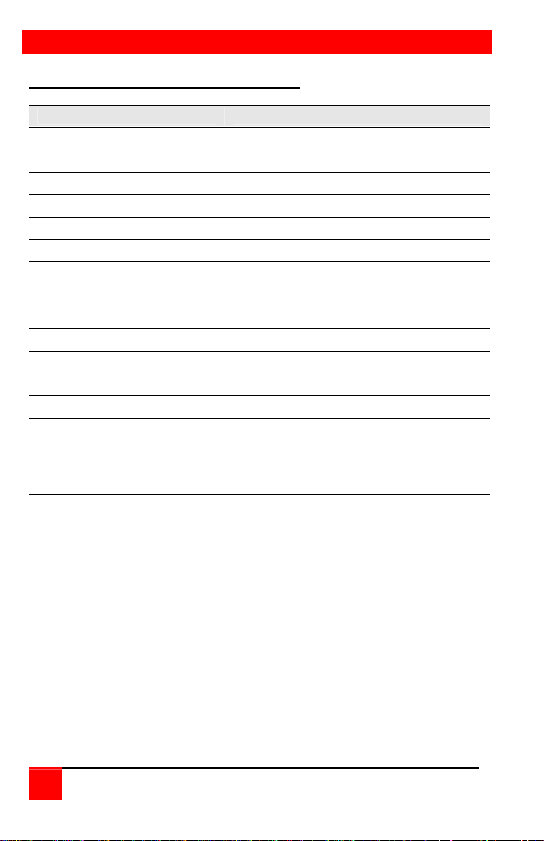
Appendix A. Initial factory settings
Setting Default Value
Foreground Color White
Background Color Blue
X-position 45
Y-position 90
Fadeout Time 20 seconds
Font 8 x 16 modern
Screen Saver Fireflies
Screen Saver Time 10 minutes
Maximum Ports 2 or 4
Scan enable Off
Scan Time Interval 5 seconds
Caps/Num lock/Scroll lock On
PC keyboard Mode 2
Typematic Value 43
Rate=10.9 chars/sec
Delay = 500 millisec.)
Mouse translation 0 (PS/2 mouse output)
Press and hold computer select buttons 1 and 2 and press the reset button
to reset the Vista switch to the factory settings listed. All other settings
remain unchanged.
26
Vista KVM-Series Installation and Operations Manual
Page 31
Appendix B. Parts and cables
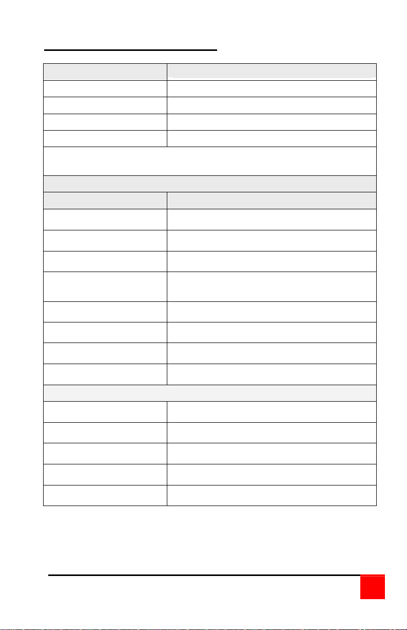
Vista Part Numbers Description
KVM-2/4PCA 2/4-port w/PC connectors
KVM-2/4UPH 2/4-port w/DB25 connectors
KVM-2UPMH 2-port (1-PC, 1-MAC) DB25 connectors
KVM-4UPMH 4-port (2-PC, 2-MAC) DB25 connectors
Note: KVM2UPMH has CPU port 2 pre-configured for MAC
KVM-4UPMH has CPU ports 3 & 4 pre-configured for MAC
CPU Adapter Cables for Models with DB25 Connectors
Part Number Description
CAB-CX0606Cnnn COAX SVGA HD15 - PS/2 MD6 Kbd/Ms
CAB-ZX0606Cnnn VGA HD15 - PS/2 MD6 Kbd/Ms
CAB-CXUSBCnnn COAX SVGA HD15 - USB Kbd/Ms to DB25 **
CAB-C1Y0509Cnnn COAX SVGA HD15 - AT DIN5 Kbd / DB9 Serial
Ms
CAB-VX0509Cnnn VGA HD15 - AT DIN5 Kbd / DB9 Serial Ms
CAB-C1V0400Cnnn COAX Apple VGA HD15 - ADB MD4 Kbd/Ms *
CAB-CXAV0400Cnnn COAX Apple DB15 - ADB MD4 Kbd/Ms *
CAB-AV0400Cnnn Apple DB15 - ADB MD4 Kbd/Ms *
CPU Adapter Cables for Models with PC Connectors
CAB-CXV66MMnnn COAX SVGA HD15 - PS/2 MD6 Kbd/Ms
CAB-ZXV66MMnnn VGA HD15 - PS/2 MD6 Kbd/Ms
CAB-CXUSB66MMnnn COAX SVGA HD15 - USB to PS/2 MD6 Kbd/Ms
CAB-CXV66MMnnn/AT COAX SVGA HD15 - w/ AT Kbd / Serial
KIT-KBPWR-5
Supplemental Power Kit for 2/4PCA models
Replace nnn with desired length.
*Available in standard lengths of 5, 10, and 20 feet
**Available in lengths of 5, 10, 20, 35, 50, 75, and 100 feet.
Vista KVM-Series Installation and Operations Manual
27
Page 32
Rackmount Kits
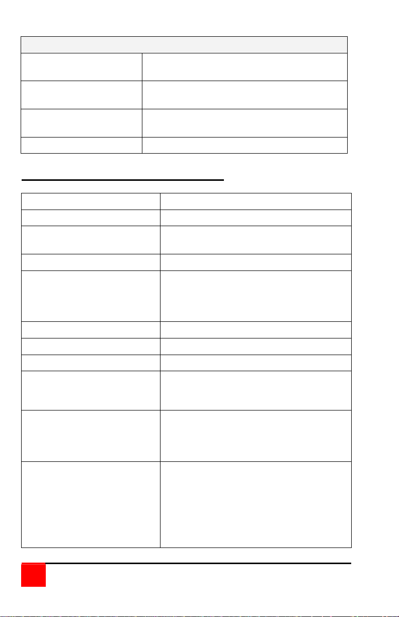
RM-UM19 Black anodized, for installation in 19"
racks.
RM-UM23 Black anodized, for installation in 23"
racks.
RM-UM24 Black anodized, for installation in 24"
racks.
Rm-UD-1U Under desk mounting kit
Appendix C. General specifications
Size 13.2" W x 1.75" H x 4.5" D
Weight 3 lb.
Environment 0 to 55°C., 0% to 80% non-condensing
relative humidity
Input Power Supplied by computers
CPU Connectors KVM-2UPH DB25 Female
KVM-4UPH DB25 Female
KVM-2PCA HD15F/MD6F/MD6F/DB9M
KVM-4PCA HD15F/MD6F/MD6F
Video Connector HD15F VGA video
Keyboard Connector MD6F / DIN5
Mouse Connector MD6F / DB9M
Chassis Fully shielded, black power coated
steel cover with polyester graphic
overlay panel
Controls Reset button
Computer select buttons:
2 port models - buttons 1-2
4 port models - buttons 1-4
Indicators Activity LED
Power LEDs:
2 port models LEDs 1-2
4 port models LEDs 1-4
Computer select LEDs:
4 port models LEDs 1-2
4 port models LEDs 1-4
28
Vista KVM-Series Installation and Operations Manual
Page 33
Appendix D. Rack mount instructions
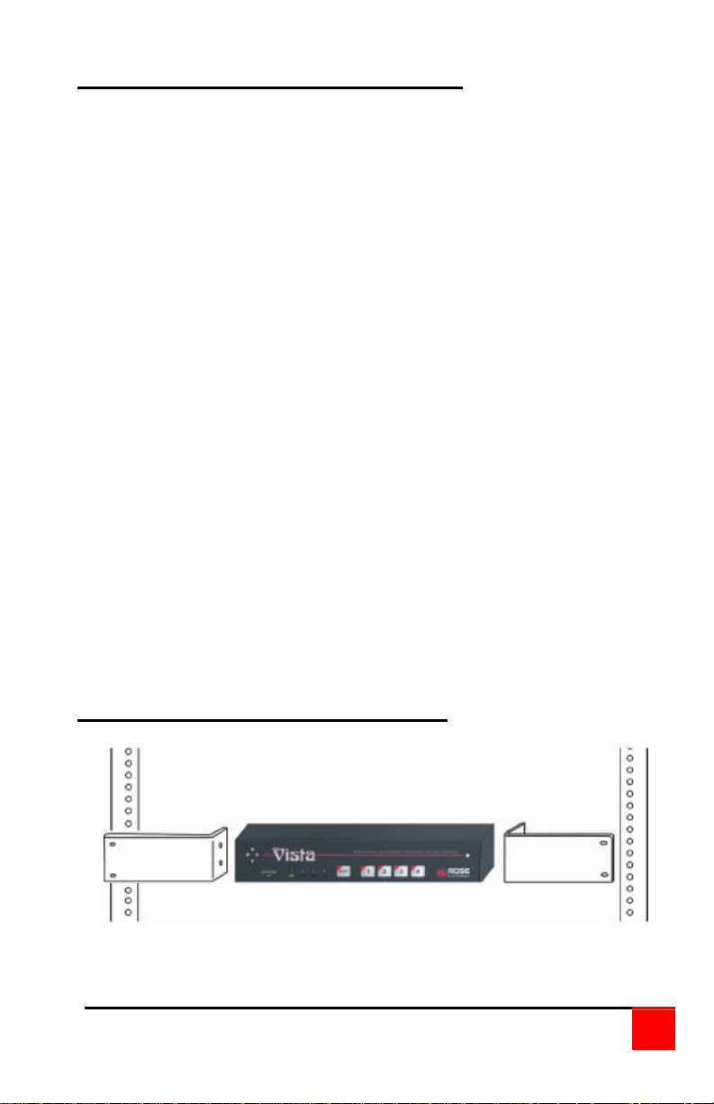
The optional rack mount kit includes the following items:
§ Two black anodized mounting brackets.
§ Four 6 - 32 x 3/8” flat head mounting screws.
To rack mount your Vista switch, attach the two rack mounting brackets to
your unit with the short flange against the unit using the four screws
provided. Using hardware other than that provided could cause damage
to the electronics and/or result in loss of mounting integrity. Do not over
tighten the screws used to mount the unit to the mounting brackets.
Secure the mounting brackets to the rack using the appropriate size bolts,
nuts and lock washers.
The following general guidelines should be observed when installing your
unit into a rack.
1. The Vista switch is designed to work in an ambient temperature of 0
to 55
ο
C (32
ο
F – 131ο F).
ο
C
2. Do not block power supply vents or otherwise restrict airflow when
rack-mounting this unit.
3. Mechanical loading of the rack should be considered to prevent
instability.
4. Tighten all connectors securely and provide adequate strain relief for
all cables.
5. Provide a grounded power source to all units. Pay special attention to
overall branch circuit load ratings before connecting equipment to this
source. Overloaded circuits are potential fire hazards and can cause
equipment failures or poor performance.
Appendix E. Rack mount illustration
Vista KVM-Series Installation and Operations Manual
29
Page 34
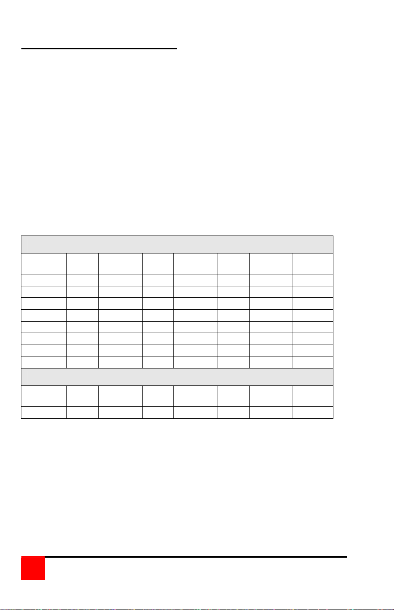
Appendix F. Typematic rate
Typematic Command
Press the left <Ctrl> key, type “A”, enter the typematic value (1-3 digit)
followed by <Enter>.
The typematic value is determined from the following tables using the
equation: Typematic Value = Rate value + Delay Value. Pick the desired
rate in keys/sec. and the delay in milliseconds from tables below. Add the
Rate Value and the Delay Value. The sum of these values is the typematic
value to enter.
For example to use a Rate of 16.0 keys/sec. and a 500 millisecond delay,
the Rate value = 7 and the Delay value = 32. Add 7 + 32 = 39. To set a
typematic value of 16, press the left <Ctrl> key, type “A”, enter 39, and
then press Enter.
Typematic Rate
Rate
Keys/sec
30.0 0 15.0 8 7.5 16 3.7 24
26.7 1 13.3 9 6.7 17 3.3 25
24.0 2 12.0 10 6.0 18 3.0 26
21.8 3 10.9 11 5.5 19 2.7 27
20.0 4 10.0 12 5.0 20 2.5 29
18.5 5 9.2 13 4.6 21 2.3 28
17.1 6 8.6 14 4.3 22 2.1 30
16.0 7 8.0 15 4.0 23 2.0 31
Delay* Delay
250 0 500 32 750 64 1000 96
* Delay in milliseconds
Rate
Value
Value
Rate
keys/sec
Rate
Value
Typematic Delay
Delay* Delay
Value
Rate
Keys/sec
Delay* Delay
Rate
Value
Value
Rate
Keys/sec
Delay* Delay
Rate
Value
Value
30
Vista KVM-Series Installation and Operations Manual
Page 35

Page 36

10707 Stancliff Road Phone: (281) 933-7673
Houston, Texas 77099 WWW.ROSE.COM
 Loading...