

Page 1
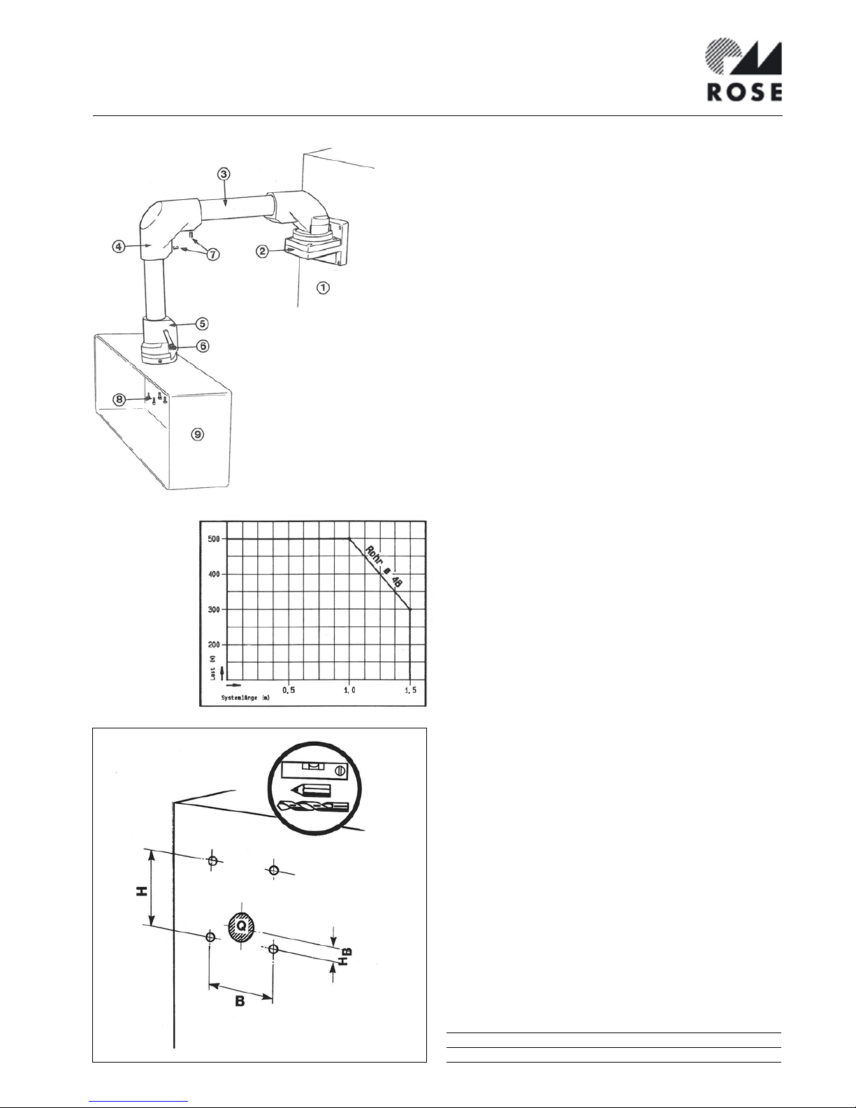
Montageanleitung Geräteträgersystem GT 48/2
Mounting instruction suspension system GT 48/2
Notice de montage système de suspension GT 48/2
Instruzioni di montaggio GT 48/2
Montage-aanwijzingen draagarmsysteem GT 48/2
1. Montagefläche
2. Wandgelenk W
(waagerecht)
3. Tragrohr
4. Winkel
5. Flanschkupplung
6. Klemmhebel
7. Schneidringschrauben
8. Befestigungsschraube
9. Steuertafel
1. Mounting area
2. Wall hinge W
(horizontal)
3. Carrying tube
4. Angle
5. Flange coupling
6. Clamb lever
7. Cutting screws
8. Mounting screws
9. Control panel
1. Superficie di fissaggio
2. Cerniera da parete W
(orizzontale)
3. Tubo portante
4. Angolo
5. Giunto a flangia / giunto
6. Manopola di blocco
7. Viti di serraggio
8. Viti di fissaggio frizione
9. Quadro di comando
1. Montagevlak
2. Wandscharnier W
3. Verbindingsbuis
4. Hoek
5. Flenskoppeling
6. Arretering
7. Tap-schroeven
8. Montagemoeren
9. Bedieningskast
Lastdiagramm
Load diagram
Diagramme de charge
Diagramma di carico
Belastingsdiagram
1. Surface de montage
2. Articulation murale W
(horizontale)
3. Tube porteur
4. Equerre
5. Flasque accouplement
6. Levier de blocage
7. Vis autotaraudeuses
8. Vis de fixation
9. Tableau de commande
1.0
Wandbefestigung
Befestigungsbohrungen anfertigen. Kabeldurchbruch max. 40 mm ø.
Wall mounting
Drill mounting holes. Opening for cable max. 40 mm ø.
Fixation murale
Perçage des trous de fixation. Passage de cable maxi ø 40 mm.
Fissaggio a parete
Interasse dei fori. Foro passagio cavi max. ø 40 mm.
Wandbevestiging
Gaten aanbrengen volgens schets. Sparing voor kabeldoorvoer is
max. 40 mm.
B H H
B
Q Durchgang Kernbohrung
85 95 20 40ø M8 9 6,5
Page 2
1.1
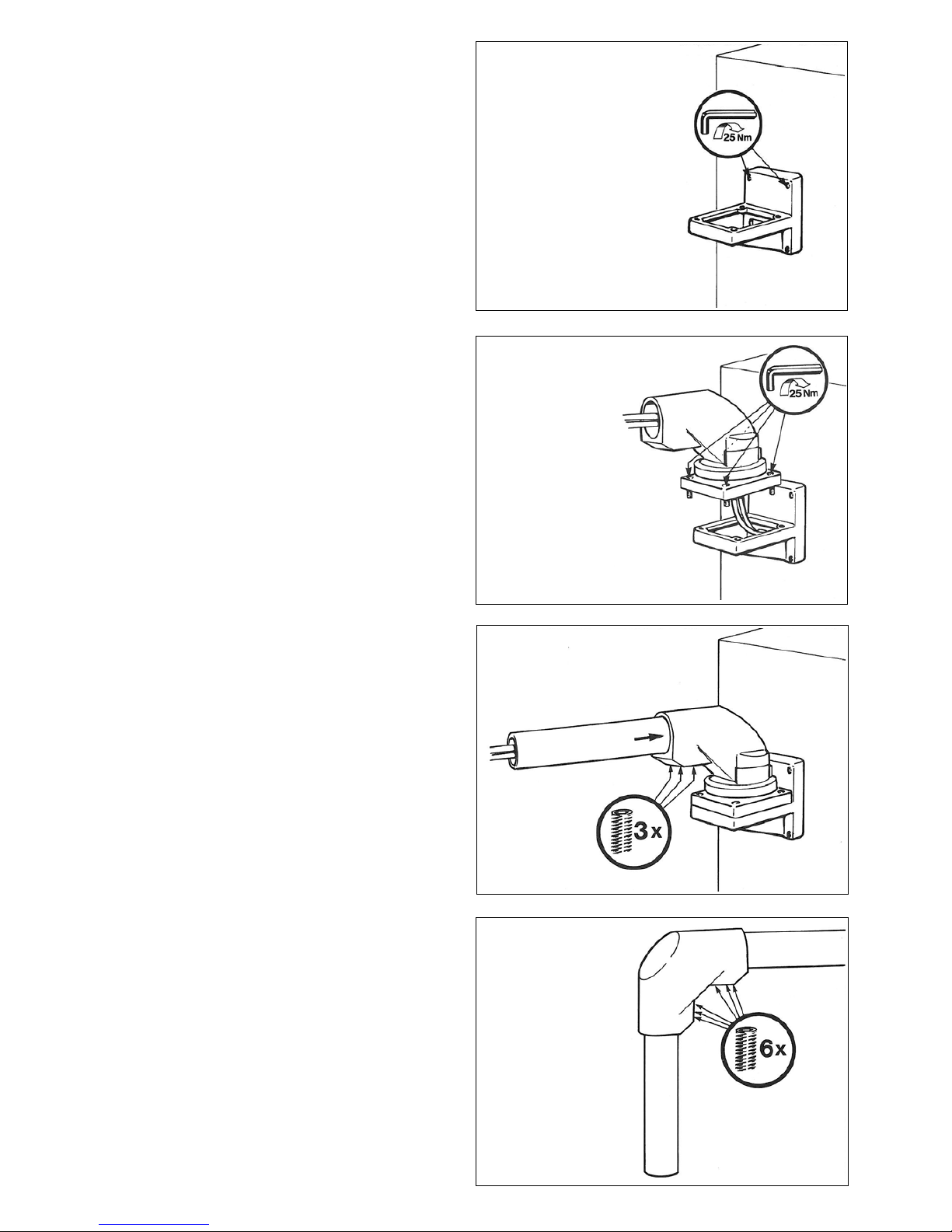
Wandgelenk W (waagerecht) demontieren und Gelenkträger befestigen.
Dismantle wall joint W (horizontal) and mount joint bracket.
Démonter l‘articulation murale W et fixer le support d‘articulation.
Smontare la cerniera W (orizzontale) e fissare la base alla parete.
Wandscharnier W demonteren en scharnierdrager monteren.
1.2
Kabel durchstecken und Wandgelenk montieren.
Feed cable through and mount wall joint.
Passer le cable et monter l‘articulation murale.
Infilare i cavi e montare la cerniera.
Kabel doorvoeren en scharnier monteren.
1.3
Tragrohr gewünschter Länge bis Anschlag einstecken und festschrauben.
Push carrying tube up to the limit into the wall joint and tighten the screws.
Insérer la section de tube horizontale jusqu‘à la butée et la visser.
Inserire il tubo della lunghezza desiderata sino al punto di blocco e serrare
le viti.
Verbindingsbuis invoeren tot aan aanslag en vastschroeven. (Buis vooraf op
de gewenste lengte brengen)
1.4
Kabel durch Winkel stecken und auf Tragrohr aufsetzen. Vertikales Tragrohr
einstecken, senkrecht ausrichten.
Durch Eindrehen der Schneidringschrauben (Pos. 7) sichern.
Feed cable through angle and push on to carrying tube. Also push the vertical
carrying tube into the joint and adjust the system vertically. After adjustment
lock with cutting screws into position (item 7).
Passer le cable au travers de l‘équerre et la fixer sur le tube horizontal. Insérer
le tube vertical, l‘ajuster et le fixer à l‘aide des vis autotaraudeuses (Pos. 7).
Far passare i cavi nell‘angolo e fissario al tubo. Inserire il tubo verticale e
serrare le viti (pos. 7).
Kabel door hoekstuk voeren en hoekstuk monteren aan horizontale verbindingsbuis. Vertikale buis monteren en uitrichten. Buis borgen door montage
van de zelftappende schroeven (pos. 7).
Page 3
1.5
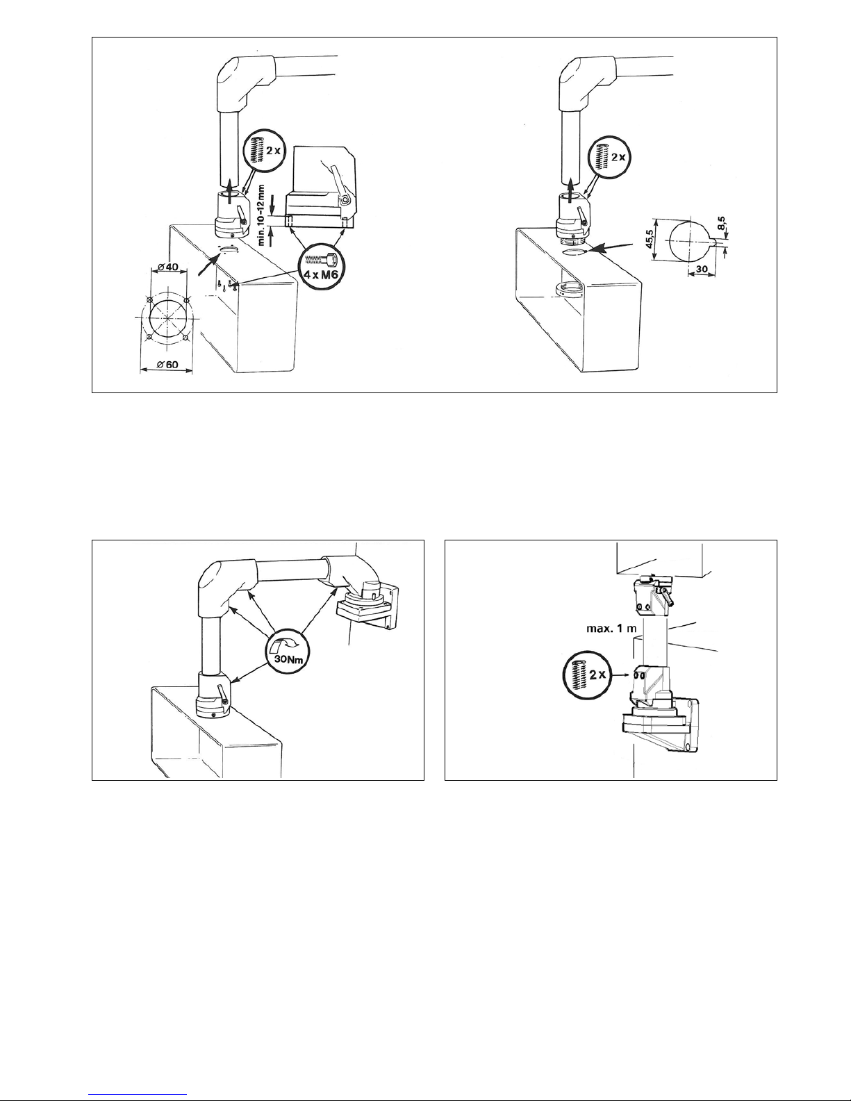
Flanschkupplung
Nullstellung des Drehbereichs überprüfen. Zur
Veränderung Kupplungsflansch drehen.
Flange coupling
Check the position of
rotating angle.
Suspension à flasque
Vérifier que le réglage
d‘angle de rotation soit
sur la bonne position.
Pour modifier la position,
faire pivoter la suspension à
flasque.
Frizione a flangia
Verificare il punto „0“ della
rotazione.
Flenskoppeling
Nulstelling van draaibereik
controleren. Dit is door de
koppelingsflens te draaien
eenvoudig te bewerkstelligen.
2.0
Wandgelenk S (senkrecht)
Befestigungsbohrungen anfertigen. Kabeldurchbruch max. 40 mm ø (siehe
Pos. 1.0). Wandgelenk montieren und Kabel durchstecken. Senkrechtes Tragrohr bis Anschlag einstecken und festschrauben.
Wall joint S (vertical)
Drill mounting holes. Cable hole max. 40 mm ø (see item 1.0). Mount wall
joint and feed cable through. Push vertical carrying tube up to the limit into
joint and tighten screws.
Articulation murale S (verticale)
Perçage des trous de fixation. Passage de cable maxi ø 40 mm (voir pos. 1.0).
Monter l‘articulation et passer le cable. Insérer le tube vertical jusqu‘à la
butée et le visser.
Cerniera da parete S (verticale) fare i fori di fissaggio e passaggio cavi come
pos. 1.0 (max. ø 40 mm). Montare la cerniera infilare i cavi nel tubo verticale
e fissare.
Wandscharnier S
Gaten aanbrengen als bij afbeelding 1.0. Kabel doorvoeren en wandscharnier
monteren. Vertikale buis tot aanslag invoeren en vastschroeven.
1.6
Nach dem Aufbau sind alle Schneidringschrauben (Pos. 7) mit 30 Nm anzuziehen. Der Drehwiderstand der Flanschkupplung ist mit dem Klemmenhebel
(Pos. 6) stufenlos einstellbar.
After assembly all cutting screws (item 7) have to be tightened with 30 Nm.
The friction of the flange coupling can be adjusted with the clamp lever.
Après montage, serrer les vis (Pos. 7) à 30 Nm. La force nécessaire à la rotation
est réglable par levier (Pos. 6).
Completato il montaggio serrare le viti (pos. 7) con forza max 30 Nm.
L‘angolo di rotazione puo‘ essere regolata con la manopola (pos. 6) sino al
blocco.
Nadat het geheel gemonteerd is de tapschroeven (pos. 7) aandraaien
(aandraaimoment 30 Nm).
Page 4
3.0
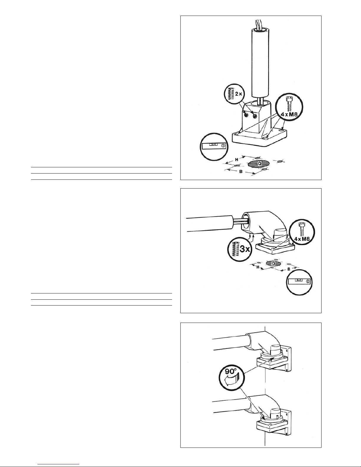
Standfuß/Standfuß drehbar, stehende/hängende Befestigung
Befestigungsbohrungen anfertigen. Kabeldurchbruch max. 40 mm ø. Auf
winklige Ausrichtung achten.
Achtung: Bei Montage des Standfußes/Standfußes drehbar müssen die
Schneidringschrauben (Pos. 7) in Lastrichtung zeigen!
Foot turnable/non-turnable, upright/hanging
Drill mounting holes. Opening hole for cable max. 40 mm ø. Watch for correct and straight positioning.
Please note: Cutting screws from foot turnable/non-turnable, have to be
positioned into the direction of the load.
Pied fixe/pied pivotant. Fixation au sol ou au plafond
Perçage des trous de fixation. Passage de cable maxi ø 40 mm. Vérifier et
ajuster l‘èquerrage.
Attention: lors du montage du pied fixe/pied pivotant, les vis auto-taraudeuses (Pos. 7) doivent être orientées vers la charge.
Base/base con rotazione e fissaggio a terra o sospesa
Forare rispettando gli interassi indicati. Foro passaggio cavi max. ø 40 mm.
Controllare la perpendicolarita.
Attenzione: nel montaggio della base/base con rotazione le viti di fissaggio
pos. 7 devono risultare perpendicolari al carico.
Standvoet/standvoet, draaibaar. Stande of hangende montage.
Gaten aanbrengen volgens schets. Sparing voor kabeldoorvoer is maximaal
40 mm. Denk aan uitrichten.
Let op: Bij montage van de (draaibare) standvoet moeten de zelftappende
schroeven (pos. 7) in de lastrichting wijzen.
4.0
Aufsatzgelenk, stehende/hängende Befestigung
Befestigungsbohrungen anfertigen. Kabeldurchbruch max. 40 mm ø. Auf
winklige Ausrichtung achten. Weiterer Aufbau siehe Pos. 1.3
Top mounted joint, upright/hanging position
Drill holes for mounting. Hole for cable 40 mm ø. Watch for correct and
straight positioning to continue with item 1.3
Rotor, fixation au sol ou au plafond
Perçage des trous de fixation. Passage de cable maxi. ø 40 mm. Vérifier et
ajuster l‘équerrage. Instructions complémentaires, voir Pos. 1.3
Flangia ad angolo - fissaggio al piano o sospesa
Forare rispettando gli interassi indicati foro passaggio cavi max. ø 40 mm.
Controllare la perpendicolarita. Procedere come al punto 1.3
Opzetscharnier, staande/hangende montage
Gaten aanbrengen volgens schets. Sparing voor kabeldoorvoer is maximaal
40 mm. Denk aan uitrichten. Verdere opbouw vanaf punt 1.3
5.0
Schwenkwinkelveränderung
Der Schwenkwinkel bei Wandgelenk W/S, Aufsatzgelenk und Standfuß drehbar ist im 90° Raster veränderbar. Hierzu das Gelenkoberteil abschrauben (4 x
M8), den gewünschten 90° Raster verdrehen und wieder befestigen.
Changing rotation stop
The rotation stop of wall joint W/S, base bracket and foot can be changed
every 90°. To do this remove upper part of the joint (4 x M8), turn the disc
into the required position and lock it again.
Modification de l‘angle de rotation
L‘angle de rotation des articulations murales W et S, rotor et pied pivotant
est réglable sur 90°. Démonter la partie supérieure de l‘articulation (4 x M8),
régler l‘angle sur la position souhaitée et remonter l‘articulation.
Anello di regolazione
L‘anello di regolazione per le cerniere a parete W/S, la base e la flangia ad
angolo permette di bloccare la rotazione a 90°. Per inserirlo e‘ sufficiente
smontare la parte superiore della cerniera (4 x M8), inserire l‘anello posizionando i 90° secon do l‘esigenza e rimontare ik cordo superiore.
Veranderen van de draaihoek
De draaihoek bij het wandscharnier W/S, opzetscharnier en draaibare standvoet is in stappen van 90° te veranderen. Hiervoor dient u het bovendeel van
het scharnier te demonteren (4 x M8), de gewenste draaihoek instellen en
het bovendeel weer monteren.
B H Q
80 80 40ø M8
B H Q
80 80 40ø
92148 DC 06/2011 20.000
 Loading...