

Page 1
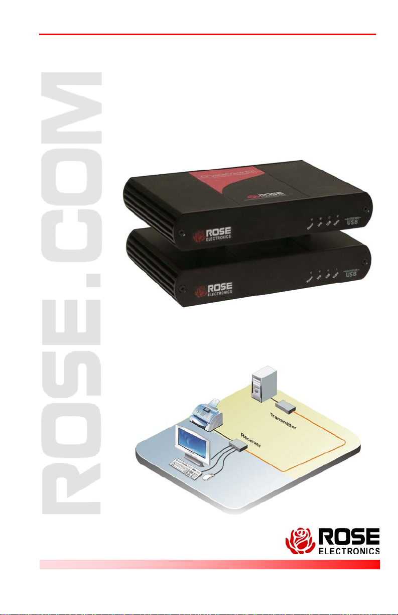
CrystalView EX5
IN S TALL ATI O N AN D
MANUAL
CATx Extender
OPERATIONS
10707 Stancliff Road Phone: (281) 933-7673
Houston, Texas 77099 WWW.ROSE.COM
Page 2

Limited Warranty
Rose Electronics warrants the CrystalView EX5 to be in good working order for one year from the
date of purchase from Rose Electronics or an authorized dealer. Should this product fail to be in good
working order at any time during this one-year warranty period, Rose Electronics will, at its option,
repair or replace the Unit as set forth below. Repair parts and replacement units will be either
reconditioned or new. All replaced parts become the property of Rose Elect ronics. Th is limited
warranty does not include service to repair damage to the Unit resulting from accident, disaster,
abuse, or unauthorized modification of the Unit, including static discharge and power surges.
Limited Warr an ty ser vi ce may be obtained by delivering this unit during the one-year warranty period
to Rose Electronics or an authorized repair center providing a proof of purchase date. If this Unit is
delivered by mail, y ou agree to ins ure the Unit or assume the r isk of loss or da m age in trans it, to
prepay shipping charges to the warranty service location, and to use the original ship ping con tain er or
its equivalent. You must call for a return authorization number first. Under no circumstances will a unit
be accepted without a return authorization number. Contact an authorized repair center or Rose
Electronics for further information.
ALL EXPRESS AND IMPLIED WARRANTIES FOR THIS PRODUCT INCLUDING THE
WARRANTIES OF MERCHANTABILITY AND FITNESS FOR A PARTICULAR P URPOS E, ARE
LIMITED IN DURATION TO A PERIOD OF ONE YEAR FROM THE DATE OF PURCHASE, AND NO
WARRANTIES, WHETHER EXPRESS OR IMPLIED, WILL APPLY AFTER THIS PERIOD. SOME
STATES DO NOT ALLOW LIMITATIONS ON HOW LONG AN IMPLIED WARRANTY LASTS, SO
THE ABOVE LIMITATION MAY NOT APPLY T O YOU.
IF THIS PRODUCT IS NOT IN GOOD WORKING ORDER AS WARRANTED ABOVE, YOUR SOLE
REMEDY SHALL BE REPLACEMENT OR REPAIR AS PROVIDED ABOVE. IN NO EVENT WILL
ROSE ELECTRONICS BE LIABLE TO YOU FOR ANY DAMAGES INCLUDING ANY LOST
PROFITS, LOST SAVINGS OR OT HER INCIDENTAL OR CONSEQUENTIAL DAMAGES ARISING
OUT OF THE USE OF OR THE INABILITY TO USE SUCH PRODUCT, EVEN IF ROSE
ELECTRONICS OR AN AUTHORIZED DEALER HAS BEEN ADVISED OF THE POSSIBILITY OF
SUCH DAMAGES, OR FOR ANY CLAIM BY ANY OTHER PARTY.
SOME STATES DO NOT ALLOW THE EXCLUSION OR LIMITATION OF INCIDENTAL OR
CONSEQUENTIAL DAMAGES FOR CONSUMER PRODUCTS, SO THE ABOVE MAY NOT APPLY
TO YOU. THIS WARRANTY GIVES YOU SPECIFIC LEGAL RIGHTS AND YOU MAY ALSO HAVE
OTHER RIGHTS WHICH MAY VARY FROM STATE TO STATE.
NOTE: This equipment has been tested and found to comply wit h the limits f or a Class B digital
device, pursuant to Part 15 of the FCC Rules. These limits are designed to provide reasonable
protection against harmful interference when the equipment is operated in a comme rcial envi ronment.
This equipment generates, uses, and can radiate radio frequency energy and, if not installed and
used in accordance with the instruction manual, may ca use harmful interfere nce to radio
communications. O peration of this equipment in a resi dential area is likely to cause harm ful
interference in which case the user will be required to correct the interference at his own expense.
IBM, AT, and PS/2 are tr ademarks of I nternatio nal Busines s M achines Corp. Microsoft and Micros oft
Windows are registered trademarks of Microsoft Corp. Any other trademarks mentioned in this
manual are acknowledged to be the property of the trademark owner.
Copyright Rose Electronics 2011. All rights reserved.
No part of this manual may be reproduced, stored in a retrieval system, or transcribed in any form or any
means, electronic or mechanical, including photocopying and recording, without the prior written permission
of Rose Electronics.
Rose Electronics Part # MAN-CRVEXT5
Printed In the United States of America – Revision
Page 3

FCC/IC STATEMENTS, EU DECLAR ATION OF CONF ORMITY
FCC Radio Frequency Interference
This device complies with FCC Part 15 Subpart B. of the FCC rules;
operation is subject to the following two conditions:
1. This device may not cause harmful interference
2. This device must accept any interference received, including
interference that may cause undesired operation.
CE Statement
This product meets European Standard EMC EN-55022 Class A,
EN 61000, and EN 55024
IC Statement
This Class A digital apparatus complies with Canadian ICES-003.
Page 4

Table of Contents
Contents Page #
Disclaimer ...................................................................................................... 1
System Introduction ....................................................................................... 1
Features ......................................................................................................... 2
Package Contents ......................................................................................... 2
Additional Installation Items ........................................................................... 3
Rose Electronics web site.............................................................................. 3
Product Registration ...................................................................................... 3
System Overview ........................................................................................... 3
Models ........................................................................................................... 4
Transmitter - Front Panel ........................................................................... 5
Transmitter - Rear panel Connectors ......................................................... 5
Receiver - Front Panel ............................................................................... 6
Receiver - Rear Panel ................................................................................ 6
System Installation ......................................................................................... 7
Transmitter installation ............................................................................... 7
Receiver installation ................................................................................... 8
Installation Verification ............................................................................... 8
Connecting USB Devices ........................................................................... 9
System Operation .......................................................................................... 9
System Troubleshooting .............................................................................. 10
Product Safety ............................................................................................. 12
Maintenance and Repair.............................................................................. 13
Technical Support ........................................................................................ 13
Figures Page #
Figure 1. Models ............................................................................................ 4
Figure 2. Typical Installation .......................................................................... 7
Tables Page #
Table 1. Transmitter Indicators/Connectors .................................................. 5
Table 2. Receiver Indicators / Connectors .................................................... 6
Appendices Page #
Appendix A – General Specifications .......................................................... 14
Page 5

INTRODUCTION
Disclaimer
While every precaution has been taken in the preparation of this manual, the
manufacturer assumes no responsibility for errors or omissions. Neither
does the manufacturer assume any liability for damages resulting from the
use of the information contained herein. The manufacturer reserves the
right to change the specifications, functions, or circuitry of the product
without notice.
The manufacturer cannot accept liability for damages due to misuse of the
product or other circumstances outside the manufacturer’s control. The
manufacturer will not be responsible for any loss, damage, or injury arising
directly or indirectly from the use of this product.
System Introduction
Thank you for choosing the CrystalView EX5 extender from Rose
Electronics for your remote accessing needs. The CrystalView EX5 system
consists of a Transmitter unit and a Receiver unit. The Transmitter unit
connects to your computer’s DVI-D and USB Type A connectors using the
provided DVI and USB cables. The Receiver unit connects to your
workstation. The Transmitter and Receiver units are connected together
with industry standard CAT5e or better cable. This provides access to your
computer from up to 330 feet (100m) away.
The CrystalView EX5 extender complies with USB 1.1 and USB 2.0
specifications and supports USB 1.1 and low bandwidth USB 2.0
devices. It is ideal for use in industrial control areas, digital signage,
connecting cameras for security systems, USB device printing, scanning
and storage.
If additional USB devices are needed, you can add up to 4 USB hubs to
the three port Receiver model and connect up to 13 USB devices.
The CrystalView EX5 supports all major operating systems including
Windows
USB printers, scanners, web cameras, USB hard drives, flash drives, MP3
players and more can easily be connected to the Receiver unit.
Since there are a number of factors that effect the operation of the
CrystalView EX5, not all devices are compatible with this product.
®
, MAC®, and Linux
®
CrystalView EX5 Installation and Operations Manual 1
Page 6

Features
Supports CAT5e cable distances up to 330 feet (100m)
Supports uncompressed HD DVI video with resolutions up to
1920 x 1200
(Resolution does not degrade over CAT5e distance)
USB Host support – EHCI (USB 2.0) and OHCI/UHCI (USB 1.1)
Supports USB 2.0 (high-speed at reduced bandwidth),
USB 2.0 and 1.1 (Full-speed), and
USB 2.0 and 1.1 (Low-speed)
3-USB ports available on the Receiver unit
Standard USB hubs can be used to increase the maximum number of
connected USB devices to 13 and 4 USB hubs.
Up to 500 mA of power is available at each USB port on the Receiver
for powering high-power USB devices
Plug-and-Play instal lation, no configuration or set-up needed.
Installation consists of:
1. Connecting the Receiver to your DVI monitor, USB keyboard and
mouse, headphone, microphone and USB device(s)
2. Connect the Transmitter to your computer’s DVI video port and
USB port.
3. Connect the Transmitter to the Receiver using standard CAT5e*
cable
4. Apply power and the installation is complete.
The Transmitter unit requires a +5VDC power adapter (included).
The Receiver unit requires a +5VDC power adapter (included).
* CAT5e or better cable, Solid core CAT6 STP cable is recommended
Package Contents
Transmitter unit
Receiver unit
5V, 3A power adapter (Transmitter)
5V, 3A power adapter (Receiver)
USB Type A to Type B cable (6 ft)
DVI cable (male to male- 5 ft)
Product Manual
2 CrystalView EX5 Installation and Operations Manual
Page 7

Additional Installation Items
Computer with DVI-D/DVI-I outp ut
USB 1.1 or 2.0 host computer
1 - CAT5e cable (Transmitter to Receiver – Point-To-Point)
USB 1.1 or 2.0 compatible devices
Rose Electronics web site
Visit our web site at www.rose.com for additional information on the
CrystalView EX5 and other products offered by Rose Electronics that are
designed for data center applications, classroom environments, digital
wall/signage displays, industrial / military systems, and many other access
and switching applications.
Product Registration
Take advantage of the following when you register your Rose Electronics
products online at www.rose. com/htm/online-registrationform.htm.
Rose Electronics standard warranty Plus . . . .
Free Lifetime Firmware Updates
Free Lifetime Technical Support
30 day Money Back Guarantee
Priority “First-In-Line” Status for Technical Support
System Overview
The CrystalView EX5 is a very versatile and flexible system that can be
easily and quickly installed. You can position your computer anywhere
within 330 feet of the Receiver unit and access and control it as if you were
directly connected to the computer. You can control and use a USB
keyboard, USB mouse, webcam, flash drive, USB speakers, microphone
and other compatible USB devices.
The versatility of the CrystalView EX5 makes it ideal for security, medical,
signage, and industrial applications where remote access is required.
The Receiver unit has 3 USB Type A connectors. These are usually
connected to a USB mouse, USB keyboard, and a USB HUB. The
CrystalView EX5 supports up to 13 USB devices and 4 HUB levels.
CrystalView EX5 Installation and Operations Manual 3
Page 8
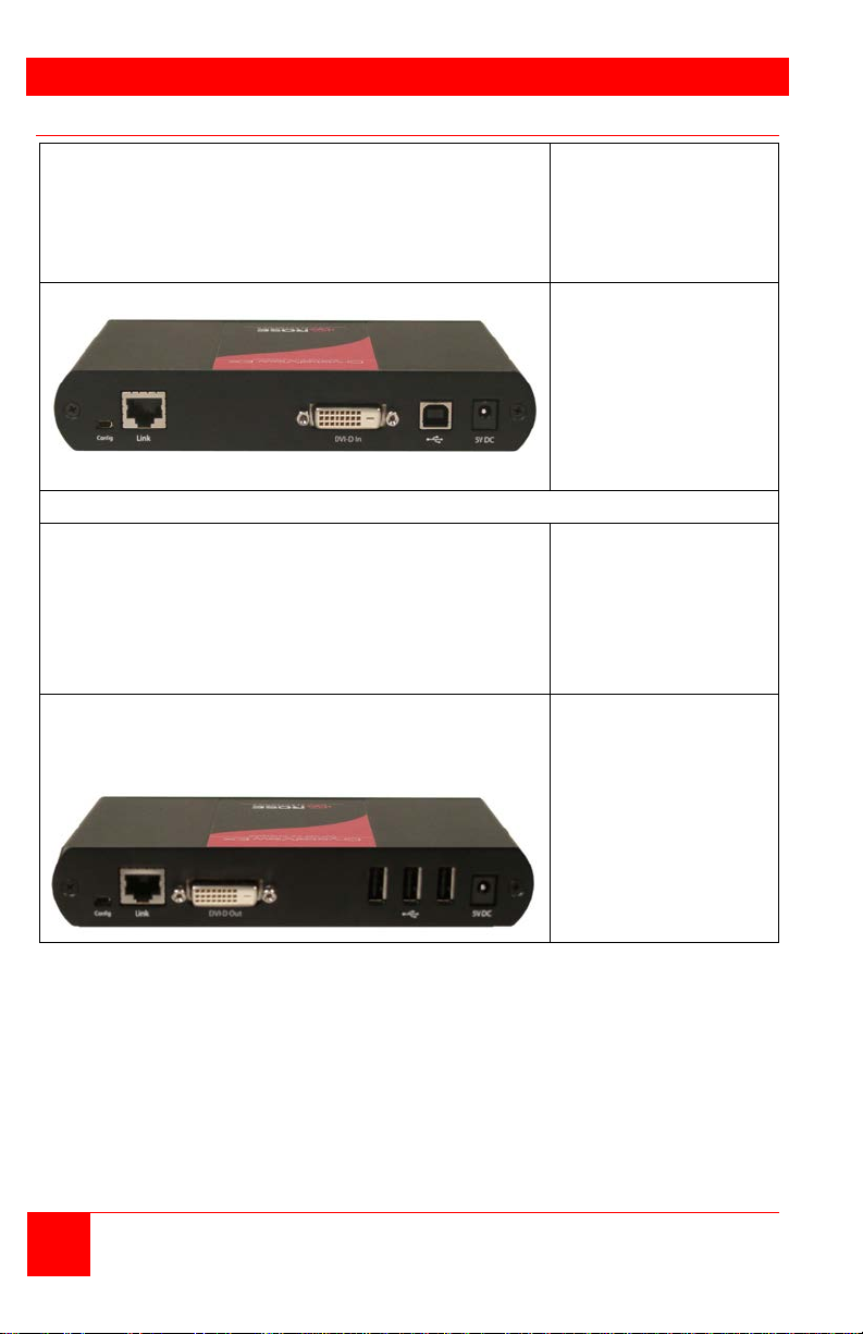
MODELS
Transmitter – Front View
Indicators
Transmitter – Rear View
Connectors
Receiver – Front View
Indicators
Receiver – Rear View
Connectors
Models
Power
Link
USB
Video
DVI-D In
Config
USB Type B
Link
Power (+5V / 3A)
Power
Link
USB
Video
DVI-D Out
Headphone Out
Microphone In
Config
Link
Power (+5V / 3A)
Figure 1. Models
4 CrystalView EX5 Installation and Operations Manual
Page 9
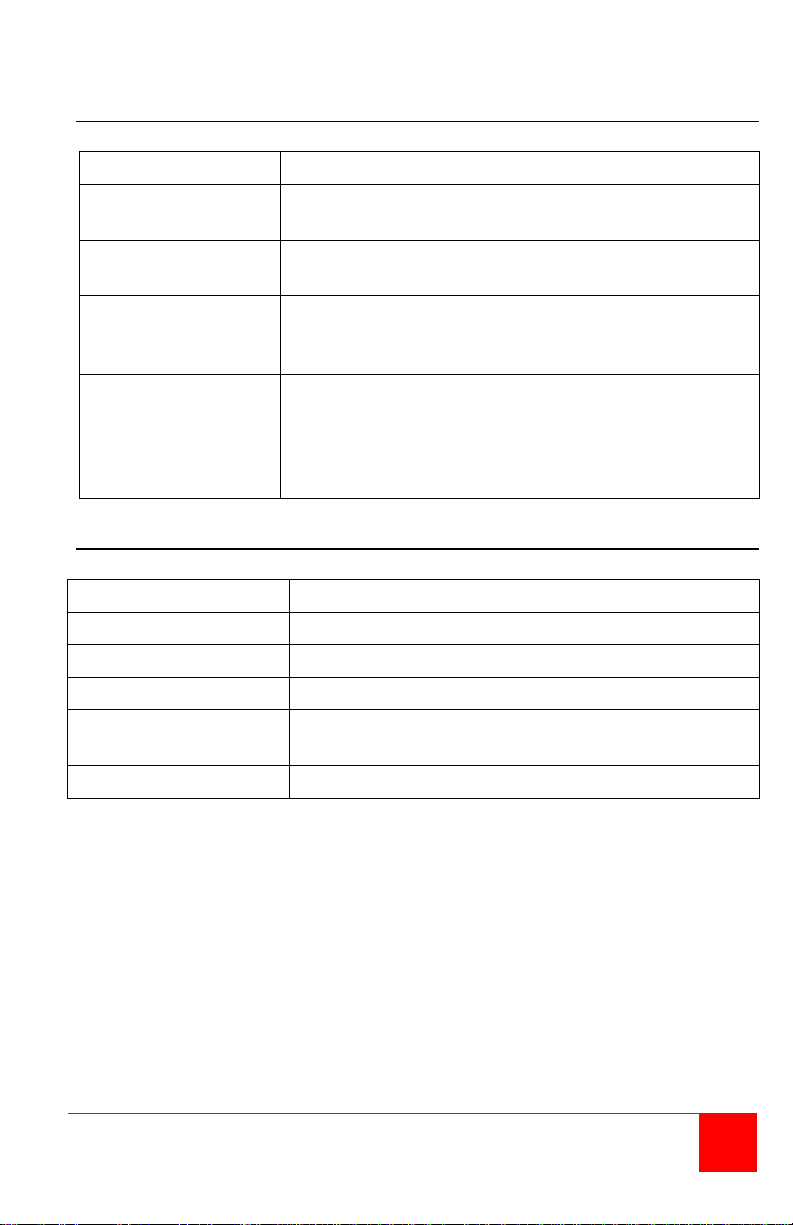
Indicator
Description
Power
(Green LED)
On = Ready / Off = No power /
Link
(Green LED)
On = Valid Link between Transmitter and Receiver
Off = No Link
USB
On = Properly enumerated on host computer
Blinking = host is in suspend mode
Video
On = Valid HDCP activity between the Transmitter
between the Transmitter and Receiver
Connector
Description
DVI-D In
DVI-D Video Input from Host computer (Supplied)
Config
Reserved for company use only
USB Type B
USB input from Host computer (Supplied)
Link (RJ45)
Connection for a CAT5e or better cable to the
Receiver unit
Power
+5V, 3A power adapter (Supplied)
Transmitter - Front Panel
(Green LED)
(Green LED)
Transmitter - Rear panel Connectors
Table 1. Transmitter Indicators/Connectors
Off = No Link
and host computer
Off = No Video activity
Blinking = Normal video is being transmitted
CrystalView EX5 Installation and Operations Manual 5
Page 10
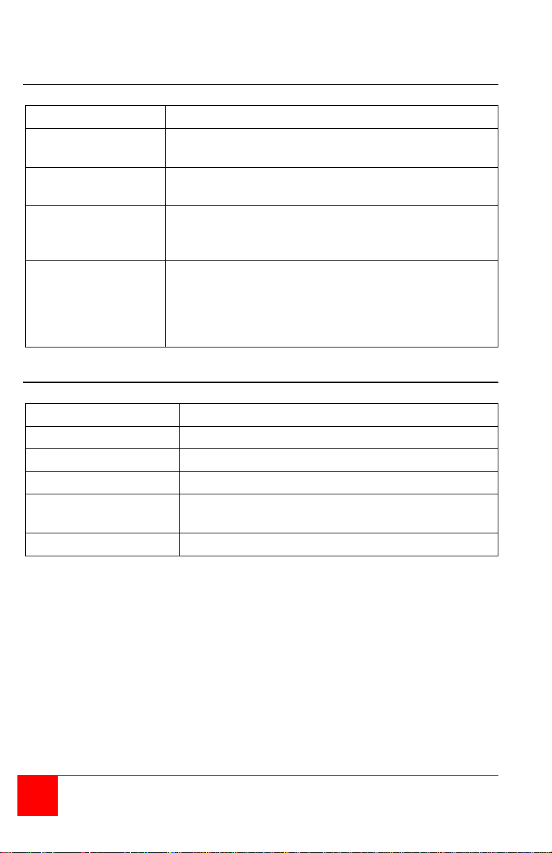
Indicator
Description
Power
(Green LED)
On = Ready / Off = No Link
Link
(Green LED)
On = Valid Link between Transmitter and Receiver
Off = No Link
USB
On = Properly enumerated on host computer
Blinking = host is in suspend mode
Video
On = Valid HDCP activity between the Transmitter
between the Transmitter and Receiver
Connector
Description
DVI-D Out
DVI-D Video connector to the monitor
Config
Reserved for company use only
USB Type A
Connection (3) for remote USB devices
Link (RJ45)
Connection for a CAT5e or better cable to the
Transmitter unit
Power
+5V, 3A power adapter (Supplied)
Receiver - Front Panel
(Green LED)
(Green LED)
Receiver - Rear Panel
Table 2. Receiver Indicators / Connectors
Off = No Link
and host computer
Off = No Video activity
Blinking = Normal video is being transmitted
6 CrystalView EX5 Installation and Operations Manual
Page 11
INSTALLATION
System Installation
Before installing the CrystalView EX5, pre-plan the layout of the computer,
the Transmitter, the Receiver, and the equipment that will be connected to
the Receiver. The Transmitter and Receiver units should be in a location
that is easily accessible. The CAT5e cable should be routed away from
equipment or environments that can cause interference with the data
transmission between the Transmitter and Receiver.
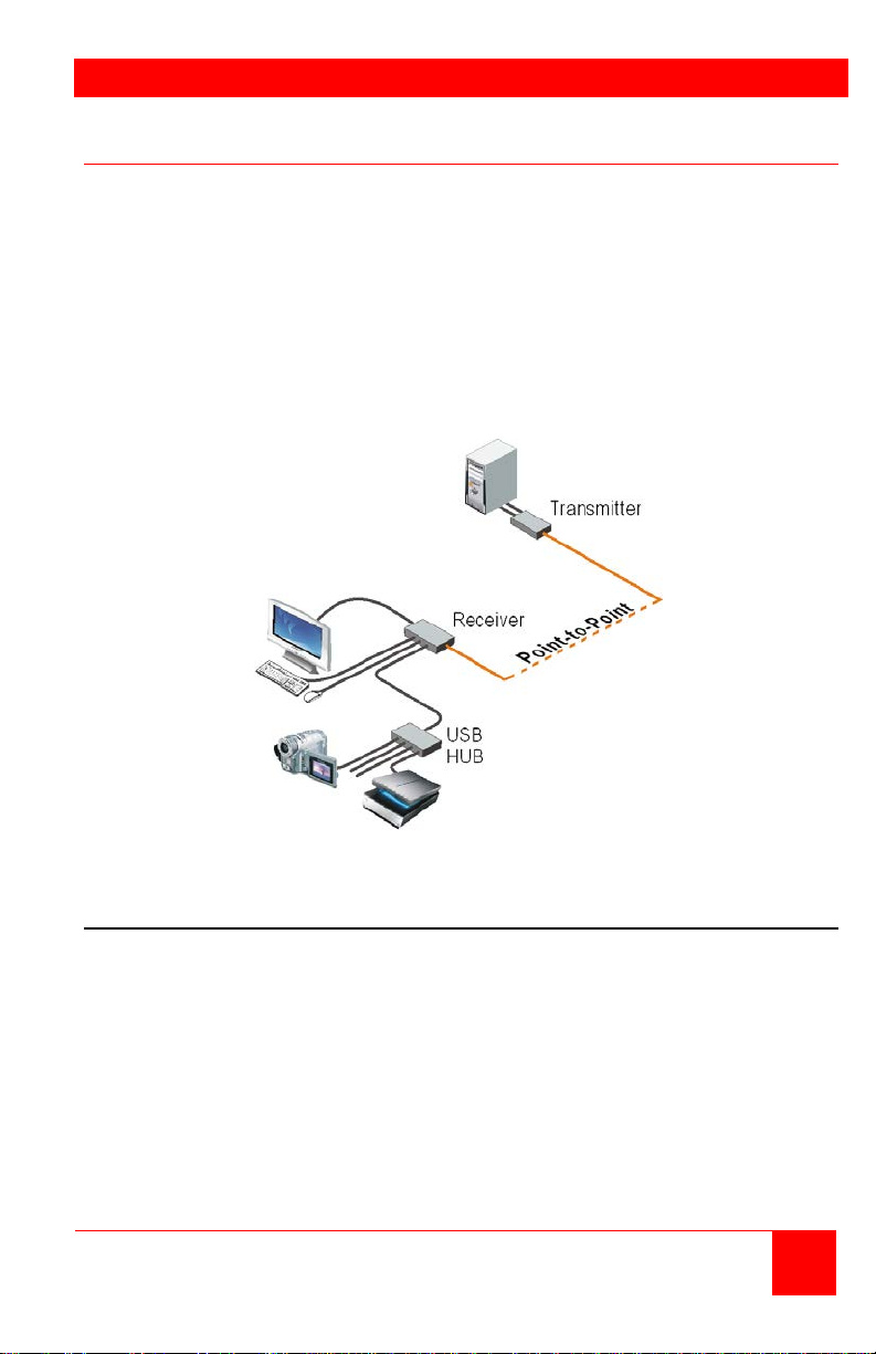
The CrystalView EX5 is installed in a “Point-To-Point” configuration. This is
easily done by connecting a CAT5e* cable (330 ft / 100m) directly from the
Transmitter’s RJ45 port to the Receiver’s RJ45 port.
Figure 2. Typical Installation
Transmitter installation
(Refer to Figure 2)
1. Locate the Transmitter unit near the computer.
2. Connect the supplied USB Type A/B cable to the Transmitter unit’s USB
Type B port and to an available USB (1.1 or 2.0) Type A port on the
computer.
3. Connect the supplied DVI cable to the Transmitter unit’s DVI-D port and
to the DVI video port on the computer.
4. Connect a CAT5e* cable (not supplied) from the Transmitter’s RJ45 port
to the Receiver’s (RJ45) connector.
5. Connect the supplied 5V, 3A power adapter to an AC outlet and to the
Transmitter’s power port.
CrystalView EX5 Installation and Operations Manual 7
Page 12

Receiver installation
(Refer to Figure 2)
1. Locate the Receiver unit near the monitor and USB devices.
2. Connect a DVI monitor cable to the DVI-D out connector on the
Receiver’s rear panel.
3. Connect your USB devices to the 3 USB Type A ports on the rear panel
of the Receiver. Normally these USB ports are connected to a USB
keyboard, USB mouse, and a USB Hub.
4. Connect the CAT5e* cable (not supplied) from the Transmitter’s RJ45
port to the Receiver’s RJ45 connector.
5. Connect the supplied 5V, 1A power adapter to an AC outlet and to the
Receiver’s power port.
* CAT5 cable – It is recommended that only CAT5e or better, UTP cabling
be used to connect the Transmitter and Receiver units
together. The CAT5e cabling must have straight-through
conductors with no crossovers and terminated with 8
conductor RJ45 connectors at each end. The maximum
CAT5e cable length for a point-to-point configuration is
330 feet (100 meters).
Installation Verification
The Power, Link, Video, and USB LEDs on the Transmitter and Receiver
units will provide information regarding the installation, cabling, video, and
other items. Verify that the LEDs are registering properly.
(Refer to Table 2 and Table 3)
If the Link LED is off, the CAT5e cable from the Transmitter and Receiver
are not connected.
The Power LED should be solid green. If it is off the system is not ready.
8 CrystalView EX5 Installation and Operations Manual
Page 13

Connecting USB Devices
Up to 13 USB 1.1 or 2.0 devices can be connected to the Receiver unit
using USB Hubs. Normally the three USB Type A connectors on the
Receiver are connected to a USB Keyboard, USB mouse, and a USB Hub.
Installing your USB devices is no different than installing them when
connected directly to a computers USB port.
1. Install the USB device according to the manufactures procedure and
any required software to operate the USB device
2. Connect the USB device to the Receiver’s USB ports or a HUB port
3. Verify that the operating system has recognized the USB device and, if
needed, installed the proper drivers to operate the USB device
4. Test the USB device
Each USB Type A port on the Receiver unit can supply up to 500ma to a
USB device or USB Hub. When connecting additional USB devices through
a USB Hub, consider the total current needed to operate all of the USB
devices. If the total power is greater than 500ma, use a powered Hub to
supplement the power to the devices.
The CrystalView EX5 is compatible with a wide variety or graphic cards,
monitors, USB devices, and operating systems.
System Operation
The operation of the CrystalView EX5 is no different than operating your
computer with your keyboard, monitor, mouse, and USB devices directly
connected to it. The only difference is the computer can be located
anywhere within 330 feet from the Receiver unit. Applications can be
executed, files opened, edited, and saved, upgrades can be performed and
normal system operations can be performed as if you were directly
connected to your computer.
CrystalView EX5 Installation and Operations Manual 9
Page 14

TROUBLESHOOTING
System Troubleshooting
All LEDs on the Transmitter or Receiver are off
Check the DC power adapter connection to the Unit
Verify there is power at the power source
Link LED on the Transmitter and Receiver are off
Check the CAT5e Link connections on the Transmitter and Receiver
Video and/or USB performance is not satisfactory
High amount of network traffic, reduce the number of CrystalView EX5
units on the network or reduce the network traffic.
Graphic/video settings do not list the specific resolution
Up to date video drivers are not installed
Resolution is not supported (See Appendix B)
The CrystalView EX5 Transmitter and Receiver indicators will provide
information about the operation, connectivity and data transmission.
Observe these indicators and refer Table 1 and Table 2 for a description of
the indicator states.
10 CrystalView EX5 Installation and Operations Manual
Page 15

Page 16

SAFETY
Product Safety
The CrystalView EX5 extender has been tested for conformance to safety
regulations and requirements, and has been certified for international use.
Like all electronic equipment, the CrystalView EX5 should be used with
care. To protect yourself from possible injury and to minimize the risk of
damage to the Unit, read and follow these safety instructions.
Follow all instructions and warnings marked on this Unit.
Except where explained in this manual, do not attempt to service this
Unit yourself.
Do not use this Unit near water.
Assure that the placement of this Unit is on a stable surface or rack
mounted.
Provide proper ventilation and air circulation.
Keep power cord and connection cables clear of obstructions that might
cause damage to them.
Use only power cords, power adapter and connection cables designed
for this Unit.
Use only a grounded (three-wire) electrical outlet.
Use only the power adapter provided with the Cr ystalV i e w EX5.
Keep objects that might damage this Unit and liquids that may spill, clear
from this Unit. Liquids and foreign objects might come in contact with
voltage points that could create a risk of fire or electrical shock.
Operate this Unit only when the cover is in place.
Do not use liquid or aerosol cleaners to clean this Unit. Always unplug
this Unit from its electrical outlet before cleaning.
Unplug this Unit from the electrical outlet and refer servicing to a
qualified service center if any of the following conditions occur:
The power cord or connection cables are damaged or frayed.
The Unit has been exposed to any liquids.
The Unit does not operate normally when all operating instructions
have been followed.
The Unit has been dropped or the case has been damaged.
The Unit exhibits a distinct change in performance, indicating a need
for service.
12 CrystalView EX5 Installation and Operations Manual
Page 17

MAINTENANCE AND SUPPORT
Maintenance and Repair
This Unit does not contain any internal user-serviceable parts. In the event
a Unit needs repair or maintenance, you must first obtain a Return
Authorization (RA) number from Rose Electronics or an authorized repair
center. This Return Authorization number must appear on the outside of the
shipping container. See Limited Warranty for more information.
When returning a Unit, it should be double-packed in the original container
or equivalent, insured and shipped to:
Rose Electronics
Attn: RA__________
10707 Stancliff Road
Houston, Texas 77099 USA
Technical Support
If you are experiencing problems, or need assistance in setting up,
configuring or operating your product, consult the appropriate sections of
this manual. If, however, you require additional information or assistance,
please contact the Rose Electronics Technical Support Department at:
Technical Support hours are from: 8:00 am to 6:00 pm CST (USA), Monday
through Friday.
Please report any malfunctions in the operation of this Unit or any
discrepancies in this manual to the Rose Electronics Technical Support
Department.
CrystalView EX5 Installation and Operations Manual 13
Page 18

APPENDICES
CrystalView EX5
CRK-1DTXT-EX5
USB Cable
CAB-USBAB005
DVI Cable
CAB-DVIDMM005
+5V,3A power adapter
TRF-05D300FSUB
Rack Mount Kit
RM-CRV-EX/19
Distance
Resolution
USB Device Support
USB Hub Support
USB Devices Supported
Receiver USB port power
Transmitter Data
Receiver Data
Operating Temp
Storage Temp
Operating Humidity
Storage Humidity
Regulatory Testing
Appendix A – General Specifications
Part numbers
Full Speed (USB 2.0 & 1.1)
Low Speed (USB 2.0 & 1.1)
Extreme -5 in any single chain
USB connector 1 x USB Type B
Link connector 1 x RJ45F
Dimensions 4.4 in x 6.9 in x 1.18 in
(112 mm x 175 mm x 30 mm)
Video connector DVI-D (24 pin female)
USB connector 3 x USB Type A
Link connector 1 x RJ45F
Dimensions 4.4 in x 6.9 in x 1.18 in
(112 mm x 175 mm x 30 mm)
330 feet (100m) Point-to-point
1920 x 1200
USB 2.0 High-Speed (at reduced bandwidth)
Up to 4 USB hubs plus one CrystalView
A maximum of 13 USB devices
500 mA at each port (3)
Video connector DVI-D (24 pin female)
32ºF to 104ºF (0ºC to 40ºC)
-4ºF to 158ºF (-20ºC to 70ºC)
20% to 80% non-condensing
10% to 90% non-condensing
FCC Part 15 Class A, CE, ICE20030 Class A
14 CrystalView EX5 Installation and Operations Manual
Page 19

Page 20

10707 Stancliff Road Phone: (281) 933-7673
Houston, Texas 77099 WWW.ROSE.COM
 Loading...