

Page 1
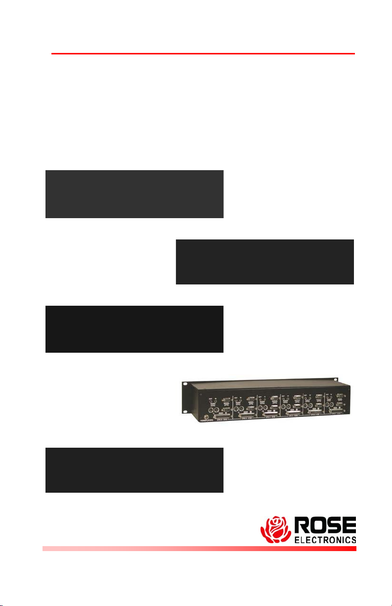
CrystalView Rack
TM
Installation and Operations
Model CRV-6SLP
Model CRV-6SLP/AUD
Model CRV-6DLP
Model CRV-6DLP/AUD
Model CRV-12SLP
Manual Supplement
PC-Single 6-port
PC-Single Serial/Audio
PC-Dual 6-port
PC Dual Serial/Audio
PC-Single 12-port
10707 Stancliff Road Phone: (281) 933-7673
Houston, Texas 77099 WWW.ROSE.COM
Page 2

Features
Extend six or twelve KVM stations from the CPUs using a single
CAT-5 twisted pair, solid core cable. (Up to 1,000 feet)
Available in PC single and dual models with opti ona l S erial /A udio
Package contents
The package contents consist of the following:
The CrystalView Local Rackmount Unit
The Installation and operations manual is included
with Remote unit shipments only. Additional manuals
are available on our web site at www.rose.com
Installation supplement
Optional power adapter (Auto-switching transformer)
A remote CrystalView unit is needed for each local CrystalView used.
Cables are usually ordered separately. If the package contents are not
correct, contact Rose Electronics or your reseller, so the problem can
be quickly resolved.
About this supplement
This supplement covers the installation of the CrystalView PC, Multiunit Rackmount model. Refer to the CrystalView installation and
operations manual for additional information and the warranty
statement.
Copyright Rose Electronics 1990-2002. All rights reserved.
No part of this manual may be reproduced, stored in a retrieval system, or transcribed in any form or
any means, electronic or mechanical, including photocopying and recording, without the prior written
permission of Rose Electronics.
Rose Electronics Part # MAN-SUPP-CRVRK
Printed In the United States of America - Revision 2.5
Page 3
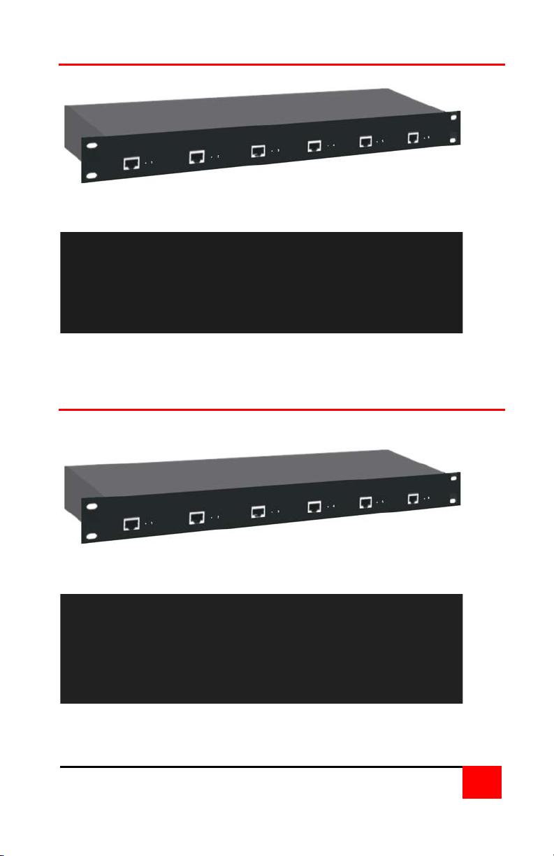
PC - 6 Unit model (Serial/Audio)
Front Panel
6-RJ45 – CAT-5 cable connection
Rear Panel
6-DB25F – CPU / KVM connections
6-DB9F Serial cable connections
Front Panel
6-RJ45 – CAT-5 cable connection
Rear Panel
6-DB25F – CPU / KVM connections
12-3.5mm stereo audio jacks (Audio in/out)
PC - 6 Unit model
1
Page 4

PC - 6 Unit Dual model
Front panel
6-RJ45 – CAT-5 cable connection
Rear panel
6-DB25 – CPU/KVM connections 6-DB9 serial connectors
6-HD15 monitor
Front Panel
6-RJ45 – CAT-5 cable connection
Rear panel
6-DB25F – CPU / KVM connections 12-MiniDin6 KBD/Mouse
6-HD15 Monitor
PC - 6 Unit Dual model with serial/ / audio
12-MiniDin6 KBD/Mouse 12-3.5mm audio in/out
2
Page 5
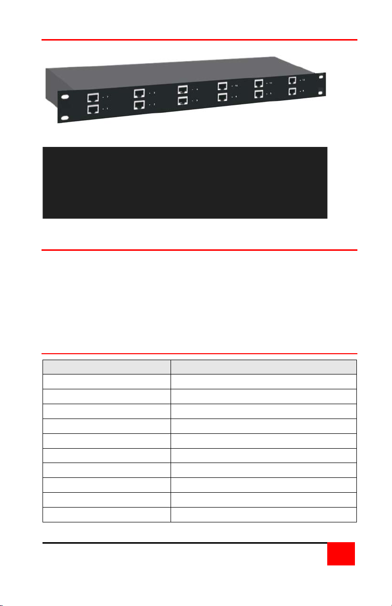
PC - 12 Unit model
Front Panel
12-RJ45 – CAT-5 cable connection
Rear Panel
12-DB25F – CPU / KVM connections
Part Number
Description
CRV-6SLP/AUD
6-Single Local CrystalViews w/audio
CRV-6SLP
6-Single Local CrystalViews
CRV-6DLP
6-Dual Local CrystalViews
CRV-6DLP/AUD
6-Dual local CrystalViews w/audio
CRV-12SLP
12-Single Local CrystalViews
CAB-08UTPnnn*
CAT-5 UTP cable
CAB-CXV66MMnnn*
Local to CPU cable
CAB-SPMMnnn*
3.5mm stereo audio cable
CAB-D9MFnnn*
CPU to Local serial input cable
TFR-05D400FSUP
Optional external power supply
Installation
Please refer to the installation procedures in the CrystalView manual
for your model. A detailed installation procedure for your model is
outlined in the CrystalView manual. A remote unit is needed for each
module used. The cable length jumpers on the remote unit must be set
for each unit according to the jumper-setting table in the manual. For
CAT5 cable distances less than 150 feet, the CrystalView MINI remote
unit can be used.
Part number and description table
* nnn = cable length in feet
3
Page 6
Remote
Stations
Local
CPUs
Remote
Stations
Local
CPUs
Remote
Units
KVM
Station
Remote
Units
KVM
Station
Standalone
CPU
Standalone
CPU
KVM
Switch
KVM
Units
KVM
KVM
Switch
1 of 8
KVM
Switch
1 of 8
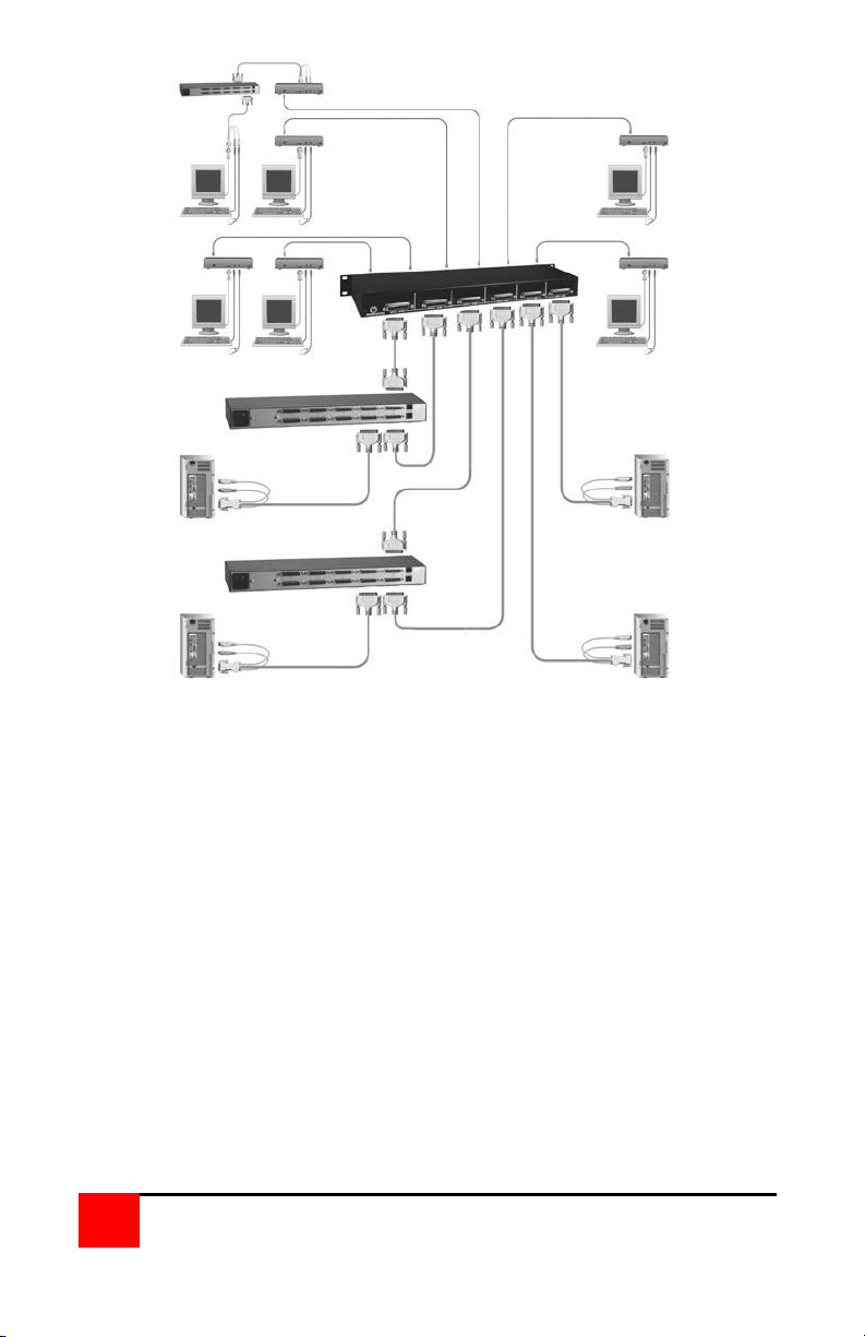
The above diagram shows the versatility of the CrystalView CAT5 rack.
The CrystalView CAT5 Rack can connect to standalone computers or
KVM switches using the appropriate cables. KVM stations connected
to a CrystalView remote unit can be up to 1000 feet (150 feet using a
CrystalView MINI remote unit) from the CrystalView CAT5 rack. A
remote CrystalView unit is needed for each module used in the
CrystalView CAT5 rack.
Any of the CrystalView CAT5 rack models can use the same type of
connections shown above. The serial/audio model can take advantage
of routing the remote CPUs serial and audio data to the local KVM
station.
4
Page 7
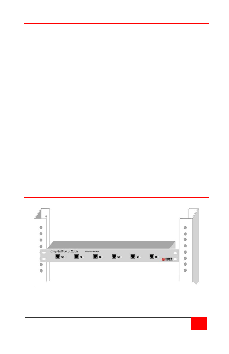
Rack mount instructions
To rack mount your CrystalView, attach the two rack mounting brackets
on your Unit to the rack using the appropriate size bolts, nuts and lock
washers.
The following guidelines should be observed when installing.
a). Do not exceed the operating temperature of 0
b). Do not block power supply vents or restrict airflow.
c). Mechanical loading of the rack should be considered to prevent
instability and possible tipping over.
d). Tighten all connectors securely and provide adequate strain relief
for all cables.
e). Provide a grounded power source to all Units. Pay special
attention to overall branch circuit load ratings before connecting
equipment to this source. Overloaded circuits are potential fire
hazards and can cause equipment failures or poor performance.
ο
C to 45
ο
C.
Rack mount illustration
5
Page 8
10707 Stancliff Road Phone: (281) 933-7673
Houston, Texas 77099 WWW.ROSE.COM
 Loading...