

Page 1
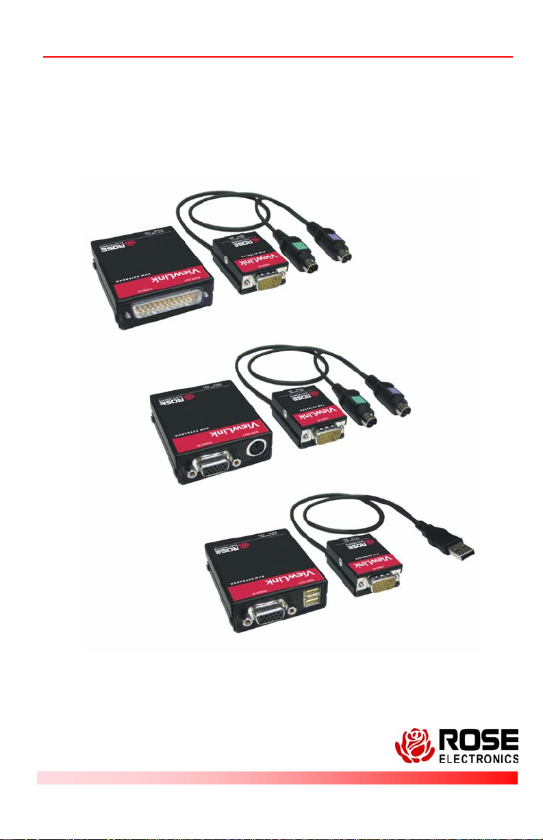
ViewLink CATx KVM Extender
INSTALLATION AND OPERATIONS
MANUAL
10707 Stancliff Road Phone: (281) 933-7673
Houston, Texas www.rose.com
Page 2

LIMITED WARRANTY
Rose Electronics® warrants the ViewLink™ CATx to be in good working order for one year from the
date of purchase from Rose Electronics or an authorized dealer. Should this product fail to be in good
working order at any time during this one-year warranty period, Rose Electronics will, at its option, repair
or replace the Unit as set forth below. Repair parts and replacement units will be either reconditioned or
new. All replaced parts become the property of Rose Electronics. This limited warranty does not include
service to repair damage to the Unit resulting from accident, disaster, abuse, or unauthorized
modification of the Unit, including static disch ar ge and power surges.
Limited Warranty service may be obtained by delivering this unit during the one-year warranty period to
Rose Electronics or an authorized repair cent er pr oviding a proof of purchase date. If this Unit is
delivered by mail, you agree to insure the Unit or assume the risk of loss or damage in transit, to prepay
shipping charges to the warranty service location, and to use the original shipping container or its
equivalent. You must call for a return authorization number first. Under no circumstances will a unit be
accepted without a return authorization number. Contact an authorized repair center or Rose
Electronics for further information.
ALL EXPRESS AND IMPLIED WARRANTIES FOR THIS PRODUCT INCLUDING THE WARRANTIES
OF MERCHANTABILITY AND FITNESS FOR A PARTICULAR PURPOSE, ARE LIMITED IN
DURATION TO A PERIOD OF ONE YEAR FROM THE DATE OF PURCHASE, AND NO
WARRANTIES, WHETHER EXPRESS OR IMPLIED, WILL APPLY AFTER THIS PERIOD. SOME
STATES DO NOT ALLOW LIMITATIONS ON HOW LONG AN IMPLIED WARRANTY LASTS, SO THE
ABOVE LIMITATION MAY NOT APPLY TO YOU.
IF THIS PRODUCT IS NOT IN GOOD WORKING ORDER AS WARRANTIED ABOVE, YOUR SOLE
REMEDY SHALL BE REPLACEMENT OR REPAIR AS PROVIDED ABOVE. IN NO EVENT WILL
ROSE ELECTRONICS BE LIABLE TO YOU FOR ANY DAMAGES INCLUDING ANY LOST PROFITS,
LOST SAVINGS OR OTHER INCIDENTAL OR CONSEQUENTI AL DAMAGES ARISING OUT OF THE
USE OF OR THE INABILITY TO USE SUCH PRODUCT, EVEN IF ROSE ELECTRONICS OR AN
AUTHORIZED DEALER HAS BEEN ADVISED OF THE POSSIBILITY OF SUCH DAMAGES, OR FOR
ANY CLAIM BY ANY OTHER PARTY.
SOME STATES DO NOT ALLOW THE EXCLUSION OR LIMITATION OF INCI DENTAL OR
CONSEQUENTIAL DAMAGES FOR CONSUMER PRODUCTS, SO THE ABOVE MAY NOT APPLY
TO YOU. THIS WARRANTY GIVES YOU SPECIFIC LEGAL RIGHTS AND YOU MAY ALSO HAVE
OTHER RIGHTS WHICH MAY VARY FROM STATE TO STATE.
IBM, AT, and PS/2 are trademarks of International Business Machines Corp. Microsoft and Microsoft
Windows are registered trademarks of Microsoft Corp. Any other trademarks mentioned in this manual
are acknowledged to be the property of the trademark owner.
Copyright Rose Electronics 2006. All rights reserved.
No part of this manual may be reproduced, stored in a retrieval system, or transcribed in any form or any
means, electronic or mechanical, including photocopying and recording, without the prior written permission of
Rose Electronics.
Rose Electronics Part # MAN-VLC5
Printed In the United States of America - Revision 1.0
Page 3

IC STATEMENTS, EU DECLARATION OF CONFORMITY
EUROPEAN UNION DECLARATION OF CONFORMITY
ACCORDING TO COUNCIL DIRECTIVE 89/336EEC & 73/23EEC
This equipment complies with the
requirements of the European EMC Directive
89/336/EEC
Page 4

TABLE OF CONTENTS
Contents
Quick Start guide..............................................................................................1
Disclaimer.........................................................................................................2
System introduction..........................................................................................2
Features............................................................................................................3
Package contents.............................................................................................3
Models ..............................................................................................................4
Installation.........................................................................................................5
Operation..........................................................................................................6
Keyboard Commands.......................................................................................6
Flash Utility features / procedure......................................................................8
TroubleShooting .............................................................................................11
Maintenance and Repair.................................................................................12
Technical Support...........................................................................................12
Safety..............................................................................................................13
Figures
Figure 1. Quick Installation Diagram ................................................................1
Figure 2. Models............................................................................................... 4
Figure 3. Monitor mounting bracket..................................................................5
Figure 4. Flash Scan Screen............................................................................9
Figure 5. Flash Port Configuration....................................................................9
Figure 6. Flash scan.......................................................................................10
Figure 7. Firmware update screen..................................................................10
Appendices
Appendix A – Part Numbers...........................................................................14
Appendix B - Specifications............................................................................15
Page 5
QUICK START GUIDE
Quick Start guide
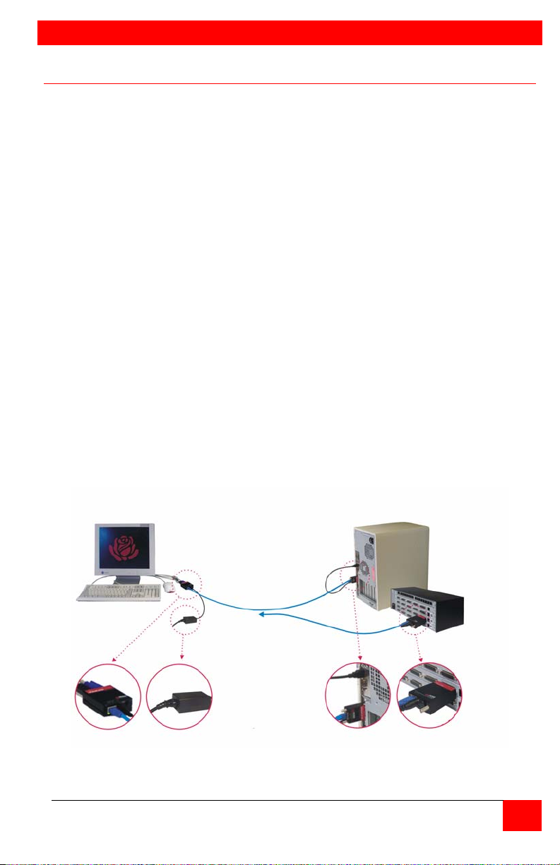
The ViewLink system consists of a transmitter unit that connects to the video,
keyboard, and mouse ports on a PC, server, or to a KVM switch and a
receiver unit connects to a keyboard, monitor, and mouse. The transmitter
and receiver units are connected together with up to 1,000 feet of standard
CATx cable. The transmitter and receiver are available for PS/2, USB, or
PS?-USB systems. This section briefly describes the installation procedures.
Refer to the following steps and diagram to install your ViewLink Catx.
Step #1 –Connect the Receiver unit to the keyboard, monitor, and mouse
cables on your KVM station. Connect the provided power adapter
to the Receiver unit’s power input jack.
Step #2 –Connect the Transmitter unit to the keyboard, monitor, and mouse
ports on your PC. Depending on your ViewLink CATx model,
connect it to either the PS/2 (MiniDin6) or USB ports. If you are
connecting to a KVM switch using the DB25 model, connect it to the
KVM port on the switch.
Step #3 –Connect the Receiver and Transmitter units together using up to
1,000 feet of CATx cable (CAT5, 5e, or 6).
Step #4 –Apply power to the KVM monitor, the Receiver unit, and boot your
PC (turn on the KVM switch if using the DB25 model).
When you initialize the extender, it automatically senses the cable distance
between the transmitter and receiver unit, adjusts the compensation and sets
up everything for you. Refer to the manual instructions for additional
information.
#1 Connect Receiver #2 Connect Transmitter
#3 Connect CATx Cable
KVM Station
#4 Apply power
Figure 1. Quick Installation Diagram
ViewLink CATX INSTALLATION AND OPERATIONS MANUAL
PC
or
Switch
1
Page 6

INTRODUCTION
Disclaimer
While every precaution has been taken in the preparation of this manual, the
manufacturer assumes no responsibility for errors or omissions. Neither does
the manufacturer assume any liability for damages resulting from the use of
the information contained herein. The manufacturer reserves the right to
change the specifications, functions, or circuitry of the product without notice.
The manufacturer cannot accept liability for damages due to misuse of the
product or other circumstances outside the manufacturer’s control. The
manufacturer will not be responsible for any loss, damage, or injury arising
directly or indirectly from the use of this product.
System introduction
Thank you for choosing the Rose Electronics ViewLink CATx enhanced
KVM extender. The ViewLink CATx is the result of Rose Electronics
commitment to providing state-of-the-art solutions for today’s demanding
workplace. The ViewLink CATx has proven to be a valuable investment for
any business, big or small, that has a need to access computers, servers, or
KVM switches from remote locations. Using the ViewLink CATx to remotely
access your computer has several applications that make it convenient for the
users. You can locate your computers in a secure area and access them
from other unsecured areas. Computers used in hazardous industrial
environments can be accessed remotely, keeping the users safe and
unexposed to any hazards.
The ViewLink CATx system consists of two Units, a transmitter Unit and a
receiver Unit. The transmitter connects easily to your computer or KVM
switch. The receiver Unit connects to a remote keyboard, video monitor and a
mouse. The transmitter and receiver units are connected together with
industry standard CAT5, CAT5e, or CAT6 shielded or unshielded, solid core
twisted-pair cable terminated with RJ45M connectors. All models can extend
the distance from the CPU up to 1,000 feet. Applications can be executed;
computer maintenance and any function normally done can be performed with
virtually no degradation in video quality and performance.
Installation only takes a few minutes since the ViewLink CATx automatically
sets up various parameters and functions based on your system topology.
There are no jumpers to set or adjustment knobs to turn. Parameters like
video gain are automatically compensated for and properly adjusted based o n
the length of Catx cable used. Some fine tuning can easily be done using
keyboard commands, but are rarely needed.
The only cable needed is a CATx cable to connect the transmitter to the
receiver. CATx cable can be ordered from Rose Electronics in 25-1,000 foot
lengths.
2
ViewLink CATX INSTALLATION AND OPERATIONS MANUAL
Page 7

Features
Available in models to connect to computers with PS/2 keyboard and
mouse ports, computers with USB keyboard and mouse ports, or KVM
switches with DB25F KVM ports
Extend a KVM station from a CPU using a single CATx cable
Resolution : 1600 x 1200 (up to 200 feet, 60m)
1280 x 1024 (up to 300 feet, 90m)
1024 x 768 (up to1000 feet, 300m)
ViewLink CATx uses a microprocessor to emulate the keyboard and
mouse for plug and play operation. The keyboard and mouse on the
receiver Unit do not have to be connected for the PC to boot; only the
transmitter Unit must be connected to the PC
Compatible with Rose Electronics family of KVM switches such as
ServeView Pro, UltraView Pro and UltraMatrix
Operating system independent
Status indicator LEDs on each RJ45 connector
All settings and video tuning are performed automatically. No user
adjustments are needed to achieve a crystal clear display on the receiver
KVM monitor. (Manual adjustments are available using special keyboard
commands)
Package contents
The package contents consist of the following:
The ViewLink CATx transmitter and receiver units as ordered
Power adapter for receiver Unit
Installation and operations manual
CATx and other cables are usually ordered separately. If the package
contents are not correct, contact Rose Electronics or your reseller, so the
problem can be quickly resolved.
Rose Electronics web site
Visit out web site at www.rose.com for additional information on the ViewLink
CATx and other products that are designed for data center applications,
classroom environments and other applications.
About this manual
This manual covers the installation and operation of the ViewLink CATx
models.
VIEWLINK CATX INSTALLATION AND OPERATIONS MANUAL
3
Page 8
MODELS
Models
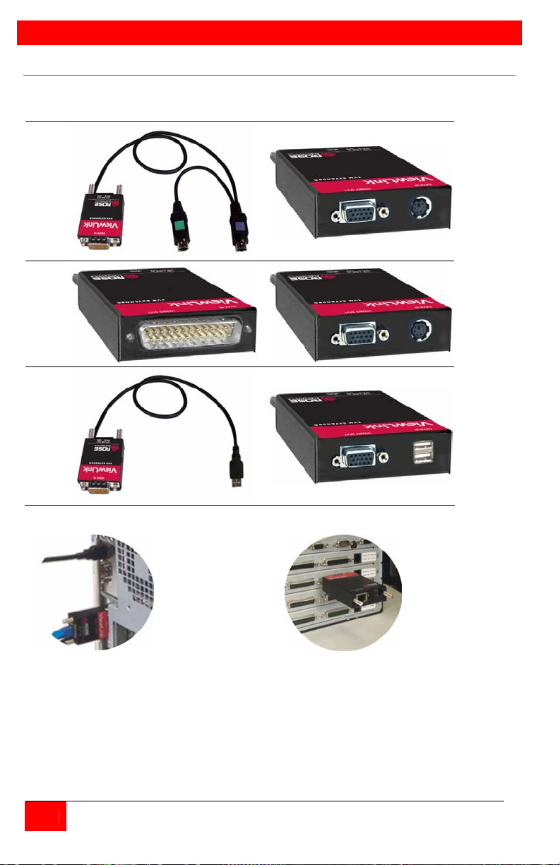
Transmitters Receivers
PS/2
DB25
USB
Transmitter with 2-PS/2 cables and 1-USB cable is also available
The PC model
connects directly
to the keyboard,
monitor and
mouse ports on
a PC
The DB25
model
connects
directly to the
KVM port of a
KVM switch
Figure 2. Models
The only cable needed to install the basic configuration of the ViewLink CATx is the
CATx cable that connects the transmitter to the receiver. Care should be used when
routing the CATx cable. Avoid routing the cable close to machinery or electronic
equipment. The electro-mechanical emissions may cause interference and
undesirable video performance.
4
ViewLink CATX INSTALLATION AND OPERATIONS MANUAL
Page 9
INSTALLATION
Installation
Installing the ViewLink CATx is a very easy plug-and-play process. For the PC, PS/2
and USB models simply connect the HD15M connector on the transmitter to the
HD15F video out connector on the PC. Connect the PS/2 or USB keyboard and
mouse cables to the corresponding connector ports on the PC. Connect the receiver
directly to the keyboard, monitor, and mouse cables used for the KVM station.
Connect the power adapter to the receiver unit’s power port. Finally, connect the
transmitter’s RJ45 connector to the receiver’s RJ45 connector using up to 1,000 feet of
CATx cable.
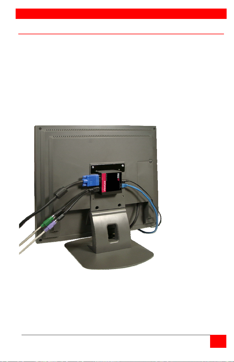
If you are using a flat panel monitor, Rose Electronics has designed a universal
mounting bracket that can be attached to any edge of a receiver unit and secured to
the back of a flat panel monitor. An example of using this bracket is shown below.
The bracket can be mounted vertically (as shown) or horizontally.
Figure 3. Monitor mounting bracket
For the Switch DB25 model, connect the transmitter’s DB25M connector to a KVM
switch’s DB25F KVM input connector. Connect the receiver directly to the keyboard,
monitor, and mouse cables used for the KVM station. Connect the power adapter to
the receiver unit’s power port. Finally, connect the Transmitter’s RJ45 connector to
the receiver’s RJ45 connector using up to 1,000 feet of CATx cable.
NOTE: Distance will vary depending on resolution used
VIEWLINK CATX INSTALLATION AND OPERATIONS MANUAL
5
Page 10

No user adjustments are needed. The ViewLink CATx will automatically
determine the CATx cable length between the transmitter and receiver and
automatically adjust the gain to compensate for the calculated cable length. If
needed, keyboard commands can be issued to fine tune the video gain and
equalization.
Apply power to the receiver unit, KVM monitor, and boot the PC. The monitor
connected to the receiver unit will display a clear, clean image of the boot
sequence.
Operation
Operation of your system is no different than having your keyboard, monitor, and
mouse connected directly to a PC or KVM switch. The only difference is they
can be up to 1,000 feet away. You can operate your system normally, programs
can be executed, maintenance can be performed, and any operation normally
performed can be done with no derogation in video quality and performance.
Keyboard Commands
Command Description
Left Ctrl, Left Shift, e: Perform a cable length measurement
Left Ctrl, Left Shift,
keyboard +:
Left Ctrl, Left Shift,
keyboard -:
Left Ctrl, Left Shift,
keypad +:
Left Ctrl, Left Shift,
keypad -:
Left Ctrl, Left Shift, k Saves any changes made
Left Ctrl, Left Shift, i*
(See * Below)
Left Ctrl, Left Shift, g*
(See * Below)
* CAUTION: DO NOT EXECUTE THESE COMMANDS WITHOUT A
TEXT EDITOR ACTIVE. A text editor such as notepad must be started and
selected prior to executing these keyboard commands.
Increase the video gain by 1
Decrease the video gain by 1.
increase the video equalization by 1
Decrease the video equalization by 1
Sends Transmitter, CPLD, and receiver firmware version to a
text editor on the CPU the unit is connected. Firmware is
reported as follows:
Transmitter = hxxy,
CPLD = yx,
Receiver = dxxy:
Where x is a decimal digit, and y is an alphabetic character
Send the most recent gain, equalization, cable length, autotdr
status, red, green, and blue skew values to a text editor.
6
ViewLink CATX INSTALLATION AND OPERATIONS MANUAL
Page 11

Keyboard Commands - Country Codes
The following country code table allows you to enter the country code for type of
keyboard and operating system used. This function is only required if your
operating system is country specific and requires that a keyboard map specific for
your operating system be entered. Sun Japanese keyboards and others that
require this should enter their country code.
To enter the country code, enter the following key sequence:
Lctrl, Lshift, l, x, Enter, (non-cap L, x)
or
Lctrl, Lshift, l, x, y, Enter,
where X and Y are keyboard numeric keys.
If the country code number is a single digit (0-9), enter one digit (or two digits,
ie.06), followed by enter. If the country code is a double digit (10-35), enter both
numbers, followed by enter. Each key is pressed and released, and no more than
2 seconds can elapse between any two keys of the sequence, or the command will
abort. The command only has to be entered once. ServSwitch™ Brand Mini
CAT5 KVM Extender saves the value in flash. The entered value does not change
if the unit is flashed with new code.
Code Country Code Country
00 Not Supported 18 Netherlands/Dutch
01 Arabic 19 Norwegian
02 Belgian 20 Persian (Farsi)
03 Canadian-Bilingual 21 Poland
04 Canadian-French 22 Portuguese
05 Czech Republic 23 Russia
06 Danish 24 Slovakia
07 Finnish 25 Spanish
08 French 26 Swedish
09 German 27 Swiss/French
10 Greek 28 Swiss/German
11 Hebrew 29 Switzerland
12 Hungary 30 Taiwan
13 International (ISO) 31 Turkish-Q
14 Italian 32 UK
15 Japan (Katakana) 33 US
16 Korean 34 Yugoslavia
17 Latin American 35 Turkish-F
36-255 Reserved
VIEWLINK CATX INSTALLATION AND OPERATIONS MANUAL
7
Page 12

FLASH PROCEDURE
Flash Utility features / procedure
The ViewLink Catx was designed to easily keep up with the ever changing
electronic world. The flash feature of the ViewLink CATx means the product
will always be up to date with new technologies, features, and enhancements.
Updating the flash memory is an easy process using Rose’s flash utility. The
universal flash utility is easily installed and can be used on a variety of Rose
products. When executed, the flash program will automatically detect the
product type to flash, validate the connections, and verify the product
firmware version.
To flash update the ViewLink CATx firmware you will need the flash utility
program and the firmware update file. The flash utility and current firmware
file for the ViewLink CATx can be downloaded from our web site at
www.rose.com/htm/download.htm.
After downloading the flash utility program and the firmware update file,
execute the program “SetupRoseKVMUtil-x_xx.exe” (x_xx = version level)
to install the flash utility program. Installation and set-up follow the standard
Windows
install the flash utility.
When installation of the flash utility is complete, connect the ViewLink CATx
receiver unit’s RJ45F (Link) connector to the serial port (Com1/DB9M) on the
PC the flash utility program was installed on using the flash utility cable
(RJ45M to DB9F cable, P/N CAB-ATRF). Connect the power adapter to the
ViewLink CATx receiver unit and apply power.
With all cable connections in place and the flash utility installed, execute the
flash program “…\Rose Electronics KVM Utility\KVMUtility.exe”. Depending
on the installation options chosen, you can execute the utility by clicking on
the Rose Electronics KVM Utility Icon from the desktop, Start Menu, or Quick
Start toolbar. The utility program, when executed, will automatically start
scanning for a connected supported Rose product (ViewLink CATx receiver).
The utility program will automatically start scanning COM1 and the PS/2 port
for a supported device. If a supported device is not found on COM1 or the
PS/2 port, the program will display the information shown in Figure 4 To exit,
press any key.
If the product has been connected to a port other than COM1, don’t exit the
utility program but modify the port to scan by clicking on “File” then “Scan for
Device On”. Next, click on the down arrow(s) to select a different COM port or
change the serial parameters as shown in Figure 5.
®
installation procedure. Follow the on-screen instructions to properly
8
ViewLink CATX INSTALLATION AND OPERATIONS MANUAL
Page 13
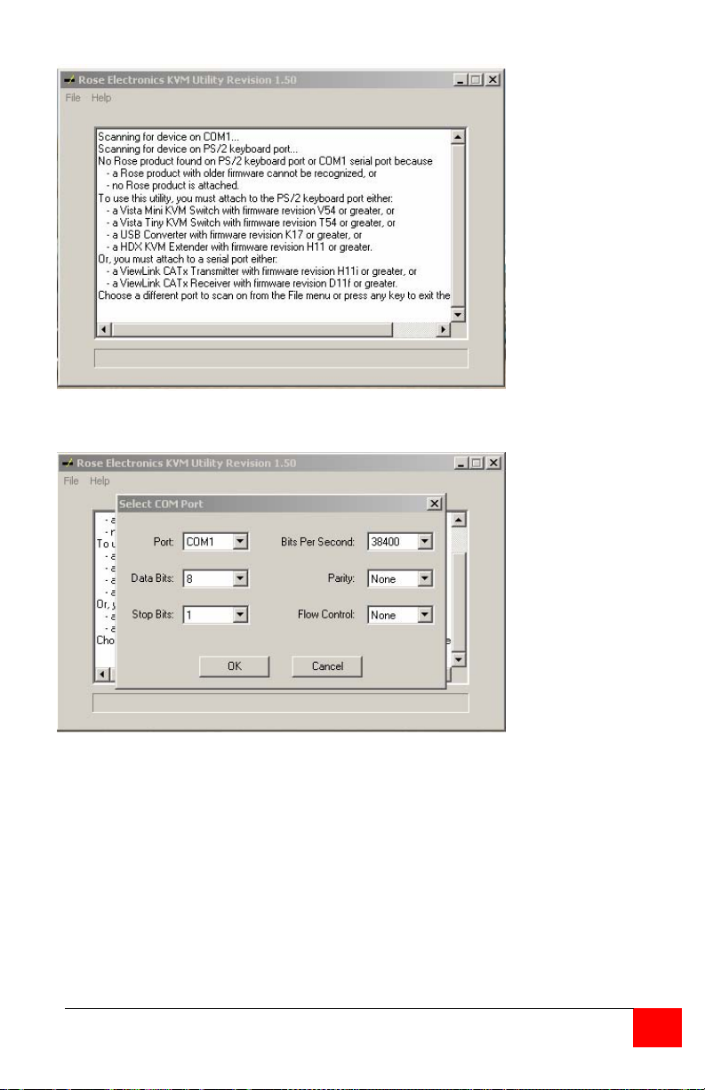
Figure 4. Flash Scan Screen
Figure 5. Flash Port Configuration
VIEWLINK CATX INSTALLATION AND OPERATIONS MANUAL
9
Page 14
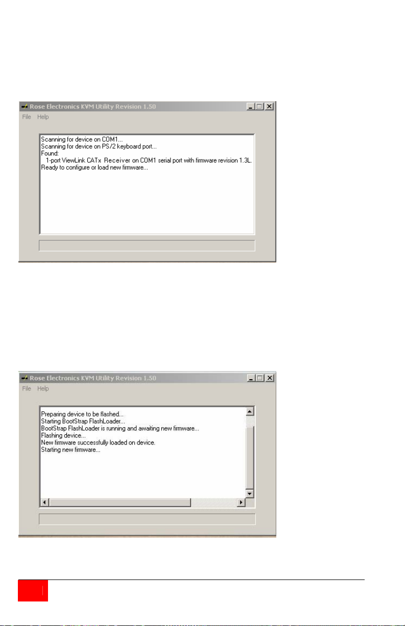
Upon successfully scanning and identifying a supported device, the detected
information shown in Figure 6 will display showing the product type and the
port it is connected to. The ViewLink CATx is ready to flash with the new
firmware.
Figure 6. Flash scan
To load the updated firmware to the ViewLink CATx, click on “File”, then
“Load New Firmware”. Select the downloaded firmware update file to load.
This will be a file with .hex file extension. Figure 7 show the flash update
screen which shows the progress and, when finished, the status of the flash
process. When the message “New firmware successfully loaded on device”
displays, the ViewLink CATx product is updated and ready to use with the
updated firmware.
Figure 7. Firmware update screen
Click on “Help” for additional information and examples.
10
ViewLink CATX INSTALLATION AND OPERATIONS MANUAL
Page 15

TROUBLESHOOTING
TroubleShooting
The troubleshooting section is used as a guide to understanding the
capabilities of the ViewLink CATx and for general troubleshooting. If you
have any problems or questions concerning the installation, operation or
usage of the ViewLink CATx that is not covered in this manual, please contact
Rose Electronics for technical support.
• No video on the receiver monitor
o Check CATx connection at the receiver, transmitter, patch panels (if
applicable)
o Check HD15 video connection at the receiver and transmitter
o Verify video is present at the video card output
• Keyboard has no effect
o Keyboard and mouse cables reversed at the PC
o Check keyboard cable connection at the Receiver
• Mouse erratic or not functioning
o Mouse and keyboard cables reversed at the PC
o Check mouse cable connection at the Receiver
• No video, keyboard or mouse functions
o Check all cable connection at the Receiver
o Check all cable connections at the Transmitter
o Check RJ45 connector LEDs. If the green and yellow LEDs are
alternately flashing, the firmware has become corrupt and the unit
must be flashed. This can occur if a power loss occurs during the
flash procedure.
VIEWLINK CATX INSTALLATION AND OPERATIONS MANUAL
11
Page 16

SERVICE and SUPPORT
Maintenance and Repair
This Unit does not contain any internal user-serviceable parts. In the event a
Unit needs repair or maintenance, you must first obtain a Return Authorization
(RA) number from Rose Electronics or an authorized repair center. This
Return Authorization number must appear on the outside of the shipping
container.
See Limited Warranty for more information.
When returning a Unit, it should be double-packed in the original container or
equivalent, insured and shipped to:
Rose Electronics
Attn: RA__________
10707 Stancliff Road
Houston, Texas 77099 USA
Technical Support
If you are experiencing problems, or need assistance in setting up,
configuring, or operating your CrystalView Plus, consult the appropriate
sections of this manual. If, however, you require additional information or
assistance, please contact the Rose Electronics Technical Support
Department at:
Phone: (281) 933-7673
E-Mail: [email protected]
Web: www.rose.com
Technical Support hours are from: 8:00 am to 6:00 pm CST (USA), Monday
through Friday.
Please report any malfunctions in the operation of this Unit or any
discrepancies in this manual to the Rose Electronics Technical Support
Department.
12
ViewLink CATX INSTALLATION AND OPERATIONS MANUAL
Page 17

SAFETY
Safety
The ViewLink CATx KVM extender has been tested for conformance to safety
regulations and requirements, and has been certified for international use.
Like all electronic equipment, the ViewLink CATx should be used with care.
To protect yourself from possible injury and to minimize the risk of damage to
the Unit, read and follow these safety instructions.
Follow all instructions and warnings marked on this Unit.
Except where explained in this manual, do not attempt to service this Unit
yourself.
Do not use this Unit near water.
Provide proper ventilation and air circulation.
Keep power cord and connection cables clear of obstr uctions that might
cause damage to them.
Use only power cords and connection cables designed for this Unit.
Use only a grounded (three-wire) electrical outlet.
Use only the power adapter provided with the ViewLink CATx.
Keep objects that might damage this Unit and liquids that may spill, clear
from this Unit. Liquids and foreign objects might come in contact with
voltage points that could create a risk of fire or electrical shock.
Operate this Unit only when the cover is in place.
Do not use liquid or aerosol cleaners to clean this Unit. Always unplug
this Unit from its electrical outlet before cleaning.
Unplug this Unit from the electrical outlet and refer servicing to a qualified
service center if any of the following conditions occur:
The power cord or connection cables are damaged or frayed.
The Unit has been exposed to any liquids.
The Unit does not operate normally when all operating instructions
have been followed.
The Unit has been dropped or the case has been damaged.
The Unit exhibits a distinct change in performance, indicating a need
for service.
VIEWLINK CATX INSTALLATION AND OPERATIONS MANUAL
13
Page 18

APPENDICES
Appendix A – Part Numbers
Transmitter P/N Description
VLT-MVP Single access, PS/2, VGA
VLT-MVU Single access, USB, VGA
VLT-MVB Single access, PS2 & USB, VGA
Receiver P/N Description
VLR-AVP Single access, PS/2, VGA
VLR-AVU Single access, USB, VGA
Kit P/N Description
VLK-TMVPRAVP Single access PS/2, VGA
VLK-TMVURAVU Single access USB, VGA
VLK-TMVBRAVP Single access, PS/2 & USB to PS/2, VGA
VLK-TMVBRAVU Single access, PS/2 & USB to USB, VGA
-W option = Auto Skew compensation
Cables Description
CAB-08C5UTPnnn CAT5 unshieded twisted pair
CAB-08C6UTPnnn CAT6 unshieded twisted pair
CAB-08C5STPnnn CAT5 shieded twisted pair
CAB-08C6STPnnn CAT6 shieded twisted pair
CAB-ATRFnnn DB9F to RJ45M flash utility cable
14
ViewLink CATX INSTALLATION AND OPERATIONS MANUAL
Page 19

Appendix B - Specifications
Dimensions Width Depth Height
Transmitter (in / cm)
Transmitter*(in / cm)
Receiver (in / cm) 2.2 / 56 2.56 / 65 0.83 / 21
* DB25 Transmitter model
Video:
Resolution: 1600 x 1200 (200 feet)
1280 x 1024 (300 feet)
1024 x 768 (300 – 1000 feet)
Compatibility: SVGA, VGA, XGA, RGB
Levels: 0.7V p-p
Sync type: Separate/composite TTL level
Support:
Keyboards: PS/2, USB
Video: VGA, SVGA, XGA, RGB
Mouse: PS/2 two button
Microsoft Compatible Mouse
Logitech Compatible Mouse
USB
Connectors:
PS/2 model: Video HD15F
Keyboard PS/2
Mouse PS/2
USB model: Video HD15F
Keyboard USB type A
Mouse USB type A
PS/2 & USB model has 2-PS/2 and 1-USB cable
Interconnect: CATx UTP/STP, EIA / (CAT5, 5e, 6) TIA 568
Power: Local From PC (Optional power adapter)
Remote + 5V 1.0A external
Environmental: Temp. 0°C – 45°C (32°F – 113°F)
Humidity 0% – 90% non-condensing
Approvals: CE
VIEWLINK CATX INSTALLATION AND OPERATIONS MANUAL
1.3 / 33
2.17 / 5.5
1.65 / 42
2.52 / 6.4
0.63 / 1.6
0.72 / 1.8
15
Page 20

10707 Stancliff Road Phone: (281) 933-7673
Houston, Texas 77099 WWW.ROSE.COM
 Loading...