

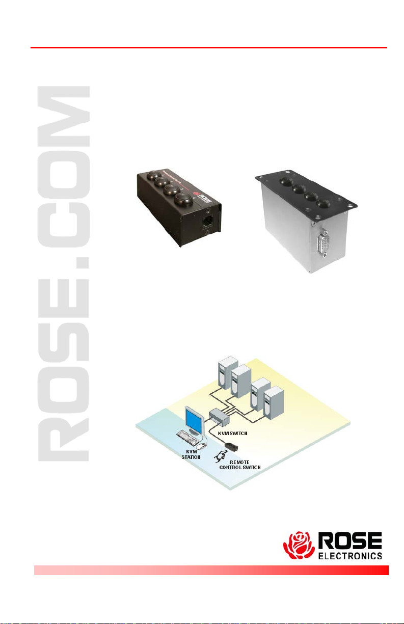
Remote Control Switch
Panel mount model
TYPICAL APPLICATION
INSTALLATION AND
OPERATIONS MANUAL
10707 Stancliff Road Phone: (281) 933-7673
Houston, Texas 77099 WWW.ROSE.COM


LIMITED WARRANTY
Rose Electronics® warrants the Remote Control Switch™ to be in good working order for one year
from the date of purchase from Rose Electronics or an authorized dealer. Should this product fail to
be in good working order at any time during this one-year warranty period, Rose Electronics will, at its
option, repair or replace the Unit as set forth below. Repair parts and replacement units will be either
reconditioned or new. All replaced parts become the property of Rose Electronics. This limited
warranty does not include service to repair damage to the Unit resulting from accident, disaster,
abuse, or unauthorized modification of the Unit, including static discharge and power surges.
Limited Warranty service may be obtained by delivering this unit during the one-year warranty period
to Rose Electronics or an authorized repair center providing a proof of purchase date. If this Unit is
delivered by mail, y ou agree to ins ure the Unit or assume the r isk of loss or damage in tra nsit, to
prepay shipping charges to the warranty service location, and to use the original ship ping con tainer or
its equivalent. You must call for a return authorization number first. Under no circumstances will a unit
be accepted without a return authorization number. Contact an authorized repair center or Rose
Electronics for further information.
ALL EXPRESS AND IMPLIED WARRANTIES FOR THIS PRODUCT INCLUDING THE
WARRANTIES OF MERCHANTABILITY AND FITNESS FOR A PARTICULAR P URPOS E, ARE
LIMITED IN DURATION TO A PERIOD OF ONE YEAR FROM THE DATE OF PURCHASE, AND NO
WARRANTIES, WHETHER EXPRESS OR IMPLIED, WILL APPLY AFTER THIS PERIOD. SOME
STATES DO NOT ALLO W LIMITATIONS ON HOW LONG AN IMPLIED WARRANTY LASTS, SO
THE ABOVE LIMITATION MAY NOT APPLY TO YOU.
IF THIS PRODUCT IS NOT IN GOOD WORKING ORDER AS WARRANTIED ABOVE, YOUR SOLE
REMEDY SHALL BE REPLACEMENT OR REPAIR AS PROVIDED ABOVE. IN NO EVENT WILL
ROSE ELECTRONICS BE LIABLE TO YOU FOR ANY DAMAGES INCLUDING ANY LOST
PROFITS, LOST SAVINGS OR OTHER INCIDENTAL OR CONSEQUENTIAL DAMAGES ARISING
OUT OF THE USE OF OR THE INABILITY TO USE SUCH PRODUCT, EVEN IF ROSE
ELECTRONICS OR AN AUTHORIZED DEALER HAS BEEN ADVIS ED OF THE POSSIBILITY OF
SUCH DAMAGES, OR FOR ANY CLAIM BY ANY OTHER PARTY.
SOME STATES DO NOT ALLOW THE EXCLUSION OR LIMITATION OF INCIDENTAL OR
CONSEQUENTIAL DAMAGES FOR CONSUMER PRODUCTS, SO THE ABOVE MAY NOT APPLY
TO YOU. THIS WARRANTY GIVES YOU SPECIFIC LEGAL RIGHTS AND YOU MAY ALSO HAVE
OTHER RIGHTS WHICH MAY VARY FROM STATE TO STATE.
IBM, AT, and PS/2 are tr ademarks of Internatio nal Business Machines Co rp. Micros oft and Micro s oft
Windows are registered trademarks of Microsoft Corp. Any other trademarks mentione d in this
manual are acknowledged to be the property of the trademark owner.
Copyright 2008 Rose Electronics. All rights reserved.
No part of this manual may be reproduced, stored in a retrieval system, or transcribed in any form or any
means, electronic or mechanical, including photocopying and recording, without the prior written permission
of Rose Electronics.
Rose Electronics Part # MAN-PRCS
Printed In the United States of America - Revision

System Introduction
Thank you for choosing the Rose Electronics Remote Control Switch for
your remote KVM switching application. The Remote Control Switch is the
results of Rose Electronics commitment to provide solid, practical switching
solutions for today's business world. The Remote Control Switch provides a
convenient way to switch to any KVM switches CPU port with the push of a
button.
The Remote Control Switch is easy to install and operate. Each button can
be programmed to switch the KVM station to any CPU port. You can
program button #1 to switch to CPU port 5, button #2 to switch to CPU port
10, etc. Programming the push buttons is easy and requires no software.
An example of programming button #2 to switch to CPU port #18 is:
1. Remove power from the RCS (disconnect serial cable)
2. Using a keyboard, connect the switch to CPU port # 18.
(Using Rose Electronics UltraMatrix, press and release the
left ctrl key, type in 18, press enter)
3. Hold down all buttons on the RCS
4. Apply power to the RCS, (reconnect serial cable)
then release all buttons
5. Within 3 seconds, press button #2.
6. Done, this configuration is saved in non volatile memory
Any time you press button #2, the KVM station will switch to CPU
port #18 and that computers video will display. Any button can be
programmed to switch to any CPU port.
If the RCS is not used with an external power supply, the KVM Switches
CPU card must first be modified. Only cards where the remote control
switch will be connected to will have to be modified. See Figure 1.
1. Remove the card to modify from the chassis.
2. Locate the 1K resistor R4. It is directly behind the RJ45 connector.
3. Replace R4 with a 10 Ohm, 1/4W, 5% resistor.
4. Install the card in the chassis and apply power.

Dimensions
Width
Depth
Height
Weight
5.0”
2.0”
1.0”
0.25 lbs
12.7
5.1
2.54 cm
0.11 kg
1- Remove securing screws from each end of the CPU
4- Reinstall the CPU card in the chassis and apply power
Resistor R4
card the RCS will be connected to
2- Carefully remove the card from the chassis backplane,
pull the card straight back
3- Locate 1K resistor R4 (directly behind the RJ45
connector) and replace the 1K resistor with a 10 Ohm,
1/4 watt, 5% resistor
Figure 1. Replacing Resistor R4
Specifications
Part numbers
RCS-2RS/xx 2-Port model
RCS-4RS/xx 4-Port model
Options: (/xx)
/RJ - RJ11F Serial Interface
/SW – External power adapter
• Serial Interface Options:
/RJ - RJ11F Serial Interface
/D9 - DB9M Serial Interface
• Panel Mount Option
/PMSR Panel Mount
/GCRA Color sequence - Green,
Clear, Red, Amber
Externally Powered
/SW Optional Power Supply
Part # TFR-05D200FSUP-3.5
Cables: CAB-06RJnnn RJ11 6-conductor Data Cable
Connectors Serial RJ11F / DB9
External power: 3.5mm on /SW Power Option
Indicators LED Port selection (in button)
Chassis Electro-galvanized steel, Black powder coated
Environmental 0° - 45°C / 32°F - 113°F, 5%-80% non-condensing RH

R
UMC 1x4
UMC 0x4
REMOTE CONTROL SWITCH
INSTALLATION AND PROGRAMMING
GUIDE
INSTALLATION
If the RCS is not used with an external power supply, the UltraMatrix UMC_x4 card must first be modified. Only cards where the remote control switch
will be connected to will have to be modified.
5. Remove the UMC 0x4 or UMC 1x4 card from the UltraMatrix
chassis.
6. Locate the 1K resistor R4. It is directly behind the RJ45 connector.
7. Replace R4 with a 10 Ohm, 1/4W, 5% resistor.
8. Install the UMC 0x4 or UMC 1x4 card in the UltraMatrix chassis and
apply power.
OR

9. Attach the DB9 connector of the CAB-ATRX cable to the mating
DB9 connector on the remote control switch. Attach the RJ12
connector of the CAB-ATRX cable to the RS232 RJ45 connector on
the UMC _x4 card in the UltraMatrix chassis.
10. UltraMatrix firmware must be MX25 or greater which is able to
accept 'kmc<1|2|3|4>s' serial commands.
11. UltraMatrix Serial Control Protocol must be set to ‘STANDARD’.
12. Press one of the CPU select buttons on the remote control switch to
connect to the corresponding computer. There is a slight delay
while the UltraMatix changes connection before the LED illuminates.
The LED indicates actual connection made whether it occurred by
the remote control switch, keyboard command, or by another user.
In the case where connection to a cpu not supported by any of the
buttons is made, all LEDs will be off.
PROGRAMMING
By default, RCS buttons 1 through 4 are programmed to select computers
connected to ports 1 through 4 on the UltraMatrix. This may be changed to
any valid ports on the UltraMatrix.
To program the RCS
1. Remove power to the RCS.
2. Using a keyboard, connect the UltraMatrix to the computer port that
is to be controlled by the RCS.
3. While holding down all four buttons apply power to the RCS.
4. Release all four buttons on the RCS.
5. Within 3 seconds, press the button on the RCS that will be used to
select the currently connected port.
6. The RCS will save assigned ports to non-volatile memory until
reprogrammed.

10707 Stancliff Road Phone: (281) 933-7673
Houston, Texas 77099 WWW.ROSE.COM
 Loading...