

Page 1
REMOTE CONTROL PANEL
INSTALLATION
AND
OPERATIONS MANUAL
10707 Stancliff Road Phone: (281) 933-7673
Houston, Texas 77099 WWW.ROSE.COM
Page 2

LIMITED WARRANTY
Rose Electronics® warrants the Remote Control Panel™ to be in good working order for one year from
the date of purchase from Rose Electronics or an authorized dealer. Should this product fail to be in
good working order at any time during this one-year warranty period, Rose Electronics will, at its
option, repair or replace the Unit as set forth below. Repair parts and replacement units will be either
reconditioned or new. All replaced parts become the property of Rose Electronic s . This lim ited
warranty does not include service to repair damage to the Unit resulting from accident, disaster, abuse,
or unauthorized modification of the Unit, including static discharge and power surges.
Limited Warranty service may be obtained by delivering this unit during the one-year warranty period to
Rose Electronics or an authorized repair center providing a proof of purchase date. If this Unit is
delivered by mail, you agree to insure the U nit or assume the risk of loss or dama ge in transit, to
prepay shipping charges to the warranty service location, and to use the original ship ping con tainer or
its equivalent. You must call for a return authorization number first. Under no circumstances will a unit
be accepted without a return authorization number. Contact an authorized repair center or Rose
Electronics for further information.
ALL EXPRESS AND IMPLIED WARRANTIES FOR THIS PRODUCT INCLUDING THE WARRA NTIE S
OF MERCHANTABILITY AND FITNESS FOR A PARTICULAR PURPOSE, ARE LIMITED IN
DURATION TO A PERIOD OF ONE YEAR FROM THE DATE OF PURCHASE, AND NO
WARRANTIES, WHETHER EXPRESS OR IMPLIED, WILL APPLY AFTER THIS PERIOD. SOME
STATES DO NOT ALLOW LIMITATIONS ON HOW LONG AN IMPLIED WARRANTY LASTS, SO
THE ABOVE LIMITATION MAY NOT APPLY TO YOU.
IF THIS PRODUCT IS NOT IN GOOD WORKING ORDER AS WARRANTIED ABOVE, YOUR SOLE
REMEDY SHALL BE REPLACEMENT OR REPAIR AS PROVIDED ABOVE. IN NO EVENT WILL
ROSE ELECTRONICS BE LIABLE TO YOU FOR ANY DAMAGES INCLUDING ANY LOST PROFITS,
LOST SAVINGS OR OTHER INCIDENTAL OR CONSEQUENTIAL DAMAGES ARISING OUT OF
THE USE OF OR THE INABILITY TO USE SUCH PRODUCT, EVEN IF ROSE ELECTRONICS OR
AN AUTHORIZED DEALER HAS BEEN ADVISED OF THE POSSIBILITY OF SUCH DAMAGES, OR
FOR ANY CLAIM BY ANY OTHER PARTY.
SOME STATES DO NOT ALLOW THE EXCLUSION OR LIMITATION OF INCIDENTAL OR
CONSEQUENTIAL DAMAGES FOR CONSUMER PRODUCTS, SO THE ABOVE MAY NOT APPLY
TO YOU. THIS WARRANTY GIVES YOU SPECIFIC LEGAL RIGHTS AND YOU MAY ALSO HAVE
OTHER RIGHTS WHICH MAY VARY FROM STATE TO STATE.
NOTE: This equipment has been t es ted and found to comply with the limits for a Cl ass A digital device,
pursuant to Part 15 of the FCC Rules. These limits are designed to provide re asonable protection
against harmful interference when the equipment is operated in a commer cial environment. This
equipment generates, uses, and can radiate radio frequency energy and, if not installed and used in
accordance with the instruction manual, may cause harmful int er feren ce to radio com mun ic ati on s.
Operation of this equipment in a residential area is likely to cause harmful interference in which case
the user will be required to correct the interference at his own expense.
IBM, AT, and PS/2 are t rademarks of I nternat io nal Business Machines Corp. Microsoft an d Microsoft
Windows are registered trademarks of Microsoft Corp . Any other trad e m ark s men tioned in this manu al
are acknowledged to be the property of the trademark owner.
Copyright 2004, Rose Electronics. All rights reserved.
No part of this manual may be reproduced, stored in a retrieval system, or transcribed in any form or any
means, electronic or mechanical, including photocopying and recording, without the prior written permission of
Rose Electronics.
Rose Electronics Part # MAN-RCP
Printed In the United States of America - Revision 1.0
Page 3

5
EUROPEAN UNION DECLARATION OF CONFORMITY
ACCORDING TO COUNCIL DIRECTIVE 89/336EEC & 73/23EEC
This equipment is in conformity with the
protection requirements of the following
Council Directives:
The Declaration of Conformity is based upon
compliance of the product with the following
harmonized standards:
EN55022: 1998 EN61000-4-5: 199
EN55024: 1998 EN61000-4-6: 1996
EN61000-4-2: 1995 EN61000-4-11: 1994
EN61000-4-3: 1995 EN60950: 2000
EN61000-4-4: 1995
Page 4

INTRODUCTION
Disclaimer
While every precaution has been taken in the preparation of this manual, the
manufacturer assumes no responsibility for errors or omissions. Neither
does the manufacturer assume any liability for damages resulting from the
use of the information contained herein. The manufacturer reserves the right
to change the specifications, functions, or circuitry of the product without
notice.
The manufacturer cannot accept liability for damages due to misuse of the
product or other circumstances outside the manufacturer’s control. The
manufacturer will not be responsible for any loss, damage, or injury arising
directly or indirectly from the use of this product.
System introduction
Thank you for choosing the Rose Electronics Remote Control Panel for
your remote KVM switching application. The Remote Control Panel is the
results of Rose Electronics commitment to provide solid, practical switching
solutions for today's business world. The Remote Control Panel connects
directly to the RS232 serial port on a KVM switch allowing you to remotely
switch to any CPU port.
The Remote Control Panel is easy to install and operate. No set-up is
required; just connect a Rose Electronics UltraView, ServeView, or
MultiVideo product to the Remote Control Panel with an RJ11 cable, apply
power and push the button. If you push button #5 on the Remote Control
Panel, the CPU connected to port 5 on the KVM switch will connect to the
KVM port and display on the KVM station.
Page 5

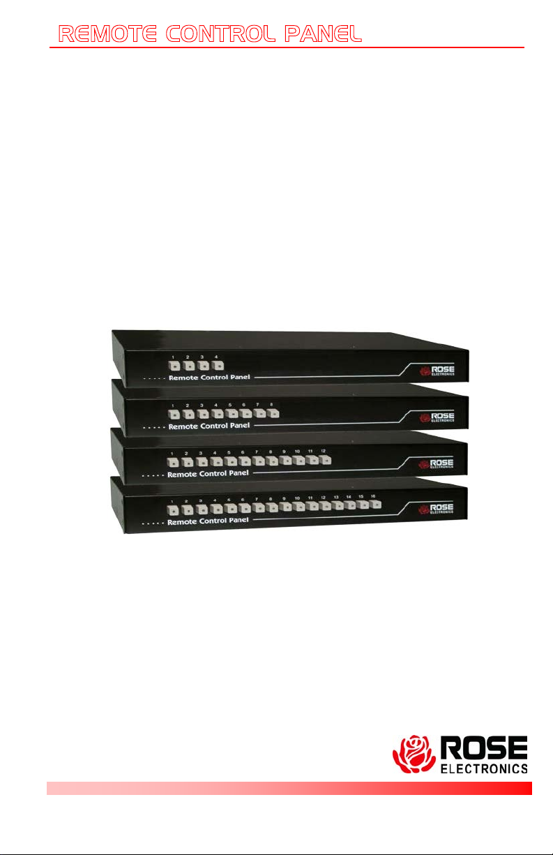
4-Button
8-Button
12-Button
16-Button
Rear View (All Models)
Models
Connectors – RS232
Power
Installation
The Remote Control Panel is easy to insta ll.
Connect a serial cable from your KVM switch’s RS232 port to the
Remote Control Panel’s rear RS232 port
Connect the power adapter to the unit
Connect the power adapter to 110/220 v source
It is ready to use. No setup or configuration is needed.
Page 6

Part numbers
Specifications
Cables
A serial adapter cable is used to connect the Remote Control Panel to the
RS232 port on a compatible KVM switch. The DB9M to RJ11 cable
connects from the DB9M connector on the Remote Control Panel to the
RS232 port on the KVM switch. Extended distance cables are offered for
distances greater than 5 feet from the Remote Control Panel.
Operation
Operating the Remote Control Panel is as easy as pushing a button. If you
want the KVM station to switch to CPU port 5, just push button #5.
Immediately the KVM station will switch to CPU port #5 and that computer’s
video will disp lay.
Model
RCP-16RS 16 switch model
RCP-12RS 12 switch model
RCP-8RS 8 switch model
RCP-4RS 4 switch model
ACC-ATRX Serial adapter, RJ11 to DB9F
CAB-04RJnnn RJ11 cable
(nnn = length in feet)
RM-UL19 19” Rack mount kit
RM-UL23 23” Rack mount kit
RM-UL24 24” Rack mount kit
Width Depth Height Weight
Dimensions 13.2 4.5 1.75 in 4lbs
33.5 11.4 4.45 cm 1.8kg
Connectors RS232 - DB9M
Power - DIN5 Indicators
Indicators CPU port selection LED
Chassis Electro galvanized steel,
black powder coated
Temp 0° – 45°C / 32°F – 113°F
Humidity 5% – 80% non-condensing RH
Approvals CE
Page 7

Page 8

10707 Stancliff Road Houston, Texas 77099
Phone: (281) 933-7673 Internet: WWW.ROSE.COM
 Loading...