

Porter
Code activated switch
INSTALLATION
AND
OPERATIONS MANUAL
TM
10707 Stancliff Road Phone: (281) 933-7673
Houston, Texas 77099 WWW.ROSE.COM


Limited Warranty
Rose Electronics warrants the Porter™ to be in good working order for one year from the date
of purchase from Rose Electronics or an authorized dealer. Should this product fail to be in
good working order at any time during this one-year warranty period, Rose Electronics will, at
its option, repair or replace the Unit as set forth below. Repair parts and replacement units will
be either reconditioned or new. All replaced parts become the property of Rose Electronics.
This limited warranty does not include service to repair damage to the Unit resulting from
accident, disaster, abuse, or unauthorized modification of the Unit, including static discharge
and power surges.
Limited Warranty service may be obtained by delivering this unit during the one-year warranty
period to Rose Electronics or an authorized repair center providing a proof of purchase date. If
this Unit is delivered by mail, you agree to insure the Unit or assume the risk of loss or damage
in transit, to prepay shipping charges to the warranty service location, and to use the original
shipping container or its equivalent. You must call for a return authorization number first. Under
no circumstances will a unit be accepted without a return authorization number. Contact an
authorized repair center or Rose Electronics for further information.
ALL EXPRESS AND IMPLIED WARRANTIES FOR THIS PRODUCT INCLUDING THE
WARRANTIES OF MERCHANTABILITY AND FITNESS FOR A PARTICULAR PURPOSE, ARE
LIMITED IN DURATION TO A PERIOD OF ONE YEAR FROM THE DATE OF PURCHASE, AND
NO WARRANTIES, WHETHER EXPRESS OR IMPLIED, WILL APPLY AFTER THIS PERIOD.
SOME STATES DO NOT ALLOW LIMITATIONS ON HOW LONG AN IMPLIED WARRANTY
LASTS, SO THE ABOVE LIMITATION MAY NOT APPLY TO YOU.
IF THIS PRODUCT IS NOT IN GOOD WORKING ORDER AS WARRANTIED ABOVE, YOUR SOLE
REMEDY SHALL BE REPLACEMENT OR REPAIR AS PROVIDED ABOVE. IN NO EVENT WILL
ROSE ELECTRONICS BE LIABLE TO YOU FOR ANY DAMAGES INCLUDING ANY LOST
PROFITS, LOST SAVINGS OR OTHER INCIDENTAL OR CONSEQUENTIAL DAMAGES ARISING
OUT OF THE USE OF OR THE INABILITY TO USE SUCH PRODUCT, EVEN IF ROSE
ELECTRONICS OR AN AUTHORIZED DEALER HAS BEEN ADVISED OF THE POSSIBILITY OF
SUCH DAMAGES, OR FOR ANY CLAIM BY ANY OTHER PARTY.
SOME STATES DO NOT ALLOW THE EXCLUSION OR LIMITATION OF INCIDENTAL OR
CONSEQUENTIAL DAMAGES FOR CONSUMER PRODUCTS, SO THE ABOVE MAY NOT APPLY
TO YOU. THIS WARRANTY GIVES YOU SPECIFIC LEGAL RIGHTS AND YOU MAY ALSO HAVE
OTHER RIGHTS WHICH MAY VARY FROM STATE TO STATE.
NOTE: This equipment has been tested and found to comply with the limits for a Class A digital
device, pursuant to Part 15 of the FCC Rules. These limits are designed to provide reasonable
protection against harmful interference when the equipment is operated in a commercial
environment. This equipment generates, uses, and can radiate radio frequency energy and, if
not installed and used in accordance with the instruction manual, may cause harmful
interference to radio communications. Operation of this equipment in a residential area is likely
to cause harmful interference in which case the user will be required to correct the interference
at his own expense.
IBM, AT, and PS/2 are trademarks of International Business Machines Corp. Microsoft and
Microsoft Windows are registered trademarks of Microsoft Corp. Any other trademarks
mentioned in this manual are acknowledged to be the property of the trademark owner.
Copyright 1986-1991 Rose Electronics. All rights reserved.
No part of this manual may be reproduced, stored in a retrieval system, or transcribed in any form or
any means, electronic or mechanical, including photocopying and recording, without the prior written
permission of Rose Electronics.
Rose Electronics Part # MAN-PO
Printed In the United States of America - Revision 1.0

Table of Contents
Contents
Tables
Appendices
Introduction ........................................................................................................................ 1
Features ............................................................................................................................. 1
Model Number and Options ............................................................................................... 1
First Steps .......................................................................................................................... 2
Contents ........................................................................................................................ 2
Connecting the Cables ................................................................................................... 2
Configuring the Porter ................................................................................................... 2
Configuring your Computers .......................................................................................... 2
If You Have A Problem ................................................................................................... 2
Where to Go From Here ................................................................................................ 2
Front panel..................................................................................................................... 3
Rear panel (Serial model) ............................................................................................... 4
Rear panel (Parallel model) ............................................................................................ 5
Quick set-up ....................................................................................................................... 6
Serial Porter ................................................................................................................... 6
Parallel Porter ................................................................................................................ 7
Configuring Your PC ...................................................................................................... 7
Cable connection ........................................................................................................... 8
Configuration of Serial Units .......................................................................................... 9
Serial Configuration Menu Items ................................................................................... 9
Configuration of Parallel Units ..................................................................................... 13
Operating Modes ......................................................................................................... 16
Front Panel .................................................................................................................. 19
Porter Commands ............................................................................................................ 20
Applications ..................................................................................................................... 26
Diagnostic ........................................................................................................................ 27
Diagnostic Tests .......................................................................................................... 27
Reloading Factory Defaults .......................................................................................... 30
Maintenance and Repair .............................................................................................. 30
Table 1 Configuration Menu Display .................................................................................. 9
Table II LED Power up Display ......................................................................................... 14
Table III LED Error Display ................................................................................................ 15
Table IV LED Operation Display ....................................................................................... 19
Table V Diagnostics LED Display...................................................................................... 28
Table VI Diagnostic LED Error Display .............................................................................. 29
Table VII Loopback Test Connectors ................................................................................ 30
Appendix A – Porter Pin outs ........................................................................................... 31
Appendix B – Cable Pin out ............................................................................................. 33
Appendix C – Specifications ............................................................................................ 34

Introduction
1
Introduction
Features
Model Number and Options
PO-4S – 4 port serial
Serial models have 2 options:
This manual contains information for the installation and operation of the Porter, Rose
Electronics' name for its series of code activated switches. The Porter consists of a
switch unit and a separate wall mounted power adapter. You have chosen a versatile
microprocessor controlled switch that allows a computer to access serial devices such as
modems or instruments. The selection is through a code that is transmitted intermixed
with the normal data to the device. Since the Porter has buffer memory, each device may
simultaneously load data into the unit. The serial models allow different baud rates and
protocols to operate independently on each port with full duplex communications. All
equipment is connected by cables to the Porter's rear panel. The unit's external power
adapter connector and on/off switch are also n its rear panel. The Porter's front panel has
13 LEDs which display status information and switches which are used to manually
control the unit and run the unit's diagnostics.
One computer to many peripherals
Compatible with any computer – PCs, Macs, minis
Compatible with all printers and plotters
Simultaneous inputs from all computers
Up to 256K buffer
Serial (RS232) or parallel (Centronics)
Models for either four or eight devices
Advanced features for trouble-free performance
LEDs show data activity and status
Self-text and diagnostic features
Made in USA
The Porter is available in several models, 4 or 8 channels, serial or parallel, and with a 16K
base buffer (Expandable to 256K). The model numbers are:
PC-8S – 8 port serial
PO-4P – 4 port parallel
PO-8P – 8 port parallel
/B buffer options = 64K or 256K
PORTER INSTALLATION AND OPERATIONS MANUAL
1- RS422 type ports
2- Max baud rate of 38400
(All standard baud rates are doubled
with this option)

Getting Started
2
First Steps
Contents
Connecting the Cables
Configuring the Porter
Configuring your Computers
If You Have A Problem
Where to Go From Here
Congratulations! You have chosen one of the best code activated switches on the
market. The paragraphs below summarize the steps to integrate the Porter into your
environment.
You should have received the Porter system unit, a power adapter, and this Porter
installation and operations manual. If additional cables were ordered, they usually arrive
in the same package.
Cabling is one area you should pay careful attention to. Consult the cabling guides in this
manual for the correct pin outs. If you need assistance, contact our tech support, we will
be happy to assist you.
The Porter is a versatile unit. It can be configured to match the type of equipment that
you have. To configure the switch requires connecting a computer or terminal to the
configuration port on the porter – port 0.
If you have a PC, then you run a terminal emulation program to setup the Porter. The
parameters are saved in the Porter. From time to time as you change the configuration of
your equipment, you may need to adjust the configuration of the Porter. You do not have
to have a PC to use the switch or configure it.
The final step is to make sure that your computer's software is configured to access the
features of the Porter. This involves setting up the proper communication settings for
serial ports and providing a method to issue commands to the Porter. The commands
are typically issued from PCs by user software or from batch files. If you use serial ports
on PCs, it is required to setup the AUTOEXEC,BAT file with the proper DOS MODE
statements.
Well we certainly hope all goes well with your installation, but if there is a problem, we
are only a phone call away. If you have already installed the switch and something is not
right, it can be helpful to be at the switch location and at the computer connected to port
0 on the Porter when you call. The front panel of the Porter is very useful to diagnose
problems that can occur.
We would like to think that you would read the rest of this manual, it may not be the most
exciting reading material, but at least scan through it for the key points. Use it to get the
correct cabling information. Thank you for choosing Rose Electronics and the Porter.
PORTER INSTALLATION AND OPERATIONS MANUAL
MODELS
3
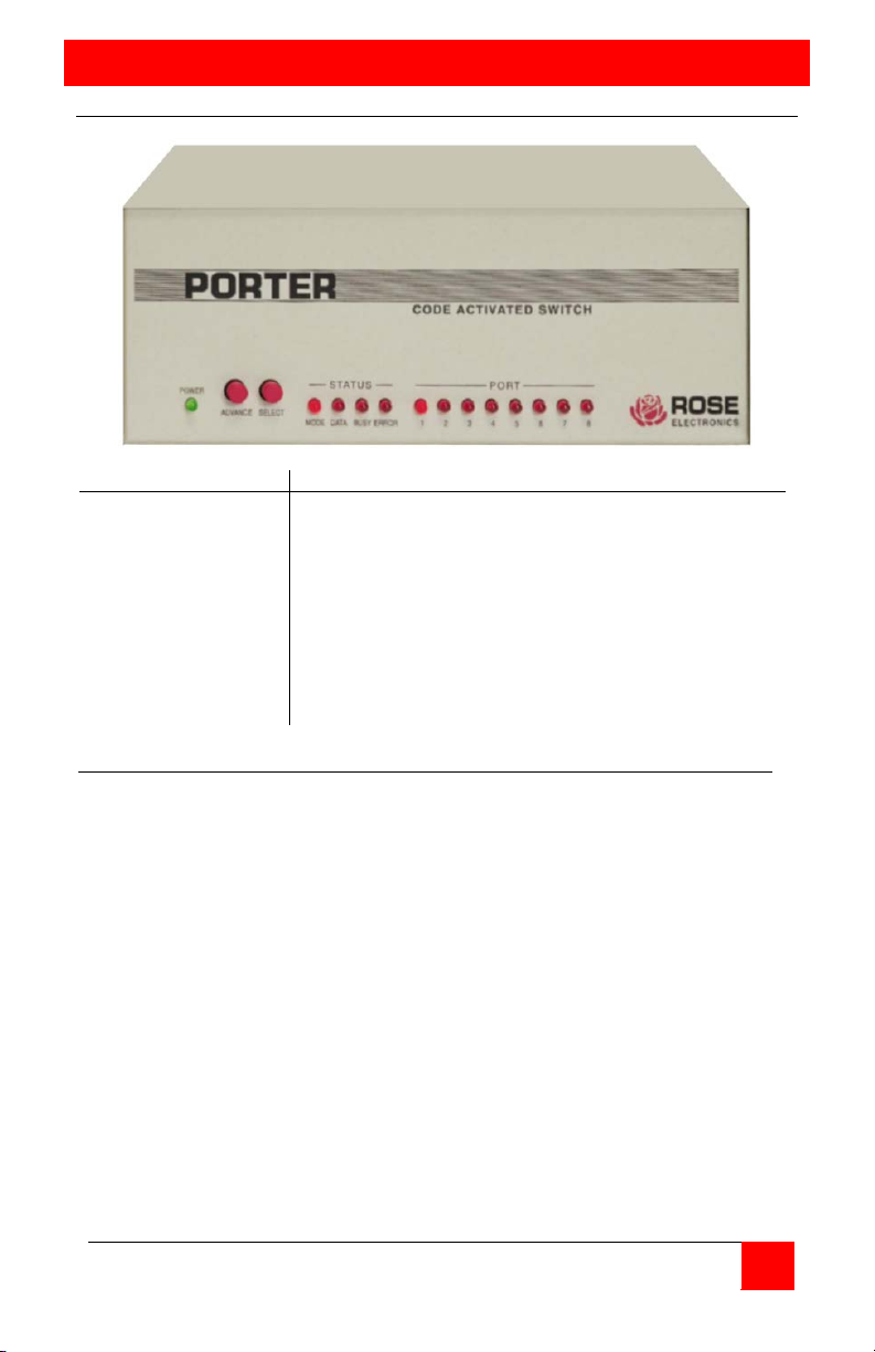
Front panel
Indicators
Description
Power
(1-8)
Green LED
On = active port
Buttons
Select
Select port
M D B E 1 2 3 4 5 6 7 8
ο ο ο
ο
•
ο ο ο ο ο ο ο
Note 1
ο ο ο
ο ο ο ο ο ο ο ο
ο
Note 2
ο ο ο
ο
• • • • • • •
•
Note 3
•
ο ο ο
x x x x x x x x
Note 4
• • •
ο ο ο ο ο ο ο ο
ο
Note 5
Note 1 ….. Unit operational, normal mode, connected to port 1
Note 2 ….. Unit operational, normal mode, null destination
Note 3 ….. Unit operational, broadcast mode, all ports selected
Note 4 ….. Unit in manual mode, displays current port connected
Note 5 ….. Unit in configuration (setup) mode
Status
Mode
Data
Busy
Error
Port
Advance
On=manual / Off = normal
On=data being transferred
On = dataflow inhibited
On = data error received on serial ports
Advance to next port
PORTER INSTALLATION AND OPERATIONS MANUAL
4
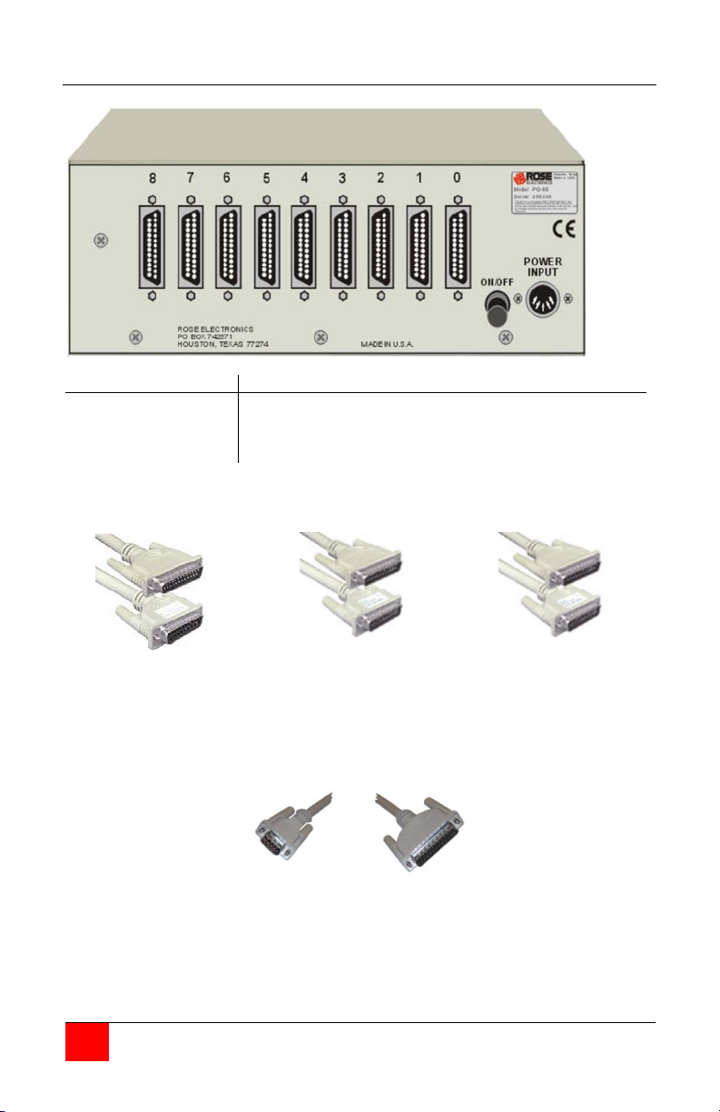
Rear panel (Serial model)
Connectors
Description
Port 0
Power input
DB25F – Connects to computer
Din5F
Switch ON/Off
Turn unit on or off
Serial 25 pin PC to PO-8S
Serial Printer to PO-8S
Modem to PO-8S
DB-25F
DB-25M
DB-25M
DB-25M
DB-25M
20
-
DB-25M
20
DB-9F
DB-25M
2
1-6-8
-
-
2
20
Ports 1-8
Rose part # CAB-PCRSx
2
3
7
5-6-8
-
-
-
-
3
2
7
20
DB25F - Connects to 8 serial devices
Rose part # CAB-PRRSx
Rose part # CAB-SMMx
2
3
7
20
-
3
-
2
-
7
-
6
Serial 9 pin PC to PO-8S
Rose part # CAB-ATRSx
2
3
6
7
-
2
-
3
-
6
-
7
3
-
5
3
-
7
PORTER INSTALLATION AND OPERATIONS MANUAL
5
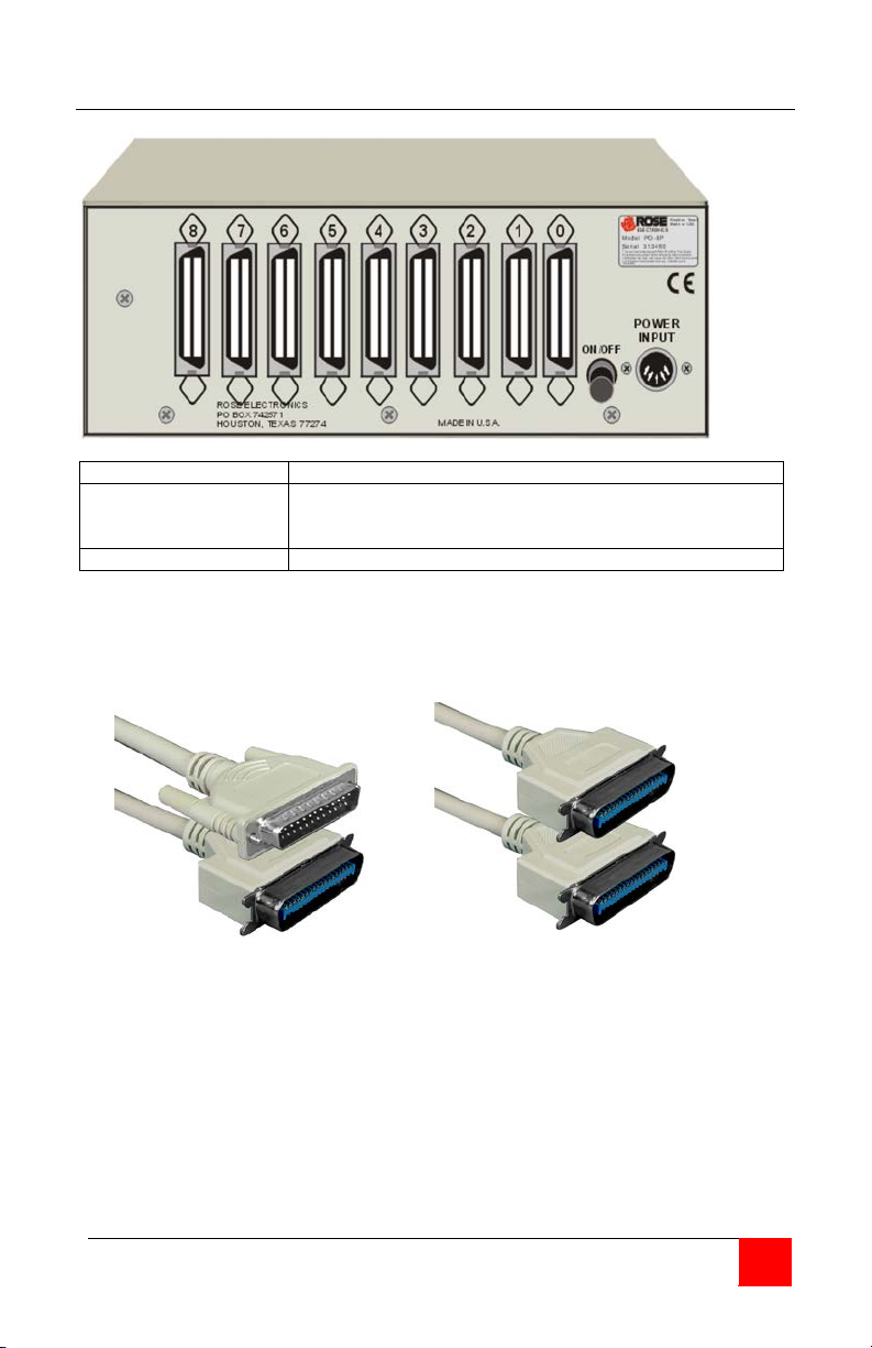
Rear panel (Parallel model)
Connectors
Description
Port 0
Centronics – Connects to computer
Switch ON/Off
Turn unit on or off
Parallel 25 pin PC to PO-8P
Rose part # CAB-IBMPx
Parallel printer to PO-8P
Rose part # CAB-PMMx
Pinout is that of a standard
PC parallel printer cable
Cable has Centronics male
Connectors on each end
Ports 1-8
Power input
Centronics - Connects to 8 parallel devices
Din5F
PORTER INSTALLATION AND OPERATIONS MANUAL

6
Quick set-up
Serial Porter
1. Connect your computer terminal to port 0 with the proper cable.
Refer to Appendix B for a list of common cables
2. Connect the power adapter, turn on the unit, power LED = Green
Power-up sequence test will start
3. If the serial factory default protocol of 9600 BAUD, no parity, 8-bits, 1-stop, and DTG
flow control for all ports is acceptable, skip step 4.
4. In this step, you will be shown a quick method of configuring the Porter. For
additional help, refer to the "Configuration" section for more detailed information.
a. Connect a computer (running a terminal emulator communication program such
a Procomm, or MasterLink supplied by Rose Electronics) or a dumb terminal to
port 0 on the Porter. Set your computer or terminal to 9600 baud, no parity, 8
bits, 1 stop bit, and full duplex.
b. Send ESC@S to the Porter. The MODE, DATA, and BUSY LEDs will light, the
configuration menu will appear.
c. For this step, you will be prompted to enter a choice of menu select numbers
(followed by a carriage return) for the item you wish to configure. You will be
prompted for all the proper responses. Enter 1 to change the protocol of any
port. Enter 7 to save the changes. Enter 8 to exit the configuration menu. A
configuration termination message appears, and the MODE, DATA, and BUSY
LEDs will go out. Note that you must save your changes before exiting the
configuration menu or they will be lost when you do step D.
d. Turn off the Porter.
5. Connect the Porter's ports 1-4 (or 8) to your devices with the correct cables.
Connect your computer to port 0. Cables must be wired correctly according to the
section on cabling.
6. If the Porter is not already on, power it on. The LEDs will sequence through power
up tests.
7. Send data from your application or print program. Data will be routed automatically
to the current connect port
8. Read this manual and use the configuration procedure if you want to change the
prefix, power-on connect port, or the broadcast group. See the section on
"Configuration" for further information.
PORTER INSTALLATION AND OPERATIONS MANUAL

7
Parallel Porter
Configuring Your PC
1. Cable your devices to ports 1-4 (or 8) with a straight-through cable that has male
Centronics connectors on each end.
2. Cable your computer to port 0 with your computer standard parallel Centronics cable.
3. Connect the power adapter and turn the unit on. The power light should glow green.
The LEDs sequence through the power up tests. The ERROR LED will be on for any
errors. See Tables II and III for the LED sequences.
4. Send data from your application or print program. Data will be routed automatically
to the current connect port.
5. Read this manual and use the configuration procedure if you want to change the
prefix, power-on connect port, or the broadcast group. See the section on PORTER
COMMANDS for further information.
If you have a serial Porter, you must make sure that you set up your serial port for the
correct baud rate and LPT1; redirection (if necessary). Redirection refers to the ability for
data sent to a parallel port to be sent to a serial port instead. Dos has a command (the
MODE command) to do this. So, for example, if you will be using the factory default
protocol of 9600 baud, 8-bit word length, no parity, and 1 stop bit, then you need to
include in your AUTOEXEC.Bat file the following statements:
MODE COM1;96,N,8,1,P
MODE LPT1:=COM1
Your application software must be set up to match the setting of the port on the Porter
that you will be using. If you will be using redirection, you must install your program(s) to
use the parallel port; otherwise, the setting of the serial port must exactly match the
setting of the Porter's port that you will be using. Many of today's software packages
have a flexible method of printing such as using the settings from the DOS MODE
command or a configurable printer setup. For these programs, setting up the program to
use the parallel port, and then redirecting LPT1 to COM1 using the DOS MODE command
is the simplest method.
However, some programs have fixed settings that can't be changed; and example of this
type of program is AutoCAD, Ventura Publishing, and others. Some of these programs
such as Ventura, can be setup to use the parallel port and redirect the output with the
DOS MODE command. For the rest of these programs this method will not work; in
these cases, you must set the serial port of your computer to exactly match the setting of
the Porter's port that you will be using.
If you have a parallel Porter, you don't need to worry about serial protocols and
redirection. You should install your software package(s) to use the parallel port when
printing. It will also be useful to put the following statement in your AUTOEXEC.BAT file:
MODE LPT1:;;P
This statement will set the parallel port for infinite retry.
PORTER INSTALLATION AND OPERATIONS MANUAL

Installation
8
Cable connection
Serial cables
Parallel cables
You should have received the Porter switch unit and a power adapter that connects to the
rear of the unit. You should have the necessary cables, supplied separately, to
interconnect the Porter with your other equipment. Ensure that the power switch is in the
off (out) position. Connect the AC power converter to a power outlet. Connect the other
end to the power input on the rear of the Porter.
Using the cables as described below connect your computer to the port labeled "0" on the
rear of the Porter. Connect your peripheral devices to the numbered ports on the rear of
the Porter.
Since industry standards vary regarding RS232 cabling, caution must be observed when
interconnecting your equipment with the Porter. Generally 5 signals or less must be
connected. They are receive, transmit, signal ground, busy in, and busy out. Porter's RxD
(pin 3) must be wired to the equipment transmit and Porter's TxD (pin 2) must be wired to
the equipment receive. Porter's signal ground (pin 7) must be connected to the
equipment signal ground. Busy in and busy out are not required when sing the X-on/X-off
protocol. When X-on/X-off is not used, busy out of the equipment must be wired to DSR
(pin 6) of the Porter and busy in of the equipment must be wired to DTR (pin 20) of the
Porter.
Busy out on the equipment is required to prevent the Porter from sending more data than
the equipment can handle. Conversely, busy in on the equipment prevents the
equipment from sending more data than the Porter can handle. While the Porter is
capable of handling data bursts at maximum baud rates, if it can not resend the data
received as fast as it gets the data, due to the equipment being busy and the input buffer
being full, then busy in on the equipment must be used. Consult your equipment manual
for information on pin numbers of your signals. Several popular cable pin outs are given
in Appendix B.
Additionally the Porter's RTS (pin 4) will be high when the Porter is powered on and may
be used to monitor whether the Porter is connected to your equipment. Refer to
Appendix A for further Porter pin out information. Refer to Appendix B for cable pin out
information. If you have a Porter with the /422 (RS-422) option, refer to Appendix A.
For a parallel unit the computer to Porter cable is the same one that would normally
connect to your printer. The Porter uses industry standard female Centronics connectors
the same as used on most parallel printers. So, instead of connecting your computer
cable t your printer, connect it to the port on the rear of the Porter labeled "0". Parallel
Porter to printer cables should have 36 pins male Centronics connectors at each end.
Connect these cables from your printers to connectors numbered 1-8 on the rear of
Porter.
PORTER INSTALLATION AND OPERATIONS MANUAL

Configuration
9
Configuration of Serial Units
The Serial Configuration Menu
Table 1 Configuration Menu Display
- - - - - - - - - - Current protocol - - - - - - - - - -
- - - - - - - - - - Power up protocol - - - - - - - - - -
Port
Baud
Parity
Len
Stop
Flow
DHS Baud
Parity
Len
Stop
Flow
DHS
0
9600
NONE 8 1
DTR
9600
NONE 8 1
DTR
1
9600
NONE 8 1
DTR
OFF 9600
NONE 8 1
DTR
OFF 2 9600
NONE 8 1
DTR
OFF 9600
NONE 8 1
DTR
OFF 3 9600
NONE 8 1
DTR
OFF 9600
NONE 8 1
DTR
OFF 4 9600
NONE 8 1
DTR
OFF 9600
NONE 8 1
DTR
OFF
Serial Configuration Menu Items
Change port protocol
After installing the Porter, it must be configured to match the protocol for your
equipment. This consists of identifying the desired characteristics of your system and
sending the appropriate control bytes to the Porter. Serial Porter units also can be
configured through an interactive menu. The configuration may be stored in the Porter’s
non-volatile memory, whose contents will not be lost when removing the Porter’s power.
The proper protocol, baud rate, number of stop / data bits, and parity information must be
set for each channel. This is done by using the interactive configuration menu, or by
sending the proper format commands to the Porter. The Porter factory set default is
9600 baud, 1 stop bit, no parity, 8 data bits, DTR/DSR handshaking. Refer to the format
command for further information.
You invoke the configuration menu – only on port 0 – by sending the command
<prefix>S from a computer funning a communication program or a dumb terminal set at
9600,N,8,1. the configuration menu will then appear as shown in Table 1. <prefix> is
factory set for the two characters ESC @ on a new unit, so initially use the string ESC @
S to get the menu.
PORTER CONFIGURATION MENU REV 3.5 COPYRIGHT 1985 – 1991 ROSE ELECTRONICS
Installed memory . . . . . . . 64K Prefix . . . . . . . . . . . . . .@
Power-on connect port . . 1 Broadcast group . . . . . 1 2 3 4 5 6 7 8
Front panel switches . . . ENABLED Command purge . . . . . DISABLED
1- Change port protocol 5- Change front panel switch control
2- Change prefix 6- Change command purge timeout
3- Change power-on connect port 7- save new configuration
4- Change broadcast port group 8- Exit configuration
Enter choice (1-8 or H for help)
In the examples below, <ENTER> means “press the ENTER key”, not type the characters
<ENTER>. Output from the Porter is shown in Courier type. Input from the user to the
menu is shown in Underlined Courier type.
This option allows the serial parameters for a port to be changed. The changeable items
are baud rate, parity, word length (data bits), stop bits, flow control, and DHS (direct
handshake). If the protocol for port 0 is changed, the menu will prompt you to change
your PC or terminal to the new baud rate and press <ENTER> to continue. Changes to
the port parameters are not made permanent until either the “Save new configuration”
option or the Keep command is used. You will be asked which port you want to change.
Enter the port number or R to change a range of ports.
PORTER INSTALLATION AND OPERATIONS MANUAL

10
Single Port
Range of Ports
Single Port with 38400 baud rate
Range of Ports with 38400 baud rate
The range option will set any changed item(s) (i.e. baud rate, parity, etc.) to the new
common value(s) for all the ports selected; however, any unchanged item(s) will remain at
the previous setting(s). If you enter “R”, you will be asked for the range of ports you want
to change. The ending port number *must* be greater than or equal to the starting port
number. Note that if you hit just a return to the ending port number, that port number will
be the same as the starting port number and only one port will be changed.
Enter choice (1-8 or H for help) 1<ENTER>
Enter the port number (0-8 or R) 3<ENTER>
Enter baud rate (19200, 9600, 7200, 4800, 3600,
2400, 1800, 1200, 600, 300, 150, 134.5, 110, 75, 50) 1200<ENTER>
Enter parity type (N=None, E+Even, O=Odd, M=Mark, S=Space) E<Enter>
Enter word length (5, 9, 7, 8) 7<ENTER>
Enter stop bits (1,2) 1<ENTER>
Enter flow control (D=DTR, X=XON/XOFF) X<ENTER>
Use DHS (direct handshaking ) (Y/N) N<ENTER>
Enter choice (1-8 or H for help) 1<ENTER>
Enter the port number (0-8 or R) R<ENTER>
Enter the starting port number (0-8) 3<ENTER>
Enter the ending port number (0-8) 4<ENTER>
Enter baud rate (19200, 9600, 7200, 4800, 3600,
2400, 1800, 1200, 600, 300, 150, 134.5, 110, 75, 50) 1200<ENTER>
Enter parity type (N=None, E=Even, O=Odd, M=Mark, S=Space) E<Enter>
Enter word length (5, 9, 7, 8) 7<ENTER>
Enter stop bits (1,2) 1<ENTER>
Enter flow control (D=DTR, X=XON/XOFF) X<ENTER>
Use DHS (direct handshaking ) (Y/N) N<ENTER>
Enter choice (1-8 or H for help) 1<ENTER>
Enter the port number (0-8 or R) R<ENTER>
Enter baud rate (38400, 19200, 9600, 7200, 4800, 3600,
2400, 1200, 600, 300, 150, 100) 1200<ENTER>
Enter parity type (N=None, E=Even, O=Odd, M=Mark, S=Space) E<Enter>
Enter word length (5, 9, 7, 8) 7<ENTER>
Enter stop bits (1,2) 1<ENTER>
Enter flow control (D=DTR, X=XON/XOFF) X<ENTER>
Use DHS (direct handshaking ) (Y/N) N<ENTER>
Enter choice (1-8 or H for help) 1<ENTER>
Enter the port number (0-8 or R) R<ENTER>
Enter the starting port number (0-8) 3<ENTER>
Enter the ending port number (0-8) 4<ENTER>
Enter baud rate (38400, 19200, 9600, 7200, 4800, 3600,
2400, 1200, 600, 300, 150, 100) 2400<ENTER>
Enter parity type (N=None, E=Even, O=Odd, M=Mark, S=Space) E<Enter>
Enter word length (5, 9, 7, 8) 7<ENTER>
Enter stop bits (1,2) 1<ENTER>
Enter flow control (D=DTR, X=XON/XOFF) X<ENTER>
Use DHS (direct handshaking ) (Y/N) N<ENTER>
* This question is not asked when configuring Port 0
PORTER INSTALLATION AND OPERATIONS MANUAL

11
Change prefix
Change power-on connect port
Change broadcast port group
Change front panel switch control
This option allows changing of the Porter’s prefix. As shipped, the unit’s prefix is set to
the two characters ESC@. The prefix change is not made permanent until either the
“Save new configuration” option or the Keep command is used.
Enter choice (1-8 or H for help) 2<ENTER>
Enter new prefix (1-6 characters) #S#<ENTER>
This allows changing of the port that the Porter initially connects to when it is powered
on. You may enter a port number (except port 0), N for null destination, or B for
broadcast. See the section on operation for more information on null destination and
broadcast mode.
Enter choice (1-8 or H for help) 2<ENTER>
Enter power-on connect port (1-4,N,B) 1<ENTER>
This option allows you to change the broadcast mask. This determines which ports have
data transmitted out to them when broadcast mode is used. You may enter any
combination of ports (except 0), but you must select at least one port or the change is
ignored. The following example sets ports 1, 2, and 4 to get data during broadcast. The
factory set default is for all ports (except 0) on the unit to be enabled for broadcast. The
broadcast mask can also be changed with the <prefix> + Mxx command (see the
sections on “Commands”.
Enter choice (1-8 or H for help) 4<ENTER>
Enter a port number to select for broadcast,
return only to terminate (1-4) 1<ENTER>
Enter a port number to select for broadcast,
return only to terminate (1-4) 2<ENTER>
Enter a port number to select for broadcast,
return only to terminate (1-4) 4<ENTER>
Enter a port number to select for broadcast,
return only to terminate (1-4) <ENTER>
This allows locking the front panel switches to prevent manual changing of the connect
port (see “Manual Mode”). You can also unlock the switches with this option. The
factory set default is to have the switches unlocked. Locking the switches does not
prevent use of the diagnostic modes at power-up.
Enter choice (1-8 or H for help) 5<ENTER>
Disable front panel switches (D=disables, E=Enables) E<ENTER>
PORTER INSTALLATION AND OPERATIONS MANUAL

12
Change command purge timeout
With 38400 baud option
Save new configuration
Exit configuration
Help
1- PROTOCOL
The protocol means the . . .
The command purge timeout determines whether to treat a partial prefix as a command
that hasn’t finished being received, or as data. When a value other than 0 is entered, it is
treated as a 20
second time value is used). If a command prefix is entered partially, and this time period
elapses, the partial prefix is purged and transmitted to the current connect port(s) as if it
were data. This is useful for certain programs that may leave a partial prefix at the end of
a data block. When this value is set to 0, partial prefixes will be held in the unit until
either the command is completed or a non-prefix character is received. This is the factory
set default.
Enter choice (1-8 or H for help) 6<ENTER>
Enter new command purge timeout in 20ths of a second (0-254;
0 disables) 30<ENTER>
Enter choice (1-8 or H for help) 6<ENTER>
Enter new command purge timeout in 40ths of a second (0-254;
0 disables) 80<ENTER>
This option allows the current configuration to be saved permanently in non-volatile
memory. Do not use this option until you are sure that the current settings are working
properly.
Enter choice (1-8 or H for help) 7<ENTER>
Are you sure (Y/N) Y<ENTER>
This option exits the configuration menu and returns the Porter to normal operation. All
data in buffer memory is erased. The default connect port is selected as if the unit was
just powered up.
Enter choice (1-8 or H for help) <ENTER>
This option gives a brief description of what each command does.
Enter choice (1-8 or H for help) H<ENTER>
The configuration menu shows the amount of memory installed, other various settings,
and the current and power-on protocol settings for each port. Configure the Porter by
entering the number of an item on the menu
th
of a second time value (if 38400 baud option is present, a 40th of a
2- PREFIX
3- POWER-ON CONNECT
4- BROADCAST GROUP
5- FRONT SWITCHES
6- PURGE TIMEOUT
7- SAVE CHANGES
8- EXIT
H- HELP
Hit enter key to see configuration parameters or enter choice
The programmable part . . .
Port 0 connects to . . .
Several ports that . . .
To disable/enable . . .
After this time . . .
Saving changes puts . . .
Exit from the . . .
Displays this screen . . .
PORTER INSTALLATION AND OPERATIONS MANUAL

13
Configuration of Parallel Units
The Centronics parallel interface is usually implemented consistently; however there are
some variations. Three lines are used to implement the flow control part of the interface.
They are strobe, acknowledge, and busy. Most Apple computer parallel interface cards
do not implement the busy signal. Some Radio Shack printers do not issue an
acknowledge signal. Most other printers use both the acknowledge and busy. There is a
provision for the Porter to handshake with all of this equipment. Each port except the
master port may be configured to ignore acknowledge, busy, or both signals by sending
the proper format commands to the Porter. The settings made by these format
commands can then be made permanent by using the keep command.
The Porter factory set default is to require acknowledge and busy for each port. Refer to
the format command for further information.
PORTER INSTALLATION AND OPERATIONS MANUAL

Power Up Tests
14
Power Up Initial Display
Table II LED Power up Display
M D B E 1 2 3 4 5 6 7 8
1st
All LEDS on
2nd
Test 1: EPROM checked
3rd
Test 2: 16K RAM buffer
Test 2: 64k RAM buffer
Test 2: 256k RAM buffer
4th
Test 3: Static ram
5th
Test 4: Non-Volatile ram
6th
Unit ready
Program Checksum Test
Buffer Memory Sizing And Read/Write Test
Static Ram Read/Write Test
Non-volatile Ram Tests
Push in the power switch to turn the unit on. Porter goes through a power up self-test
which checks the main functions of its electronics. The leftmost LED labeled POWER
should glow green and the other red LEDs should all turn on. Then the unit will cycle
through four tests lighting up LEDs 1 through 4 as each test is performed. Errors are
indicated by the ERROR LED lighting and the unit halting. See TABLE II for the full
sequence of the power up LED display and TABLE III for error displays.
Legend: M=Mode LED D=Data LED B=Busy LED E=Error LED
This test verifies that the unit’s internal program is valid by performing a checksum test.
If a fault exists, a program checksum error shows on the LEDs as error 1, as shown in
TABLE III. The unit will immediately halt. This error requires that the unit be serviced.
In this test, the Porter automatically determines the amount of butter memory present
and indicates the amount via the status LEDs as shown in TABLE III. The buffer memory
is then tested to ensure that the memory system is operational. Any failure will cause the
error 2 condition to be displayed, as shown in TABLE II, indicating that a buffer memory
data error has occurred. The unit will not continue its further tests and will halt. An error
indicates that the unit requires servicing.
The next test is for static ram. Since the Porter has no static ram, this test is displayed as
shown in TABLE II for consistency with other Rose products.
The fourth and final power-up test is for the non-volatile memory. A series of tests are
performed. An error shown by the LEDs as error 4 indicates that the data in the nonvolatile memory has been corrupted. To attempt to rewrite the default parameters push
the SELECT switch then the ADVANCE switch. If the error condition goes out, the unit
may be powered up again to see if it halts at error 4 again. If it still displays error 4, a fatal
error has occurred and servicing is required. If the unit displays an error 45, the default
parameters were not written correctly. This is a fatal error and servicing is required.
If the unit recovers from the error the configuration parameters have been returned to
their default settings and the unit must be configured again if these default settings are
unacceptable. This condition should not normally occur.
= LED off = LED on
PORTER INSTALLATION AND OPERATIONS MANUAL

15
Table III LED Error Display
M D B E 1 2 3 4 5 6 7 8
Error 1
Error 2
Error 3
Error 4
Error 41
Error 43
Error 45
Error 46
Error 47
Error 48
Error 1
. . . . . .
EPROM checksum failure
Error 2
. . . . . .
RAM buffer memory failure
Error 3
. . . . . .
Static ram failure
Error 4
. . . . . .
Non-volatile ram checksum failure
Error 41
. . . . . .
Non-volatile ram in wrong box type
Error 43
. . . . . .
Non-volatile ram memory failure
Error 45
. . . . . .
Restore to default configuration failure
Error 46
. . . . . .
A port that is not allowed is present
Error 47
. . . . . .
More ports in box than listed in the non-volatile ram
Error 48
. . . . . .
Wrong EPROM version
If it does it indicates that possibly the unit has been subjected to a strong static discharge
or surge on its incoming power or signal lines. The other possibility is an internal chip
failure.
In addition to the data in the non-volatile ram, several other tests on the non-volatile ram
are done. If any error 4 occurs and a reset t defaults does not correct it, the unit needs
servicing. The additional errors listed below are for technical support purposes only.
Legend: M=Mode LED D=Data LED B=Busy LED E=Error LED
= LED off = LED on
Any error not listed requires that the unit be serviced.
PORTER INSTALLATION AND OPERATIONS MANUAL

Operation
16
Initial state
Operating Modes
Normal mode
Sending data from the master to the selected port
Receiving data from a selected port
Null destination
Following the successful completion of its power up test, the Porter turns all its LEDs off.
The port LEDs will display the initial connect state (all dark for null destination, several lit
for broadcast mode, or one lit for single port connect). The status LEDs will display the
current port activity.
The Porter has several operating modes. Normal, null destination, and broadcast modes
are used for data transfer. Configuration (menu) mode is used to set up the unit.
Diagnostic mode is used to check the unit for faults. Manual mode allows front panel
switches to change the currently connected port.
Data flow is controlled by sending commands which may be intermixed with data. The
port selected may be changed by sending the proper command. When a port is selected,
normal communication occurs between the master port and the selected port. For serial
models full duplex communication is in effect; data may flow in either direction between
the master port and the selected port. For parallel models data is strobed into the master
port and out of the selected port. Also the status signals such as “PAPER END” are
passed through. Different protocols may be I effect on each port with the Porter making
the conversions automatically.
When transmitting data from the master port to the selected port the data will
immediately be sent unless the selected port is busy, in which case the data will go into
the selected port’s transmit buffer memory. If the buffer becomes full, the master port
will be signaled to stop sending data according to the flow control protocol set for it.
When a new port is selected and data remains in the previously selected port’s buffer,
data will continue to be sent from the previous port’s buffer to the device it is connected
to according to the flow control protocol currently in operation. Further data sent from
the master will go to the newly selected port or its buffer. Thus each port has its own
transmit buffer memory and data may be transmitted from each port’s buffer memory
simultaneously.
Data may be received from a selected port only on the serial models. Parallel units do not
allow incoming data on ports 1-8. Data received from a selected port will be immediately
sent out on the master port unless the master port is bus, in which case the data will go
into the selected port’s receive buffer. If the buffer becomes full the selected port will be
signaled to stop sending data according to the flow control protocol in operation.
Data received on a port which is not selected will be put in to that port’s receive buffer. If
a new port is selected which has data in it’s receive buffer, that data will immediately be
sent to the master port according to the flow control protocol in operation. Further data
received on the newly selected port will be sent to the master port immediately or placed
at the end of data currently in the buffer.
When the null destination (prefix + 9) command is in effect, no ports are considered
connected. Any data received on ports 1-8 will go into the respective receive buffer. All
the port LEDs remain off. Commands received via port 0 will continue to be recognized,
all other data received on port 0 is discarded. Null destination is terminated by sending
another connect command or the broadcast mode command.
PORTER INSTALLATION AND OPERATIONS MANUAL

17
Broadcast mode
Diagnostic mode
Configuration mode
Manual mode
When the <prefix>B broadcast mode command is entered, all ports enabled for
broadcast (via the configuration menu or the <prefix> +Mxx command) will light their
corresponding port LEDs. On serial units, all ports enabled for broadcast will immediately
have their receive buffers cleared.
Any data sent to port 0 during broadcast mode is transmitted simultaneously to all
enabled ports. Commands, with the exception of the <prefix>+Mxx command, continue
to be processed normally. Broadcast mode is terminated by sending a connect
command or the null destination command.
Side effects of broadcast mode
On serial units, port 0 must not be set to 19,200 baud (38400 baud if that option is
present) during broadcast mode. Due to the overhead of transmitting to multiple ports,
the Porter cannot process incoming data for broadcast at tis baud rate. Attempting this
will cause the ERROR LED to flicker and characters to be lost on output.
Also, on serial units during broadcast mode, incoming data on ports 1-8 is ignored.
However, X-on and X-off characters sent into ports set for X-on / X-off handshaking
continue to be processed.
On parallel units, the ERROR LED is always off during broadcast mode.
Also on parallel units the BUSY LED reflects the state of BUSY out on port 0,
not BUSY in on the connected port.
Also, on parallel units all ports enabled for broadcast must be hooked up to something. If
this is not done, broadcasting will stop when the unconnected port transmit buffer fills
up, as unconnected parallel ports are not set ot ready as with serial ports.
As mentioned before, the <prefix>Mxx (change broadcast mask) command does not
function during broadcast mode. To change the mask you ust first exit broadcast mode
(preferably with the <prefix>9 null destination command), issue the <prefix>Mxx
command, then reenter broadcast mode.
This mode allows the unit to self test itself. You can also restore the factory set
configuration from this mode. Refer to the section on “Diagnostic Modes” for
information on this mode.
This mode is activated by the configuration menu command <prefix>S. When this mode
is active, the MODE, DATA, and BUSY LEDs will all be lit. Data transfer from or to ports
1-8 is ignored in this mode. See “The Configuration Menu” for more information on this
mode.
This feature is used for manually establishing a port connection. It is useful for port
selection where software codes may not be desired to be sent. To enter the manual
mode, momentarily press both switches. The mode light will illuminate to indicate that
the manual mode has been entered. Pressing the ADVANCE switch will cause the port
selected to be changed to the next port. To leave the manual mode, momentarily press
both switches again. The mode light will go blank to indicate you are in the normal mode.
In the manual mode, connect commands sent to port 0 will still take effect.
PORTER INSTALLATION AND OPERATIONS MANUAL

18
The manual mode can be used to exit the null destination state, but it cannot be used to
set the unit to the null destination state. You must use the (prefix + 9) command to do
this.
Manual mode may be entered if the front panel switches have been disabled (locked) by
the <prefix>Lx command or the configuration menu. Manual mode may be entered and
then exited without altering the unit’s operating mode and port connection if the advance
switch is not pressed by itself while manual mode is active
PORTER INSTALLATION AND OPERATIONS MANUAL

19
Front Panel
Table IV LED Operation Display
M D B E 1 2 3 4 5 6 7 8
Note 1
Note 2
Note 3
X X X X X X X X
Note 4
Note 5
Note 1
. . . . . .
Unit operational, connected to port 1
Note 2
. . . . . .
Unit operational, null destination mode set
Note 3
. . . . . .
Unit operational, in broadcast mode with all ports enabled
Note 4
. . . . . .
Unit is in manual mode, displays current port connected
Note 5
. . . . . .
Unit is in configuration (setup) mode
The front panel is useful for observing the status of the Porter and manually changing the
port selection.
The front panel switches, labeled SELECT and ADVANCE are used to manually change
modes and port selection as described in the section on operating modes. They may be
disabled or enabled under program control
(see “Commands”).
The front panel LEDs are in two groups, the status LEDs and the port select LEDs. The
port select LEDs display the currently selected ports as long as the error light is not lit.
The status LEDs consist of Power, Mode, Data, Busy, and Error. The PORT SELECT LEDs
display the current connection between the master port and the peripheral ports. The
POWER LED is lit when power is connected to the unit and the on/off switch is in the on
position. The MODE LED displays the current mode that the Porter is in. When the LED
is lit the unit is in the manual mode, when it is dark the unit is in the normal mode. If it is
on along with the DATA and BUSY LEDs, the unit is in the configuration menu. The DATA
LED displays the presence of data being sent across the selected port. When illuminated
data is being transferred across the selected port connection. The BUSY LED displays
the state of the flow control of the selected port. When it is illuminated it indicates that
the flow of data has been inhibited across the selected port connection. The ERROR LED
displays any data receive errors encountered on serial ports and reflects the state of the
ERROR pin within the connected port on parallel ports.
Legend: M=Mode LED D=Data LED B=Busy LED E=Error LED
X + may vary, described below
= LED off = LED on
PORTER INSTALLATION AND OPERATIONS MANUAL

20
Porter Commands
Porter command set
Code
Description
Prefix + 1
Connect port 1 to port 0
Prefix + 2
Connect port 2 to port 0
Prefix + 3
Connect port 3 to port 0
Prefix + 4
Connect port 4 to port 0
Prefix + 5
Connect port 5 to port 0
Prefix + 6
Connect port 6 to port 0
Prefix + 7
Connect port 7 to port 0
Prefix + 8
Connect port 8 to port 0
Prefix + 9
Set null destination (connect to nothing)
Prefix + A
Any data available
Prefix + B
Set Broadcast mode
Prefix + Cnxx
Copy buffer n xx times
Prefix + Dn
Set initial power-up destination
Prefix + Fnxxxx
Set serial format and baud rate / xxxx in hexadecimal
Prefix + Gn
Go, resume flow of data on port n
Prefix In
Initialize printer on port n; valid on parallel units only
Prefix K
Keep current setup in non-volatile memory
Prefix Lx
Enable/Disable front panel switches
Prefix Mxxx
Set broadcast Mask (which port to broadcast to)
Prefix + Pxxxxxx = null
Set new Prefix from 1 to 6 characters
Prefix + Rn
Report state of Ready (DSR) on port n
Prefix + S
Start setup (configuration menu)
Prefix + Tnnn
Set prefix purge Timeout of nnn/20 seconds
Prefix + Wn
Wait, suspend flow of data on port n
Prefix + Zn
Zero (clear) buffer n
The command codes shown below control various functions of the Porter. All codes
begin with a user defined prefix that is 1-6 characters long. Zero (null, not ASCII “O”) may
not be used as part of the prefix. The prefix can be stored in non-volatile memory to
become a semi-permanent part of the control codes. The prefix should be chosen so as
not to interfere with other control codes used in you equipment. The purpose of the
prefix is to uniquely separate the code from the data you are transmitting. The factory set
prefix is 27,64 (the two characters ESC,@).Following the prefix is a one character
command and optional operands. The 8
or checking for an incoming prefix on port 0.
The + signs under “Code” are for illustrative purposes only. Do not use them in the
command string. All command letters are case sensitive – use upper case letters only.
th
(high) bit is ignored when setting a new prefix
xx is decimal, leading zero required is xx < 10
n = 1-8 for ports, 9 for null, B for broadcast
x = 0 unlocks, x = 1 locks
xx = two hexadecimal digits
must be terminated with null to delimit string
with 38400 baud option, nnn/ 40 seconds
PORTER INSTALLATION AND OPERATIONS MANUAL

21
Connect commands 1-8
Connect to Null Destination (9) command
Any Data Available Command
Broadcast mode command
Set port format command
Serial format codes by character
Character w
Character x
Character y
Character z
0 = none
0 = DTR/DSR
0 = 1 stop, 8 data
1 = 50
2 = odd
4 = Direct (DHS)*
2 = 1 stop, 7 data
2 = 75
6 = even
8 = X-on / X-off
4 = 1 stop, 6 data
3 = 110
A = mark
C = X-on / X-off + DHS*
6 = 1 stop, 5 data
4 = 134.5
E = space
8 = 2 stop, 8 data
5 = 150
A = 2 stop, 7 data
6 = 300
C = 2 stop, 6 data
7 = 600
E = 1.5 stop, 5 data
8 = 1200
9 = 1800
A = 2400
B = 3600
C = 4800
D = 7200
E = 9600
F = 19200
The connect commands allow selection of the current port connection. Commands 5-8
on a 4 port unit will connect to ports 1-4, respectively. The format of this command is
prefix + ASCII port number to connect to.
This command selects the null destination. No further data is passed through to the ports
1-8 transmit buffers until a connect 1-8 or broadcast mode command is received. For
further information see “Null Destination” under “Operating Modes”.
This command, applicable on serial units only, checks the buffers of ports 1-8 to see if
there is any data available and returns a coded byte containing the results. In this coded
byte, each bit position corresponds to a port; i.e. bit 0 corresponds to port 1, bit 1
corresponds to port 2, etc. If the port has any data available, the corresponding bit is set
to 1. The format of this command is prefix + A.
This command places the Porter into broadcast mode. See the section on “Broadcast
Mode” for further information. To end broadcast mode, send any connect command.
The serial format consists of the flow control protocol, baud rate, word length, parity, and
number of stop bits. Each port can be individually programmed with this command. The
format is the prefix + F + port number + wxyz where wxyz are send in hexadecimal
notation. The binary value of each bit is shown below. The default for each channel is
9600 baud, 8 bits, no parity, one stop bit, DTR/DSR handshake. For example to set the
default value on Port 5 the string would be prefix + F + 000E. Four hex digits are
required to enter the format code correctly. Note that with the 38400 baud option, the
baud rates are doubled. The only parameters changeable on parallel ports are bits 9,8 in
character x. These are also descried below.
Parity
Handshake
Stop & Data Bits
Baud rate
PORTER INSTALLATION AND OPERATIONS MANUAL

22
Format codes by bit
Character w : bits 15 - 12
Bits 15 – 14
00 = Odd parity
10 = Mark parity
Bit 13
0 = Parity off
1 = Parity on
Bit 12
unused
Ch ara cte r x: bi ts 1 1 - 8
Bit 11
0 = DTR flow control
1 = X-on/X-off flow control
Bit 10
0 = No DHS*
1 = Use DHS*
Bit 9**
0 = Busy required
1 = Busy ignored
Bit 8**
0 = Ack required
1 = Ack ignored
Character y: bits 7-4
Bit 7
O = 1 stop bit
1 = 2 stop bits
Bit 6-5
00 = 8 data bits
10 = 6 data bits
Bit 4
Unused
Character z: bits 3-0
Character
Binary
Baud Rate
Character
Binary
Baud Rate
1
0001
50 9 1001
1800
2
0010
75 A 1010
2400
3
0011
110 B 1011
3600 4 0100
134.5 C 1100
4800 5 0101
150 D 1101
7200 6 0110
300 E 1110
9600 7 0111
600 F 1111
19200
8
1000
1200 0 0000
INVALID
Serial format codes by character for 38400 baud option
Character w
Parity
Character x
Handshake
Character y
Stop & Data Bits
Character z
baud Rate
0 = none
0 = DTR/DSR
0 = 1 stop, 8 data
1 = 100
2 = odd
4 = Direct (DHS)*
2 = 1 stop, 7 data
2 = 150
6 = even
8 = X-on/X-off
4= 1 stop, 6 data
3 = INVALID
A = mark
C = X-on/X-off + DHS*
6= 1 stop, 5 data
4 = INVALID
E = space
8= 2 stop, 8 data
5 = 300
A= 2 stop, 7 data
6 = 600
C= 2 stop, 6 data
7 = 1200
E= 1.5 stop, 5 data
8 = 2400
9 = 3600
A = 4800
B = 7200
C = 9600
D = INVALID
E = 19200
F = 38400
01 = Even parity
01 = 7 data bits
11 = Space parity
11 = 5 data bits
PORTER INSTALLATION AND OPERATIONS MANUAL

23
Format codes by bit for 38400 baud option
Character w : bits 15 - 12
Bits 15 – 14
00 = Odd parity
10 = Mark parity
Bit 13
0 = Parity off
1 = Parity on
Bit 12
unused
Ch ara cte r x: bi ts 1 1 - 8
Bit 11
0 = DTR flow control
1 = X-on/X-off flow control
Bit 10
0 = No DHS*
1 = Use DHS*
Bit 9**
0 = Busy required
1 = Busy ignored
Bit 8**
0 = Ack required
1 = Ack ignored
Character y: bits 7-4
Bit 7
O = 1 stop bit
1 = 2 stop bits
Bit 6-5
00 = 8 data bits
10 = 6 data bits
Bit 4
Unused
Character z: bits 3-0
Character
Binary
Baud Rate
Character
Binary
Baud Rate
1
0001
100 9 1001
3600
2
0010
150 A 1010
4800
3
0011
INVALID
B
1011
7200 4 0100
INVALID
C
1100
9600 5 0101
300 D 1101
INVALID
6
0110
600 E 1110
19200
7
0111
1200 F 1111
38400
8
1000
2400 0 0000
INVALID
*
Copy from buffer command
Example of the copy command
If DHS (direct handshake) is set on a given port, the port, when selected, will pass its
DSR signal directly back to port 0’s DTR signal, and port 0’s DSR signal will pass directly
to the DTR signal on the selected port. DHS cannot be set on port 0. This is useful for
dealing with modems.
** For parallel units only. These are the only parameters used by parallel units. Ignored if
set on a serial unit. These parameters cannot be set for port 0.
The copy command is useful for sending multiple files of data while only storing one copy
of the data. The command requires an additional operand of the number of times to copy
the buffer. The format of this command is the prefix + the port number + a two digit
decimal number specifying the number of copies to be made. The zero buffer command
may be used to cancel a copy in progress. The maximum number of copies allowed is 14.
Entering the copy command with > 14 copies causes it to be ignored.
To use the copy command, first connect to the port you wish to send copies out of. Use
the Z (Zero Buffer) command to clear the buffer, and then send the first (original) copy.
Then issue the copy command to send the remaining copies. After sending the copy
command you may connect to other ports without disturbing the copying process.
01 = Even parity
01 = 7 data bits
11 = Space parity
11 = 5 data bits
PORTER INSTALLATION AND OPERATIONS MANUAL

24
Set Initial destination command
Go command
Initialize command (Parallel units only)
Keep command
Enable/Disable front panel switches command
Set broadcast mask command
Set prefix command
This command is used to set the initial destination the Porter selects when it is powered
up. The syntax of this command is prefix + Dx, where x is the port number (1-8), 9 for
null destination, or B for broadcast.
The Go command reverses the action of the Wait command. (See “Wait Command”,
below.) The port’s DTR is set to high, and if the port is configured for X-on/X-off operation
a X-on character is sent. Also, transmission suspended by a Wait command is resumed.
The syntax of this command is prefix + G + port number.
The initialize command causes a parallel port INIT signal to be pulsed low. This initializes
a printer if one is connected. The command is ignored on serial units. The syntax of this
command is prefix + I + port number.
This command allows the current setup parameter to be saved in non-volatile memory
and to become the default configuration. The parameters saved are the prefix characters,
initial destination, timeout, and format control. You should ensure that the unit is working
properly before using this command. Also make a written record of the configuration for
your future reference. The format of this command is prefix + K.
This command allows you to disable (lock) or enable (unlock) the front panel switches.
The syntax of this command is prefix + Lx, where x = 0 to unlock, or 1 to lock. Locking
the switches does not prevent use of the diagnostic mode at power up.
This command lets you change which ports are enabled for data transmission when the
broadcast mode is used. The factory setting is to have all available ports except port 0
enabled for broadcast. The syntax of this command is prefix + M + xy, where xy are two
hex digits. X controls ports 8-5, and y controls ports 4-1. The most significant bit controls
port 8, the next bit port 7, and so on with the least significant bit controlling port 1.
Setting a bit to 1 enables the corresponding port for broadcast; setting a bit to 0 disables
the port for broadcast.
This command alters the prefix used at the beginning of all commands. The new prefix
will take place immediately after receipt. It is recommended that the prefix be chosen
once and used consistently. Altering the prefix is useful for separating Porter’s select
codes from other device codes which may be used for other functions. It is also useful
for chaining multiple Porters together, described further in the section on chaining.
The syntax for this command is the old prefix + P + the new prefix + null. The null (byte
= 0, Ctrl-@ on a PC keyboard) is used to terminate the prefix code and is required to
determine the amount of characters in the prefix. Null may not occur as part of the prefix
code. The factory default for the prefix is ascii 27,64 representing the two characters
ESC@. The high (8
ignored when the unit checks for an incoming prefix on port 0.
th
) bit is always set to 0 when entering a new prefix, as the 8th bit is
PORTER INSTALLATION AND OPERATIONS MANUAL

25
Ready (Check DSR) command
If this command is issued when there is reverse channel data traffic, it may not respond.
Setup (Configuration) menu commands
Timeout (command purge) command
Wait command
Zero (clear) command
This command allows a program to determine if a given serial port’s DSR (pin 6) is in the
ready state (+12V), or the busy state (-12V). The syntax of this command is prefix + port
number 0-8. A single byte is returned: ASCII “0” if the specified port is in the busy state,
and “1” if it is in the ready state. Note that a port with no device connected will read as
“ready” due to the internal pull-up resistor provided for pin 6.
Since this command returns an answer, you must ensure that no reverse channel data
(data coming from ports 1-8) is present when this command is issued. The safest way to
use this command is to use the connect 9 (Null Destination) command first, then after
issuing the Ready command and receiving its answer re-issue the appropriate connect
command to re-connect.
The configuration menu is invoked by the prefix + S command. You would normally not
issue this command except by manual entry from a communication program or dumb
terminal. For more information on the configuration menu see “The Configuration Menu”.
This allows changing the command purge timeout. The timeout value may range from
000-255. Setting a value of 000 disables the command purge timeout. The syntax of this
command is prefix + T + nnn. Leading zeros are required. For more information on te
command purge timeout se the “Configuration Menu” section under “Change command
purge timeout value”.
The Wait command causes two things to happen to the port n that it is used on. First,
any transmission that may be in progress is suspended. Second, the port’s DTR is set to
low, and if the port is configured for X-on/X-off operation a X-off character is sent. This
state is cleared with the Go command. The syntax of this command is prefix + W + port
number.
This command is used to clear the buffer and cancel any pending data transfers on the
port specified. This command should be used prior to using the copy command to
ensure that the proper data will be copied. Zero is set for an individual port buffer by
sending the prefix + Z + port number.
PORTER INSTALLATION AND OPERATIONS MANUAL

26
Applications
Buffering
Chaining Multiple Porters Together
Writing Programs to Control the Porter
Procedure for sending Data
Procedure for Receiving Data
The switch may have a buffer of 16, 64, or 256 Kbytes of memory. The memory is
allocated evenly to each port. For the serial models half of the memory for each port
would be allocated to the transmit buffer and the other half to the receive buffer. For
example for an 8 channel serial model with 16k bytes of buffer each port would have 1k
for transmit and 1k for receive. For parallel models each port has only a transmit buffer
with the buffer being divided equally among all channels. For example a 4 channel
parallel model with 64k bytes of buffer would have 16k bytes allocated to each port.
When broadcast mode is used, the main port will go “busy” if any of the buffers
belonging to ports enabled for broadcast become full.
The units may be chained together in an unlimited fashion to connect 1 master port to
more than the number of peripheral ports available on one Porter unit by interconnecting
more than one Porter unit. The peripheral ports on a master unit are connected to the
master ports on the expansion units. In order to access ports on the expansion unit(s), a
different prefix code must be set into the expansion units. By sending the master unit’s
code followed by the expansion unit’s code, a peripheral port may be accessed.
For example, use the default prefix on the master unit. Set the prefix on the expansion
unit to %^. Connect peripheral port 2 on the master unit to the master port on the
expansion unit. To access port 5 on the expansion unit from the master port on the
master unit send the code ESC@2%^5. There is no limit to the number of expansion
units that may be added.
The procedure for sending data to multiple output devices using the Porter is
straightforward and easy to implement from a program.
1. Initialize the serial port connected to the Porter
2. Send the control code to connect to the first device.
3. Send the data to the first device.
4. Continue to step 2.
One common use of the Porter is to interrogate a group of devices to collect data from
them. A program that does this should use the following algorithm:
1. Initialize the serial port connected to the Porter, prepare to receive characters.
2. Use the any data available command and read the coded byte returned. If there is
any data available follow steps 3-5 below.
3. Send the control code to connect to the first device.
4. Receive and store data fro this device.
5. When the program wishes to change ports to listen to another device:
A. Either drop DTR (hardware handshake) or send an X-off (X-on/X-off).
B. Check the receiver to ensure that a character was not received while step 4a
was being carried out. Read and store the character if this happened.
C. Send the control code to connect to the next device
D. Carry out any steps needed to prepare to receive data from the next device.
E. Either raise DTR (hardware handshake) or send an X-on (X-on/X-off)
F. Proceed to step 3.
PORTER INSTALLATION AND OPERATIONS MANUAL

27
Diagnostic
Diagnostic Tests
Short Test
Long test without loopback
You can execute some special diagnostic tests to determine if the Porter has any
problems. There are three groups of tests as shown below.
The short test, which is exactly the same as the power up test, is executed by pressing
both ADVVANCE and SELECT while powering up the unit. The long test without loopback
is selected by powering on while holding in the SELECT switch only. The long test with
loopback (which requires loopback connectors as described below) is selected by
powering on while holding in the ADVANCE switch only.
The long tests do a more extensive memory test and do tests on the ports. For this
reason, all devices (except the loopback connectors on the loopback test) must be
disconnected from the unit’s ports when the long tests are running. The short test is
similar to the power up test but continuously cycles, and allows reloading of the factory
default settings. The tests continuously cycle and halt if an error is determined. See
Tables V and VI for the various LED displays.
This group of tests is entered by pressing both the ADVANCE and SELECT switches while
powering up the unit. They are also executed once on every power-up. These tests are
exactly the same tests as those performed during power up sequence. You enter this
state for a continuous test of the Porter functions or to reload the factory default settings
as described below.
Test 1 – EPROM program checksum test
Test 2 – Buffer memory sizing and read/write test
Test 3 – Static ram read/write test
Test 4 – Non-Volatile ram checksum test
Tests 1 – 4 are the same as the power-up test.
This group of tests are entered by pressing the SELECT switch only while powering up
the unit with the on/off switch. All equipment should be disconnected from the Porter
prior to running this test.
Test 1 – EPROM program checksum test
This test is the same as the “Short Test” described above.
Test 2 – Extended dynamic ram test
This test checks the dynamic ram more extensively than the short test or the power up
test. The test takes longer to perform. If this test fails (see Table VI) then the unit must
be serviced. Other LEDs may be lit also indicating the amount of memory that is installed
(see Table V). The failing board and memory device can be determined by pressing the
ADVANCE switch. The BUF LED will be lit if the failing board is the base mother board or
the bottom-most memory board installed. The DATA LED will be lit if the failing board is
the second from the bottom. The BUSY LED will be lit for the third board, and the LED
#0 will be lit for the fourth board. The LEDs 1-8 correspond to the physical placement of
the failing chip. If the failing chip is the one all the way to the left, then LED 1 will be lit.
If the failing chip is the one all the way to the right, then LED 8 will be lit. The chips in the
middle correspond appropriately. Hitting the SELECT switch will retry the test. In order
to bypass this test completely, both the ADVANCE and SELECT switches may be
pressed.
PORTER INSTALLATION AND OPERATIONS MANUAL

28
Table V Diagnostics LED Display
M D B E 1 2 3 4 5 6 7 8
1st
All LEDS on
2nd
Test 1: EPROM checked
3rd
Test 2: 16K RAM buffer
Test 2: 64k RAM buffer
Test 2: 256k RAM buffer
4th
Test 3: Static ram
5th
Test 4: Non-Volatile ram
6th
Test 5: Port type test
7th
Test 6: Module test
Test 3 – Static ram read/write test
This test is the same as in the ‘Short Test’
Test 4 – Non-volatile RAM checksum test
This test is the same as in the ‘Short Test’
Test 5 – Port addressing test
This test ensures that the contents of non-volatile memory agree with the port
configuration. If this test fails (see Table VI) then the configuration memory has been
corrupted or a port communication chip has failed. Reload the factory default settings as
described below and retry the test. Make sure there are no cables connected to the
Porter. Re-run the test, if the test still fails then the unit must be serviced. The ADVANCE
switch may be pressed to determine which port is the failing port. BUF, DATA, and BUSY
LEDs will all be lit. The LEDs of all ports which pass will be it. A failing port will have its
corresponding LED off. The SELECT switch may be pressed to execute the test again. In
order to bypass this test completely, both the ADVANCE and SELECT switches may be
pressed.
Test 6 – Module test without loopback
This test ensures that there are no signal shorts on a port. In order for this test to pass,
no equipment should be connected to the Porter. If this test fails (see TABLE VI) then a
port communication chip has failed and the unit must be serviced. The ADVANCE switch
may be pressed to determine which port is the failing port. BUF, DATA, and BUSY will all
be flashing. The LEDs of all ports which pass will be flashing. A failing port will have its
corresponding LED steadily lit. Ports not installed will have their corresponding LEDs off.
This test will continuously execute until all ports pass or the test is bypassed. In order to
bypass this test completely, both the ADVANCE and SELECT switches may be pressed.
Legend: M=Mode LED D=Data LED B=Busy LED E=Error LED
= LED off = LED on
PORTER INSTALLATION AND OPERATIONS MANUAL

29
Table VI Diagnostic LED Error Display
M D B E 1 2 3 4 5 6 7 8
Error 1
Error 2
Error 3
Error 4
Error 41
Error 43
Error 45
Error 46
Error 47
Error 48
Error 5
Error 6
Error 1
. . . . . .
EPROM checksum failure
Error 2
. . . . . .
RAM buffer memory failure
Error 3
. . . . . .
Static ram failure
Error 4
. . . . . .
Non-volatile ram checksum failure
Error 41
. . . . . .
Non-volatile ram in wrong box type
Error 43
. . . . . .
Non-volatile ram memory failure
Error 45
. . . . . .
Restore to default configuration failure
Error 46
. . . . . .
A port that is not allowed is present
Error 47
. . . . . .
More ports in box than listed in the non-volatile ram
Error 48
. . . . . .
Wrong EPROM version
Error 5
. . . . . .
Wrong port found
Error 6
. . . . . .
Module(s) failed test
Long test with loopback
Legend: M=Mode LED D=Data LED B=Busy LED E=Error LED
= LED off = LED on
Any error not listed requires that the unit be serviced.
This test is entered by pressing the ADVANCE switch only while powering up the unit
with the on/off switch. Special loopback connector should be connected to each Porter
port.
Tests 1-5
These are the same as tests 1-5 of the ‘Long test without loopback’>
Test 6 – Module test with loopback
This test verifies that all port signals are functional. In order for this test to pass, special
loopback connectors must be installed on each port, see TABLE VII. If this test fails
(see TABLE VI) then a port communication chip has failed and the unit must be serviced.
The ADVANCE switch may be pressed to determine which port is the failing port. BUF,
DATA, and BUSY will all be flashing. The LEDs of all ports which pass will be flashing. A
failing port will have its corresponding LED steadily lit. Ports not installed will have their
corresponding LEDs off. This test will continuously execute until all ports pass or the test
is bypassed. In order to bypass this test completely, both the ADVANCE and SELECT
switches may be pressed.
PORTER INSTALLATION AND OPERATIONS MANUAL

30
Table VII Loopback Test Connectors
1
--------------------
8 2 -------------------- 3 2
--------------------
13 6 --------------------
20 3 --------------------
32
4 --------------------
12
5 --------------------
31
6 --------------------
36
7 --------------------
14
9 --------------------
11
10
--------------------
34
Reloading Factory Defaults
Maintenance and Repair
Porter parallel loopback connector Porter serial loopback connector
male 36 pin Centronics connector Male 25 pin subminiature D connector
There are two ways to reload the factory default configuration. The first is if an error
occurs in powering up the unit and the unit halts with error 4 (see TABLE VI). To reload
the defaults, first, push the SELECT switch then push the ADVANCE switch; the unit is
then ready for operation.
The other method of reloading the factory defaults is through the ‘short test’ diagnostic
mode of the Porter. This mode is entered by powering the unit off, pressing (and holding)
both the ADVANCE and SELECT switches, and then powering up the unit. Hold the
SELECT switch down. When the LEDs stop on test 4 (see TABLE V), release the SELECT
switch and press the ADVANCE switch; the Porter will load the factory default
configuration. The unit stays in the ‘short test’ diagnostic mode and continuously cycles
through the four tests. To resume normal operation, you must power the unit off and
back on. The unit is now set at its factory defaults. You must reconfigure the Porter, if
necessary, to correspond to your equipment settings.
The exterior surface of the unit may be wiped with a damp cloth to keep it clean. The unit
does not contain any jumpers or serviceable parts inside. Opening the unit invalidates the
warranty except in the case of an authorized memory upgrade or firmware update. Any
malfunction with the unit should be reported to a factory authorized repair center for
service. Any discrepancies in the operation of the unit according to this manual should
be reported to the Technical Support department of Rose Electronics.
PORTER INSTALLATION AND OPERATIONS MANUAL

Appendix A – Porter Pin outs
Pin
Signal Name
Abbrv.
I/O
Description
2
Transmit data
TXD
Output
Serial data from port
3
Receive data
RXD
Input
Serial data to port
4
Request to send
RTS
Output
Always high
6
Data set ready
DSR
Input
Low inhibits TXD data*
7
Signal ground
GND
Common
Ground reference
20
Data term. ready
DTR
output
Low should inhibit RXD
Pin
Signal
Port 0
Port 1-8
Description
1
STROBE
Input
Output
Data transfer when pulsed low
2
Data 0
Input
Output
Data LSB
3
Data 1
Input
Output
. 4 Data 2
Input
Output
. 5 Data 3
Input
Output
. 6 Data 4
Input
Output
. 7 Data 5
Input
Output
. 8 Data 6
Input
Output
. 9 Data 7
Input
Output
Data MSB
10
ACK
Output
Input
Pulsed low for next data transfer
11
BUSY
Output
Input
When high inhibits flow of data
12
PE
Output
Input
When high printer is out of paper
13
SELECT
Output
Input
General purpose signal
14
AF
Input
Output
General purpose signal
16
Ground
Common
18
+5 volts
19-30
Ground
Common
31
Init
Output
Input
When pulsed low resets printer
32
ERROR
Output
Input
When high printer has an error
33
Ground
34
Spare
Input
Output
General purpose signal
36
SLCTIN
Input
Output
General purpose signal
Serial model
* Pin 6 has an internal pull-up to set it high (ready) when no signal is connected and
when no hardware flow control i s required.
Parallel Model
General purpose signals may vary in various equipment or not be present.
PORTER INSTALLATION AND OPERATIONS MANUAL
31

32
Serial Model with / 422 option
Pin
Signal Name
Direction
Description
1
Chassis Ground
Common
Connect to cable shield or equipment frame
2
TXD -
Output
Inverted transmit data out
3
RXD -
Input
Inverted receive data in
4
DTR -
Output
Inverted handshake signal; high when ready
5
DSR -
Input
Inverted handshake input; drive high when ready
7
Ground
Common
Logic ground
15
TXD +
Output
Positive transmit data out
16
RXD +
Input
Positive transmit data in
17
DTR +
Output
Positive handshake signal; low when ready
18
DSR +
Input*
Positive handshake input; drive low when ready
* = If hardware handshake is not used, connect this line to pin 7 (Ground)
PORTER INSTALLATION AND OPERATIONS MANUAL

33
Appendix B – Cable Pin outs
Serial Computers
Porter
IBM PC
IBM AT
Mac
Mac +
2 3 2 9 5 3 2 3 5
3
7 7 5
3-8
4-8
20
5-6-8
1-6-8
7
2
Serial Printers
Porter
female
Hp Laser
Jet
Xerox
4045
Laser
female
Apple
Image-
writer
female
Apple
Image-
Writer II
circular
2 3 3 3 5 3 2 2 2
3
7 7 7 7 4-8
6
20
20
20 1 4 5-6-8
Serial Printers/Plotters
Porter
Epson
MX type
Okidata*
82-193
Diablo
630
NEC
spinwr.
HP
plotters
Calcomp.
plotters
Hou.Inst.
plotters
2 4 3 3 3 3 3 3 3 6 2 2 2 2 2 2 7 5 7 7 7 7 7 7 6 2 11
11
19
20
20
20
4 7 6
5-6
5-6-8
5-6
5-6
5-6
Other Devices
Porter
Hayes
modem
Multi-
plexers
VT-100
terminal
Rose*
female
Rose**
VAX
female
2 2 2 3 3 6 3 3 3 3 2 2 4 2 4 4 4 - - - - 6 6 6 -
20 3 -
7 7 7 7 7 5 7
20
20
20 - 6 2 -
The diagrams below show the Porter’s pin out on the left and all other devices on the
right. Read across to find the pin out.
Connector types shown below refer to the connector on the device, not on the cable.
25 pin
female
25 pin
male
9 pin
male
25 pin
25 pin
female
25 pin
25 pin female
* Jumper setting for ready on pin 11
9 pin
female
25 pin
8 pin
circular
8 pin
25 pin female
25 pin
8 pin RJ45
25 pin
* Refers to any Rose switching device with a 25 pin serial port (Caretaker, Caretaker plus,
Porter, Super Switch, or Master switch).
** Refers to any Rose switching device with a RJ35 8 pin serial port (MSU or MSN Series
Master Switch, or FastPrint).
PORTER INSTALLATION AND OPERATIONS MANUAL

34
Appendix C – Specifications
Interface Specifications
Serial models
Electrical:
RS232 + 9 and -9 volts
Protocol:
Asynchronous DTR/CTS, X-on/X-off
Baud rate:
50-19200 baud (limited to 9600 baud during broadcast mode)
Word length:
7 or 8
Parity:
Odd, even, mark, space, or none
Stop bits:
1 or 2
Parallel models
Electrical:
TTL levels
Protocol:
Centronics compatible
If busy not used must be connected low.
General Specifications
Size:
10.5” wide X 3.5” high x 5.0” deep
Weight:
4 channels – 7 lbs / 8 channels – 8 lbs
Power:
110 volt external wall mount adapter 10 watts
Display:
Port select LEDS: 1-8
Status LEDs:
Power, Data, Mode, Busy, Error, Port LEDs 1-8
Environment:
0 to 70 degrees C. 0 to 95% relative humidity
Connectors:
Serial:
DB25 female
Parallel:
Centronics 36 female
Signals switched:
Serial:
5 signals
Parallel:
17 signals
Configuration:
Stored in non-volatile memory
Warranty:
1 year parts and labor
May use STB/ACK, STB/BUSY
or STB/ACK/BUSY interface
PORTER INSTALLATION AND OPERATIONS MANUAL


10707 Stancliff Road Houston, Texas 77099
Phone: (281) 933-7673 Internet: WWW.ROSE.COM
 Loading...