

7673
INSTALLATION
AND
OPERATIONS MANUAL
10707 Stancliff Road Phone: (281) 933Houston, Texas 77099 WWW.ROSE.COM

LIMITED WARRANTY
NOTE: This equipment has been tested and found to comply with the limits for a Class B
required to correct the interference at his own expense.
Rose Electronics warrants the ClassView to be in good working order for one year from the date
of purchase from Rose Electronics or an authorized dealer. Should this product fail to be in good
working order at any time during this one-year warranty period, Rose Electronics will, at its
option, repair or replace the Unit as set forth below. Repair parts and replacement units will be
either reconditioned or new. All replaced parts become the property of Rose Electronics. This
limited warranty does not include service to repair damage to the Unit resulting from accident,
disaster, abuse, or unauthorized modification of the Unit, including static discharge and power
surges.
Limited Warranty service may be obtained by delivering this unit during the one-year warranty
period to Rose Electronics or an authorized repair center providing a proof of purchase date. If
this Unit is delivered by mail, you agree to insure the Unit or assume the risk of loss or damage
in transit, to prepay shipping charges to the warranty service location, and to use the original
shipping container or its equivalent. You must call for a return authorization number first. Under
no circumstances will a unit be accepted without a return authorization number. Contact an
authorized repair center or Rose Electronics for further information.
ALL EXPRESS AND IMPLIED WARRANTIES FOR THIS P RO DUCT INCL UDI NG T HE
WARRANTIES OF MER CHANTABILITY AND FITNESS FOR A PA R T IC U L AR PURPOSE, ARE
LIMITED IN DURATION TO A PERIOD OF ONE YEAR FROM THE DATE OF PURCHASE,
AND NO WARRANTIES, WHETHER EXPRESS OR IMPLIED, WILL APPLY AFTER THIS
PERIOD. SOME STATES DO NOT ALLOW LIMITATIONS ON HOW LONG AN IMPLIED
WARRANTY LASTS, SO THE ABOVE LIMITATION MAY NOT APPLY TO YOU.
IF THIS PRODUCT IS NOT IN GOOD WORKING ORDER AS WARRANTED ABOVE, YOUR
SOLE REMEDY SHALL BE REPLACEMENT OR REPAIR AS PROVIDED ABOVE. IN NO
EVENT WILL ROSE ELECTRONICS BE LIABLE TO YOU FOR ANY DAMAGES INCLUDI NG
ANY LOST PROFITS, LOST SAVINGS OR OTHER INCIDENTAL OR CONSEQUENTIAL
DAMAGES ARISING OUT OF THE USE OF OR THE INABILITY TO USE SUCH PRODUCT,
EVEN IF ROSE ELECTRONICS OR AN AUTHORIZED DEALER HAS BEEN ADVI SE D OF
THE POSSIBILITY OF SUCH DAMAGES, OR FOR ANY CLAIM BY ANY OTHER PARTY.
SOME STATES DO NOT ALLOW THE EXCLUSION OR LIMITATION OF INCIDENTA L O R
CONSEQUENTIAL DAMAGES FOR CONSUMER PRODUCTS , SO T HE AB OVE MAY NOT
APPLY TO YOU. THIS WARRANTY GIVES YOU SPECIFIC LEGAL RIGHTS AND YOU MAY
ALSO HAVE OTHER RIGHTS WHICH MAY VARY FROM STATE TO STATE.
digital device, pursuant to Part 15 of the FCC Rules. These limits are designed to provide
reasonable protection against harmful interference when the equipment is operated in a
commercial environment. This equipment generates, uses, and can radiate radio
frequency energy and, if not installed and used in accordance with the instruction manual,
may cause harmful interference to radio communications. Operation of this equipment in a
residential area is likely to cause harmful interference in which case the user will be
IBM, AT, and PS/2 are trademarks of International Business Machines Corp. Microsoft and
Microsoft Windows are registered trademarks of Microsoft Corp. Any other trademarks
mentioned in this manual are acknowledged to be the property of the trademark owner.
Copyright Rose Electronics 1990-2001. All rights reserved.
No part of this manual may be reproduced, stored in a retrieval system, or transcribed in any
form or any means, electronic or mechanical, including photocopying and recording, without the
prior written permission of Rose Electronics.
Rose Electronics Part # MAN-CV Revision 1.3
Printed In the United States of America

TABLE of CONTENTS
Contents
Disclaimer ........................................................................................................ 1
System introduction ......................................................................................... 1
Features .......................................................................................................... 2
Package Contents ........................................................................................... 3
Cable requirements ......................................................................................... 3
Locating the unit .............................................................................................. 3
Installing the ClassView .................................................................................. 7
Step 1. Connecting the keyboard, monitor, and mouse .............................. 7
Step 2. Connecting the CPU ....................................................................... 7
Step 3. Connecting the bus ......................................................................... 8
Step 4. Powering up the system .................................................................. 8
Step 5. Testing the installation .................................................................... 8
Operating the ClassView ............................................................................... 10
View command .......................................................................................... 10
Share command ........................................................................................ 11
Control command ...................................................................................... 11
Show command ......................................................................................... 11
Enable command ....................................................................................... 11
Disable command ...................................................................................... 11
Entering station numbers by numeric value .............................................. 12
Going to the next highest or lowest port .................................................... 12
Keyboard timeout command ...................................................................... 13
Previous port command ............................................................................. 13
Scan mode commands .............................................................................. 13
Scan time interval command ..................................................................... 13
Minimum / maximum scan port commands ............................................... 14
Screen blanking command ........................................................................ 14
Mode command ......................................................................................... 14
Typematic value command ........................................................................ 15
Keep command ......................................................................................... 15
Null command ............................................................................................ 16
Rom identification command ..................................................................... 16
Reset command ........................................................................................ 16
Video distance capability ........................................................................... 17
Power interruption to the ClassView ............................................................. 18
Rackmount kit................................................................................................ 18
Keyboard commands .................................................................................... 18
Keyboard Command Summary ..................................................................... 19
ClassView troubleshooting guide .................................................................. 21
Maintenance and repair ................................................................................ 23
Technical support .......................................................................................... 23
Safety ............................................................................................................ 24

Figures
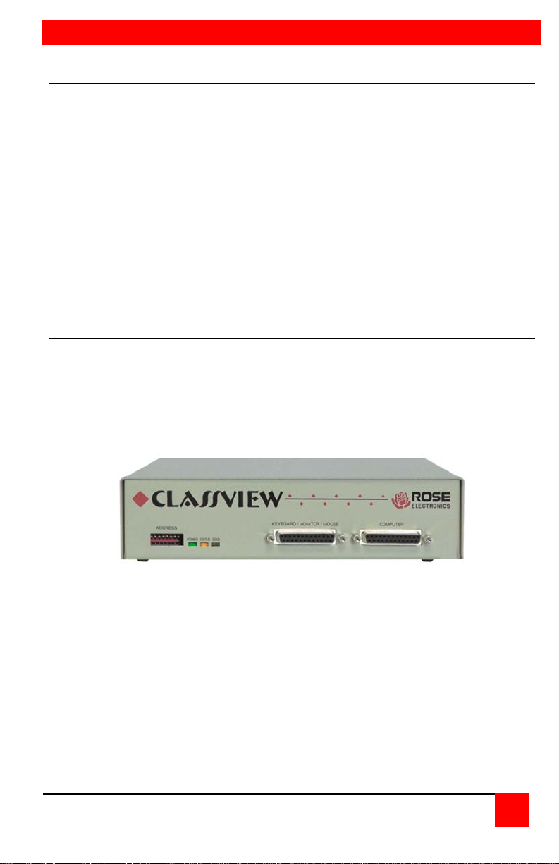
Figure 1. ClassView unit (Front view) .............................................................. 1
Figure 2. Front panel, model # CVT-CMB ....................................................... 4
Figure 3. Rear panel, model #CVT-CMB......................................................... 5
Figure 4. Connecting CPUs, keyboard, monitor, and mouse .......................... 6
Figure 5. Connecting the bus .......................................................................... 6
Figure 6. Keyboard template ........................................................................... 9
Tables
Table 1. The front panel................................................................................... 4
Table 2. The rear panel ................................................................................... 5
Table 3. Typematic rate ................................................................................. 15
Table 4. Typematic delay............................................................................... 15
Table 5. Video distance capability ................................................................. 17
Appendices
Appendix A. Cable pinout information ........................................................... 26
Appendix B. CPU/KB-Monitor-Mouse pinout ................................................. 28
Appendix C. Factory default settings ............................................................. 29
Appendix D. Dip switch description ............................................................... 29
Appendix E. General specifications ............................................................... 30
Appendix F. Cable part numbers ................................................................... 30
Appendix G. Accessories part numbers ........................................................ 30
INTRODUCTION
Disclaimer
While every precaution has been taken in the preparation of this manual, the
manufacturer assumes no responsibility for errors or omissions. Neither
does the manufacturer assume any liability for damages resulting from the
use of the information contained herein. The manufacturer reserves the right
to change the specifications, functions, or circuitry of the product without
notice.
The manufacturer cannot accept liability for damages due to misuse of the
product or other circumstances outside the manufacturer’s control. The
manufacturer will not be responsible for any loss, damage, or injury arising
directly or indirectly from the use of this product.
System introduction
Thank you for choosing ClassView™. Designed for plug and play operation,
your new ClassV ie w wi ll s i mplify your job by helping you organ i ze your
multiple computer applications. ClassView is especially designed for
classroom applications. It allows the instructor to view, share, or control
student's workstations.
Figure 1. ClassView unit (Front view)
CLASSVIEW INSTALLATION AND OPERATINS MANUAL
1

Features
Instructor can access any student's computer in three modes:
View mode – See student's station without disturbing their keyboard
or mouse
Share mode – See student's station with interactive keyboard and
mouse sharing
Control mode – See student's station with complete control over their
keyboard and mouse
Instructor can enable and disable student's computer in two modes:
Disable – Student's screen is blanked and keyboard and mouse
are locked out
Freeze – Student's screen remains on, but all keyboard and mouse
activity is locked out
Show mode allows instructors to send their screen to any or all students
Scan mode allows instructor to sequentially view each students
computer
Connect up to 255 stations
Single cable connection between units simplifies installation
Connection between units uses high quality 13W3 video connectors for
crystal clear video even at long distances
Data on bus connection uses packetized network format for fast and
highly reliable delivery of keyboard, mouse, and control information
Front panel dip switch determines port numbers and establishes network
address
Keyboard timeout feature allows sharing of CPUs
Drives video, keyboard, & mouse up to 100' away
Select CPU from keyboard or optional keypad
Video resolution supports up to 1280 x 1024
LEDs show bus status and video sending state
Screen blank function turns off video after 1 – 999 seconds of inactivity
Previous channel command for easy back and forth access to 2 CPUs
All settings can be saved in non-volatile memory
Available in 117 VAC or 230 VAC models
19" and 24" rack mount kits available
Made in USA
2
CLASSVIEW INSTALLATION AND OPERATIONS MANUAL

GETTING STARTED
To acquaint you with your ClassView unit, this manual first describes
ClassView's front and rear panels. Installation and operation instructions
begin with the Quick setup system wiring guide. This easy-to-understand
diagram illustrates how to connect ClassView to your CPUs, monitor,
keyboard, and mouse.
Package Contents
Your Class View package includes the ClassView unit, a power transformer,
this manual, and a keyboard template. Cables are generally ordered and
shipped separately.
Cable requirements
ClassView connects to a CPU with a CPU adapter cable and to the
keyboard, monitor, and mouse with a Keyboard-Monitor-Mouse ada pter
cable. These cables are most commonly purchased with the ClassView and
will provide quick and trouble-free operation. If you wish to build your own
cables, refer to the pin out information in Appendices A, B, and C. Appendix
F Describes the cable part number based on the type of equipment you wish
to connect. Appendix F lists the most common cables.
To interconnect the units together you use coax bus cables between each
box and terminators at the first unit on the bus and the last unit on the bus.
Cables and accessories are available from where you purchased your
ClassView.
Most installations use a cable for the CPU and monitor, keyboard, and
mouse which are no longer than 20 feet in length. Cable length will affect the
quality of the video, depending upon which resolution you will be using. You
can improve the video resolution and distance by ordering coax cables for
your CPU and monitor connections, see Appendix F and G and Table 6
Video Distance Capability.
Locating the unit
The ClassView unit is best located near the CPU and associated keyboard,
monitor, and mouse. This will reduce the length of the cables and provide a
more cost-effective and neater installation. The total length of bus cable
should not exceed 200 feet, depending upon the resolution of video used.
Typically you should leave the front panel accessible in order to view the
status and send signals, though once all is installed you will probably not
need to see these LEDs.
CLASSVIEW INSTALLATION AND OPERATINS MANUAL
3
FRONT PANEL
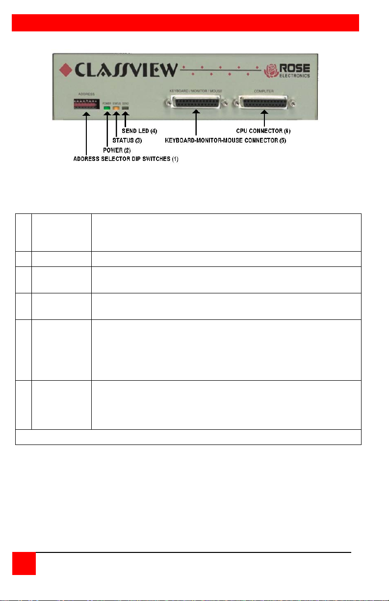
Defines the number of the CPU attached to the unit.
reserved for the instructor's unit.
2
Power LED
When lit indicates that unit is powered on.
Flashes once a second to show bus connection. Also
flashes when keyboard or mouse activity occurs.
When lit unit is sending video over the coax bus, one or
more monitors may be receiving the video.
Keyboard, monitor, and mouse are connected at this port
mouse type. Only one adapter cable is needed.*
Your computer is connected at this port using a CPU adapter
your video, keyboard, and mouse type.*
* See Appendix F and G for further cable information
Figure 2. Front panel, model # CVT-CMB
1 Address
Address 0 is reserved for diagnostics. Address 255 is
3 Status LED
4 Send LED
KeyboardMonitor-
5
Mouse
Connectors
CPU
6
Connector
using a Keyboard-Monitor-Mouse adapter cable. The cable
has a DB-25 male at one end and appropriate connectors at
the other end, depending upon your video, keyboard, and
cable. The cable has a DB25 male at one end and
appropriate connectors at the other end, depending upon
Table 1. The front panel
4
CLASSVIEW INSTALLATION AND OPERATIONS MANUAL
REAR PANEL
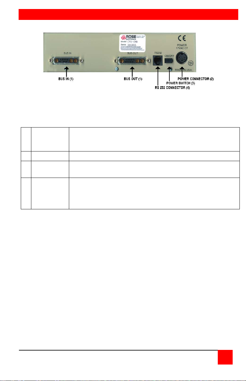
Bus cable to next unit or terminator is connected here.
n or
bus out.
2
RS232
RS232 serial port for factory diagnostics only.
Power
switch
Pressing the switch turns the unit on, provided supplied
power transformer is properly connected.
Power transformer included in package connects here. This
tap.
Figure 3. Rear panel, model #CVT-CMB
BUS in/
1
BUS out
3
4 Power
Terminator or bus cable may be connected to either bus i
is not a keyboard input. Power transformers are available for
U.S or International use. Input voltage is 17VAC with center
Table 2. The rear panel
CLASSVIEW INSTALLATION AND OPERATINS MANUAL
5
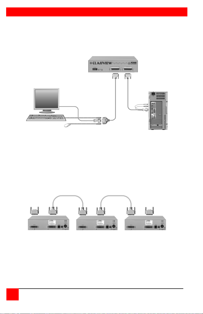
QUICK SETUP SYSTEM WIRING GUIDE
KVM Adapter Cable
CPU Adapter Cable
BUS CABLE BUS CABLE
BUS BUS
TERMINATOR TERMINATOR
The following diagrams offer a basic example of how to connect your CPUs,
keyboard, monitor, and muse and the ClassViews to one another.
Connectors will vary depending upon the types of equipment being installed.
Figure 4. Connecting CPUs, keyboard, monitor, and mouse
Figure 5. Connecting the bus
6
CLASSVIEW INSTALLATION AND OPERATIONS MANUAL

INSTALLATION
NOTE: Be sure that all computers you are connecting to your
Warning: Avoid routing cable near fluorescent lights, air
Installing the ClassView
Please refer to the safety section prior to installing ClassView. This section
provides instructions for the setup or your ClassView. For an illustrated
example, see the Quick setup system wiring guide on the previous page.
ClassView will support the monitor, keyboard, and mouse you
plan to use.
Step 1. Connecting the keyboard, monitor, and mouse
The Keyboard-Monitor-Mouse adapter cable connects your keyboard,
monitor, and mouse equipment to the ClassView. Various styles of electrical
connectors are used by different classes of equipment, so you should have
the correct cable to match your equipment's connectors. Adapter cables are
available where you purchased your ClassView. Should you prefer to build
your own cables, however, pin out information is shown in Appendices A & B.
1.1 Plug the DB-25 male connector of the adapter cable into the connector
labeled "Keyboard/Monitor/Mouse" on the ClassView front panel.
1.2 Plug the adapter cable's keyboard, monitor, and mouse connectors into
your equipment's corresponding connectors.
Step 2. Connecting the CPU
A CPU adapter cable connects your computer to the ClassView. CPU
adapter cables are available where you purchased your ClassView. Should
you prefer to build your own cable, pin out information is shown in
Appendices A and B.
2.1 Plug the DB-25 male connector of the CPU adapter cable into the
connector labeled "Computer" on the ClassView front panel.
2.2 Plug the CPU adapter cable's monitor, keyboard, and mouse connectors
into the CPU's corresponding ports.
conditioning compressors, or machines that may create electrical
noise. For best qual it y video, when exc ee di ng 20 feet use coax
cable. See Table 6 Video Distance Capability and Appendix F
and G for further cable information.
CLASSVIEW INSTALLATION AND OPERATINS MANUAL
7

Step 3. Connecting the bus
3.1 Connect the units together with the coax bus cables by connecting either
bus in or out to either bus in or bus out of the next unit.
3.2 Install terminators on the first unit on the bus and the last unit on the bus.
3.3 Set the dip switch address to identify the CPU numbers. The teacher's
station must be set to address 255. The students are usually set to start
with address 1, the next would be 2 and so on. See Appendix D for
further dip switch information.
Step 4. Powering up the system
4.1 Plug in the power transformer's power jack into the power plug located
on the back of the ClassView unit, then plug the transformer into a
power strip or wall outlet.
4.2 Push the On/Off switch on the back of the ClassView to power it up.
4.3 Upon power-up the yellow status light will light briefly and go out. After a
few seconds the status light will flash irregularly as it talks to the
keyboard and mouse attached. Then if other units are on the bus, the
LED will flash at a stead one second interval. Fi it flashes at a faster
rate, about 3/second, this indicates either a hardware error or a duplicate
address. See the troubleshooting section for more information.
4.4 Boot up the CPUs. ClassView emulates all keyboard and mouse
functions for automatic boot-up. You do not have to re-boot a CPU, if it
is inconvenient. In this case you may need to issue the mode command,
see page 15 to have proper keyboard communication.
Step 5. Testing the installation
Your ClassView is now ready for operation using its default settings. To take
full advantage of the ClassView features, refer to the Operation section
beginning on page 10. The Operation section gives detailed information
about each of the ClassView commands, describing its application and giving
the keyboard command sequence. For your convenience, this information is
summarized in the keyboard commands summary on page 19. To begin
switching immediately, however, use the following instructions.
5.1 Locate the keyboard template provided with the unit. Put it on the upper
function keys of your keyboard. The template has commands at the top
and station numbers at the bottom. Commands are carried out by
pressing and releasing the left control key, hitting the function key
corresponding to the command desired, and hitting another function key
corresponding to the station(s) to which the function will apply.
8
CLASSVIEW INSTALLATION AND OPERATIONS MANUAL

NOTE: Before entering any ClassView keyboard command, you
5.2 For example:
To view the screen of student #2;
Press and release the left control key, hit view (F1) and hit 2 (F2).
To share the CPU of student #1;
Press and release the left control key, hit share (F2) and 1 (F1).
To disable all student's screens;
Press and release the left control key, hit disable (F6) and All (F12).
To show the instructor's screen to student #3;
Press and release the left control key, hit show (F4) and hit 3 (F3)
Figure 6. Keyboard template
must press and release the left Control key. This activates
ClassView to look for commands from the keyboard. You then
have two seconds in which to start entering a valid command.
NOTE: When entering numeric commands, use only the
numeral keys located at the top of the alpha-numeric keyboard.
Numbers entered from the numeric keypad to the right will not
be recognized as valid commands.
CLASSVIEW INSTALLATION AND OPERATINS MANUAL
9

OPERATION
IMPORTANT OPERATION NOTE: To send ClassView keyboard
Operating the ClassView
ClassView is simple to operate. Port selection and function commands are
entered from the keyboard. This section details each ClassView function.
Also see the Keyboard command summary.
All commands apply only to the teacher's station. No commands can
be entered from a student station.
commands, you must first press and release the left Control key
([Ctrl]). Pressing and releasing [Ctrl] activates ClassView to look for
commands from the keyboard. You have two seconds between each
keystroke to enter a valid command, otherwise ClassView aborts the
command.
NOTE: When entering numeric commands from the keyboard, use
only the numeric keys located at the top of your keyboard. Numbers
entered from the numeric keypad on the right of the keyboard will not
be recognized as valid commands.
NOTE: ClassView commands ignore case. All command letters are
shown capitalized for clarity only. Don't use the shift key though.
NOTE: All non-switching commands which require a numeric operand
must use the [Enter] key to complete the command.
NOTE: The CPU number may be entered as a function key or as a
numeric value. The numeric value is required if there are more than
10 ports in the system.
View command
The view command is used to observe a student's screen. The command is
issued b pressing and releasing the control key, hitting the F1 key, and then
hitting a CPU number (see Note). All keyboard and mouse data will be
discarded when this mode is entered. Hitting view with an operand of All
(F12) will enable the scan mode. Hitting view with an operand of Me (F11)
will restore normal connection of the instructor back to their own CPU.
10
CLASSVIEW INSTALLATION AND OPERATIONS MANUAL

Share command
The share command is used to interact with a student. The command is
issued by pressing and releasing the control key, hitting the F2 key, and then
hitting a CPU number (See Note). All keyboard and mouse data is shared
according to the keyboard timeout setting. If the student is currently using
the keyboard and mouse when first switched to, the student will retain
control. After two seconds of inactivity the instructor can gain control. The
instructor will retain control until there is no keyboard or mouse activity for the
period of the keyboard timeout setting. Hitting share with an operand of ALL
(F12) will enable the scan mode. Hitting share with an operand of ME (F11)
will restore normal connection of the instructor's keyboard and mouse back
to their own CPU.
Control command
The control command is used to gain full control of a student's computer.
The command is issued by pressing and releasing the control key, hitting the
F3 key, and then hitting a CPU number (See Note). The student's keyboard
and mouse will be locked out and the instructor will have exclusive use of the
student's CPU. Hitting control with an operand of ME (F11) will restore
normal connection of the instructor's keyboard and mouse back to their
own CPU.
Show command
The show command is used to show the instructor's screen to any or all
students. The command is issued by pressing and releasing the control key,
hitting the F4 key, and then hitting a CPU number (See Note). The teacher
will retain control of their own CPU. The student's keyboard and mouse will
be locked out. Hitting show with an operand of All (F12) will send the
teacher's screen to all students. Hitting show with an operand of ME (F11)
will restore normal connection of the instructor's keyboard and mouse back
to their own CPU.
Enable command
The enable command restores any or all student's CPUs to the normal mode
of being connected to their own CPU. The command is issued by pressing
and releasing the control key, hitting the F5 key, and then hitting a CPU
number (See Note). Hitting enable with an operand of All (F12) will restore
all students' CPUs.
Disable command
The disable command blanks any or all student's screens and locks their
keyboard and mouse. The command is issued by pressing and releasing the
control key, hitting the F6 key, and then hitting a CPU number (See Note).
Hitting disable with an operand of All (F12) will disable all students CPUs.
Hitting disable with an operand of Me (F11) will have no effect.
CLASSVIEW INSTALLATION AND OPERATINS MANUAL
11

Freeze command
The freeze command keeps the students screen active but locks their
keyboard and mouse. The command is issued by pressing and releasing the
control key, hitting the F7 key, and then hitting a CPU number (See NOTE).
Hitting freeze with an operand of All (F12) will freeze all students' CPUs.
Hitting freeze with an operand of Me (f11) will have no effect.
Entering station numbers by numeric value
When entering a numeric value of a station number there are certain rules on
how to properly do it. After you press and release you keyboard's left control
key ([Ctrl]), and then enter the command desired, type in the port number as
described below. Remember to use the numbers located at the top of our
keyboard. Do not use the numeric keypad. The maximum scan port is also
used to determine the number of keys required to enter a port number. If the
maximum scan port is set to 99 or less, then only two digits are required to
enter the port number. If the maximum scan port is set to 100 or greater,
then three digits are required to enter the port number to select.
16 – 99 Ports: ClassView will execute the command on the desired station
when you enter the two-digit number. For single-digit ports, you can enter
the number with a leading zero (such as 01) or enter the single-digit number
and press [Enter]. If you enter only one digit, and do not follow it with
[Enter], ClassView will wait two seconds for you to enter another digit, then,
if no additional number is entered, will execute the command on the singledigit port.
100 – 256 Ports: ClassView will execute the command on the desired station
when you enter the three-digit number. For single-and-double-digit ports,
you can enter the number with one or two leading zeros (such as 027 or
001), or enter the single-or-double-digit number and press [Enter]. As noted
above, ClassView will wait two seconds for a second or third number to be
entered, then will execute the command on the port number entered.
Going to the next highest or lowest port
From the keyboard you can switch forward or backward through the CPUs by
using the + and – keys. To go to the numerically next higher port, press and
release the left control key ([Ctrl]), then press the "+ /-" (plus) key. To go to
the next numerically lower port, press and release ([Ctrl]), then press the '+/" (minus) key. The command is not case sensitive. Use the keys at the top
of your keyboard, not those on the numeric pad.
The count wraps around. If follows the ports as defined by the scan
minimum and maximum settings, described later.
12
CLASSVIEW INSTALLATION AND OPERATIONS MANUAL

Keyboard timeout command
This is a very powerful feature that controls when two or more keyboards are
sharing a CPU. The setting of this interval value determines after what
amount of time a CPU becomes available for use by another keyboard.
This value is loaded upon connecting to a CPU and when any keyboard or
mouse activity occurs. If there is no keyboard or mouse activity for this time
interval the CPU is available for connection by another port. Each ClassView
unit can have a different timeout value set. If another keyboard connects to a
CPU on a particular unit, the timeout is set by that remote keyboard and not
the local one.
If the timeout is set for zero this is an instant timeout. Two keyboards each
set for a zero timeout and connected to the same CPU will appear to both be
connected to the CPU. If the timeout is set for 255 this is an infinite timeout.
A CPU will not be released, until another port is switched to from the
keyboard with the infinite timeout or the timeout is changed.
The default setting is 2 seconds. To set another interval, press and release
the left Control Key, type "H", enter the new keyboard timeout interval (in
seconds), and press [Enter]. Remember to use the upper numeric keys, not
the numeric keypad to the right. Follow with the Keep command to save the
setting. All student stations have a timeout of 2 seconds.
Previous port command
This setting is intended to provide a convenient method to alternate between
two CPUs. You can rapidly and easily switch to the previous port that you
were on. This especially useful when you have many CPUs and entering the
multi-digit-port number can be tedious. To set another interval, press and
release the left Control Key and then press the "Backspace" key.
Scan mode commands
To enable scanning from the keyboard, press and release the left Control
Key, then type "S". ClassView will begin scanning sequentially from its
current port through the remaining ports up to the maximum scan port and
begin again at the minimum scan port. The time between switching to the
next higher port is the scan time interval (see below) and is programmable
from 1 – 15 seconds.
To stop scanning, press and release the left Control Key, then type "X".
Scanning is also disabled by entering a port selection command. You can
program the unit to start scanning upon power-up by enabling the scan mode
and issuing the keep command.
Scan time interval command
The scan time interval command sets the time, in seconds, that ClassView
will pause at each of the ports when scanning. The allowable scan time is
from 1 to 15 seconds. The default setting is 5 seconds. To set another time
interval, press and release the left Control Key, type "I", enter the new scan
time interval (in seconds), and press [Enter].
CLASSVIEW INSTALLATION AND OPERATINS MANUAL
13

Minimum / maximum scan port commands
The scan minimum and maximum port commands set the range of ports for
which scanning occurs. The default minimum port is 1, the default maximum
port is 16. To set the minimum scan port, press and release the left Control
Key, type "<", enter the new minimum scan port and press [Enter]. To set
the maximum scan port, press and release the left Control Key, type ">",
enter the new maximum scan port and press [Enter].
The maximum scan port is also used to determine the number of keys
required to enter a port number. If the maximum scan port is set to 99 or
less, then only two digits are required to enter the port number. If the
maximum scan port is set to 100 or greater, then three digits are required to
enter the port number to select.
Screen blanking command
This feature reduces the wear on your screen and provides security for your
system by blanking the screen when there has been no keyboard or mouse
activity for a specified length of time. To set the screen blank interval time,
press and release the left Control key, type "V", enter the interval time in
seconds (0 – 999), and press [Enter] (an interval time of 0 disables this
screen blank feature). Follow with the Keep command to save the new
setting in the unit's non-volatile memory.
When in the Screen Blank state, all ClassView select LEDs will be off. To
restore the video screen, press any key or move the mouse. To disable the
screen blank feature, press and release the left Control Key, type "V", enter
"0" as the interval time, and press [Enter]. Follow with the Keep command if
desired to save it.
Mode command
ClassView supports keyboard modes 1, 2, and 3. the keyboard mode is set
by commands from the CPU. Mode 2 is the most common mode and is also
the power-up state of all 101 type and PS/2 keyboards. Mode 1 is used
primarily by most models of the latest PS/2s. Mode 3 is used by certain
specialized servers.
ClassView automatically detects a CPU's keyboard mode upon CPU boot-up
and thus learns which mode the CPU uses. If the CPU has already booted
and is then connected, ClassView cannot detect the CPU's keyboard mode
and uses the setting stored in the ClassView's non-volatile memory. The
mode command can be issued to change the keyboard mode for any port
and can be saved in non-volatile memory with the Keep command. If a port
was previously set to mode 1 and you connect a mode 2 CPU to that port, it
probably will not communicate correctly and you will need to issue the mode
command.
To issue the Mode command, press and release the left Control Key, type
"M", and enter the mode number "1", "2", or "3" followed by [Enter]. Follow
with the Keep command. To change the mode on another port, you must
first switch to that port and then issue the mode command.
14
CLASSVIEW INSTALLATION AND OPERATIONS MANUAL

Rate
Keys/sec
Rate
Value
Rate
Keys/sec
Rate
Value
Rate
Keys/sec
Rate
Value
Rate
Keys/sec
Rate
Value
30.0
0
15.0 8 7.5
16
3.7
24
26.7
1
13.3 9 6.7
17
3.3
25
24.0
2
12.0
10
8.0
18
3.0
26
21.8
3
10.9
11
5.5
19
2.7
27
20.0
4
10.0
12
5.0
20
2.5
28
18.5
5
9.2
13
4.6
21
2.3
29
17.1
6
8.6
14
4.3
22
2.1
30
16.0
7
8.0
15
4.0
23
20.
31
Delay
Value
Delay
Value
Delay
Value
Delay
Value
250 0 500
32
750
64
1000
96
Typematic value command
ClassView can be configured to control the keyboard typematic rate and
delay. This setting is used to adjust the user preference of the way the
keyboard acts when holding a key down to repeat the key, such as when
moving a cursor across a line. The rate is the speed at which the keys are
sent in keys/second. The delay is the wait time in milliseconds after the key
is initially pressed, before additional keystrokes are sent. To issue the
command press and release the left Control Key, then type "A", then enter
the 1-3 digit decimal typematic value followed by {Enter]. The typematic
value is defined as shown in the below table. Use the Keep command to
save the value.
The typematic value to be used is determined by using the equation:
Typematic Value = Rate value + Delay value. Pick the desired rate in
keys/sec. (32 choices) and delay in milliseconds (4 choices) from the below
table. Add the values to the right of the desired settings. For example to use
a Rate of 16.0 keys/sec, and a 500 millisecond delay, the typematic value
would be 7 + 32 =39, so to set this value, type Ctrl A, 39 {Enter}.
Keep command
The Keep command saves the current state of the ClassView's custom
settings. These settings are scan state upon power up, scan time interval,
scan minimum and maximum ports, screen blank time interval, CPU mode,
and keyboard LED state, keyboard timeout interval, and the keyboard
typematic value. These settings are saved in non-volatile memory and
become the power-up settings. To enter the command, press and release
the left Control Key, then press "K",
Table 3. Typematic rate
Table 4. Typematic delay
CLASSVIEW INSTALLATION AND OPERATINS MANUAL
15

Null command
This command is used to re-synchronize an out-of-sync PS/2 mouse. Such
a condition can result due to transients, spurious power-up effects, or
plugging and unplugging of cables with live equipment. The command may
need to be entered once or twice, depending if the mouse is out-of-sync by
one or two bytes. Microsoft mouse driver version 9.01 corrects this
inadequacy of previous drivers and renders this command unnecessary. At
publishing time, it is believed this mouse driver is only available for DOS and
Window. To issue the command, press and release the left Control Key,
they type "N".
Rom identification command
This command is used to identify the revision level of ClassView firmware
currently installed. Before entering this command, your currently selected
CPU should be at a command prompt, so that when the ClassView sends the
ROM revision level that the results will be displayed. To issue the command,
press and release the left Control Key, then type "I", ClassView will send
back its current firmware revision level, in the format majorlevel, minorlevel.
Reset command
This command is used to re-boot the mouse and keyboard without removing
power from the ClassView. This is most useful to reset a PS/2 mouse which
has been unplugged and plugged back in. This command is also useful to
enable mouse data to be sent to a CPU which has not enabled the mouse.
This may be the case if the ClassView was not connected or powered off
after a CPU was booted up. To issue the command, press and release the
left Control Key, then type "R". This command should not be issued to a
CPU which has a PS/2 muse connected, but no mouse driver is loaded,
since many CPUs will crash if you send them unexpected mouse data.
16
CLASSVIEW INSTALLATION AND OPERATIONS MANUAL

5'
10'
20'
30'
50'
75'
100'
125'
150'
200'
640X480
60 Hz refresh
N4
C4
N4
C4
N4
C4
N4
C4 C4 C4 C4 C4 C3 C3
640x480
72-75Hz refresh
N4
C4
N4
C4
N4
C4
N3
C4 C4 C4 C4 C3 C3 C3
800x600
non-interlaced
N4
C4
N4
C4
N3
C4
N3
C4 C4 C4 C4 C3 C3 C3
1024x768
interlaced
N4
C4
N3
C4
N3
C4
N3
C4 C4 C4 C3 C3 C3 C3
1024x768
non-interlaced
N4
C4
N3
C4
N3
C4
N3
C4 C4 C3 C3 C3 C3
1280x1024
interlaced
N3
C4 C4 C3 C3 C3 C3
1280x1024
non-interlaced
N3
C4 C4 C3 C3
Video distance capability
The limitation on driving distance is usually due to the quality of the video.
The table below shows the distances, resolution, and quality of video that
can be expected. The table uses a letter which shows the cable type and a
number which refers to the quality of the video, as described below. This
table applies to the base unit without chaining. There will be some
degradation when ClassViews are chained together. Rose Electronics does
not support systems where the video quality is 1 or 2. There are further
capabilities not listed here in order to send the higher resolution video longer
distances. Please contact Rose Electronics technical support for more
details.
N – Normal cabling
C – Coax cabling
4 – Perfect or near perfect; unable to easily detect defects in screen
3 – Very acceptable; images clear, small reflections around lettering
depending upon color; if you examine the screen closely you will
find defects
2- Acceptable; slightly fuzzy images; readable text, acceptable for casual
use, but not for prolonged viewing as this will cause eye fatigue
1- Unusable; images smeared, text not easily readable
Table 5. Video distance capability
CLASSVIEW INSTALLATION AND OPERATINS MANUAL
17

Power interruption to the ClassView
Certain keyboards are sensitive to rapid cycling of the power. Since power to
the keyboard is provided from the ClassView, you should not interrupt power
to the ClassView for less than three seconds. The ClassView is immune to
such transients, but the keyboard may not reset correctly.
Rackmount kit
The Rackmount kit is an optional item that can be ordered at any time. Your
ClassView unit is pre-drilled to accept the rack-mounting screws. There are
two sized available, 19" x 5.25" and 24" by 5.25".
Keyboard commands
To enter a keyboard command, first press and release the left Control Key,
represented by [Ctrl]. Then enter the command followed by ay parameters
you wish to specify, for example the port number. Letter/symbol commands
are not case sensitive, and are shown in upper case for clarity only. Do not
use the shift key when entering a command. Do not use the numeric keypad
to enter any commands.
All ClassView commands use a two second time-out between characters, to
abort the command. This is a feature that restores the keyboard to normal
operation, so the keyboard is not put into a command mode which might lock
it up from normal operation. The [Ctrl] character is not passed through to the
CPU when it is pressed and released. The command characters and
command operands are absorbed by the ClassView and not sent to the CPU.
All non-switching commands which require a numeric operand must use the
[Enter] key to complete the command.
Refer to Table 7 for a complete list of all available keyboard commands.
18
CLASSVIEW INSTALLATION AND OPERATIONS MANUAL

KEYBOARD COMMAND SUMM ARY
Command
Key Sequence
Description
View
[Ctrl] F1 station #*
View student's station
Share
[Ctrl] F2 station #*
Share student's station
Control
[Ctrl] F3 station #*
Control student's station
Show
[Ctrl] F4 station #*
Show instructors screen to students
Enable
[Ctrl] F5 station #*
Enable keyboard, mouse, and monitor at
student's station
Disable
[Ctrl] F6 station #*
Disable keyboard, monitor, and mouse to
the selected CPU port
Freeze
[Ctrl] F7 station #*
Disables keyboard and mouse at student's
station
Go to selected port
[Ctrl] xxx
digits)
Connects your keyboard, monitor, and
Go to next higher port
[Ctrl] +
Selects the next higher sequential port
Go to next lower port
[Ctrl] -
Selects the next lower sequential port
Scan On
[Ctrl] S
Turns Scan mode on, causing ClassView to
up the unit will start scanning.
Scan Off
[Ctrl] X
Turns Scan mode off. Scan can also be
command
Scan time interval
[Ctrl] T xx [Enter]
secs)
Sets the time, in seconds, that ClassView
g
Minimum scan port
[Ctrl] < xxx [Enter]
Sets port number which is the lowest port
ached, the next port will
Note: Follow with keep command
Maximum scan port
[Ctrl] > xxx [Enter]
Sets port number which is the highest port
l
Note: Follow with keep command
Previous port
[Ctrl] BS (backspace)
Switches to the previous port you were on
Keyboard Command Summary
xxx=port number (1-3
xx=time in sec. (1-15
where xxx = port
number
where xxx = port
number
mouse to the selected CPU port
start scanning sequentially from the current
port through the remaining ports until scan
max is reached and then switching to scan
min. If local only is enabled then scanning
is local port 1-16 only. If scan is on when a
Keep command is issued then upon power
stopped by entering a port selection
will pause at each port when scannin
for scanning. When scanning and
maximum scan is re
be minimum scan.
for scanning. When scanning and
maximum scan is reached, the next port wil
be minimum scan.
CLASSVIEW INSTALLATION AND OPERATINS MANUAL
19

Command
Key Sequence
Description
Keyboard timeout
[Ctrl] H xxx [Enter]
Determines after what amount of time
Note: follow with keep command
Reset command
[Ctrl] R
Resets and enables mouse and
currently selected port
Send null to mouse
[Ctrl] N
Used to re-synchronize PS/2 mouse
which has gotten out-of-sync
Identify ROM version
[Ctrl] i
Identifies ROM version, CPU must be
at a command prompt to receive value
Keep settings
[Ctrl] K
Tells ClassView to save custom
settings of various commands
Set screen blank time
[Ctrl] V xxx [Enter]
Sets time in seconds with no keyboard
Note: Follow with keep command
Set keyboard mode
Select port, ten enter
Sets ClassView CPU's keyboard
Note: Follow with keep command
Set typematic value
[Ctrl] A xxx [Enter]
Sets power-on keyboard typematic
Note: Follow with keep command
Keyboard command summary (continued)
interval
where xxx = time in
seconds
(0 – 255 seconds)
where xxx = time in
seconds
(0 – 999 seconds)
command:
[Ctrl] M x [Enter]
where x = 1, 2, or 3
where xxx is a number
from 0 to 127 indicating
Keyboard typematic
value
a CPU becomes available for access
by another keyboard. Value of 255 is
infinite timeout. Value of 0 is instant
timeout.
keyboard, enables PS/2 mouse on
or mouse activity after which video will
be turned off. Video is turned back on
when any key is pressed or mouse is
moved.
mode. Will change the keyboard to
the new mode and update its internal
value. Switching to this port will se the
new mode.
action which is controlled by the
ClassView. This can be used to adjust
the key stroke rate and delay to the
user preferred settings. See Tables 4
and 5 for how the typematic value is
determined.
* Station # can be either F1-F10 to mean student 1-10, F11 to mean the
instructor's CPU, F12 to mean all students, or a two-digit or three digit
numeric value corresponding to the student's station number. The number of
digits to enter is determined by the maximum scan port. If the maximum
scan port is set <9 only one digit is necessary. If the maximum scan port is
set to <99 then two digits are needed. If the maximum scan port is set >99
then three digits are required.
20
CLASSVIEW INSTALLATION AND OPERATIONS MANUAL

TROUBLESHOOTING
ClassView troubleshooting guide
1. CPU does not boot, keyboard error received
CPU does not boot, mouse error received
a. Cable is loose, reseat cable and hit F1 to continue or reboot
computer
b. Wrong cable plugged in, keyboard and mouse cables reversed
c. Cable is defective, try using cable from another CPU. If problem goes
away cable is defective
d. Port on ClassView is defective, try using another port on ClassView.
If problem goes away port is defective
e. Port on CPU is defective, try plugging in keyboard or mouse directly
if problem remains CPU port is defective. If CPU power status LED
not lit, fuse on motherboard ma be blown
2. Mouse drives does not load
a. If PS/2 type mouse, CPU must be connected to ClassView or mouse
at boo-up time in order for muse to be recognized by CPU. Reboot
computer with ClassView powered on and cable attached
b. If RS-232 type mouse, make sure right COM port is being used and
syntax of mouse driver is correct to search for the correct port
c. Incompatible or old mouse driver being used, try latest driver. At
time of this publishing Microsoft 9.01 driver is best one available
3. Can't switch ports from keyboard
a. Power to ClassView was removed for less than three seconds
possibly causing keyboard to lock up. Disconnect keyboard and plug
it back in
b. The mode of the keyboard does not match that of the CPU. Issue
the mode command, usually 1 for IBM PS/2's and 2 for all others.
The default setting of the ClassView is mode 2. Sometimes an
incorrect mode will confuse the CPU or keyboard and require re-
booting the CPU or resetting the keyboard by unplugging and
plugging it back in
c. If try to reach a remote port, that port is busy. Try again later
d. If trying to reach a remote port, the bus cable is disconnected, or the
remote box is powered off. Check status LED on local unit, if it is not
flashing at a one-second interval then bus cable has been
disconnected or no other units are attached to the network. Check
remote unit for activity also.
e. KB port or CPU port cable disconnected. Typing in characters to the
KB should cause the status LED to flash more rapidly. Use this to
test if you have a good KB or mouse connection to the unit
CLASSVIEW INSTALLATION AND OPERATINS MANUAL
21

4. Wrong or missing characters from tho se typed
a. The keyboard mode is incorrect. See item 3c above
5. Can't access all functions of mouse
a. If Microsoft BallPoint mouse, get latest Microsoft revision 9.01 driver
6. Mouse does not move
a. ClassView turned off after or not connected when CPU booted or
application using mouse run. Exit and re-enter application using
mouse or issue reset command
b. PS/2 mouse was not connected when ClassView powered up or has
been disconnected and reconnected. Issue the reset command
7. PS/2 mouse gets out of sync
a. Cabling was disturbed during mouse movement. Issue the null
command once or twice to re-sync the mouse. Get a later mouse
driver which does not exhibit this problem, such s Microsoft rev 9.01
8. Video fuzzy
a. Cable too long or wrong type. Verify that resolution and distance
match Video Distance Capability table. Upgrade cable if necessary
9. Video not synchronized or wrong color
a. Cable is loose, reseat cable
b. Wrong CPU cable used. If you have a 9515, 9517, 9518, XGA mono
or similar monitor, you must use special cables or adapters. See
previous section, XGA video, model 9515, 9517, 9518 monitors
c. Cable is defective, try using cable from another CPU if problem goes
away cable is defective
d. Port on ClassView is defective, try using another port on ClassView.
If problem goes away port is defective
10. Lower resolution video OK, but can't enter high resolution mode
a. Wrong CPU cable used. If you have a XGA, XGA-2, or other high
resolution video card you should probably be using the CAB-Y…
cable to connect your CPUs
b. Driver has not been setup. Windows, OS/2, or other driver has not
been configured for this resolution. Configure the driver
11. Status LED flashes at steady 3/second rate, unit does not respond
a. Duplicate address is present. Some other ;unit has same address as
this unit. Change address from DIP switch and power unit off an on
b. Unit has a defective component and fails self test. Unit must be
serviced.
22
CLASSVIEW INSTALLATION AND OPERATIONS MANUAL

SERVICE INFORMATION
Maintenance and repair
This unit does not contain any internal user-serviceable parts. In the event a
unit needs repair or maintenance, you must first obtain a Return
Authorization (RA) number from Rose Electronics or an authorized repair
center. This Return Authorization number must appear on the outside of the
shipping container. See Limited Warranty for more information.
When returning a Unit, it should be double-packed in the original container or
equivalent, insured and shipped to:
Rose Electronics
Attn: RA__________
10707 Stancliff Road
Houston, Texas 77099 USA
Technical support
If you are experiencing problems, or need assistance in setting up,
configuring or operating your ClassView, consult the appropriate sections of
this manual. If, however, you require additional information or assistance,
please contact the Rose Electronics Technical Support Department at:
Phone: (281) 933-7673
E-Mail: TechSupport@rose.com
Web: www.rose.com
Technical Support hours are from: 8:00 am to 6:00 pm CST (USA), Monday
through Friday.
Please report any malfunctions in the operation of this unit or any
discrepancies in this manual to the Rose Electronics Technical Support
Department.
CLASSVIEW INSTALLATION AND OPERATINS MANUAL
23

SAFETY
Safety
This ClassView has been tested for conformance to safety regulations and
requirements, and has been certified for international use. Like all electronic
equipment, the ClassView should be used with care. To protect yourself
from possible injury and to minimize the risk of damage to this Unit, read and
follow these safety instructions.
Follow all instructions and warnings marked on this Unit.
Do not attempt to service this Unit yourself.
Do not use this Unit near water.
Assure that the placement of this Unit is on a stable surface or rack
mounted.
Provide proper ventilation and air circulation.
Keep the power cord and the connection cables clear of obstructions that
might cause damage to them.
Use only the power cords, power transformer and connection cables
designed for this Unit.
Use only a grounded (three-wire) electrical outlet.
Keep objects that might damage this Unit and liquids that may spill, clear
from this Unit. Liquids and foreign objects might come in contact with
voltage points that could create a risk of fire or electrical shock.
Operate this unit only when the cover is in place.
Do not use liquid or aerosol cleaners to clean this Unit. Always unplug
this Unit from its electrical outlet before cleaning.
Unplug this Unit from the electrical outlet and refer servicing to a
qualified service center if any of the following conditions occur:
The power cord or connection cables are damaged or frayed.
The Unit has been exposed to any liquids.
The Unit does not operate normally when all operating instructions
have been followed.
The Unit has been dropped or the case has been damaged.
The Unit exhibits a distinct change in performance, indicating a need
for service.
24
CLASSVIEW INSTALLATION AND OPERATIONS MANUAL

Safety and EMC regulatory statements
Safety Information
Documentation reference symbol. If the product is marked
with this symbol, refer to the product documentation to get
more information about the product.
WARNING A WARNING in the manual denotes a hazard that can
cause injury or death.
CAUTION A CAUTION in the manual denotes a hazard that can
damage equipment.
Do not proceed beyond a WARNING or CAUTION notice until you have
understood the hazardous conditions and have taken appropriate steps.
Grounding
These are Safety Class I products and must have an un-interruptible earth
ground from the main power source to the product’s input wiring terminals,
power cord, supplied power cord set, or chassis. Whenever it is likely that the
protection has been impaired, disconnect the power cord until the ground has
been restored.
Servicing
There are no user-serviceable parts inside these products. Only servicetrained personnel may perform any servicing, maintenance, or repair.
The user may adjust only items mentioned in this manual.
CLASSVIEW INSTALLATION AND OPERATINS MANUAL
25

APPENDICES
Pin-to Pin wiring
Keyboard-Monitor-Mouse Adapter
PS/2 Keyboard with MiniDin-6M
PS/2 Mouse with MiniDin-6M
ClassView
DB-25M
Keyboard
MiniDin-6F
ClassView
DB-25M
Mouse
MiniDin-6F
4
11
3
4
Digital Ground
+ 5V
4
11
3
4
Digital Ground
+ 5V
PC Keyboard with Din-6M
Serial Mouse with DB-9F
ClassView
DB-25M
Keyboard
DIN-5M
ClassView
DB-25M
Mouse
DB-9M
4
4
Digital Ground
23
24
5
4
Digital Ground
DTR
Serial Mouse with DB-25F
ClassView
DB-25M
Mouse
DB-25M
23
24
7
20
Digital Ground
DTR
VGA Monitor with HD-15M
ClassView
DB-25M
Monitor
HD-15F
1,2,3
6,7,8
Analog Ground
Appendix A. Cable pinout information
You can, if you prefer, build your own adapter cables. The following tables
give you all pertinent information for cable construction.
7
8
7
8
11
KVM adapter Cable
Mouse – DB9M
Video – HD15F
Keyboard – Din-5F
Signals
5
1
1
2
5
Keyboard Clock
Keyboard Data
Signals
Keyboard Clock
Keyboard Data
+5V
Mouse
Video
KBD
DB25M
10
21
12
13
21
12
13
14
15
16
9
4
5
6
5
1
3
2
7
2
3
4
5,10
13
14
1
2
3
Signals
Mouse Clock
Mouse Data
Signals
TxD
RxD
RTS
Signals
TxD
RxD
RTS
Signals
Digital Ground
Hor. Sync
Vert. Sync
Red
Green
Blue
26
CLASSVIEW INSTALLATION AND OPERATIONS MANUAL

Pin-to Pin wiring
CPU Adapter
PS/2 Keyboard port with MiniDin-6F
PS/2 Mouse port with MiniDin-6F
ClassView
DB-25M
Keyboard
MiniDin-6M
Signals
ClassView
DB-25M
Mouse
MiniDin-6M
4
11
3
4
Digital Ground
+ 5V
4
11
3
4
Digital Ground
+ 5V
CPU Keyboard port with Din-5F
Serial Mouse port with DB-9M
ClassView
DB-25M
Keyboard
DIN-5M
ClassView
DB-25M
Mouse
DB-9M
4
11
4
5
Digital Ground
+5V
23
5
Digital Ground
Serial Mouse port with DB-25M
ClassView
DB-25M
Mouse
DB-25M
23
13
7
4
Digital Ground
RTS
VGA Video port with HD-15F
ClassView
DB-25M
Monitor
HD-15M
1,2,3
16
6,7,8
3
Analog Ground
Blue
Signals
7
8
7
8
CPU adapter cable
Mouse – DB9F
Video – HD15F
Keyboard – Din5M
5
1
1
2
Keyboard Clock
Keyboard Data
Signals
Keyboard Clock
Keyboard Data
Mouse
Video
KBD
DB25M
10
12
13
12
14
15
9
4
5
6
5
1
2
7
3
5,10
13
14
1
2
Mouse Clock
Mouse Data
Signals
RxD
RTS
Signals
RxD
Signals
Digital Ground
Hor. Sync
Vert. Sync
Red
Green
CLASSVIEW INSTALLATION AND OPERATINS MANUAL
27

Pinouts for ClassView
DB-25 Female Connectors
Keyboard-
Mouse Port
1
5
Ground
HSync-in
Ground
HSync-out
Analog Ground
Video Control
6
10
VSync-in
MSData
VSync-out
MSData
Video Control
Mouse Data
11
13
+5V-in
RS232-RTS
+5V-out
RS232-RTS
Power for LEDs, Peripherals
Serial Data
14
16
Red-in
Blue-in
Red-out
Blue-out
VGA Color
VGA Color
17
20
Reserved
Reserved
Reserved
Reserved
Reserved
Reserved
21
25
Reserved
RS232-RXD
Reserved
RS232-RXD
Reserved
RS232-RXD
Appendix B. CPU/KB-Monitor-Mouse pinout
Pins
2
3
4
7
8
9
12
15
Numbered
CPU Ports
Ground
Ground
Ground
KBClk
KBData
MSCLK
RS232-TXD
Green-in
DB-25 Female Connector
Monitor-
Ground
Ground
Ground
KBClk
KBData
MSCLK
RS232-TXD
Green-out
Analog Ground
Analog Ground
Digital Ground
Keyboard Clock
Keyboard Data
Mouse Timing
Serial Data
VGA Color
Description
18
19
22
23
24
Reserved
Reserved
Ground
Ground
V+
28
CLASSVIEW INSTALLATION AND OPERATIONS MANUAL
Reserved
Reserved
Ground
Ground
V+
Reserved
Reserved
Digital Ground
Digital Ground
8-10V, 10ma only

Setting
Default
Scan enable
Off
Scan time Interval
5 seconds
Scan minimum port
1 (local)
Scan Maximum port
16 (local)
Keyboard timeout
2 seconds
Caps/Numlock/Scroll
Numlock On
Keyboard mode
2
Screen Blank time Interval
0 (Off)
Typematic Value
43 (Rate=10.9chars/sec, delay = 500 millisec.)
ADDRESS
1 2 3 4 5 6 7 8
128 64 32 16 8 4 2 1
Appendix C. Factory default settings
Appendix D. Dip switch description
DIP SWITCH
POSITION
DIP SWITCH
VALUE
A Unit's address is determined from the settings of the dip switch upon power
up. The dip switch forms a standard binary number with up being a "one"
and down being a "zero". Each position has a value corresponding to it.
From left to right the values are 128, 64, 32, 16, 8, 4, 2, and 1. When the dip
switch is up add the values of the position to form the address value.
The most common values and positions are:
1 (8 up – shown above)
2 (7 up)
3 (7, 8 up)
4 (6 up)
5 (6, 8 up)
6 (6, 7 up)
7 (6, 7, 8 up)
8 (5 up)
9 (5, 8 up)
10 (5, 7 up)
CLASSVIEW INSTALLATION AND OPERATINS MANUAL
29

SIZE / WEIGHT
8.8"W x 2.25"H x 4.9"D / 3 lbs
INPUT POWER
117 VAC power adapter,
230 VAC optional
OUTPUT POWER
17 VAC CT, 700ma
POWER CONNECTOR
DIN5
CPU/KEYBOARD/MOUSE
CONNECTORS
DB25F
BUS IN/OUT CONNECTORS
13W3F
CHASSIS
Fully shielded, black painted steel
CONTROLS
Power on/off, 8 position dip switch
INDICATORS
Power LED (green) / Status LED (yellow)
Send LED (yellow)
Part Number
Description
Monitor/Keyboard/Mouse Adapter Cables
CAB-VX0509M1
VGA-AT keyboard-Serial (9) mouse to DB-25M
CAB-VX0606M1
VGA-PS/2 keyboard-PS/2 mouse to DB25M
CPU Adapter Cables
CAB-VX0509Cxx*
VGA-AT keyboard-Serial (9) mouse to DB-25M
VX0606Cxx*
VGA/XGA – PS/2 keyboard-PS/2 mouse to DB25M
CAB-C0509Cxx**
VGA/XGA Coax – AT keyboard-Serial (9) mouse to
DB-25M
CAB-C0606Cxx**
VGA/XGA Coax – PS/2 keyboard-PS/2 mouse to
DB25M
CAB-SMxx***
Coax bus cable 13W3M to 13W3M
(xx=length in feet)
* Standard lengths of 5, 10, and 20 feet
** In 30, 50, 75, 100, 125, 150, and 200 foot lengths
Part Number
Description
ACC-SMT
Bus terminator, two required per system
RM-SV16
Rackmount: kit - installation in 19-inch racks
RM-SV16/24
Rackmount: kit - installation in 24-inch racks
Appendix E. General specificatio n s
Appendix F. Cable part numbers
Appendix G. Accessories part numbers
30
CLASSVIEW INSTALLATION AND OPERATIONS MANUAL


10707 Stancliff Road Phone: (281) 933-7673
Houston, Texas 77099 WWW.ROSE.COM
 Loading...