

Page 1
X24 Projector
Original Instructions
www.rosco.com
(Revision: Feb2015)
Page 2

TABLE OF CONTENTS
Introduction ........................................................................................................................... 3
Warnings ................................................................................................................... ............. 4
Modules .................................................................................................................................. 6
Base Unit ......................................................................................................................................................... 6
Wheel Module ............................................................................................................................................... 8
Lens Module ................................................................................................................................................10
Analog Control Panel ................................................................................................................................11
Preparing for Use ................................................................................................................. 12
Installing the Lamp (Base Unit) .............................................................................................................12
Installing a Glass Pattern (Wheel Module) .......................................................................................13
Installing a Lens Barrel (Lens Accessory) ...........................................................................................14
Unit Operation (Analog, Wheel, Lens) ................................................................................ 15
Mounting .....................................................................................................................................................15
Powering Up ................................................................................................................................................15
Adjusting Brightness ...............................................................................................................................16
Adjusting Focus ..........................................................................................................................................16
Adjusting Wheel Speed and Direction ..............................................................................................16
Adjusting Shutters on the Wheel Module .........................................................................................16
DMX Control Module ........................................................................................................... 17
Dowser ...........................................................................................................................................................18
Manual Mode ..............................................................................................................................................19
DMX Mode ...................................................................................................................................................20
Troubleshooting .................................................................................................................. 22
Specifications ....................................................................................................................... 24
Mechanical Specifications ......................................................................................................................24
Electrical Specifications ...........................................................................................................................24
Wheel Module Specifications ................................................................................................................24
Lamp Specifications ..................................................................................................................................24
Lens Module Specification .....................................................................................................................24
Warranty ............................................................................................................................... 25
Certificate of Conformity .................................................................................................... 26
2
X24 PROJECTOR ORIGINAL INSTRUCTIONS
Page 3

INTRODUCTION TO YOUR X24 PROJECTOR
Congratulations on your purchase of the Rosco Laboratories X-24 Projector. (Also known as the
X-Effects).
This modular projector is intended to provide a range of unique lighting effects with high
brightness in a compact package.
These effects include, but are not limited to, light reflecting off water and fire of varying
intensities.
A variety of lenses provide a wide range of beam angles suitable for any situation. In reality, the
effects are limited only by your imagination.
www.rosco.com
3
Page 4

WARNINGS
The light beam near the front of the unit (< 1m / 3.3 ft.) is very
concentrated.
Make sure that no object or person comes into the light beam at this range as
burns or fire may result.
The top lid of the unit may become hot to the touch during operation.
Contact during or immediately following operation may result in burns.
The lamp is subject to high temperatures and pressures during operation. Do
not attempt to operate unit with lid open. Also do not attempt to handle lamp
within 1 hour of operation.
High voltages are produced when the unit attempts to strike the lamp. Only
apply power to the unit when a lamp is attached properly seated in the unit,
and the lid is closed.
High voltages and stored energy are present inside the unit. Only trained
service personnel should engage in repairs or replacements beyond the
modules or lamp.
At very cold temperatures the lamp may need to warm up close to room
temperature before it will properly strike.
The use of a safety cable is strongly recommended when hung overhead. Also
make sure not to block the top, bottom, or rear vents when mounted during
operation.
Ventilation openings are not to be obstructed during the operation of the
appliance.
This appliance is not intended for use by persons (including children) with
reduced physical, sensory or mental capabilities, or lack of experience and
knowledge, unless they have been given supervision or instruction concerning
use of the appliance by a person responsible for their safety.
Children shall be supervised to ensure that they do not play with the appliance.
4
X24 PROJECTOR ORIGINAL INSTRUCTIONS
Page 5

This appliance can be used by children aged from 8 years and above and
persons with reduced physical, sensory or mental capabilities or lack of
experience and knowledge if they have been given supervision or instruction
concerning use of the appliance in a safe way and understand the hazards
involved.
Children shall not play with the appliance.
Cleaning and user maintenance shall not be made by children without
supervision.
Disconnect The X24 from power before maintenance, servicing or replacing
parts.
Units in outdoor settings may need to be shielded from the elements and/
or heated. There are commercially available enclosures that can serve this
purpose, please call Rosco for more information. 1-800-767-2669.
www.rosco.com
5
Page 6
MODULES
Base Unit
The base unit contains the lamp, electronic ballast, and accessory power supply. The yoke
attaches to the side of the base unit in slots for positional adjustment. It also has a slot for
special optical filters.
Note: In older versions of the X24 an aspherical lens was fitted behind the front plate.
If this lens is fitted please note when handling the base unit alone, be aware that it extends
slightly beyond the front plate, and is subject to being scratched.
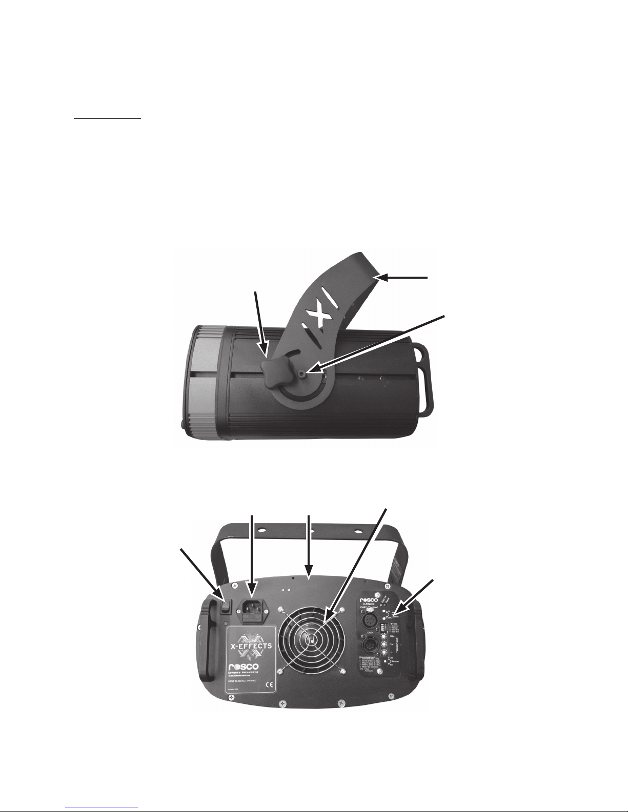
SIDE VIEW
Yoke Tilt Knob
Yoke
Cap Screw
BACK VIEW
Power Switch
6
Line
Connection
Top Lid
Fan
Control Panel -
Analog or DMX
X24 PROJECTOR ORIGINAL INSTRUCTIONS
Page 7

TOP VIEW
Lamp Mount
Lamp Clip
Lamp
www.rosco.com
Special Optics Slot
7
Page 8
Wheel Module
The wheel module is made up of motors for rotating two overlapping glass patterns.
It also has four shutters and a slot for placing an E-size gobo.
Note: In older versions of the X24 the glass discs were made to a thinner specification.
These should not be used in the latest version of the unit as this may result in damage to the
drive pulley.
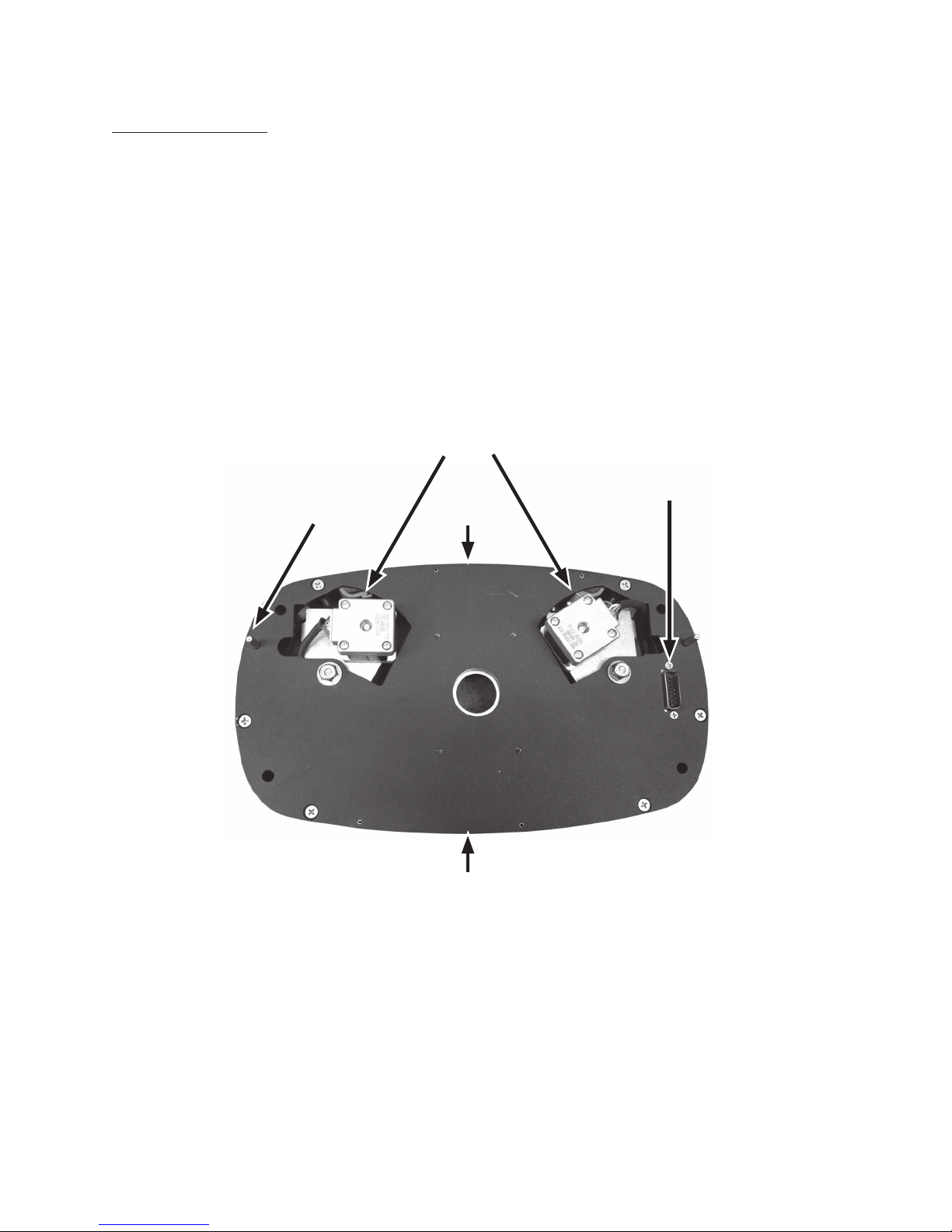
BACK VIEW
Motor
Alignment
Pin
Connector
Top Lid
Bottom Lid
8
X24 PROJECTOR ORIGINAL INSTRUCTIONS
Page 9
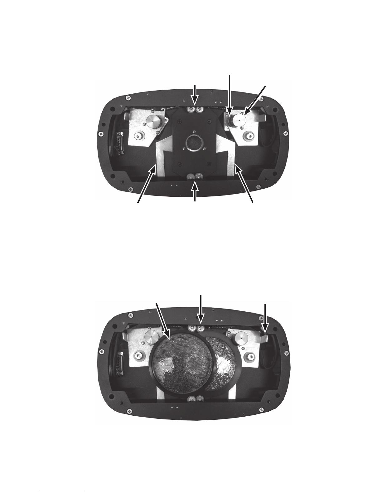
FRONT VIEW
Side Shutter
Top Shutter
(Not in View)
Bottom Shutter
(Not in View)
Drive Pulley
Damper
Side Shutter
FRONT VIEW (with wheels fitted)
Glass Pattern
(Standard Water)
Idler Wheel
Pull Tab
www.rosco.com
9
Page 10

Lens Module
The lens module provides the mounting for the various lens barrels.
At the present time there are barrels available in 19°, 30°, 50° and 70° beam angles.
It provides screw focusing and a lock-down knob.
The lens barrels themselves also have a slot for inserting a dichroic filter. (See page 14).
FRONT VIEW
10
# 20 Screw
Thumb Screw
Locking Knob
Lens Mount
Ring
X24 PROJECTOR ORIGINAL INSTRUCTIONS
Page 11

Analog Control Panel
The analog control panel has all of the panel controls and electronics for controlling the
electronic dimming of the lamp.
(For DMX see page 17)
Control Power Indicator
Speed
Adjustment
Speed Mode
Switch
Brightness
Adjuster
www.rosco.com
11
Page 12

PREPARING FOR USE
Installing the Lamp (Base Unit)
1. Unplug the unit.
2. Open the hinged lid on the top of the base unit.
3. Pull the lamp clip back away from the lamp gasket. Insert the lamp so that the front of the
reflector is seated in the lamp gasket. The wire exiting from the front of the reflector should
be positioned in the cut-out of the gasket.
4. Release the lamp spring clip to lock the rear of the lamp in place.
5. Attach the connector from the lamp to the connector in the unit. It is a polarized connector
and will only connect in one position.
12
Cutout
Wire
Lamp Clip
X24 PROJECTOR ORIGINAL INSTRUCTIONS
Page 13

Installing a Glass Pattern (Wheel Module)
1. Unplug the unit.
2. Remove the lens module pmb knobs on the front.
3. Look for the pull tabs on the plates with metal pulleys on either side.
4. These pull the plates outward for installing new glass patterns.
5. Once the plate is pulled outward, the pattern should be inserted such that the metal ring
sits in the groove in the rubber drive pulley and in the 2 plastic idle wheels on the
corresponding side.
Notes: Only use 0.1in/2.5mm discs. Thinner discs risk damage to drive pulley.
Observe correct orientation of the two discs.
Once the discs are in position, the pull tab can be released.
6. Replace the lens module plate on the unit by lining up the mounting pins, then tightening
the three thumb screws.
7. Tighten the thumb screw by hand to hold the lens barrel in position.
Drive Pulley with
Pull Tab
Damper Fitted
Metal Ring
Idler Wheel
www.rosco.com
13
Page 14

Installing a Lens Barrel (Lens Accessory)
1. Unplug the unit.
2. Remove the lens mount plate from the unit by loosening the three knobs on the
front.
3. Loosen the thumb screw on the lens barrel holding ring.
4. Remove the dichroic glass ring from the rear of the lens barrel.
5. Thread the lens barrel into the holding ring (CW screws it in).
6. Optional] Place a dichroic filter in the rear of the lens barrel.
7. Replace the dichroic glass ring on the rear of the lens barrel.
8. Replace the lens mount plate on the unit by lining up the mounting pins, then tightening
the three knobs.
9. Tighten the thumb screw by hand to hold the lens barrel in position.
Thumb Screw
LENS BARREL
14
Lens Barrel
Locking Knob
Dichroic Glass
Filter
X24 PROJECTOR ORIGINAL INSTRUCTIONS
Dichroic
Glass Ring
Page 15

UNIT OPERATION (ANALOG, WHEEL, LENS)
Mounting
The yoke angle can be adjusted by loosening the tilt knob on both sides of the unit.
In order to slide the yoke back and forth in its track, it is also necessary to loosen the cap screw
at the pivot point.
When loosening the cap screw, it is strongly recommended to do this prior to hanging the unit
to minimize the risk of the unit falling.
The unit can be hung from any C-clamp or other mounting device that uses a suitable bolt. The
three holes in the yoke are provided for this purpose.
The use of a safety cable is strongly recommended when hung overhead. Also make sure not to
block the top, bottom, or rear vents when mounted.
Powering Up
• Check to make sure that a lamp is installed.
• Make sure the power switch is in the off position and the hinged lid on the base unit is
fully closed.
• Ensure the area in front of the lens is free of combustible materials.
• Plug the unit in (check electrical specifications to ensure compatibility).
• Flip the power switch to the on position.
a) If there are no lights on the rear of the unit, check the power cord and the circuit that
the unit is connected to. Check also the fuse in the unit.
b) If the control panel lights, but there is no sound or lamp light indication, check that
the lid is fully closed.
Note: there is a safety sensor on the lid. If the lid is open the lamp will not light.
c) If the control panel lights, and there is a ticking sound accompanied by flashing of the
lamp indicator, wait 30 seconds, then turn the unit off. Wait a couple minutes, then try
again. If it still does not work, the lamp may need to be replaced.
d) If the control panel lights and the lamp indicator comes on, then the unit is operating
properly, but it will take a couple of minutes for the lamp to warm up.
• Once the lamp is warmed up the unit can be adjusted to suit your needs.
www.rosco.com
15
Page 16

Adjusting Brightness
• Using a small flat screwdriver, turn the adjustment on the control panel to achieve the
desired brightness.
Note: Maximum electronic dimming range is 160-200W.
Adjusting Focus
• Loosen the thumb screw on the lens barrel holding ring.
• Rotate the lens barrel to adjust the focus.
• Tighten the thumb screw by hand to hold the lens barrel in position.
Important: It is possible for the lens barrel to come in contact with a pattern while
focusing. Do not force the lens barrel if it stops moving or encounters resistance.
Proper rotation of patterns may require the lens to be backed off a bit.
Adjusting Wheel Speed and Direction
• The switches on the control panel will select between 3 speed modes: “Off”, “Slow”, and
“Fast”. One switch for each wheel.
• Turn the control panel knobs to fine tune the speed. One knob for each wheel.
• The potentiometer knobs can be pulled out or pushed in to change the direction of the
wheels.
Adjusting Shutters on the Wheel Module
• Open the top and bottom hinged lids on the wheel accessory.
• The top lid gives access to the top shutter.
• The bottom lid gives access to the bottom and side shutters.
• Close the top and bottom lids.
16
X24 PROJECTOR ORIGINAL INSTRUCTIONS
Page 17

DMX CONTROL MODULE
The DMX Control Module allows basic manual and full DMX control of the X-24 projector and
its accessories. While some of the panel controls (Power, Dimmer, and DMX OK) are common to
both manual and DMX modes, most are used only in a single mode.
www.rosco.com
17
Page 18

Dowser
The dowser is fitted behind the front motor module and is only fitted to the DMX version of the
X24.
It allows for reduction of the light output, fades and blackout by use of one DMX channel.
(See page 21).
When the unit is powered up the dowser will reset itself.
Dowser Shown in Open Position
18
X24 PROJECTOR ORIGINAL INSTRUCTIONS
Page 19

Manual Mode
By turning DIP switch #3 ON, the module is placed into manual mode.
This will automatically turn the lamp on and open the dowser (if present). This mode also allows
manual control of the dual wheel accessory.
The speed of the two wheels can be adjusted by turning the two shafts near the top of the
module (full CW is fastest speed, full CCW is stop).
The direction of the two wheels can be adjusted by changing the position of DIP switches #1
and #2. Additionally, the brightness of the lamp can be adjusted by the shaft near the bottom
of the module with a small flat screwdriver (full CCW is 200W, full CW is 160W).
Note: the DMX OK indicator will light if DMX is connected to the unit, even if the unit is not in
DMX Mode.
www.rosco.com
19
Page 20

DMX Mode
By turning DIP switch #3 OFF, the module is placed into DMX mode.
The unit can then be part of a standard DMX control system.
Standard male and female 5-pin XLR connectors are provided for easy connection. (Pin 1 =
Ground, pin 2 = Data-, pin 3 = Data+. Pins 4 & 5 are not used by this unit).
Furthermore, the unit has pass-through wiring for easy daisy-chaining of multiple units. The
DMX OK indicator will light if the unit is powered up and receiving a valid DMX stream.
We recommend the use of a 120 ohm termination at the end of the DMX cable run for highest
reliability and best performance.
The starting address of the unit can be set by the three rotary switches in the middle of the
module.
20
X24 PROJECTOR ORIGINAL INSTRUCTIONS
Page 21

Each switch gives one digit in of the starting address, 1s, 10s, or 100s. If an invalid address is
entered (0 or 513-999), the unit defaults to using a starting address of 1.
The unit uses 5-13 DMX channels depending on the accessories used. In the standard
configuration with Dowser and Dual-Wheel Accessory, it uses only 5 channels.
Additional channels are built into the system for future accessories. The table below describes
all functionality.
Note that the lamp brightness function is not controlled by DMX. It is controlled in the same
way as in Manual Mode.
When the unit powers up in DMX mode, the lamp will be off and the shutter will be in the closed
position.
If no DMX signal is detected, the system will stay in that state.
If a valid DMX signal is detected and the unit has finished homing, it will be fully controllable as
described above.
www.rosco.com
21
Page 22

TROUBLESHOOTING
1. Power indicator will not light.
• Check that unit is plugged in and turned on.
• Check that the fuse has not blown.
2. Power indicator lights, but DMX OK indicator will not light.
• Check that unit is properly connected to a DMX controller.
• Check cabling.
• Check DMX signal with another device.
• Check that DMX cable run is properly terminated.
3. DMX OK indicator flashes erratically and/or unit behaves erratically.
• Check that DMX cable run is properly terminated.
4. DMX OK indicator lights, but unit does not respond to commands.
• Check that the DIP switch #3 is in the OFF position.
• Check channel addressing.
5. Unit seems to respond to DMX, but not with all functionality.
• Check the mechanics of the missing functionality to ensure that all parts can move
freely and belts are properly in place.
• If all else fails, the module can be slid partially out of the unit so that the connections
can be checked.
• The diagram below shows the location of key connections.
6. Fan does not operate.
• Check the lamp has not failed. The fan will not run without the lamp.
22
X24 PROJECTOR ORIGINAL INSTRUCTIONS
Page 23

For the most part, connectors can be matched up to headers on the PCB. The only exception is
the relay and power headers, which are identical. The relay cable uses two blue wires while the
power cable uses a red/black combination.
www.rosco.com
23
Page 24

SPECIFICATIONS
Mechanical Specifications
Base Unit Size w/o Yoke: 14”L x 7”H x 12”W
35.5cm x 18cm x 30.5cm
Yoke Mounting Distance: 6.57”/167mm to mounting plane from pivot
Wheel Module Length: 1.5”/38mm
Lens Module Length: 1.27”/32.4mm (does not include barrel)
Complete Unit Weight: 18.1 lbs./8.21 kg
Electrical Specifications
Line Connection: 100-240 VAC 50/60hz
250W
IEC 320 Grounded Outlet with Fuse
Fuse – 5x20mm, 5A, 250V, Slo-Blo
Power Factor Correction on Lamp Ballast
Accessory Power Supply: 24VDC @ 60W Max
Self-Protection: Internal Thermal Protection on All Internal Electronics
Short-Circuit Protection on Accessory Power Supply Internal Fan
Environmental: 50C Maximum Ambient
Wheel Module Specifications
Wheel Speeds: At High Speed: .631-9 RPM
At Low Speed: .375 - .8 RPM
Wheel Module Gobo: X-size patterns: Metal or glass in bezel
Aperture: 1.04”/26.4mm between Shutter Sets
Lamp Specifications
Use only an USHIO 200W EmArc Lamp with Ellipsoidal Reflector (SMR200 D1).
Failure to do so may damage the unit and void the warranty.
Maximum electronic dimming is to 160W.
Lens Module Specification
70º Lens Barrel - Focal Length: 18mm
50º Lens Barrel - Focal Length: 27mm
30º Lens Barrel - Focal Length: 46.7mm
19º Lens Barrel - Focal Length: 80mm
24
X24 PROJECTOR ORIGINAL INSTRUCTIONS
Page 25

LIMITED LIABILITY WARRANTY
Rosco products are covered by a limited liability warranty from defects in material and workmanship. This warranty does not apply if, in the judgement of Rosco, the product fails due to
damage from shipment, handling, storage, accident, abuse or misuse, or if it has been used or
maintained in a manner not conforming to product’s instructions, has been modified in any
way, or has a defaced or removed serial number.
Repair by anyone other than Rosco or a qualified Dealer voids this warranty. In accordance with
the terms and conditions of this warranty, Rosco’s liability is limited to the product itself, up to
the full purchase price of the good’s.
ONE-YEAR PARTS AND LABOR SERVICE WARRANTY
The Rosco X-Effects Projector is covered by a one- year parts and labor warranty. This warranty
covers replacement and repair at the discretion of Rosco on all parts excluding the lamp (Ushio
EmArc) and the supplied X-size effects discs.
In the event that the product needs repair or return, an RMA (Return Merchandise Authorization)
is required.
Please contact Rosco Customer Service at 1-800-767-2669.
Any repair units received after their 1 year warranty has expired will be repaired and billed to
the customer in full including shipping charges
www.rosco.com
25
Page 26

EC Declaration of Conformity
In accordance with EN ISO 17050-1:2004
Dated: November 2012
We: Rosco Laboratories Inc.
Of: 52 Harbor View Ave
Stamford CT 06902
In accordance with the following Directive(s):-
2004/108/EEC The Electromagnetic Compatibility Directive
Hereby declare that:
Professional Lighting Control Products/X24 Projector
Is in conformity with the applicable requirements of the following documents:-
Ref. No. Title Edition/date
BS EN 61000-6-3 Conducted Emissions 2007
Radiated Emissions
BS EN 61000-3-2 Harmonic Emissions 2006
BS EN 61000-6-1 Immunity to Radiated Electromagnetic Fields 2007
Immunity to Fast Transient Bursts - AC Power Lines
Immunity to Fast Transient Bursts - Signal Lines
Immunity to Conducted Field - AC Power Lines
Immunity to Conducted Field - Signal Lines
Immunity to Voltage Dips- AC Power Lines
Immunity to Voltage Surges - AC Power Lines
Immunity to Electrostatic Discharge
I hereby declare that the equipment named above has been designed to comply with
the relevant sections of the above referenced specifications. The unit complies with
all applicable Essential Requirements of the Directives.
Signed by: 01/02/2013
Joshua Alemany Date
Director of Product Marketing
26
X24 PROJECTOR ORIGINAL INSTRUCTIONS
Page 27

www.rosco.com
 Loading...