

Page 1

1
FORKLIFT CAMERA SYSTEM
INSTALLATIO N & O PERATING INSTRUCTIONS
KIT# STSK7316
ROSCO INC.
90-21 144TH PLACE,
JAMAICA, NEW YORK 11435
WWW.ROSCOVISION.COM
Version 1.0
©2013 Rosco® Vision Systems, All Rights Reserved
Specifications and details are subject to change without prior notice.
Page 2

2
TABLE OF CONTENTS
FEATURES ................................................................................................................ 3
KIT CONTENTS ......................................................................................................... 3
INSTALLATION ......................................................................................................... 4
MONITOR ....................................................................................................................... 4
MONITOR INSTALLATION DIAGRAM .............................................................................. 5
WIRING DIAGRAM ......................................................................................................... 6
WIRING .......................................................................................................................... 7
CAMERA ......................................................................................................................... 8
CAMERA INSTALLATION DIAGRAM ................................................................................ 9
MONITOR FUNCTIONS ................................................................................................. 10
MONITOR SET UP ......................................................................................................... 12
TROUBLESHOOTING ............................................................................................. 13
TECHNICAL SPECIFIC ATIONS .............................................................................. 14
STSM207 MONITOR SPECIFICATIONS .......................................................................... 14
STSC107 CAMERA SPECIFICATIONS .............................................................................. 15
SPARE PARTS LIST ............................................................................................... 16
OPTIONAL PARTS LIST ......................................................................................... 16
COMMERCIAL WARRANTY ................................................................................... 17
Page 3
3
FEATURES
MONITOR
• Heavy Duty Aluminum Housing
• 7 Inch Wide WVGA Bright Display
• Waterproof (Indoor & Outdoor)
• Up to 4 Camera Inputs
• Split Screen Function
CAMERA
• Rugged Shock Resistant Metal Housing
• Stainless Steel Bracket
• Waterproof
• Heated
• Built-in IR For Night Vision
• Audio
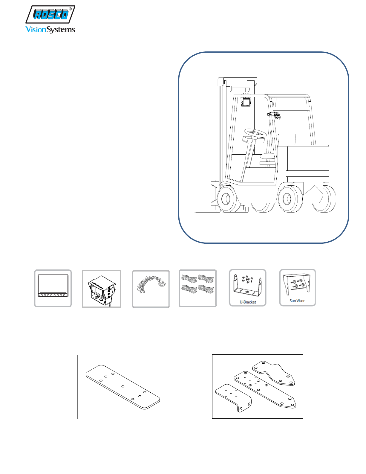
KIT CONTENTS
Before use this products, please check below contents.
MONITOR CAMERA CABLES 4 SETS OF U-BRACKET SUNSHADE (optional)
Trigger Wires
Your kit will contain the following hardware:
Monitor U-Bracket Backing Plate plus hardware Camera Mounting Plates plus hardware
Page 4
4
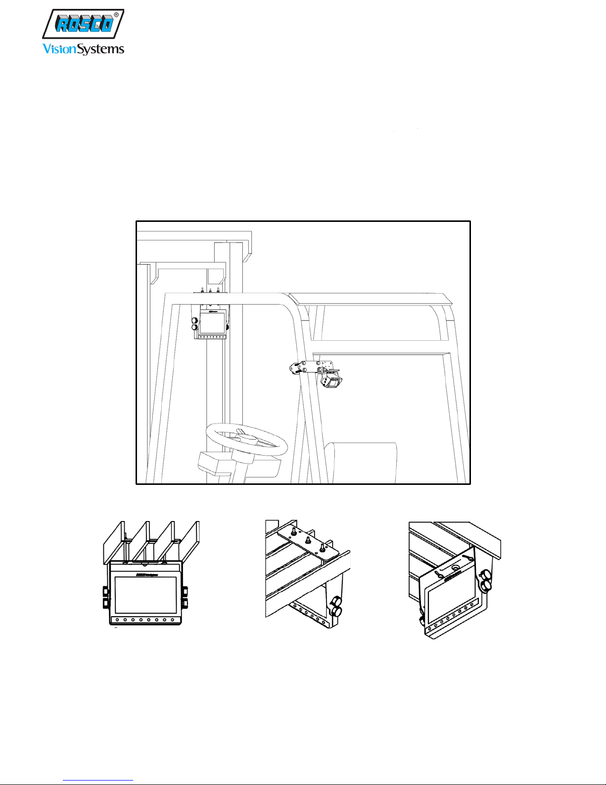
INSTALLATION
MONITOR
Locate a suitable position for monitor, using caution to make sure that the operator’s forward field of
vision is not obstructed. Recommended mounting is overhead, utilizing the included U-Bracket with
backing plate and hardware, as shown in these examples:
Page 5
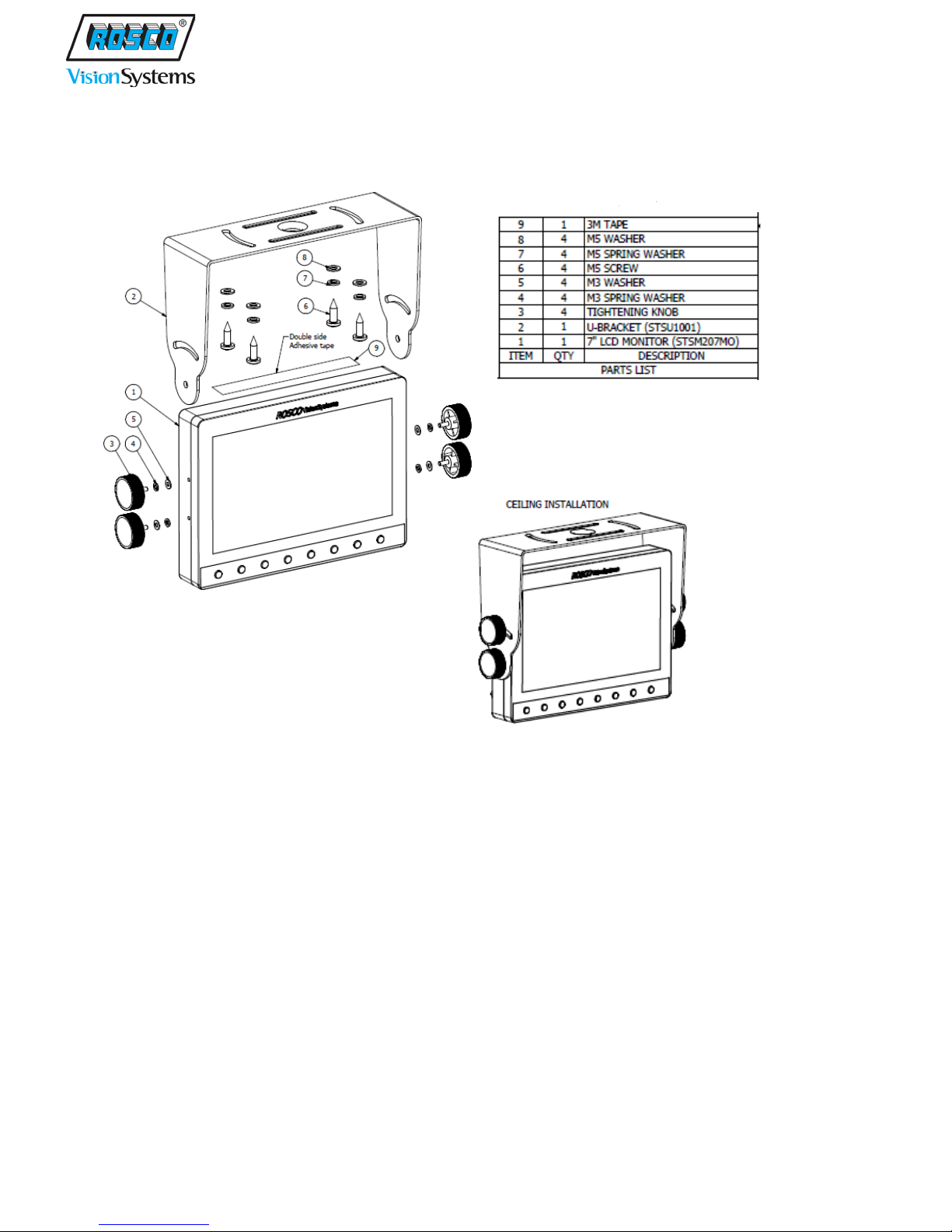
5
MONITOR INSTALLATION DIAGRAM
Page 6
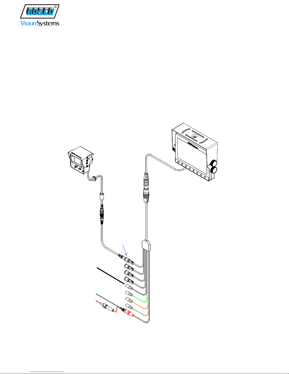
6
STSC107 Camera
STSH308
STSM207 Monitor
STSH347
STSH338
BLACK
CAMERA 1
Input
WIRING DIAGRAM
After installing the Monitor, connect it to Video Input/Power Harness as shown. The connect Power
Cable to the battery or Voltage Converter (see next section). Secure the wires and activate the Monitor.
Connect the Camera 1 trigger wire as desired ( for example, to reverse gear or backup lights/alarm
circuit). This will allow the operator to choose between having the Monitor on at all times or only active
during reverse travel.
Connect the Camera Extension Cable to the Camera 1 Input on the Video Input/Power Harness, and then
connect the Camera’s cable to the Camera Extension Cable. This will allow the installer to determine the
best possible Camera location.
16’ Camera
Extension
(CAMERA 1)
Trigger Input
Power Cable
Video Input/Power
Camera
Page 7

7
OR
+ 12VDC INPUT
CAMERA SYSTEM
WIRING
Connect STSK7316 Power Wire (RED) to 12-24VDC source as provided on the vehicle. Note that
FORKLIFT may be equipped with a Voltage Converter as shown here:
POWER TO
Page 8

8
CAMERA
With the Camera powered but not permanently installed, move it around to locate a suitable position,
either within the Forklift frame or in an area not susceptible to damage, which will provide a clear view
of the desired area. Recommended mounting is high on the frame. Using the universal camera mounting
brackets and hardware, install the camera and fasten securely as shown in these examples:
Secure all cables with tie-wraps or as otherwise necessary. The system is now ready to operate as a
single-camera operation. For multiple views, additional cameras may be installed and individually
connected to the appropriate inputs on the Video Input/Power Harness.
Page 9

9
CAMERA INSTALLATION DIAGRAM
Page 10

10
NAME
DESCRIPTION
A
LCD Screen
7” Wide VGA (800x480) LCD Display
B
Automatic Dimmer Sensor
Sensor to control LCD brightness (Day/Night)
C
Dimmer Button
Press to set up dimmer function: Day/Night/Auto
D
MODE Button
Press to select and change split screens: Full, 2, 3, 4
E
Move Button (down)
Press to move down menu options
F
Move Button (up)
Press to move up menu options
G
Select Button (left)
Press to select or adjust values of selected menu option
H
Select Button (right)
Press to select or adjust values of selected menu option
I
MENU Button
Press to open on-screen menu options
J
Power Button
Press to turn ON/OFF power
K
Stand-by LED
White LED on in stand-by mode
A
B
C D E
F G H
I
J
K
MONITOR FUNCTION BUTTONS
MONITOR FUNCTIONS
Page 11

11
1. POWER
When the ignition is switched on, the monitor will be in standby mode, and the Standby LED will be lit.
The trigger wire will be energized when the vehicle shifts into reverse gear, and the image captured by
the selected camera will appear on the monitor.
2. Pressing the Power button will change the monitor status from standby to steady-on, even when no
trigger wire is energized. Steady-on mode status will show camera view depending on user selection.
3. Adjust Volume
Power on Monitor, press button and adjust Speaker Volume. (0~100)
These buttons are also used to adjust the values within selected setting of menu option. Factory default
volume is set to 30. The volume control works only in CAM1 Screen.
4. MENU Button:
Press the Power button, then press MENU button to open on-screen options.
Press MENU to cycle through choices and use button to change your settings.
5. MODE Button:
Press MODE button to switch Full Screen => 2 Split Screen => 3 Split Screen => 4 Split Screen => Full
Screen. In the split screen mode, press button to change the different split screens.
6. Camera View Selection
In the Full Screen mode, press button to change Camera View.
**NOTE: The reverse camera (CAMERA1) has selectable back up grid when triggered.
Page 12

12
MONITOR SET UP
Press to increase/decrease the Volume level (0 – 100)
Press the MENU button once and set MARKER SETUP option ON or OFF.
Press to accept.
Press the MENU button twice to set desired Camera Views (MIRROR or NORMAL)
Press button to select Camera (CAM 1, CAM 2, CAM 3, and CAM 4)
Press to change option and wait 10 seconds to exit
Press the MENU button three times to set up PICTURE.
Press button to select the menu options (Dimmer, Contrast, Brightness, Color, Tint,
Language, Video System and RESET)
Press to change or increase/decrease values.
Wait 10 seconds to exit setup mode.
Press the MENU button four times to set MARKER SELECT.
Press to select desired marker position. (P1 ~ P7)
Wait 10 seconds to exit setup mode.
Press the MENU button five times to set MARKER ADJUST.
Press to select Horizontal or Vertical Marker
Press to adjust marker values and set up position
Press MENU button once or wait 10 seconds to exit setup mode.
IMPORTANT:
At first power up after installation, the monitor may display split screen. Once the operator selects
single camera view (either manually or by reverse trigger), this setting will be memorized and will
appear upon subsequent system starts.
On-screen menu commands may only be selected when monitor is in Steady-on mode.
For your safety, never change settings while operating vehicle.
Page 13

13
No Power
Power Cable
Check the voltage & fuse in the power cable
No Imag e
Camera
Check the voltage in the camera cable, secure connector
Monitor
Check the reverse trigger wire connection, re-secure
camera input connector.
Extension Cable
Check for cable damage and secure the connector.
Image is not clear
Camera Lens
Check and clean dirt or moisture on the glass with a
blocked. Check if the camera lens is damaged
Monitor Color
If the screen image is fuzzy, adjust color, brightness and
properly.
Blue/Black Screen
Camera
Check the camera cable connection and secure it
Monitor
Power on/off Monitor and see if it clears the problem
Check and see if MENU button is working normal
Can’t adjust on-
Menu disabled
For safety reasons, on-screen menus lock out while in
mode.
Split screens appear
Monitor
Press MODE button few times and change split screens to
upon subsequent system starts.
No video signal
reversing the vehicle
Camera
Check and secure the reverse trigger wire connection and
TROUBLESHOOTING
SYMPTOM CAUSE REMEDY
slightly damp soft cloth.
Check and fix if the camera is not in the proper position or
screen menus
while reversing the
vehicle
appears while
contrast controls using the MENU options in the monitor.
Check and fix if Day/Night/Auto Dimmer option is not set
trigger mode. Only adjust on-screen menus in steady-on
show Channel 1 full mode screen only. Once operator
selects single camera view (either manually or by reverse
trigger), this setting will be memorized and will appear
also secure the camera video input connection.
Page 14

14
TECHNICAL SPECIFICATIONS
STSM207 MONITOR SPECIFICATIONS
ROSCO PART NUMBER: STSM207
PRODUCT NAME: 7” COLOR WATERPROOF MONITOR
FEATURE DESCRIPTION
ROSCO’s STSM207 7”Color Waterproof Monitor display live vid eos as selected by Forklift operator.
The monitor has 7 inch WVGA (800x480) Wide LCD Panel which accepts 4-Camera Input view with 2,
3, 4 Split Screen Function.
ELECTRICAL SPECIFICATIONS
• Input Voltage: 12VDC ~ 24VDC
• Power Consumption: 450mA Max.
TECHNICAL SPECIFICATIONS
• Screen: 7 inch Color TFT LCD
• Resolution: WVGA (800x480), Contrast Ratio 300:1
• Brightness: 400cd/m²
• Input System: NTSC/PAL
• Frequency: NTSC (H: 15.734KHz / V: 59.94Hz), PAL (H: 15.625 KHz / V: 50Hz)
• Effective Pixels: NTSC 250,000 Pixel, PAL 290,000 Pixel
• Viewing Angles (L/R/U/D): 70° / 70° / 50° / 70°
• Speaker: 8 Ohms, 0.5W Max.
• Audio Input Signal: Mono,
• Video Input Signal: Composite Video (CVBS)
• Language Display Selection: ENGLISH-FRANCH-GERMAN-ITALIAN-SPANISH
• Operating Temperature: -30°C to +70°C (-22°F to +158°F)
• Storage Temperature: -40°C to +80°C (-40°F to +176°F)
• Housing: Aluminum die-casting
• Dimmer Sensor: built-in, Sun Shade: Included
• Weight: 780g (monitor only)
• Dimension: 181 (W) x 134 (H) x 28 (D) mm
• Waterproof: IP-67
Page 15

15
STSC107 CAMERA SPECIFICATIONS
ROSCO PART NUMBER: STSC107
PRODUCT NAME: COLOR CAMERA
FEATURE DESCRIPTION
STSC107 Color Camera provides views of areas behind the Forklift operator. The camera provides up to
a 30-foot range view and a 145° diagonal field of vision. Mount the camera universally to the back side
of the vehicle, and adjust the camera mount to view and use it as a backup camera.
ELECTRICAL SPECIFICATIONS
• Input Voltage: 12 VDC
• Power Consumption: 200mA Max.
TECHNICAL SPECIFICATIONS
• Image Sensor: 1/3” COLOR CCD Image Sensor
• TV System: NTSC
• Effective Pixels: NTSC 250,000 Pixel, PAL 290,000 Pixel
• Viewing Angles: 145° (D) / 114° (H) / 85° (V)
• Audio Function: Yes
• LED Light: 6 IR LEDs for Night Vision
• Auto Light Sensor: Yes
• Minimum Illumination: 0.1 lux
• White Balance & Gain control: Auto
• Sync System: Internal Sync.
• Video Output: 1.0Vp~p, 75Ω
• Operating Temperature: -30°C to +70°C (-22°F to +158°F)
• Storage Temperature: -40°C to +80°C (-40°F to +176°F)
• Heating function built-in
• Aluminum die-casting housing
• Waterproof: IP-67
• Dimension: 70 (W) x 44 (H) x 57 (D) mm
• Weight: 400g (with bracket)
Page 16

16
ROSCO P/N
DESCRIPTION
STSK7316
COMPLETE FORKLIFT CAMERA SYSTEM KIT
STSM207
COMPLETE MONITOR KIT, CONTAINS ALL OF THE MONITOR PARTS BELOW
STSM207MO
MONITOR,7"WATERPROOF LCD MON OPT, 4 CAM
STSU1001
U BRACKET, MONITOR MOUNT WITH THUMB SCREWS (4)
STSH338
BARREL CONNECTOR, FUSE & POWER FOR STSM207 MONITOR
STSH344
TRIGGER EXTENSION CABLES (4pcs)
STSH347
HARNESS,COLOR MONITR INPUT/POWER,4 CAM
STSC107
COMPLETE CAMERA KIT, CONTAINS ALL OF THE CAMERA PARTS BELOW
STSC107CO
CAMERA, COLOR, HEATED, NITE VISION, AUDIO,145º (D) FOV
STSC107MT
MOUNTING KIT FOR STSC107
STSH308
HARNESS, 16.5', 6 PIN M MINIDIN PUSH,6 PIN FML TWST
SCR7153
SCREW KIT, MOUNTING HARDWARE, LIFTTRUCK MONITOR, STSM207MO
SCR7149
SCREW KIT, MOUNTING HARDWARE, LIFTTRUCK CAMERA, STSC107CO
ROSCO P/N
DESCRIPTION
STSH307
HARNESS, 60’, 6 PIN M MINIDIN PUSH, 6 PIN FML TWST
STSH309
HARNESS, 16.5’, EXTENSION ONLY, M/F 6 PIN TWIST
STSC117
COMPLETE TILT CAMERA KIT, CONTAINS ALL OF THE CAMERA PARTS BELOW
STSC117CO
CAMERA, COLOR, HEATED, TILT, NITE VISION, AUDIO,120º (D) FOV
STSC117MT
MOUNTING KIT AND MANUAL FOR STSC117
STSC127
COMPLETE SHUTTER CAMERA KIT, CONTAINS ALL OF THE CAMERA PARTS BELOW
STSC127CO
CAMERA, COLOR, HEATED, SHUTTER, NITE VISION, AUDIO,120º (D) FOV
STSC127MT
MOUNTING KIT AND MANUAL FOR STSC127
STSC128
COMPLETE UNIVERSAL SIDE-VIEW CAMERA KIT
STSC128CO
CAMERA, COLOR, UNIVERSAL SIDE CAM, 30FT RANGE, 110º (D) FOV
STSC128MT
MOUNTING KIT AND MANUAL FOR STSC128
SPARE PARTS LIST
OPTIONAL PARTS LIST
Page 17

17
COMMERCIAL WARRANTY
We warrant that all ROSCO mirror, camera, sun visor, and electronic vision products are
free from defects in workmanship and materials for a period of ONE (1) YEAR from the
date of receipt of the product. During the warranty period, we agree to provide a replacement
for (or at our option, repair) the ROSCO product and/or any one or more component parts of
a ROSCO product which malfunctions under normal use and serv i ce.
Upon discovering a defect, the customer must contact ROSCO for a return
authorization and then must return the product, and/or component part, together with proof
of date of receipt of the product, to ROSCO INC. 144-31 91st Ave. Jamaica, New York
11435. The customer and not ROSCO will be responsible for the payment of all removal,
installation and transportation charges for return of defective products or components to
ROSCO. Transportation charges for such return must be prepaid. The repaired or replaced
equipment will be returned to the customer with transportation charges prepaid by ROSCO.
Replacement (or repaired) products and/or component parts are warranted only for the
unexpired term of the original warranty.
This warranty does not cover defects caused by neglect, misuse, incorrect application,
incorrect installation, water damage, vehicle wash facilities, alteration or repair in any manner
outside ROSCO’s factory. Damage caused by the return shipment due to inadequate
packaging or mishandling will not be covered. If the alleged defect is due to any of these
causes, the customer will be advised of the findings and asked what action is to be taken. If
ROSCO is requested to repair the product, a repair charge estimate will be prepared and
the customer’s written permission (purchase order, repair, etc.) will be necessary to proceed
with the repair of the product and/or component part. Transportation charges for such
returns will be the responsibility of the customer.
This warranty may not be expanded by oral representation, written sales information, and
drawings or otherwise. Repair or replacement is the exclusive remedy for defective
products under this warranty. This warranty is expressly in lieu of all other warranties,
including any implied warranty of merchantability or any implied warranty of fitness for a
particular purpose on any ROSCO product. ROSCO shall not be liable for any
consequential or incidental damages for breach of any express or implied warranty on any
ROSCO product.
 Loading...