

Page 1
REARVIEW MIRROR/MONITOR COMBO
BACKUP CAMERA SYSTEM
INSTALLATION/USER’S MANUAL
STSK4532 with Bumper Bullet Camera (P/N:STSC106)
STSK4533 with License Plate Camera (P/N:STSC112)
Page 2
STSK4532, STSK4533 Installation/Users Manual
2
3
CONTENTS
Rearview Mirror/Monitor Combo Backup Camera System ................................. 2
Component List ........................................................................................................3-4
How To Operate Display / Monitor Specifications ............................................... 5
.
Wiring Diagram ........................................................................................................ 6-7
Camera Specifications ............................................................................................. 8
Rearview Mirror Installation ..................................................................................... 9
Camera Installation .................................................................................................. 10
Testing ....................................................................................................................... 11
Rosco Vision Systems introduces a revolutionary new backup camera system
for small to medium vehicles. MOR-Vision
TM
utilizes an interior rearview mirror
to display a 4.3” LCD monitor when the vehicle shifts into reverse. This monitor
allows the driver to see behind the vehicle for added convenience and safety.
The camera has an advanced CMOS lens sensor able to process excellent
images under dark and light conditions. The camera has a 170° diagonal field of
vision giving superb coverage behind the vehicle and complies with the latest
NHTSA 49 CFR Parts 571 and 585 (RIN 2127-AK43).
MOR-VISION™ REARVIEW MIRROR/MONITOR COMBO BACKUP CAMERA SYSTEM
General Technical Specifications:
Power Supply: 12VDC
Power Consumption: 1 Watt
Current Draw: <2000 mA
Video Input: composite video; 1 Vp-p@75 impedance
Operating Temp: -5°F to 150°F(-20°C to 65°C)
Monitor Dimensions: 11” W x 3” H x 1.5” D
1. Wire Tester 4. Wire Stripper
2. Phillips Screwdriver 5. Pencil
3. Tape Measure 6. 31 mm /1.25” hole saw /step drill bit, 5/16 drill bit
7. Drill
8. Tape
STSM230
STSM230MO
STSH343
Notes:
• Please read this manual carefully before using the product.
• This system is intended as an aid to safe reverse operation.
Drivers must always use extreme caution when operating a vehicle.
• Specifications subject to change without prior notice.
Warning:
• To prevent electrical shock, DO NOT OPEN MONITOR CASE.
• Avoid exposing monitor to water, rain, moisture etc.
• Do not disassemble the camera. This voids the warranty. Disassembling the
camera will compromise the waterproof seal.
STSDF1003
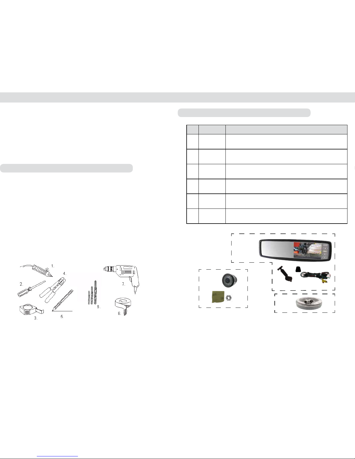
STSC106
QTY
P/N
DESCRIPTION
1
STSC106 Wide angle color bullet camera
2
STSM230
Back up camera mirror/monitor includes:
P/N STSM231MO 4.3” clip on color mirror/monitor
P/N STSK4530/PHAR monitor power harness
3
STSH343 Backup camera extension harness, 33FT
4 STSH373 4 - Pin to RCA adapter
5 CON1048 Male - Male RCA adapter
6 STSH374 Power adapter for STSH373
STSK4530/PHAR
COMPONENT LIST - STSK4532
Page 3
STSK4532, STSK4533 Installation/Users Manual
4
5
COMPONENT LIST - STSK4533
Notes:
• Please read this manual carefully before using the product.
• This system is intended as an aid to safe reverse operation.
Drivers must always use extreme caution when operating a vehicle.
• Specifications subject to change without prior notice.
Warning:
• To prevent electrical shock, DO NOT OPEN MONITOR CASE.
• Avoid exposing monitor to water, rain, moisture etc.
• Do not disassemble the camera. This voids the warranty. Disassembling the camera will
compromise the waterproof seal.
STSM230
STSM230MO
STSK4530/PHAR
STSH343
STSDF1003
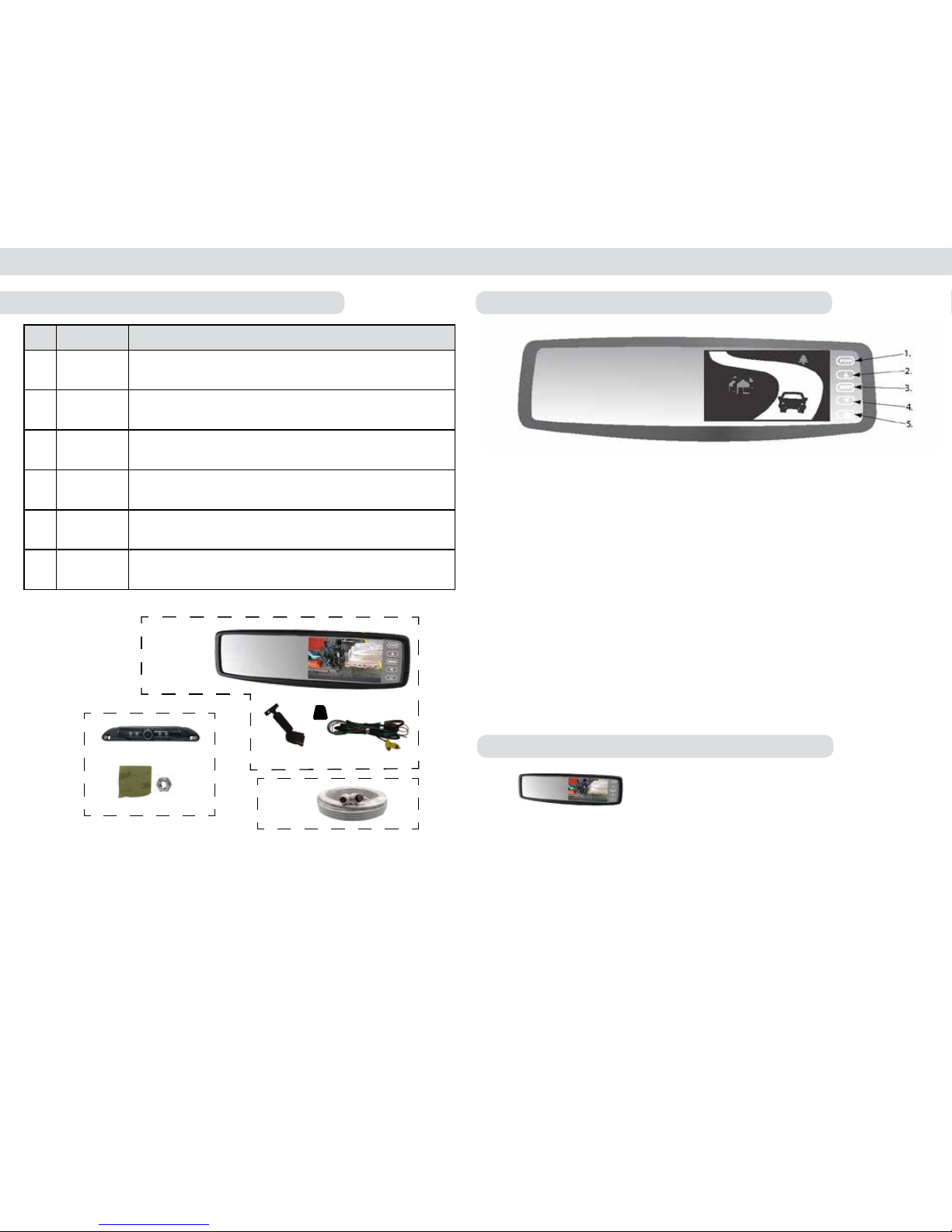
STSC112
QTY
P/N
DESCRIPTION
1
STSC112 License plate camera
2
STSM230
Back up camera mirror/monitor includes:
P/N STSM231MO 4.3” clip on color mirror/monitor
P/N STSK4530/PHAR monitor power harness
3
STSH343 Backup camera extension harness, 33FT
4 STSH373 4 - Pin to RCA adapter
5 CON1048 Male - Male RCA adapter
6 STSH374 Power adapter for STSH373
HOW TO OPERATE DISPLAY
Display Operation
1. V1/V2 - Switches video feed from channel 1 to channel 2.
2. “Up” - Menu selection control.
3. Menu - Switches to setup menu.
4. “Down” - Menu selection control.
5. Power - Switches monitor from Standby to
Steady on.
How To Set Your Monitor
On-screen menu commands may be
selected pressing the MENU button
while the mirror/monitor is on.
Brightness
Contrast
Saturation
Hue
Sharpness
4:3/16:9
Reset
IMPORTANT: The rearview mirror/monitor
is not intended to be used for prolonged
periods of time. Therefore the monitor stays
off until triggered by the reverse circuit.
STSM230
Screen Size 4.3” TFT LCD
Max Brightness 1,000/m2 (before glass); 500cd/m2 (after glass)
Contrast Ratio 350:1
Resolution 480 X 272
Input Voltage Range 8 -18V
Maximum Current Draw 260 ma
Video Input Composite video
Display Format NTSC/PAL (Auto Switching)
Operating Temperature °F (°C) -4oF to 149oF (20oC to + 65oC)
Storage Temperature °F (°C) -40oF to 176oF (20oC to + 65oC)
Shock and Vibration Rating 1G
MONITOR SPECIFICATIONS
Page 4

STSK4532, STSK4533 Installation/Users Manual
6 7
WIRING DIAGRAM
STSC112 OR STSC112
(STSK4532) (STSK4533)
STSH343
33FT
STSH373
CON 1048
STSH374
STSK4530/PHAR
Page 5

STSK4532, STSK4533 Installation/Users Manual
8
9
REARVIEW MIRROR INSTALLATION
Figure. 1
1. Attach windshield mounting bracket
to the back of STSM230 mirror/monitor.
Be certain that the monitor is in the
upright position when attaching the
mounting bracket. (Figure 1)
2. Remove old rearview mirror from
factory mirror-mount tab.
3. Mount rearview mirror/monitor
securely to mounting tab by
tightening screw. (Figure 2)
4. Route the 8-pin connector end of
the power harness to the location
of mirror monitor (preferably
through the headliner and the
vehicles A or B pillars).
5. Connect the power harness with
the mating 8-pin receptacle end
coming out of the mirror monitor.
IMPORTANT: Please be certain to
match both guiding lines on each
connector for a proper connection.
CAMERA SPECIFICATIONS
Image Device
Pixels
TV Lines
InfraRed LED’s
Night Vision Range
Video Output
Dust\Water Rating
Field of View
Operating Temperature °F (°C)
Storage Temperature °F (°C)
Dimensions W x H x D
1/4” CCD
512 x 492
420
6 High-Output
30 FT
1.0 Vp-p, 75 Ohm
IP69K
170°
-4°F to 176°F (-20°C to +70°C)
-40°F to 176°F (-40°C to +80°C)
1.3 x 1.3 x 1.7 (35mm x 35mm x 44mm)
STSC106
STSC112
Image Device
Pixels
TV Lines
InfraRed LED’s
Night Vision Range
Video Output
Dust\Water Rating
Field of View
Operating Temperature °F (°C)
Storage Temperature °F (°C)
Dimensions W x H x D
1/3” CCD
512 X 582 Pixels / 512 x 492 Pixels
420 Lines
4 High-Output
3-5m
1.0 Vp-p, 75 Ohm
IP69K
150
o
68oF to 158oF (20oC to +70oC)
40oF to 176oF (-40oC to +80oC)
7.50 x .26 x .57 (190.5mm x 6.5mm x 14.5mm
Page 6

STSK4532, STSK4533 Installation/Users Manual
10
TESTING
How to Test:
1. Apply the parking brakes.
2. Turn Ignition on.
3. Shift into reverse gear.
4. Image should appear on the monitor.
Trouble Shooting
Problem Solution
No video signal appears while
reversing the vehicle.
Check all camera connections (ex.
Power, Ground, AV1, AV2)
Press AV1/AV2 button to change video
inputs
Check the rearview camera wiring and
connection.
Video image is not sharp. Clean the lens of the camera
Maintenance:
Always keep camera clear from dirt, snow, and mud. Clean camera with a soft
towel and low pressure water.
11
CAMERA INSTALLATION STSC106
1. Locate rear license plate and
remove screws. (See Figure 7)
2. Find suitable location to drill
connector hole above/behind license plate.
3. Once the location is chosen, drill pilot hole to
the inside of the vehicle using a 5/16 drill bit. Be sure to
clear any obstacles before drilling hole. (See Figure 8)
Push connector through hole.
5. Mount camera on license plate and use provided screws to mount
license plate back into position. (See Figure 9)
6. Use supplied grommet to plug up drilled hole or use sealant to
close and secure hole.
7. Connect camera to extension harness previously wired.
8. You have the option to change the camera angle. Two set screws
located in the front of the camera may be loosened to adjust the
camera angle. After the camera angle is adjusted just re-tighten
the screws.
CAMERA INSTALLATION STSC112
1. Find a flat centered location on
your bumper. (Figures 3)
2. Make sure clearance behind
camera location is unobstructed.
3. Using a 1.25” (31mm) hole saw (not included),
carefully drill a hole in the surface. (See Figure 4)
4. Remove retaining rings from camera.
5. Place harness through hole until camera is flush. Do not run the
cable over sharp edges or corners. Do not kink the cable. Keep the
cable away from hot and rotating parts. (See Figure 5)
6. Replace retaining rings onto body of camera. DO NOT TIGHTEN.
7. Connect camera to extension harness. (See Figure 6)
8. Verify Camera Orientation by viewing image on monitor.
9. Tighten rings behind camera until completely snug.
10. Fasten all cable runs, and secure all excess cable.
Figure 3
Figure 4
Figure 5
Figure 8
Figure 9
Figure 7
Figure 6
Page 7

90-21 144th Place, Jamaica, New York 11435
TEL (800) 227-2095 • FAX (718) 297-0323
info@roscomirrors.com
www.roscomirrors.com www.roscovision.com
A CENTURY OF AUTOMOTIVE VISION SAFETY
M080116A
 Loading...