

Page 1
Operations, Service
And Parts Manual
Rosco Maximizer 3B Asphalt Distributor
Manual No. 1005234-01
Page 2

Page 3
Thumb Index
Introduction
Safety
General Information
Specifications
Component Location
1
2
3
4
5
Operation
Maintenance
Troubleshooting
Schematics
Illustrated Parts List (IPL)
6
7
8
9
10
Page 4
Disclaimer And Copyright
Disclaimer:
All information, illustrations and specications in this manual are based on the latest information available at the time
of publishing. The illustrations used in this manual are intended as representative reference views only. Moreover,
because of our continuous product improvement policy, we may modify information, illustrations and/or specications
to explain and/or exemplify a product, service or maintenance improvement. We reserve the right to make any
change at any time without notice. VT LeeBoy, Inc., VT LeeBoy, LeeBoy, and Rosco are all the same entity and are
used interchangeably.
©2010 VT LeeBoy, Inc.
LeeBoy reserves all copyright and other rights in this manual and the manual’s content. No part of this manual may
be reproduced or used in any way without the written permission of LeeBoy, except as necessary to operate LeeBoy
equipment.
This manual has been most recently updated 01/11 to apply to serial number and above:
46266
PDF le last modied on: 01/25/11
Return to
iv Rosco Maximizer 3B Asphalt Distributor
Thumb Index
Return to
Last Viewed
Page 5

Table Of Contents
Page
Table Of Contents . . . . . . . . . . . . . . . . . . . . . . . . . . . . . . .v
Introduction . . . . . . . . . . . . . . . . . . . . . . . . . . . . . . . . . 1-1
Safety . . . . . . . . . . . . . . . . . . . . . . . . . . . . . . . . . . . . 2-1
Safety Precautions . . . . . . . . . . . . . . . . . . . . . . . . . . . . . 2-2
Safety Label Locations . . . . . . . . . . . . . . . . . . . . . . . . . . . 2-6
General Information . . . . . . . . . . . . . . . . . . . . . . . . . . . . . 3-1
Limited Warranty Policy . . . . . . . . . . . . . . . . . . . . . . . . . . 3-2
Warranty . . . . . . . . . . . . . . . . . . . . . . . . . . . . . . . 3-2
Limitations . . . . . . . . . . . . . . . . . . . . . . . . . . . . . . 3-2
Items Not Covered . . . . . . . . . . . . . . . . . . . . . . . . . . 3-3
Other Limitations . . . . . . . . . . . . . . . . . . . . . . . . . . . 3-3
Contact Information . . . . . . . . . . . . . . . . . . . . . . . . . . . . 3-4
Record of Ownership . . . . . . . . . . . . . . . . . . . . . . . . . . . 3-4
Nameplate . . . . . . . . . . . . . . . . . . . . . . . . . . . . . . . . . 3-4
Specications . . . . . . . . . . . . . . . . . . . . . . . . . . . . . . . . 4-1
General Information . . . . . . . . . . . . . . . . . . . . . . . . . . . . 4-2
General . . . . . . . . . . . . . . . . . . . . . . . . . . . . . . . 4-2
System Overview . . . . . . . . . . . . . . . . . . . . . . . . . . 4-2
Circulating System . . . . . . . . . . . . . . . . . . . . . . . . . . 4-2
Burner System . . . . . . . . . . . . . . . . . . . . . . . . . . . . 4-3
Plus One Controller . . . . . . . . . . . . . . . . . . . . . . . . . 4-3
In-Cab Operator System . . . . . . . . . . . . . . . . . . . . . . . 4-3
Material Considerations . . . . . . . . . . . . . . . . . . . . . . . 4-4
Specication Tables . . . . . . . . . . . . . . . . . . . . . . . . . . . . 4-6
Torque Specs . . . . . . . . . . . . . . . . . . . . . . . . . . . . . . . 4-10
Metric Fasteners . . . . . . . . . . . . . . . . . . . . . . . . . . . 4-10
Return to
Rosco Maximizer 3B Asphalt Distributor v
Last Viewed
Return to
Thumb Index
Page 6

Table Of Contents
Inch Fasteners . . . . . . . . . . . . . . . . . . . . . . . . . . . . 4-11
Hydraulic Fittings . . . . . . . . . . . . . . . . . . . . . . . . . .4-12
Full Torque Nut Coupling Installation . . . . . . . . . . . . . . . . . 4-12
Component Location . . . . . . . . . . . . . . . . . . . . . . . . . . . . . 5-1
Outside Overview . . . . . . . . . . . . . . . . . . . . . . . . . . . . . 5-2
Main In-Cab Control Box . . . . . . . . . . . . . . . . . . . . . . . . . . 5-6
Rear Controller . . . . . . . . . . . . . . . . . . . . . . . . . . . . . . . 5-10
Run Screen . . . . . . . . . . . . . . . . . . . . . . . . . . . . . . . . 5-12
LPG Burner System . . . . . . . . . . . . . . . . . . . . . . . . . . . .5-14
Operation . . . . . . . . . . . . . . . . . . . . . . . . . . . . . . . . . . 6-1
Operator Safety Considerations . . . . . . . . . . . . . . . . . . . . . . 6-3
Regeneration . . . . . . . . . . . . . . . . . . . . . . . . . . . . 6-3
Machine Break-In . . . . . . . . . . . . . . . . . . . . . . . . . . . . . 6-4
Before Starting . . . . . . . . . . . . . . . . . . . . . . . . . . . 6-4
After 2 Hours Of Operation . . . . . . . . . . . . . . . . . . . . . . 6-4
After 8 & 20 Hours Of Operation . . . . . . . . . . . . . . . . . . . 6-4
Pre-Operating Check List . . . . . . . . . . . . . . . . . . . . . . . . . 6-4
Visual Inspection . . . . . . . . . . . . . . . . . . . . . . . . . . . 6-4
Service And Maintenance . . . . . . . . . . . . . . . . . . . . . . 6-4
Spraybar Inspection . . . . . . . . . . . . . . . . . . . . . . . . . 6-4
Functional Check . . . . . . . . . . . . . . . . . . . . . . . . . . . . . 6-5
Hydraulic Circuit . . . . . . . . . . . . . . . . . . . . . . . . . . . 6-5
Hydrostatic Circuit . . . . . . . . . . . . . . . . . . . . . . . . . . 6-5
Automatic Valve System . . . . . . . . . . . . . . . . . . . . . . . 6-6
Asphalt Spraybar . . . . . . . . . . . . . . . . . . . . . . . . . . . . . . 6-7
Preventing Spraybar Failure . . . . . . . . . . . . . . . . . . . . . 6-8
Valves And Nozzles . . . . . . . . . . . . . . . . . . . . . . . . . . . . 6-9
Adjustment . . . . . . . . . . . . . . . . . . . . . . . . . . . . . . 6-9
Nozzle Selection . . . . . . . . . . . . . . . . . . . . . . . . . . . 6-10
Burners & Torch Operation . . . . . . . . . . . . . . . . . . . . . . . . . 6-10
Diesel Burners . . . . . . . . . . . . . . . . . . . . . . . . . . . . 6-10
Portable LPG Torch . . . . . . . . . . . . . . . . . . . . . . . . . 6-15
Plus One Controller . . . . . . . . . . . . . . . . . . . . . . . . . . . . 6-16
Distributor Operation . . . . . . . . . . . . . . . . . . . . . . . .6-16
In-Cab Controller Screens . . . . . . . . . . . . . . . . . . . . . . 6-17
Flow/Distance Calibration . . . . . . . . . . . . . . . . . . . . . . 6-19
Return to
vi Rosco Maximizer 3B Asphalt Distributor
Thumb Index
Return to
Last Viewed
Page 7

Table Of Contents
Plus One Controller Error Messages . . . . . . . . . . . . . . . . . 6-20
Electro Motive Radiation Interference . . . . . . . . . . . . . . . .6-20
Modes Of Operation . . . . . . . . . . . . . . . . . . . . . . . . . . . . 6-21
Load Mode . . . . . . . . . . . . . . . . . . . . . . . . . . . . . 6-21
Tank Circulate Mode . . . . . . . . . . . . . . . . . . . . . . . . . 6-25
Spray / Bar Circulate Mode (Bar Circulate) . . . . . . . . . . . . . . 6-27
Spray / Bar Circulate Mode (Spray) . . . . . . . . . . . . . . . . . 6-29
Handspraying . . . . . . . . . . . . . . . . . . . . . . . . . . . . 6-31
Handspray / Unload Mode . . . . . . . . . . . . . . . . . . . . . . 6-33
Handspray Mode (Spray / Bar Circulate) . . . . . . . . . . . . . . .6-35
Reverse Suction Mode . . . . . . . . . . . . . . . . . . . . . . . . 6-37
Automated Clean-out Mode . . . . . . . . . . . . . . . . . . . . . 6-39
Clean-out Mode . . . . . . . . . . . . . . . . . . . . . . . . . . . 6-43
Transfer Mode . . . . . . . . . . . . . . . . . . . . . . . . . . . . 6-45
Unloading Mode . . . . . . . . . . . . . . . . . . . . . . . . . . . 6-47
Washdown . . . . . . . . . . . . . . . . . . . . . . . . . . . . . . . . .6-48
Combating Poor Visibility . . . . . . . . . . . . . . . . . . . . . . . . .6-48
Manual Operation . . . . . . . . . . . . . . . . . . . . . . . . . . . . . 6-49
Calculations . . . . . . . . . . . . . . . . . . . . . . . . . . . . . 6-49
Run Simulation Example . . . . . . . . . . . . . . . . . . . . . . . 6-50
Trial Run . . . . . . . . . . . . . . . . . . . . . . . . . . . . . . . 6-51
Maintenance . . . . . . . . . . . . . . . . . . . . . . . . . . . . . . . . . 7-1
General Information . . . . . . . . . . . . . . . . . . . . . . . . . . . . 7-4
Routine Maintenance . . . . . . . . . . . . . . . . . . . . . . . . . . . . 7-4
General Information . . . . . . . . . . . . . . . . . . . . . . . . . 7-4
Fluids And Lubricants . . . . . . . . . . . . . . . . . . . . . . . . . . . 7-5
Asphalt Pump Lubrication . . . . . . . . . . . . . . . . . . . . . . 7-5
Grease For Other Components . . . . . . . . . . . . . . . . . . . 7-5
Hydraulic Oil . . . . . . . . . . . . . . . . . . . . . . . . . . . . . 7-5
Clean-out Solvent . . . . . . . . . . . . . . . . . . . . . . . . . . 7-5
Truck Systems . . . . . . . . . . . . . . . . . . . . . . . . . . . . 7-6
Tank Components . . . . . . . . . . . . . . . . . . . . . . . . . . . . . 7-6
Tank Sump . . . . . . . . . . . . . . . . . . . . . . . . . . . . . 7-6
Top Opening . . . . . . . . . . . . . . . . . . . . . . . . . . . . . 7-6
Capacity Indicator Gauge . . . . . . . . . . . . . . . . . . . . . . 7-7
Mounting Hardware . . . . . . . . . . . . . . . . . . . . . . . . . 7-7
Return to
Rosco Maximizer 3B Asphalt Distributor vii
Last Viewed
Return to
Thumb Index
Page 8

Table Of Contents
Asphalt Pump System . . . . . . . . . . . . . . . . . . . . . . . . . . . 7-8
Asphalt Pump . . . . . . . . . . . . . . . . . . . . . . . . . . . . 7-8
Relief Valve . . . . . . . . . . . . . . . . . . . . . . . . . . . . . 7-8
Discharge Screen . . . . . . . . . . . . . . . . . . . . . . . . . . 7-9
Load Line Screen . . . . . . . . . . . . . . . . . . . . . . . . . . 7-10
Pump Drive . . . . . . . . . . . . . . . . . . . . . . . . . . . . .7-10
Automatic Valves . . . . . . . . . . . . . . . . . . . . . . . . . . . 7-10
Spraybar . . . . . . . . . . . . . . . . . . . . . . . . . . . . . . . . . . 7-12
Hydraulic System . . . . . . . . . . . . . . . . . . . . . . . . . . . . .7-13
Burner System . . . . . . . . . . . . . . . . . . . . . . . . . . . . . . . 7-14
Diesel Burners . . . . . . . . . . . . . . . . . . . . . . . . . . . . 7-14
LPG Burners (Option) . . . . . . . . . . . . . . . . . . . . . . . . 7-14
GPS Ground Speed Sensor . . . . . . . . . . . . . . . . . . . . . . . .7-15
Radar Horn (Option) . . . . . . . . . . . . . . . . . . . . . . . . . . . . 7-15
Daily Exterior Maintenance . . . . . . . . . . . . . . . . . . . . . . . . . 7-16
Storage . . . . . . . . . . . . . . . . . . . . . . . . . . . . . . . . . . 7-16
Hydraulic Fluids . . . . . . . . . . . . . . . . . . . . . . . . . . . . . . 7-17
Hydraulic Oil Requirements . . . . . . . . . . . . . . . . . . . . . . . . 7-17
Safety Label Installation . . . . . . . . . . . . . . . . . . . . . . . . . . 7-18
Troubleshooting . . . . . . . . . . . . . . . . . . . . . . . . . . . . . . . 8-1
General . . . . . . . . . . . . . . . . . . . . . . . . . . . . . . . . . . 8-2
Troubleshooting Charts . . . . . . . . . . . . . . . . . . . . . . . . . . 8-2
Schematics . . . . . . . . . . . . . . . . . . . . . . . . . . . . . . . . . 9-1
Electrical Schematic - Plus One Overview . . . . . . . . . . . . . . . . . 9-3
Electrical Schematic - Plus One 1 of 5 . . . . . . . . . . . . . . . . 9-5
Electrical Schematic - Plus One 2 of 5 . . . . . . . . . . . . . . . . 9-7
Electrical Schematic - Plus One 3 of 5 . . . . . . . . . . . . . . . . 9-9
Electrical Schematic - Plus One 4 of 5 . . . . . . . . . . . . . . . . 9-11
Electrical Schematic - Plus One 5 of 5 . . . . . . . . . . . . . . . . 9-13
Pneumatic Schematic - Control, Air 1 of 1 . . . . . . . . . . . . . . . . . . 9-15
Electrical Schematic - Control, Front Machine 1 of 1 . . . . . . . . . . . . . 9-17
Electrical Schematic - Control, Rear Machine 1 of 1 . . . . . . . . . . . . . 9-19
Electrical Schematic - Control, LH Spraybar 1 of 1 . . . . . . . . . . . . .9-21
Electrical Schematic - Control, RH Spraybar 1 of 1 . . . . . . . . . . . . .9-23
Electrical Schematic - Can Bus Kit 1 of 4 . . . . . . . . . . . . . . . . . . 9-25
Electrical Schematic - Can Bus Kit 2 of 4 . . . . . . . . . . . . . . . . . . 9-27
Return to
viii Rosco Maximizer 3B Asphalt Distributor
Thumb Index
Return to
Last Viewed
Page 9

Table Of Contents
Electrical Schematic - Can Bus Kit 3 of 4 . . . . . . . . . . . . . . . . . . 9-29
Electrical Schematic - Can Bus Kit 4 of 4 . . . . . . . . . . . . . . . . . . 9-31
Illustrated Parts List (IPL) . . . . . . . . . . . . . . . . . . . . . . . . . .10-1
Platform Installation, w/o Handrail . . . . . . . . . . . . . . . . . . 10-4
Rear Platform and Piping Assembly . . . . . . . . . . . . . . . . . 10-6
Asphalt Pump . . . . . . . . . . . . . . . . . . . . . . . . . . . . 10-10
Asphalt Pump Relief Valve . . . . . . . . . . . . . . . . . . . . . . 10-12
Transfer Line, Ground Level . . . . . . . . . . . . . . . . . . . . . 10-14
Automatic Valve, Cab Control . . . . . . . . . . . . . . . . . . . .10-16
Tank Valve Assembly . . . . . . . . . . . . . . . . . . . . . . . .10-18
Flex Hose Assembly . . . . . . . . . . . . . . . . . . . . . . . . .10-20
Handspray Wand Assembly . . . . . . . . . . . . . . . . . . . . .10-22
Hydraulic, Front Live . . . . . . . . . . . . . . . . . . . . . . . . .10-26
Hydraulic, PTO . . . . . . . . . . . . . . . . . . . . . . . . . . .10-34
Hydraulic Reservoir . . . . . . . . . . . . . . . . . . . . . . . . .10-40
Drive Shaft Group . . . . . . . . . . . . . . . . . . . . . . . . . .10-42
Control Box, Plus One, 16 Ft Spraybar . . . . . . . . . . . . . . . .10-44
Ground Speed Sensor . . . . . . . . . . . . . . . . . . . . . . .10-46
Spraybar Assembly, 16 Foot . . . . . . . . . . . . . . . . . . . . .10-48
Potentiometer . . . . . . . . . . . . . . . . . . . . . . . . . . . .10-54
Spray Valve Assembly . . . . . . . . . . . . . . . . . . . . . . . .10-56
Air Reservoir Group . . . . . . . . . . . . . . . . . . . . . . . . .10-58
Valve Box, Subassembly . . . . . . . . . . . . . . . . . . . . . . 10-60
Solenoid Valve, 8 Valve . . . . . . . . . . . . . . . . . . . . . . .10-62
Diesel Burner, Double Flue, No Outre I . . . . . . . . . . . . . . .10-64
Diesel Burner, Double Flue, No Outre II . . . . . . . . . . . . . . 10-66
Control Box, Diesel Burner . . . . . . . . . . . . . . . . . . . . 10-68
Burner Covers & Flue Liners . . . . . . . . . . . . . . . . . . . . .10-70
Light & Reector Group . . . . . . . . . . . . . . . . . . . . . . .10-72
Decal Group . . . . . . . . . . . . . . . . . . . . . . . . . . . . .10-74
Ladder & Platform Group . . . . . . . . . . . . . . . . . . . . . .10-76
Tank Top Opening . . . . . . . . . . . . . . . . . . . . . . . . . .10-78
Fender Group, Single Axle . . . . . . . . . . . . . . . . . . . . . 10-80
Mud Flap Installation . . . . . . . . . . . . . . . . . . . . . . . . .10-82
Sampling Valve, Front Head . . . . . . . . . . . . . . . . . . . . .10-84
Overow Attachment Group . . . . . . . . . . . . . . . . . . . . 10-86
Return to
Rosco Maximizer 3B Asphalt Distributor ix
Last Viewed
Return to
Thumb Index
Page 10

Table Of Contents
Thermometers . . . . . . . . . . . . . . . . . . . . . . . . . . . 10-88
Enviroush System . . . . . . . . . . . . . . . . . . . . . . . . . 10-90
Insulated Tank & Tank Components . . . . . . . . . . . . . . . . .10-92
Spraybar Assembly, 18 FT . . . . . . . . . . . . . . . . . . . . . 10-96
Potentiometer . . . . . . . . . . . . . . . . . . . . . . . . . . . 10-102
Spray Valve Assembly . . . . . . . . . . . . . . . . . . . . . . . 10-104
Spray Valve Assembly, 20 FT . . . . . . . . . . . . . . . . . . . . 10-106
Spray Valve Assembly . . . . . . . . . . . . . . . . . . . . . . . 10-110
Solenoid Valve, 10/12 Valve (For 18 FT Spraybar) . . . . . . . . . . 10-112
Solenoid Valve, 12 Valve (For 20 FT Spraybar) . . . . . . . . . . . 10-114
Diesel Burner, Double Flue, Outre, No Thermostat I . . . . . . . . 10-116
Diesel Burner, Double Flue, Outre, No Thermostat II . . . . . . . . 10-118
LPG Burners, Double Flue, Auto Ignition . . . . . . . . . . . . . . 10-120
LPG Burners, Double Flue, Manual Ignition . . . . . . . . . . . . . 10-124
LPG Tank, 52 Gallon . . . . . . . . . . . . . . . . . . . . . . . . 10-126
Portable Torch Holder Assembly, LPG . . . . . . . . . . . . . . . 10-128
Fender Group, Tandem Axle . . . . . . . . . . . . . . . . . . . . 10-130
Fender Group, Triple Axle . . . . . . . . . . . . . . . . . . . . . 10-132
Mud Flap Group, Full Width . . . . . . . . . . . . . . . . . . . . . 10-134
Washdown System . . . . . . . . . . . . . . . . . . . . . . . . 10-136
Return Line Valve . . . . . . . . . . . . . . . . . . . . . . . . . 10-140
Tank & Ladder Group, 1000 Gallon Tank . . . . . . . . . . . . . . 10-142
Tank & Ladder Group, 1500 Gallon Tank . . . . . . . . . . . . . . 10-144
Tank & Ladder Group, 3000 Gallon Tank . . . . . . . . . . . . . . 10-146
Tank & Ladder Group, 3500 Gallon Tank . . . . . . . . . . . . . . 10-148
Tank & Ladder Group, 4000 Gallon Tank . . . . . . . . . . . . . . 10-150
Alphabetical Parts Index . . . . . . . . . . . . . . . . . . . . . . . . . 10-152
Return to
x Rosco Maximizer 3B Asphalt Distributor
Thumb Index
Return to
Last Viewed
Page 11

Section 1
Introduction
1
Thank you for purchasing the Rosco Maximizer 3B
Asphalt Distributor. We wish you many years of safe and
efcient operation of your machine.
READ THIS MANUAL PRIOR TO OPERATING the
unit. This manual is an important part of the machine
and should be kept with the machine at all times in the
dedicated storage container on the machine. Even
though you may be familiar with similar equipment,
you MUST read and understand this manual before
operating this machine. Reading the manual will help you
and others avoid injury and help prevent any damage to
the machine. If this manual becomes lost or damaged,
contact your authorized LeeBoy Dealer immediately to
order a replacement (see Contact Information Section
3).
This manual is intended as a guide for the safe and
efcient use of the machine. This manual covers the
procedures for proper operation and maintenance of
the machine. This manual contains information that was
available at the time of printing and is subject to change
without notice.
This manual should be used with all related
supplemental books, engine and transmission manuals,
and parts books. Related Service Bulletins should be
reviewed to provide information regarding some of the
recent changes.
This manual provides information for use by the
equipment operator under the following headings:
Safety—See Section 2 for important safety guidelines
information.
General Information—See Section 3 for important
warranty, contact, and nameplate information.
Specications—See Section 4 for all major system
specications and typical torque value tables.
Component Location—See Section 5 for general
overview of controls and major components.
Operation—See Section 6 for control functionality and
normal equipment operation.
Maintenance—See Section 7 for basic preventive
maintenance and repair procedures.
Troubleshooting—See Section 8 for problem
descriptions and recommended solution tables.
Schematics—See Section 9 for schematic diagrams of
electrical wiring.
Illustrated Parts List (IPL)—See Section 10 for
illustrations, descriptions and part numbers of available
service parts.
If any questions arise concerning this publication or
others, contact your local LeeBoy Dealer for the latest
available information.
Return to
Rosco Maximizer 3B Asphalt Distributor 1-1
Last Viewed
Return to
Thumb Index
Page 12

Introduction
NOTES
Return to
Thumb Index
Return to
Last Viewed
Rosco Maximizer 3B Asphalt Distributor1-2
Page 13

Section 2
Safety
Page
Safety . . . . . . . . . . . . . . . . . . . . . . . . . . . . . . . . . . . . 2-1
Safety Precautions . . . . . . . . . . . . . . . . . . . . . . . . . . . . . 2-2
Safety Label Locations . . . . . . . . . . . . . . . . . . . . . . . . . . . 2-6
Return to
Last Viewed
Return to
Thumb Index
2-1Rosco Maximizer 3B Asphalt Distributor
Page 14
Safety
This manual provides important information to familiarize
you with safe operating and maintenance procedures.
Even though you may be familiar with similar equipment,
you MUST read and understand this manual before
operating the Rosco Maximizer 3B Asphalt Distributor
and follow its instructions when operating the machine.
Safety is everyone’s business and is our top concern.
Knowing the guidelines covered in this section and in
Section 1 will help ensure your safety, the safety of those
around you and the machine’s proper operation.
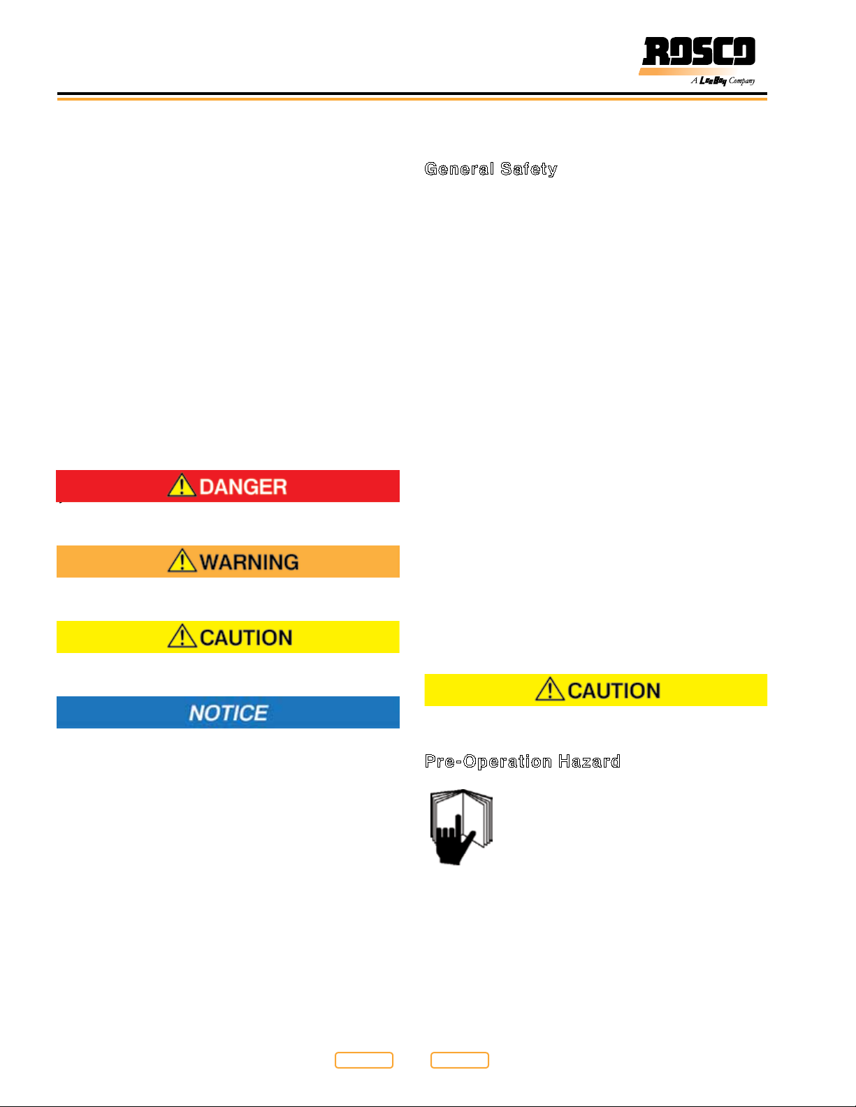
LOOK FOR THESE SYMBOLS WHICH POINT OUT
ITEMS OF EXTREME IMPORTANCE TO THE SAFETY
OF YOU AND YOUR COWORKERS. READ AND
UNDERSTAND THOROUGHLY. HEED THE WARNING
AND FOLLOW THE INSTRUCTIONS.
Keep safety labels in good condition. If safety labels
become missing or damaged, replacement safety labels
are available from your LeeBoy Dealer (see Safety
Label Locations in Section 2).
7).
Indicates a hazardous situation which, if not avoided,
will result in death or serious injury.
Safety Precautions
General Safety
• Have a rst-aid kit available and know how to use it.
• Keep a “charged” re extinguisher within reach
whenever you work in an area where re may occur.
Have the correct type of extinguisher for your situation
and know how to use it:
Type A: Wood, paper, textile and rubbish
Type B: Flammable liquids
Type C: Electrical equipment
• Do not hurry. Use recommended hand holds and
steps with at least three points of support when
getting on and off the Maximizer 3B. Keep steps, oor,
hand holds and controls clean and free from grease.
Face the machine when climbing up and down and
never jump off or dismount while the machine is in
motion. Falling from the machine can cause serious
injury.
• Do not permit riders on the Maximizer 3B. Death or
serious injury can occur if riders fall off or under the
machine while it is in motion.
Indicates a hazardous situation which, if not avoided,
could result in death or serious injury.
Indicates a hazardous situation which, if not avoided,
could result in minor or moderate injury.
Indicates a situation which can cause damage to the
equipment, personal property and/or the
environment, or cause the Rosco Maximizer 3B
Asphalt Distributor to operate improperly.
NOTE: Indicates a procedure, practice, or condition that
should be followed in order for the machine or
component to function in the manner intended.
• Do not go into the tank! Death can occur due to lack
of oxygen, breathing poisonous fumes or explosion.
Keep others out!
• Do not smoke near the machine. Fuel, emulsion and
fumes can explode when exposed to ames or heat
from smoking or other sources.
The safety messages that follow have CAUTION level
hazards.
Pre-Operation Hazard
Read and understand this Operation
Manual before operating or servicing the
engine to ensure that safe operating
practices and maintenance procedures are
followed.
• Never permit anyone to service or operate the Rosco
Maximizer 3B Asphalt Distributor without proper
training.
• Contact LeeBoy or an authorized LeeBoy Dealer for
additional training.
2-2
Return to
Thumb Index
Return to
Last Viewed
Rosco Maximizer 3B Asphalt Distributor
Page 15
Safety
• Safety signs and labels are additional reminders for
safe operating and maintenance techniques.
• Make sure you are aware of all laws and regulations
that are in effect where the machine is operated.
Ensure you have all necessary licenses to operate the
machine.
• Before starting or operating the machine, ensure all
controls are OFF or in neutral position.
• Know and understand the jobsite trafc ow patterns
and obey agmen, road signs and signals.
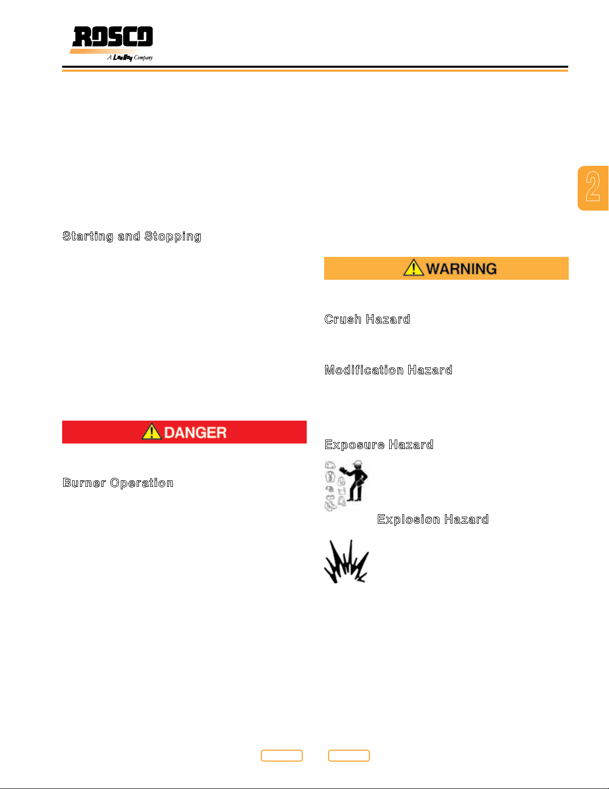
Starting and Stopping
• Walk around the machine and warn all personnel in
the area before starting the machine. Be sure the
area is clear before starting. Death or serious injury
can occur to bystanders from being crushed under a
moving machine or being hit by material.
• Always park the machine on level ground whenever
possible. Apply the parking brake. On grades, park the
Distributor with the wheels securely blocked.
• Stopping distances must be anticipated for all
conditions. If stopping on a grade, the distance
needed to come to a stop will be longer. Familiarize
yourself with these variables so you can anticipate
when a longer stopping distance is required.
• Keep the tank vents clear to avoid a buildup of
pressure in the tank when heating. Check the vents
before starting the burners.
• Never use gasoline, alcohol or any other unapproved
fuel in a diesel burner. Fire and explosion can occur.
• Do not operate the burners while the wash down
system is operating or has recently been used. Fire
and explosion can occur.
• Do not operate the burners with top tank cover open.
Fire and explosion can occur.
• Be sure to read, understand and follow all precautions
for the type of cleaning material you are using.
The safety messages that follow have WARNING
level hazards.
Crush Hazard
Keep bystanders away from work area before and
during operation.
Modification Hazard
Never modify the Rosco Maximizer 3B Asphalt
Distributor without written consent of LeeBoy. Any
modication can affect the safe operation of the
machine and may cause personal injury or death.
2
The safety messages that follow have WARNING
level hazards.
Burner Operation
• Never operate burner equipment when the vehicle is
being loaded or in transit. The ue tubes can become
exposed, causing an explosion inside the tank, or
ignite material being sprayed.
• Never operate the burners if the ue tubes are not
covered with at least 8 inches (20.32 cm) of material.
The ue tubes can become red hot and ignite the
vapors causing an explosion.
• Always park the truck so that the burners are up wind.
Some asphalt materials emit ammable vapors from
the vent that can be ignited by the burner ame and
cause an explosion.
• Never operate the burners in a conned area such
as a building or shed. Vapor build-up could cause an
explosion.
• Do not operate the burners if the tank is leaking or a
spill has occurred. Fire and explosion can occur.
Exposure Hazard
Always wear personal protective
equipment, including appropriate clothing,
gloves, work shoes, and eye and hearing
protection, as required by the task at hand.
Explosion Hazard
While the engine is running or the battery is
charging, hydrogen gas is being produced
and can be easily ignited. Keep the area
around the battery well-ventilated and keep
sparks, open ame and any other form of
ignition out of the area.
• Always disconnect the negative (-) battery cable
before servicing the machine.
• Do not start the engine by shorting the starter circuit
or by using any other starting method not stated in this
manual. Only use the starting procedure as described
in this manual to start the engine.
• Never charge a frozen battery. Always slowly warm the
battery to room temperature before charging.
Return to
Rosco Maximizer 3B Asphalt Distributor 2-3
Last Viewed
Return to
Thumb Index
Page 16
Safety
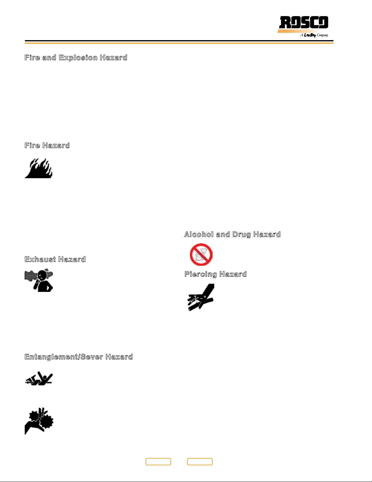
Fire and Explosion Hazard
• Diesel fuel is ammable and explosive under certain
conditions.
• Never use a shop rag to catch the fuel.
• Wipe up all spills immediately.
• Never refuel with the engine running.
• Store any containers containing fuel in a well-
ventilated area, away from any combustibles or
sources of ignition.
Fire Hazard
Have appropriate safety equipment
available. Have all re extinguishers
checked periodically for proper operation
and/or readiness.
• Always read and follow safety-related precautions
found on containers of hazardous substances
like parts cleaners, primers, sealants and sealant
removers.
• Undersized wiring systems can cause an electrical
re.
• No not leave the machine unattended. Never allow
anyone to reach into the machine while it is operating.
Exhaust Hazard
• Always stop the engine before beginning service.
• Verify that all machine guards and covers are attached
properly to the machine before starting the engine.
Do not start the engine if any guards or covers are not
properly installed on the machine.
• If you must run the engine during maintenance
procedures, make sure you have a helper to
keep bystanders clear of the machine and make
observations of moving parts as requested by the
operator.
• Always turn the start switch to the OFF position after
operation is complete and remove the key from the
switch. Keep the key in your possession when the
machine is not operating.
• Attach a “Do Not Operate” tag near the key switch
while performing maintenance on the equipment.
• Never operate the engine while wearing a headset to
listen to music or radio because it will be difcult to
hear the warning signals.
• Always start the engine or operate the controls while
you are seated in the operators seat.
Alcohol and Drug Hazard
Never operate the engine while under the
inuence of alcohol or drugs, or when ill.
All internal combustion engines create
carbon monoxide gas during operation and
special precautions are required to avoid
carbon monoxide poisoning:
• Never block windows, vents or other means of
ventilation if the Rosco Maximizer 3B Asphalt
Distributor is operating in an enclosed area.
• Always ensure that all connections are tightened to
specications after repair is made to the exhaust
system.
Entanglement/Sever Hazard
Verify there are no people, obstacles or
other equipment near the Rosco Maximizer
3B Asphalt Distributor before starting the
engine. Sound the horn as a warning
before starting the engine.
If the engine must be serviced while it is
operating, remove all jewelry, tie back long
hair and keep hands, other body parts and
clothing away from moving/rotating parts.
Piercing Hazard
Avoid skin contact with high-pressure
hydraulic uid or diesel fuel spray caused
by a hydraulic or fuel system leak. A broken
hydraulic hose or fuel injection line can
cause injury. High-pressure hydraulic uid
or fuel can penetrate your skin and result in serious
injury. If you are exposed to high-pressure hydraulic uid
or fuel spray, obtain prompt medical treatment.
• Never check for a hydraulic uid or fuel leak with your
hands. Always use a piece of wood or cardboard.
Have your authorized LeeBoy Dealer or distributor
repair the damage.
2-4
Return to
Thumb Index
Return to
Last Viewed
Rosco Maximizer 3B Asphalt Distributor
Page 17

Flying Object Hazard
Safety
Always wear eye protection when cleaning
the Rosco Maximizer 3B Asphalt Distributor
with compressed air or high-pressure
water. Dust, ying debris, compressed air,
pressurized water or steam may injure your
eyes.
Coolant Hazard
Wear eye protection and rubber gloves
when handling engine coolant. If contact
with the eyes or skin should occur, ush
eyes and wash immediately with clean
water.
Burn Hazard
Some of the machine surfaces become
very hot during operation and shortly after
shutdown.
• Keep hands and other body parts away from hot
machine surfaces.
• Handle hot components with heat-resistant gloves.
The safety messages that follow have CAUTION level
hazards.
Poor Lighting Hazard
Ensure that the work area is adequately illuminated.
Always install wire cages on portable safety lights.
Tool Hazard
Always use tools appropriate for the task at hand and
use the correct size tool for loosening or tightening
Rosco Maximizer 3B Asphalt Distributor parts.
The safety messages that follow have NOTICE level
hazards.
Any part which is found defective as a result of
inspection or any part whose measured value does not
satisfy the standard or limit must be replaced.
Always tighten components to the specied torque.
Loose parts can cause Rosco Maximizer 3B Asphalt
Distributor damage or cause it to operate improperly.
Only use replacement parts approved by LeeBoy. Other
replacement parts may affect warranty coverage.
Follow the guidelines of the EPA or other
governmental agencies for the proper
disposal of hazardous materials such as
engine oil, diesel fuel and engine coolant.
Consult local authorities or reclamation
facility.
• Clean all accumulated dirt and debris away from
the body of the machine and its components before
you inspect the machine or perform preventive
maintenance procedures or repairs. Operating
a machine with accumulated dirt and debris will
cause premature wear of machine components.
Accumulated dirt and debris also hinders effective
machine inspection.
• Retrieve any tools or parts that may have dropped
inside of the machine to avoid improper machine
operation.
• Dispose of hazardous materials in accordance with
all applicable laws and regulations. Never dispose of
hazardous materials by dumping them into a sewer, on
the ground, or into groundwater or waterways.
• If any alert indicator illuminates during machine
operation, stop the engine immediately. Determine
the cause and repair the problem before continuing to
operate the machine.
2
Return to
Rosco Maximizer 3B Asphalt Distributor 2-5
Last Viewed
Return to
Thumb Index
Page 18
Safety
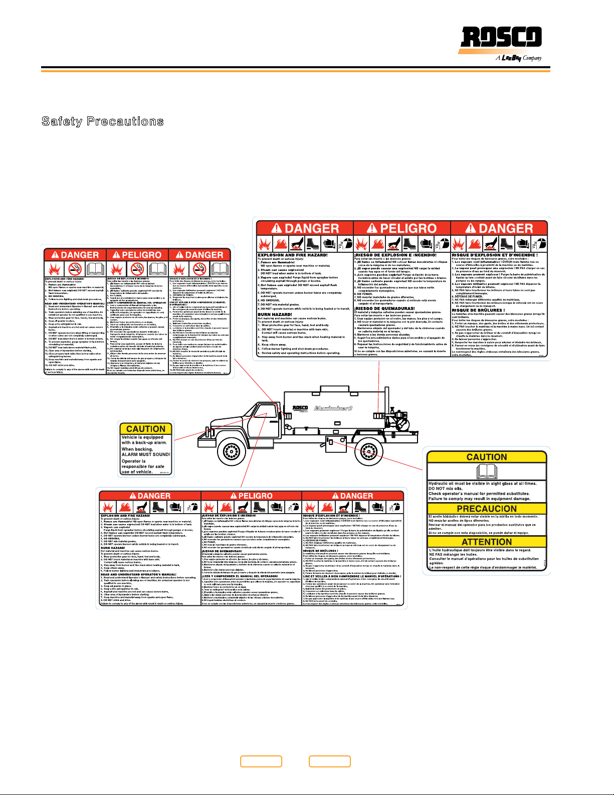
Safety Label Locations
Safety Precautions
If your machine has been repainted, it is extremely
important that all the decals referring to CAUTION,
WARNING, and DANGER be replaced in their proper
locations. The illustrations on this page will aid you in
determining the proper locations. For additional help,
you should refer to the parts listing in the parts section
of this manual and note the description column.
A description of location is provided below for each
safety label. For additional instructions, contact your
dealer (see Safety Label Installation in Section 7).
NOTE: It is the responsibility of the owner and operator
to make sure that all safety labels are readable
and located on machine as designated by
LeeBoy.
2-6
Safety Labels and Safety Label Locations
Figure 2-1
Return to
Thumb Index
Return to
Last Viewed
Rosco Maximizer 3B Asphalt Distributor
Page 19
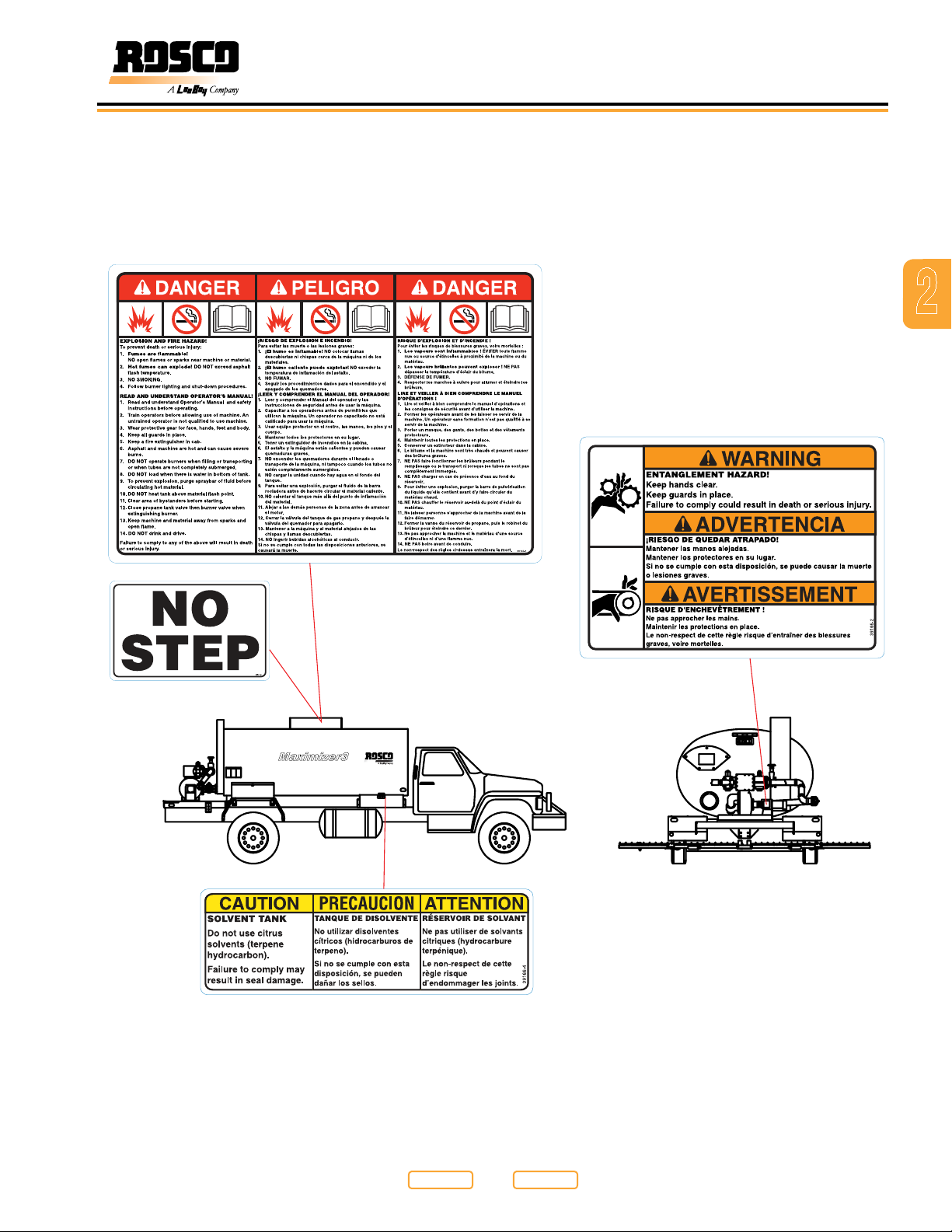
Safety
2
Safety Labels and Safety Label Locations
Figure 2-2
Return to
Rosco Maximizer 3B Asphalt Distributor 2-7
Last Viewed
Return to
Thumb Index
Page 20

Safety
NOTES
2-8
Return to
Thumb Index
Return to
Last Viewed
Rosco Maximizer 3B Asphalt Distributor
Page 21

Section 3
General Information
Page
General Information . . . . . . . . . . . . . . . . . . . . . . . . . . . . . 3-1
Limited Warranty Policy . . . . . . . . . . . . . . . . . . . . . . . . . . 3-2
Warranty . . . . . . . . . . . . . . . . . . . . . . . . . . . . . . . 3-2
Limitations . . . . . . . . . . . . . . . . . . . . . . . . . . . . . . 3-2
Items Not Covered . . . . . . . . . . . . . . . . . . . . . . . . . . 3-3
Other Limitations . . . . . . . . . . . . . . . . . . . . . . . . . . . 3-3
Contact Information . . . . . . . . . . . . . . . . . . . . . . . . . . . . 3-4
Record of Ownership . . . . . . . . . . . . . . . . . . . . . . . . . . . 3-4
Nameplate . . . . . . . . . . . . . . . . . . . . . . . . . . . . . . . . . 3-4
Return to
Rosco Maximizer 3B Asphalt Distributor 3-1
Last Viewed
Return to
Thumb Index
Page 22

General Information
Limited Warranty Policy
Warranty
1. Subject to the limitations, exclusions, and claims
procedures set forth herein, LeeBoy warrants [to
the rst retail purchaser] that this product will be
free from [substantial] defects in materials and
workmanship during the warranty period.
2. If a defect in material or workmanship is found, your
authorized LeeBoy Dealer is to be notied during
the warranty period. LeeBoy and its authorized
Dealer will repair or replace any part or component
of the unit or part that fails to conform to the
warranty during the warranty period.
3. The warranty period will begin on the initial start-up,
training and delivery of the unit by the Dealer to the
customer, and will expire after twelve (12) months
following the delivery of the machine to the rst retail
purchaser. (See Dealer for additional warranty.)
4. Manufacturers’ Warranties: Engines are warranted
by their manufacturers and may have warranty
coverage that differs from that of LeeBoy. LeeBoy
does not warrant any engine.
5. Replacement parts furnished by LeeBoy are
covered for the remainder of the warranty period
applicable to the unit or component in which such
parts are installed.
6. LeeBoy has the right to repair any component or
part before replacing it with a new one.
7. All new replacement parts purchased by a LeeBoy
Dealer will carry a six-month warranty.
8. This Limited Warranty is governed by the laws of the
State of North Carolina.
THE FOREGOING WARRANTY IS EXCLUSIVE AND
IN LIEU OF ALL OTHER EXPRESSED, STATUTORY
AND IMPLIED WARRANTIES APPLICABLE TO
UNITS, ENGINES, OR PARTS INCLUDING WITHOUT
LIMITATION, ALL IMPLIED WARRANTIES OF
MERCHANTABILITY OR FITNESS FOR ANY
PARTICULAR USE OR PURPOSE OR AGAINST
INFRINGEMENT.
Limitations
LeeBoy has no obligation for:
1. Any defects caused by misuse, misapplication,
negligence, accident or failure to maintain or use
in accordance with the most current operating
instructions.
2. Unauthorized alterations.
3. Defects or failures caused by any replacement
parts or attachments not manufactured by or
approved by LeeBoy.
4. Failure to conduct normal maintenance and
operating service including, without limitation,
providing lubricants, coolant, fuel, tune-ups,
inspections or adjustments.
5. Unreasonable delay, as established by LeeBoy, in
making the applicable units or parts available upon
notication of a service notice ordered by same.
6. Warranty Responsibility: The warranty responsibility
on all engines rests with the manufacturer of the
engine.
7. Warranty and Parts Support: LeeBoy may
have support agreements with some engine
manufacturers for warranty and parts support.
However, LeeBoy does not warrant the engine.
8. This Limited Warranty sets forth your sole remedy
in connection with the sale or use of the LeeBoy
product covered by this Limited Warranty.
9. This Limited Warranty extends only to the rst retail
purchaser, and is not transferable.
10. In the event any portion of this Limited Warranty
shall be determined to be invalid under any
applicable law, such provision shall be deemed null
and void and the remainder of the Limited Warranty
shall continue in full force and effect.
3-2
Return to
Thumb Index
Return to
Last Viewed
Rosco Maximizer 3B Asphalt Distributor
Page 23

General Information
Items Not Covered
LeeBoy is not responsible for the following:
1. All used units or used parts of any kind.
2. Repairs due to normal wear and tear or brought
about by abuse or lack of maintenance of the
Machine.
3. Attachments not manufactured or installed by
LeeBoy.
4. Liability for incidental or consequential damages of
any type including, but not limited to, lost prots or
expenses of acquiring replacement equipment.
Other Limitations
IN NO EVENT, WHETHER AS A RESULT OF BREACH
OF CONTRACT OR WARRANTY OR ALLEGED
NEGLIGENCE OR LIABILITY WITHOUT FAULT, SHALL
LEEBOY BE LIABLE FOR SPECIAL, INCIDENTAL OR
CONSEQUENTIAL DAMAGES INCLUDING, WITHOUT
LIMITATION, LOSS OF PROFIT OR REVENUE, COST
OF CAPITAL, COST OF SUBSTITUTED EQUIPMENT,
FACILITIES OR SERVICES, DOWNTIME COSTS,
LABOR COSTS OR CLAIMS OF CUSTOMERS,
PURCHASERS OR LESSEES FOR SUCH DAMAGES.
IN NO EVENT WILL WARRANTY COMPENSATION,
OR OTHER DAMAGES AVAILABLE FROM LEEBOY,
EXCEED THE PURCHASE PRICE OF THE PRODUCT.
3
Return to
Rosco Maximizer 3B Asphalt Distributor 3-3
Last Viewed
Return to
Thumb Index
Page 24
General Information
Contact Information
For information regarding parts and repairs about your
LeeBoy product, rst contact the dealer you purchased
your product from.
Sales Representative:
Dealership Name:
Dealership Address:
Dealership Phone:
Record of Ownership
Please ll out the following information and use it
when you need to contact LeeBoy for service, parts or
literature.
Machine Model Number:
Machine Serial Number:
Date of Purchase:
Nameplate
If you have a persistent problem your dealer is unable to
resolve, contact LeeBoy directly.
Record dealer information in the space provided.
For additional information about LeeBoy, please visit:
www.leeboy.com.
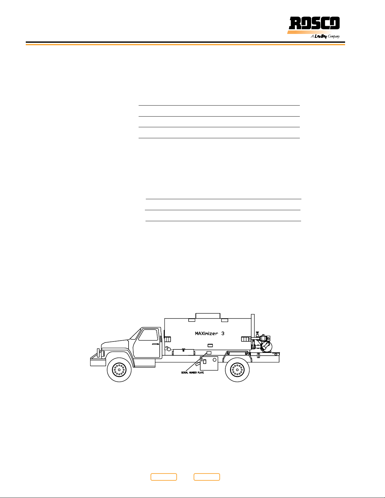
Nameplate (Figure 3-1) contains the specic model number and serial number used to identify the components for any parts or service information.
Nameplate Location
Figure 3-1
3-4
Return to
Thumb Index
Return to
Last Viewed
Rosco Maximizer 3B Asphalt Distributor
Page 25

Section 4
Specifications
Page
Specications . . . . . . . . . . . . . . . . . . . . . . . . . . . . . . . . 4-1
General Information . . . . . . . . . . . . . . . . . . . . . . . . . . . . 4-2
General . . . . . . . . . . . . . . . . . . . . . . . . . . . . . . . 4-2
System Overview . . . . . . . . . . . . . . . . . . . . . . . . . . 4-2
Circulating System . . . . . . . . . . . . . . . . . . . . . . . . . . 4-2
Burner System . . . . . . . . . . . . . . . . . . . . . . . . . . . . 4-3
Plus One Controller . . . . . . . . . . . . . . . . . . . . . . . . . 4-3
In-Cab Operator System . . . . . . . . . . . . . . . . . . . . . . . 4-3
Material Considerations . . . . . . . . . . . . . . . . . . . . . . . 4-4
Specication Tables . . . . . . . . . . . . . . . . . . . . . . . . . . . . 4-6
Torque Specs . . . . . . . . . . . . . . . . . . . . . . . . . . . . . . . 4-10
Metric Fasteners . . . . . . . . . . . . . . . . . . . . . . . . . . . 4-10
Inch Fasteners . . . . . . . . . . . . . . . . . . . . . . . . . . . . 4-11
Hydraulic Fittings . . . . . . . . . . . . . . . . . . . . . . . . . .4-12
Full Torque Nut Coupling Installation . . . . . . . . . . . . . . . . . 4-12
Return to
Rosco Maximizer 3B Asphalt Distributor 4-1
Last Viewed
Return to
Thumb Index
Page 26
Specications
General Information
The descriptions and specications provided in this
section are applicable to the Rosco Maximizer 3B
Asphalt Distributor.
This section contains a description of how the major
components operate. It also includes specications for
the major system components. Included in this section
are machine weights, dimensions, performance, and
major system specications for the machine.
General
The Rosco Maximizer 3B Asphalt Distributor is used
for the transportation and distribution of asphalt-based
products for road maintenance and repair. The machine
can spray asphalt emulsions, asphalt cements and
cutback asphalts. LeeBoy strongly recommends the
use of asphalt emulsions. Water based emulsions
reduce the risk of re and explosion.
The Maximizer 3B should not be used
to distribute water, calcium chloride or other deicing liquids. These materials can corrode the pump
and valves and dangerously contaminate the tank.
If these materials are used in a Maximizer 3B, the
warranty is voided on those components affected by
the material.
System Overview
The Maximizer 3B consists of a truck-mounted insulated
tank ranging in capacity from 1,000 to 4,000 gal. (3,785
to 15,142 liters). ROSCO Distributors are equipped with
a heating system that will maintain the asphalt at the
proper spray temperature.
The Distributor has a power driven asphalt pump
capable of handling products ranging from light
applications of emulsied asphalt to heavy asphalt
cements heated to spraying viscosity. At the back of
the tank is a system of spraybars with nozzles through
which asphalt is forced under pressure and applied to
the road surface. The spraybars cover widths ranging
from 4 in. to 20 ft. (10 cm to 6.1 m) in one pass.
Circulating System
The circulating system has an engine driven hydraulic
pump which drives the hydraulic motor. The hydraulic
motor powers the asphalt pump, allowing the pump to:
• ll the distributor tank
• circulate material through the bar and tank
• spray material through the bar or hand spray
• draw material back to the tank from the bar or hand
spray
• pump material from the tank to outside storage
• transfer material from one storage tank to another
The spraybar must have a constant and uniform
pressure along the entire length of the bar for uniform
output at each nozzle.
The Rosco Maximizer 3B Asphalt Distributor delivers a
volume of asphalt to the spraybar which is regulated by
a number of variables, including:
• asphalt pump speed
• application rate setting
• truck speed
• spraybar width
The on-board computer senses the different values and
controls the asphalt pump speed to deliver the precise
amount of asphalt to the spraybar.
Both the application rate and spray pattern are
inuenced by factors such as the selected application
rate, the truck speed and nozzle size.
If the nozzles are too small for the application rate and
truck speed, the liquid will atomize, the spray pattern
will distort and the result will be excessive over-spray
or inconsistent application rate. If the nozzles are
too large, the result will be streaking caused by low
spraybar pressure (see Valves And Nozzles in Section
6).
The circulating system and the burner system are
the main systems on the Maximizer 3B. Read these
sections so you are aware of the functions and
capabilities of the unit and its systems.
Return to
4-2
Thumb Index
Return to
Last Viewed
Rosco Maximizer 3B Asphalt Distributor
Page 27
Specications
Burner System
USE BURNERS PROPERLY! Burners are used to
increase the temperature of liquid asphalt material to
the correct spraying temperatures. The burners should
only be used while the liquid asphalt material is being
circulated in the tank.
If the material has cooled to the point
that it will not ow easily and will not circulate, the
operator must use extra care. Improper heating will
cause damage to the equipment and the material
being heated.
The burners in the Maximizer 3B have a very high
heat output which must be dissipated through the
asphalt. Asphalt is an excellent insulator and resists the
conduction of heat through the material.
If the material is heated too hot or too quickly without
the proper circulation, hot spots will be created near the
rear of the tank at the ue tubes. This will damage the
ue tubes and cause a break down of the material.
Operating the burners without
circulating the product can create explosive fumes.
If the product can not be circulated after 15 minutes
of heating, the fuel to the burners must be turned off,
while leaving the blowers running. Do not try to heat
material again for 30 minutes.
If it is necessary to heat asphalt that has cooled more
than 20 to 30 degrees below the optimum spraying
temperature, the operator must use extreme care in
reheating the material.
Run the burners for short periods of
time (15 minutes ON, 15 minutes OFF) to allow the
heat to dissipate through the material. This will
prevent damage to the ue liner.
The amount of time necessary to heat the asphalt
material to allow proper circulation and heating will
vary depending on the type of material, the type of
burners, the tank size and the amount of material in the
tank. If you have any doubts about the proper way to
heat cooled asphalt, contact your asphalt supplier or
equipment manufacturer.
The Burners are located at the left rear of the Maximizer
3B. The ame from the burner is directed through
the re tubes along the bottom of the tank. Diesel or
propane can be used as fuel, depending on the burner
option specied.
Never operate the burners without rst reviewing the
instructions.
Plus One Controller
The Plus One system is used to automatically control
the application rate of the asphalt distributor truck. It is
capable of automatically maintaining constant asphalt
application rates regardless of changes in distributor
speed and spraybar width. The controller has on/off
toggle switches to provide spray nozzle control along
the spraybar in 1 foot (.3 m) increments.
Distributor functions are set by selecting one of eight
modes of operation. Each mode of operation denes
the behavior of the automatic asphalt valves and the
spraybar valves for the distributor function selected. A
software memory feature is included to store up to 12
user dened presets of operating parameters for quick
setup of application rates and speed calibrations.
Selectable readouts on the in-cab control panel display
the following in real time; distributor ground speed (fpm),
asphalt spray rate (gpm), total distance sprayed (ft), total
gallons sprayed (gal), total area sprayed (sq.yd.), ow
& speed calibration application rate (gal/sq.yd.), tank
temperature (degree F), hour meter (hr), and spraybar
length (ft).
The controller uses either a GPS Speed Sensor or
an (optional) Radar Horn Speed Sensor to measure
distributor ground speed necessary for application rate
calculations and real time display of distributor metrics.
Rear controls are located in the tool box on the right
hand side rear fender and are used to control asphalt
pump speed, asphalt pump direction, spraybar hydraulic
functions and the optional washdown pump when rear
control priority is selected.
In-Cab Operator System
The main console located in the truck cab contains a
DP610 color display and utilizes a toggle switch system
for Maximizer 3B spraybar control. Truck control
parameters and modes of operation are selected
through the DP610 display using programmable soft
keys. Setup functions and real time monitoring functions
are stored and processed in the DP610.
In addition, the console includes a Master Power ON/
OFF toggle switch, Burner switch, and potentiometer for
the control of asphalt pump speed and direction when
in MANUAL mode and front control priority. Parameters
are used to congure options installed on specic trucks
as well as increase memory and data storage capacity.
A CAN signal allows communication between the In-Cab
Controller and the control modules located in the valve
box at the rear of the truck.
4
Return to
Rosco Maximizer 3B Asphalt Distributor 4-3
Last Viewed
Return to
Thumb Index
Page 28

Specications
Material Considerations
NOTE: All information in the Material Considerations
section was obtained from publications of the
Asphalt Institute.
This section will help the operator better understand the
properties of the asphalt product being used (see Table
4-4. Guideline Temperatures For Liquid Asphalts).
The selection of the right product is generally
dependent on the following considerations:
1. Availability of various types of aggregate.
2. Availability of various liquid asphalt grades.
3. Climate conditions during applications.
4. Trafc conditions during application.
5. Contract specications.
NOTE: The information given in the charts in this section
is based on industry standards. It is important to
note that some asphalt product manufacturers
have grades or mixtures which do not conform
to industry standards. These materials are often
tailored to local conditions and may provide
superior performance to standard grades.
There are many types and grades of asphalt products.
The best results can be obtained through the trial of
several different types of asphalt and aggregates. The
following classications and grades of asphalts are
provided to help in the selection.
Asphalt Cement (AC):
Cutback Asphalt:
• An asphalt cement which has been liqueed by
blending with petroleum solvents. Upon exposure to
the air, the solvents evaporate, leaving the asphalt
cement to perform its function of cementing and
waterproong.
When using cutback asphalts, extreme
caution must be used to prevent re or explosion. Do
not use open ames or sparks near these materials.
Use controlled heat only. Never use open ames to
examine tanks in which these materials have been
used or stored. Be sure all vehicles transporting
these materials are properly vented. Allow only
experienced personnel to handle these materials.
Be sure all applicable interstate and intrastate
commerce requirements are met.
Cutback asphalts are divided into three main grades.
1. Rapid Curing (RC) Asphalt: A cutback asphalt of
high volatility composed of asphalt cement using
naphtha or gasoline-type dilutant.
2. Medium Curing (MC) Asphalt: Cutback asphalt of
medium volatility composed of asphalt cement and
kerosene-type dilutant.
3. Slow Curing (SC) Asphalt: A cutback asphalt of low
volatility composed of asphalt cement and oils.
It is important to remember that
cutback asphalts are often used at temperatures
above their ash points. Serious injury can occur
from burns.
• Asphalt that is rened to meet specications for
paving, industrial, and special purposes.
Return to
4-4
Thumb Index
Return to
Last Viewed
Rosco Maximizer 3B Asphalt Distributor
Page 29

Specications
Emulsified Asphalt:
• An emulsion of asphalt cement and water with a small
amount of an emulsifying agent. The emulsifying agent
determines the charge of the asphalt particles. It may
have a negative (-) charge called anionic, or a positive
(+) charge called cationic.
NOTE: An anionic type of emulsion will work best with
aggregates having positive (+) surface charges
such as limestone and dolomite.
A cationic type of emulsion will work best with
aggregates having negative (-) surface charges
such as siliceous or granitic aggregates.
DO NOT mix emulsion types,
especially anionic with cationic.
Standard grades of Emulsied Asphalt are:
Anionic (- charge):
• RS-1, RS-2, MS-1, MS-2, MS-2h, HFMS-1, HFMS-2,
HFMS-2h, HFMS-2s, SS-1, SS-1h.
Cationic (+ charge):
• CRS-1, CRS-2, CMS-2, CMS-2h, CSS-1, CSS-1h.
• RS, MS, SS: Indicate the emulsion setting rate. (Rapid
Set, Medium Set, Slow Set)
• h, s: Indicate if a hard or soft base asphalt is used in
the mix.
Contamination
It is very important to remember that when you are
loading a new material into the Maximizer, you must
be sure that the new material is compatible with the
residual material in the tank. The safest thing to do is
to completely clean out the tank and the entire system.
Total clean out is essential if you are not sure of the last
material that was used in the unit.
However, some materials can be loaded with a small
residual amount (0.5 % of capacity or less) of the
previous material remaining in the tank, (see Guide For
Loading Asphalt Products in Section 4).
To reduce the risks of re or explosion, follow Table
4-5. Guide For Loading Asphalt Products to eliminate
contamination.
When incompatible materials are mixed, it can increase
the possibility that the material will not meet the job
specications. More importantly, mixing materials can
increase the risk of re or explosion. For example, light
hydrocarbons may be present in a tank from previous
loads or from diesel oil or solvents used in cleaning the
tank.
Be sure the tank has no water in it
before loading. Hot material will turn water into
steam and can cause an explosion.
4
• HF: Indicates High-Float which means chemicals have
been added to permit a thicker lm of asphalt on the
aggregate particles to prevent drain off of asphalt
from the aggregate.
• C: Indicates a cationic asphalt. The absence of the
letter “C” means it is anionic asphalt.
Viscosity
Viscosity is a uid’s resistance to ow (how thick and
gluey a uid is). The recommended viscosity for spraying
with a distributor is 25 to 50 Saybolt Furol seconds (45 -
100 Centistokes Kinematic Viscosity).
The recommended viscosity for loading or pumping
is a maximum of 400 Saybolt Furol seconds (800
Centistokes Kinematic Viscosity).
Viscosities above these ranges will limit the
performance of the machine. Your asphalt provider will
be able to tell you the viscosity of your product.
Return to
Rosco Maximizer 3B Asphalt Distributor 4-5
Last Viewed
Return to
Thumb Index
Page 30

Specications
Specification Tables
The specications provided in this section are
applicable to the Rosco Maximizer 3B Asphalt
Distributor. Included in this section are dimensions,
performance, and torque values for both metric and
standard inch fasteners.
Replace original equipment only with
LeeBoy approved components.
Table 4-1. Tank Specication Table
ITEM SPECIFICATION
Tank Capacity 1000 U.S. gallons (3,785 L) to 4000 U.S. gallons (15,142
L) with overage for expansion.
Tank Meets all applicable Federal DOT tank regulations.
Elliptical shape. 10 gauge (3 mm) shell and 7 gauge
(4.5 mm) at heads, anged reinforced and welded to
shell inside & and outside of tank. All seams electrically
welded.
Shell 10 GA, elliptical shape shell. 7 GA at heads, ange
reinforced and electrically welded to shell inside and
outside of tank.
Thermometers Armored pencil inspector’s type 50° F to 500° F (10° C
to 260° C) and 5 inch (127 mm) dial type 50° F to 500°
F (10° C to 260° C) mounted on front left side of tank in
pipe well. Tank temperature sensor, located at rear of
tank, displayed on color display of in-cab controller.
Full Surge Plates 10 gauge (3 mm) steel with staggered openings.
Insulation 2 inch (51 mm) rock wool with spacers to prevent
compression, and clips to secure position of insulation.
Weatherproof aluminum jacket.
Top Opening 22 inch (558 mm) diameter with weather tight and safety
relieving cover. Inside splash guards, 3 inch (76 mm)
diameter, steel measuring stick, basket type strainer,
overow pipe, and tank vent.
Sump 8 inch (203 mm) diameter at rear of tank with 4 inch (102
mm) clean-cut plug. Suction line from pump includes
tank cut-off valve.
Heating System Double ue with 8 inch (203 mm) inside diameter tubing.
Exhaust Stack Stainless steel with rain cover.
Burners Dual diesel red burner with electronic ignition and heat
limit controls. Dual, U-type high-temperature ue pipe
running the length of the tank.
Asphalt Pump Viking 400 GPM (1514 LPM) capacity, rotary gear pump
with built in relief valve for safety. Located at rear of unit
with suction piping to tank sump. Driven by low-speed,
high-torque, xed displacement hydraulic motor.
Distributing Lines High-temperature, exible metal hoses.
Clean Out Connection to asphalt pump for clean-out of pump and
piping. 25 gallon (94.6 L) ush tank.
4-6
Return to
Thumb Index
Return to
Last Viewed
Rosco Maximizer 3B Asphalt Distributor
Page 31

Specications
Table 4-1. Tank Specication Table (continued)
ITEM SPECIFICATION
Spray System 16 foot (4.9 m) full circulating, extendable spraybar,
comprised of two 8 foot (2.4 m) independently
controlled spraybar sections. When in spray mode and
if corresponding nozzle enable switches are enacted
each nozzle turns on when the spraybar is extended and
turns off when retracted. All functions operated by the
Plus One Controller in the cab.
Nozzles and Valves Brass, slotted nozzles. Non-clogging system. Manual
valve actuators allow the operator to control spray in 4
inch (10.16 cm) increments as the spraybar extends and
retracts.
Table 4-2. Controller Specication Table
ITEM SPECIFICATION
Controller Plus One Controller works with electronic pump speed
control to govern the application rate according to the
distributor speed and spraybar width. Provides On/Off
control of spray nozzles in 1 foot (.3 m) increments. 4
inch (10.16 cm) nozzle control is possible with spraybar
extension and retraction. Memory feature capable of
storing 12 preset application rates included. Provides
readouts for speed (FPM), pump ow (GPM), total
asphalt sprayed (gallons), total area covered (square
yards), tank temperature, total run time meter (hours),
spraybar width (feet and inches). System includes GPS
speed sensor and rear mounted controls for manual
control of asphalt pump speed and direction as well as
hydraulic spraybar functions.
4
Return to
Rosco Maximizer 3B Asphalt Distributor 4-7
Last Viewed
Return to
Thumb Index
Page 32

Specications
Table 4-3. Additional Standard and Optional Equipment Specication Table
STANDARD OPTIONAL
Handspray gun with 25 foot (7.6 m) hose PTO driven hydraulic pump from truck transmission
Front and rear dial contents gauge Outre protection on diesel burner
Sampling valve LPG burner in lieu of diesel burner
ICC clearance lights and reectors Portable LP torch with pressure regulators and
connections to frame mounted 52 gallon (197 L) tank
Back up alarm Low density electric heat
Rear bumper and a 4-way mirror Washdown system with pump and hose for cleaning the
spraybar
Mud aps Hose reel for the washdown hose
Ladder and platform assembly Loading hose 3 inch by 15 foot (7.6 cm X 4.6 m) exible
steel with quick couplers
Grease gun Loading hose 3 inch by 15 foot (7.6 cm X 4.6 m) rubber
with quick couplers
Enviro-Flush recirculating clean-out system 18 foot (5.5 m) spraybar system
20 foot (6.1 m) spraybar system
Radar Horn Speed Sensor (option in lieu of GPS)
Table 4-4. Guideline Temperatures For Liquid Asphalts
TYPE & GRADE SPRAY TEMP STORE TEMP MIN FLASH POINT
Asphalt Cements °C °F °C °F °C °F
AC -2.5 130+ 270+ 160 320 163 325
AC-5 140+ 280+ 166 330 177 350
AC-10 140+ 280+ 174 345 219 425
AC-20 145+ 295+ 177 350 232 450
AC-40 150+ 300+ 177 350 232 450
AR-1000 135+ 275+ 163 325 205 400
AR-2000 140+ 285+ 168 325 219 425
AR-4000 145+ 290+ 177 350 227 440
AR-8000 145+ 290+ 177 350 232 450
PEN 40-50 150+ 300+ 177 350 232 450
PEN 60-70 145+ 295+ 177 350 232 450
PEN 85-100 140+ 280+ 177 350 232 450
PEN 120-150 130+ 270+ 177 350 219 425
PEN 200-300 130+ 270+ 168 335 177 350
4-8
Return to
Thumb Index
Return to
Last Viewed
Rosco Maximizer 3B Asphalt Distributor
Page 33

Specications
Table 4-4. Guideline Temperatures For Liquid Asphalts (continued)
TYPE & GRADE SPRAY TEMP STORE TEMP MIN FLASH POINT
Emulsied Asphalts °C °F °C °F °C °F
MC-30 30+ 80+ 54 130 38 100
MC-70 50+ 120+ 71 160 38 150
MC-250 75+ 165+ 91 195 66 150
MC-800 95+ 200+ 99 210 66 150
MC-3000 110+ 230+ 99 210 66 150
RC-70 50+ 120+ 71 160 - RC-250 75+ 165+ 91 195 27 80
RC-800 95+ 200+ 99 210 27 80
RC-3000 110+ 230+ 99 210 27 80
SC-70 50+ 120+ 71 160 66 150
SC-250 75+ 165+ 91 195 79 175
SC-800 95+ 200+ 99 210 93 200
SC-3000 110+ 230+ 99 210 107 225
RS-1 20 - 60 70 - 140 20 - 60 70 - 140
RS-2 50 - 85 125 - 185 50 - 85 125 - 185
HFRS-2 50 - 85 125 - 185 50 - 85 125 - 185
MS-1 20 - 70 70 - 160 10 - 60 50 - 140
MS-2 20 - 70 70 - 160 50 - 85 125 - 185
MS-2h 20 - 70 70 - 160 50 - 85 125 - 185
HFMS-1 20 - 70 70 - 160 10 - 60 50 - 140
HFMS-2 20 - 70 70 - 160 50 - 85 125 - 185
HFMS-2h 20 - 70 70 - 160 50 - 85 125 - 185
HFMS-2s 20 - 70 70 - 160 50 - 85 125 - 185
SS-1 20 - 70 70 - 160 10 - 60 50 - 140
SS-1h 20 - 70 70 - 160 10 - 60 50 - 140
CRS-1 50 - 85 125 - 185 50 - 85 125 - 185
CRS-2 50 - 85 125 - 185 50 - 85 125 - 185
CMS-2 20 - 70 70 - 160 50 - 85 125 - 185
4
CMS-2h 20 - 70 70 - 160 50 - 85 125 - 185
CSS-1 20 - 70 70 - 160 10 - 60 50 - 140
CSS-1h 20 - 70 70 - 160 10 - 60 50 - 140
Return to
Rosco Maximizer 3B Asphalt Distributor 4-9
Last Viewed
Return to
Thumb Index
Page 34

Specications
Table 4-5. Guide For Loading Asphalt Products
PRODUCT TO BE LOADED
LAST PRODUCT IN
TANK
Asphalt Cement OK to load Ok to load Empty to no
Cutaback Cement * Empty Tank Ok to load Empty to no
Cationic Emulsion * Empty Tank Empty to no
Anionic Emulsion * Empty Tank Empty to no
Crude Petroleum and
Residual Fuel Oils
Any Product not
listed above
ASPHALT CEMENT
* Empty Tank Empty to no
Tank must be
cleaned
CUTBACK
ASPHALT
measurable quantity
measurable quantity
measurable quantity
Tank must be
cleaned
CATIONIC
EMULSION
measurable quantity
measurable quantity
Ok to load Empty to no
Empty to no
measurable quantity
Empty to no
measurable quantity
Tank must be
cleaned
ANIONIC
EMULSION
Empty to no
measurable quantity
Empty to no
measurable quantity
measurable quantity
Ok to load
Empty to no
measurable quantity
Tank must be
cleaned
*
Torque Specs
Metric Fasteners
for standard hardware and are intended as a guide
for average application involving typical stresses
NOMINAL SIZE
& PITCH
M4 x 0.7 2.27 1.70 3.07 2.30 2.27 2.31 4.17 3.13
M5 x 0.8 4.58 3.43 6.20 4.65 6.22 4.67 8.43 6.33
M6 x 1 7.75 5.83 10.5 7.90 10.60 7.97 14.3 10.8
M8 x 1.25 18.89 14.17 25.6 19.2 18.95 19.26 34.8 26.1
M10 x 1.25 39.11 29.52 53.0 40.1 53.87 40.59 73.0 55.0
M12 x 1.75 64.94 48.71 88.0 66.0 88.56 66.42 120.0 90.0
M14 x 2 103.32 77.49 140.0 105.0 140.22 107.01 190.0 145.0
M16 x 2 162.36 121.77 220.0 165.0 221.40 166.05 300.0 225.0
M20 x 2.5 317.34 236.16 430.0 320.0 428.04 321.03 580.0 435.0
M24 x 3 516.12 409.59 740.0 555.0 754.38 557.19 1010.0 755.0
M27 x 3 797.04 597.78 1080.0 810.0 1084.86 811.80 1470.0 1100.0
M30 x 3.5 1084.86 811.80 1470.0 1100.0 1476.00 1107.00 2000.0 1500.0
Any material remaining in tank will produce dangerous conditions.
and machined surfaces. Values are based on
physical limitations of clean, plated and lubricated
hardware. In all cases, when an individual torque
value is specied, it should be followed instead of
The following Table lists torque values
Table 4-6. Torque Specications For Metric Fasteners
CLASS 8.8 [GRADE 5 EQUIVALENT] CLASS 10.9 [GRADE 8 EQUIVALENT]
TORQUE FT. LBS. TORQUE N•m TORQUE FT. LBS. TORQUE N•m
Dry Lubed Dry Lubed Dry Lubed Dry Lubed
values given in this table.
Replace original equipment with
hardware of equal grade.
4-10
Return to
Thumb Index
Return to
Last Viewed
Rosco Maximizer 3B Asphalt Distributor
Page 35

Specications
Inch Fasteners
The following Table lists torque values
for standard hardware and are intended as a guide
for average application involving typical stresses
and machined surfaces. Values are based on
Table 4-7. Torque Specications For Standard Inch Fasteners
CAPSCREWS: SAE GRADE 5 CAPSCREWS: SAE GRADE 8
SIZE THREAD TORQUE FT. LBS. TORQUE N•m TORQUE FT. LBS. TORQUE N•m
Dry Lubed Dry Lubed Dry Lubed Dry Lubed
1/4 20 UNC 8 6 11 9 12 9 16 12
28 UNF 10 7 13 10 14 10 19 14
5/16 18 UNC 17 13 24 18 25 18 33 25
24 UNF 19 14 26 20 27 20 37 28
3/8 16 UNC 31 23 42 31 44 33 59 44
24 UNF 35 26 47 36 49 37 67 50
7/16 14 UNC 49 37 67 50 70 52 95 71
20 UNF 55 41 75 56 78 58 105 79
1/2 13 UNC 75 57 100 77 105 80 145 110
20 UNF 85 64 115 86 120 90 165 120
9/16 12 UNC 110 82 145 110 155 115 210 155
18 UNF 120 91 165 125 170 130 230 175
5/8 11 UNC 150 115 205 155 210 160 285 215
18 UNF 170 130 230 175 240 180 325 245
3/4 10 UNC 265 200 360 270 375 280 510 380
16 UNF 295 225 405 300 420 315 570 425
7/8 9 UNC 430 320 580 435 605 455 820 615
14 UNF 475 355 640 480 670 500 905 680
1 8 UNC 645 485 875 655 910 680 1230 925
14 UNF 720 540 980 735 1020 765 1380 1040
1-1/8 7 UNC 795 595 1080 805 1290 965 1750 1310
12 UNF 890 670 1210 905 1440 1080 1960 1470
1-1/4 7 UNC 1120 840 1520 1140 1820 1360 2460 1850
12 UNF 1240 930 1680 1260 2010 1500 2730 2050
1-3/8 6 UNC 1470 1100 1990 1490 2380 1780 3230 2420
12 UNF 1670 1250 2270 1700 2710 2040 3680 2760
1-1/2 6 UNC 1950 1460 2640 1980 3160 2370 4290 3210
12 UNF 2190 1650 2970 2230 3560 2670 4820 3620
physical limitations of clean, plated and lubricated
hardware. In all cases, when an individual torque
value is specied, it should be followed instead of
values given in this table.
Replace original equipment with
hardware of equal grade.
4
Return to
Rosco Maximizer 3B Asphalt Distributor 4-11
Last Viewed
Return to
Thumb Index
Page 36

Specications
Hydraulic Fittings
Tightening Flare Type Tube Fittings
1. Check the are and are seat for defects that might
cause leakage.
2. Align tube with tting before tightening.
3. Lubricate connection and hand tighten swivel nut
until snug.
Table 4-8. Torque Specications For Flare Type Tube Fittings
NUT SIZE
TUBE SIZE OD
(in) (in) (N•m) (lb-ft) (N•m) (lb-ft)
3/16 7/16 8 6 1 1/6
1/4 9/16 12 9 1 1/6
5/16 5/8 16 12 1 1/6
3/8 11/16 24 15 1 1/6
1/2 7/8 46 34 1 1/6
5/8 1 62 46 1 1/6
3/4 1 1/4 102 75 3/4 1/8
7/8 1 3/8 122 90 3/4 1/8
(ACROSS
FLATS)
TORQUE VALUE
4. To prevent twisting the tube(s), use two wrenches.
Place one wrench on the connector body and with
the second, tighten the swivel nut to the torque
shown in Table 4-8. Torque Specications For
Flare Type Tube Fittings.
NOTE: The torque values shown are based on
lubricated connections as in assembly.
RECOMMENDED TURNS TO
TIGHTEN (AFTER FINGER
TIGHTENING)
Full Torque Nut Coupling Installation
The only completely reliable method of creating a
consistent leak free, long lasting connection is to ensure
that the coupling is brought to the proper torque.
The best method of ensuring a coupling is brought to the
proper torque is to use a torque wrench with crowfoot.
To ensure the proper torque is met, use the ats method
of torque verication. Flats method may be used alone
in situations where a torque wrench is inaccessible or
unavailable.
There are 7 steps involved in proper coupling
installation:
1. Determine the correct torque value for your
coupling.
NOTE: Only use the torque values specied from
the manufacturer, do not use SAE torque
recommendations.
The minimum torque values are adequate for
sealing in most applications, and the maximum
torque values should never be exceeded.
2. Calculate the correct torque wrench setting using
(see Equations in Section 4).
NOTE: The most straight forward method of determining
the correct torque setting is to multiply the
desired torque by the length of the wrench from
the center of the handle to the center of the drive
(L) divided by the length of the wrench from the
center of the handle to the crowfoot center (LA),
(Figure 4-1).
LA
L
Torque Wrench - Crowfoot
Figure 4-1
NOTE: Torque Wrench Setting = Desired Torque * L / LA
3. Ensure that the seal face and threads are clean
and in good condition. Do not lubricate coupling
threads.
4-12
Return to
Thumb Index
Return to
Last Viewed
Rosco Maximizer 3B Asphalt Distributor
Page 37

Specications
NOTE: O-Rings should be lubricated with light oil, but
threads should be completely dry unless making
pipe thread connections (interference seal).
Attach the male end of the hose onto the
equipment rst, since it may be necessary to
rotate the entire hose assembly to tighten the
male threads. Then route the hose into position
while avoiding twisting the hose.
4. Hand tighten the connection by bringing seal face in
contact and rotating the nut by hand until it stops.
NOTE: By denition hand tight is 0.3-1 ft-lb or when the
seal faces are touching and with the threads
engaged the hex can no longer be rotated by
hand.
5. Mark a line across the coupling nut and backup
hex for ats method verication of coupling torque
(Figure 4-2).
6. Apply a wrench to the backup hex to prevent the
coupling and hose from moving while tightening the
nut with a torque wrench.
Failure to retain the backup hex during
installation will also result in additional clamp load
force that could cause damage to the seal face.
NOTE: The coupling nut must be in motion for an
accurate torque reading. If the nut is stopped
before nal torque value is achieved, it must be
loosened and retightened until the torque is
attained while the nut is in motion.
1
2
Flats Method Tightening
Figure 4-2
1 - Mark Line on Nut
2 - Example 2 Flats difference
7. If a torque wrench cannot t into the coupling area
or if it is unavailable, ats method may be used to
ensure that the coupling is properly tightened, as
shown in Figure 4-2.
NOTE: The mark placed on the nut and backup hex
after hand tightening should have rotated 1 to 1.5
ats during nal tightening. At this point in time, if
desired, the nut and backup hex may be marked
to indicate if the coupling loosens over time.
4
Return to
Rosco Maximizer 3B Asphalt Distributor 4-13
Last Viewed
Return to
Thumb Index
Page 38

Specications
Table 4-9. Torque Specications For US Style Coupling Terminations
JIC, SAE 45°, ORFS, O-Ring Boss, Gates Adapterless and MegaSeal
Dash
Size
1/16 Inch ft-Lb ft-Lb ft-Lb ft-Lb ft-Lb
-3 8 10
-4 10 11 5 6 10 12 14 16 14 16
-5 13 15 7 9 18 20
-6 17 19 12 15 18 20 24 26 24 26
-8 34 38 20 24 32 40 37 44 50 60
-10 50 56 34 40 46 56 50 60 72 80
-12 70 78 53 60 65 80 75 83 125 135
-14 65 80 160 180
-16 94 104 74 82 92 105 111 125 200 220
-20 124 138 75 83 125 140 133 152 210 280
-24 156 173 79 87 150 180 156 184 270 360
-32 219 243 158 175
JIC 37°, SAE 45° &
MegaSeal (steel)
JIC 37°, SAE 45° &
Mega-Seal (steel)
Flat Face O-Ring
Seal (Steel)
SAE O-Ring Boss
(Steel) & Gates
Adapterless ≤
4000 PSI
SAE O-Ring Boss
(Steel) & Gates
Adapterless >
4000 PSI
Min Max Min Max Min Max Min Max Min Max
Table 4-10. Torque Specications For DIN 24, DIN
60, and Inverted Cone Style Coupling Terminations
DIN 24, DIN 60, and Inverted Cone
Size Torque
mm ft-Lb
Light Series
Tube OD
Heavy
Series
Min Max
Tube OD
6 7 15
8 15 26
10 8 18 30
12 10 22 33
14 12 26 37
15 14 30 52
16 30 52
18 20 44 74
22 25 59 89
28 30 74 111
38 74 162
35 133 184
42 148 221
Table 4-11. Torque Specications For 4-Bolt Flange
Connections
4-Bolt Flanges
Dash Size Bolt Size Torque
1/16 Inch Inch ft-Lb
-8 0.31 17
-12 0.38 26
-16 0.44 43
-20 0.50 65
-24 0.63 130
-32 0.75 220
1. Alight faces and nger tighten bolts before
applying nal torque in a pattern. The seal faces
must be parallel with even bolt tension to seal
properly.
2. Torque values apply to bolts which are plated or
coated in light engine oil.
3. Before assembly lubricate O-Ring with light oil
(SAE 10W or 20W).
4-14
Return to
Thumb Index
Return to
Last Viewed
Rosco Maximizer 3B Asphalt Distributor
Page 39

Specications
Table 4-12. Torque Specications For SAE Male
Flareless Assembly (MFA)
SAE Male Flareless Assembly (MFA)
After hand tight rotate nut one full turn (8 ats)
Table 4-13. Torque Specications For NPTF Dry Seal
Pipe Threads
NPTF
Dash Size Max Torque
1/16 Inch ft-Lb
-2 20
-4 25
-6 35
-8 45
-12 55
-16 65
-20 80
-24 95
-32 120
1. The torque values obtained from tightening pipe
threads can vary considerably depending on
thread condition. Adequate sealing can occur at
values much lower than the maximum values listed
above. Only enough torque to achieve adequate
sealing should be used.
2. When using a male tapered pipe thread with a
female straight or parallel pipe thread, maximum
values are 50% of those listed in the table.
3. If thread sealant is used, maximum values shown
should be decreased by 25%.
Table 4-14. Torque Specications For BSP 30°
Inverted Cone and JIS Coupling Terminations
BSP 30° Inverted Cone and JIS
Dash Size Torque
mm ft-Lb
1/16 Inch Min Max
-2 7 9
-4 11 18
-6 19 28
-8 30 36
-10 37 44
-12 50 60
-16 79 95
-20 127 152
-24 167 190
-32 262 314
Table 4-15. Flats Method Values For Selected
Terminations
Flats Method Values
Termination
Type
JIC 4 1.5 - 1.75
JIC 6 1.0 - 1.5
JIC 8 1.5 - 1.75
JIC 10 1.0 - 1.5
JIC 12 1.0 - 1.5
JIC 16 .75 - 1.0
JIC 20 .75 - 1.0
JIC 24 .75 - 1.0
JIC 32 .75 - 1.0
JIS 4 .5 - 1.5
1. Seal faces must be in contact and the tting fully
hand tightened before marking ats.
Dash Size Flats
1/16 Inch
4
2. Flats method is most accurate for the rst
assembly cycle, for multiple disassembly/
assembly cycles torque values are more reliable.
3. Tightening 2 ats or more is analogous to sever
over torque and may damage seal faces.
Return to
Rosco Maximizer 3B Asphalt Distributor 4-15
Last Viewed
Return to
Thumb Index
Page 40

Specications
Determining Torque Setting
There are several methods of determining the correct
setting on the torque wrench when using a crowfoot. All
of the methods involve making the setting proportional
to the effective change in length of the wrench multiplied
by the desired nal torque.
L
E
LA
Equations
Equation 1
Torque setting if the crowfoot is placed in line with
respect to the wrench:
TS = TD * L / LA
or
TS = TD * L / (L+E)
Equation 2
Torque setting if the crowfoot is placed at 90° with
respect to the wrench
TS = TD * L / LH
or
TS = TD * L / √(L2 + E2)
Equation 3
To estimate the crowfoot size (E)
E = Drive Size * 0.5 + Distance between Drive &
Open End + Wrench Size * 0.5774
LH
Measurements Needed
Figure 4-3
L = Distance from center of torque wrench handle to the
center of socket drive
E = Distance from center of socket drive to the center of
crowfoot
LA = Distance from center of torque wrench handle to
the center of crowfoot
LH = Distance from center of torque wrench handle to
the center of crowfoot, when mounted at 90°
TD = Desired torque at the tting
TS = Torque setting indicated on wrench
4-16
Return to
Thumb Index
Return to
Last Viewed
Rosco Maximizer 3B Asphalt Distributor
Page 41

Section 5
Component Location
Page
Component Location . . . . . . . . . . . . . . . . . . . . . . . . . . . . . 5-1
Outside Overview . . . . . . . . . . . . . . . . . . . . . . . . . . . . . 5-2
Main In-Cab Control Box . . . . . . . . . . . . . . . . . . . . . . . . . . 5-6
Rear Controller . . . . . . . . . . . . . . . . . . . . . . . . . . . . . . . 5-10
Run Screen . . . . . . . . . . . . . . . . . . . . . . . . . . . . . . . . 5-12
LPG Burner System . . . . . . . . . . . . . . . . . . . . . . . . . . . .5-14
Return to
Rosco Maximizer 3B Asphalt Distributor 5-1
Last Viewed
Return to
Thumb Index
Page 42

Component Location
Outside Overview
3
2
6
4
1
8
7
517
12
2
11
10
13
14
9
15
16
Main Dash Panel
Figure 5-1
1 - Hydraulic Pump
2 - Tank Capacity Indicator
3 - Asphalt Tank
4 - Top Opening
Return to
5-2 Rosco Maximizer 3B Asphalt Distributor
Thumb Index
5 - Hydraulic Tank
6 - GPS Speed Sensor
7 - Diesel Fuel Tank
8 - Thermometers
Return to
Last Viewed
Page 43

Component Location
Table 5-1. Outside Overview
ITEM NO. CONTROL NAME FUNCTION
1 Hydraulic Pump Mounted on the front of truck. It is a variable displacement pump that
provides power to the hydraulic motor that turns the asphalt pump.
2 Tank Capacity Indicator Located on the front and the rear of the tank. Measures the quantity of
material in the tank.
3 Asphalt Tank An insulated tank for holding the hot bituminous asphalt material
Ladder Provides access to top of tank and opening
4 Top Opening Located at top of tank. Provides an opening for lling the tank. Has a
dipstick for measuring tank quantity, a loading screen, overow pipe, and
tank vent.
5 Hydraulic Tank Mounted on the left or right side of truck. Supplies hydraulic uid to the
hydrostatic system.
6 GPS Speed Sensor Monitors the speed and distance traveled by the distributor and reports the
information to the Plus One Controller in-cab. Mounted on truck cab roof.
7 Diesel Fuel Tank Mounted on the left or right side of tank. Diesel fuel is used for the diesel
burners (when equipped). Tank may contain diesel fuel or solvent for
internal clean-out and external cleaning.
8 Thermometers Located on the front, lower left side of the tank. Indicates the temperature
of material in the tank. Pencil thermometer and dial thermometers are
standard, with in-cab monitor of tank temperature displayed on Plus One
Controller.
5
Rosco Maximizer 3B Asphalt Distributor
Return to
Last Viewed
Return to
Thumb Index
5-3
Page 44

Component Location
Outside Overview (Continued)
3
2
6
4
1
8
7
517
12
2
11
10
13
14
9
15
9 - Spraybar
10 - Asphalt Pump
11 - Burner
12 - Exhaust Stack
16
Main Dash Panel
Figure 5-1
13 - Load and Transfer Lines
14 - Hydraulic Motor
15 - Rear Controller and Tool Box
16 - Enviroush Solvent Tank
17 - Radar Horn (option)
Return to
5-4 Rosco Maximizer 3B Asphalt Distributor
Thumb Index
Return to
Last Viewed
Page 45

Component Location
Table 5-1. Outside Overview (continued)
ITEM NO. CONTROL NAME FUNCTION
9 Spraybar Located at the rear of the Maximizer 3B. Distributes material from the tank
to road surface. The standard spraybar is extendable up to 4 feet on each
side of the Distributor as an option.
Hand Spray Wand A hand held spray gun on the end of a hose that is used by the operator to
cover surfaces not reached by the spraybar
10 Asphalt Pump Used to load, unload, circulate, spray the asphalt, transfer, reverse suction
and clean-out
11 Burner Located at rear of Maximizer 3B. Used to heat the material in the tank.
12 Exhaust Stack Directs the burner exhaust up the rear of the tank and away from the
operating area
13 Load and Transfer
Lines
14 Hydraulic Motor Located on right side of Asphalt Pump. It is a xed displacement motor used
15 Rear Controller and
Tool Box
16 Enviroush Solvent
Tank
17 Radar Horn (option) Monitors the speed and distance traveled by the distributor and reports the
Load Hose (option) The steel or rubber hose used to load or unload material
Washdown (option) Used to wash the machine with solvent or diesel fuel to keep it clean. A valve
Used to load and unload asphalt into or out of tank and to transfer asphalt
from one tank to another container.
to turn the Asphalt Pump.
The Pump Speed knob adjusts pump speed and direction. The spraybar
controls adjust the extension and lift of the spraybar. Located in rear tool
box.
Tank holds and recycles the solvent used to clean out the spraybar.
Located on right side of truck.
information to the Plus One Controller in-cab. Can be mounted on left or
right side of truck frame.
is located on the washdown wand. Open the valve when starting to wash the
machine and close it when the washdown is complete. Use the button in the
Rear Pump Control Box to turn on the pump. A buzzer will sound when the
washdown pump is running.
5
PTO Control (option) PTO attached to the transmission provides power to the hydraulic pump
Rosco Maximizer 3B Asphalt Distributor
NOTE: System Power must be ON in order to provide power to the
washdown pump.
which powers the Asphalt Pump and Spraybar.
Return to
Last Viewed
Return to
Thumb Index
5-5
Page 46

Component Location
12
81
Main In-Cab Control Box
3
12
15
54
7
Main In-Cab Control Panel
Figure 5-2
1 - Master Control Switch
2 - Burner Control Switch
3 - Manual Pump Speed Control
4 - Spraybar Master
5 - 1 ft. Spray Nozzle Activation - Left Bar
6 - 1 ft. Spray Nozzle Activation - Right Bar
7 - Left Spraybar Extend / Retract
8 - Right Spraybar Extend / Retract
12
16
1413
9106
1
9 - Left 4 ft. Spray Nozzle Activation Switch
10 - Right 4 ft. Spray Nozzle Activation Switch
11 - Spraybar Raise / Lower Switch
12 - Soft Keys
13 - ESC Button
14 - OK Button
15 - Navigation Buttons (Left / Right)
16 - Navigation Buttons (Up / Down)
Return to
5-6 Rosco Maximizer 3B Asphalt Distributor
Thumb Index
Return to
Last Viewed
Page 47

Component Location
Table 5-2. Main In-Cab Control Panel
ITEM NO. CONTROL NAME FUNCTION
1 Master Control Master On/Off switch for the control panel. The panel must be turned on
before the distributor can operate.
2 Burner Control Switch The master On/Off control for the burners. Burners will only operate if the
distributor is travelling less than 5 mph and the burner temperature is less
than the high temperature limit set point.
NOTE: Burner Control switch is a momentary switch and will return to the
OFF position automatically. Once the switch is pressed to the ON position,
the Rear Burner Controls (Figure 6-7) will activate for a set period of time.
3 Manual Pump Speed
Control
4 Spraybar Master This is the master control switch for all of the nozzles on the spraybar. When
Controls the GPM and direction of the asphalt pump when the Auto/Manual
operation mode is set to MANUAL and the Front/Rear Priority Pump Control
is set to FRONT, (Figure 5-4,2,3).
turned ON, all individual Spraybar Segments will spray asphalt unless the
individual spraybar switches (Figure 5-2,5,6,9,10) are turned OFF or the
individual valve actuators on the spraybar are mechanically disengaged.
This switch has three positions:
1. BAR CRCLT (Up): Used in conjunction with the AUTO setting and the
Mode Selection ( Spray or Bar Circulate) to allow the controller to
circulate asphalt in the bar. Flow rate is dened in the Flow Calibration
screen during setup.
5
5 1 ft. Spray Nozzle
Activation - Left Bar
6 1 ft. Spray Nozzle
Activation - Right Bar
2. OFF (Center): Can be used to build pressure in the bar for starting or
when spraying a heavy application.
NOTE: If the switch is left in the OFF position, excessive pressure (70 psi)
can build in the spraybar resulting it too much asphalt being applied
at the start of the spray run. For the most positive results when
starting to spray, leave the switch in the BAR CRCLT position before
switching to ON.
3. SPRAY (Down): With all other settings as indicated for Spraybar
Circulate, this is the normal operating position for spraying. The SPRAY
position opens all spraybar valves that are mechanically engaged and
activated.
There are four 1 ft. spray nozzle activation switches on the control panel
corresponding to the nozzles on the outside left 4 ft. of spraybar. These
switches are positioned on the In-Cab Control Box in relationship to the 1
foot sections along that 4 ft. length of the spraybar. Once activated (switch
down); the nozzles will spray asphalt when the Spraybar Master Switch
(Figure 5-2,4) is moved to the SPRAY position.
There are four 1 ft. spray nozzle activation switches on the control panel
corresponding to the nozzles on the outside right 4 ft. of spraybar. These
switches are positioned on the In-Cab Control Box in relationship to the 1
foot sections along that 4 ft. length of the spraybar. Once activated (switch
down); the nozzles will spray asphalt when the Spraybar Master Switch
(Figure 5-2,4) is moved to the SPRAY position.
Rosco Maximizer 3B Asphalt Distributor
Return to
Last Viewed
Return to
Thumb Index
5-7
Page 48

Component Location
12
81
Main In-Cab Control Panel (Continued)
3
12
54
1 - Master Control
2 - Burner Control
3 - Manual Pump Speed Control
15
1413
9106
7
Main In-Cab Control Panel
Figure 5-2
9 - Left 4 ft. Spray Nozzle Activation Switch
10 - Right 4 ft. Spray Nozzle Activation Switch
11 - Spraybar Raise / Lower Switch
12
16
1
4 - Spraybar Master Switch
5 - 1 ft. Spray Nozzle Activation - Left Bar
6 - 1 ft. Spray Nozzle Activation - Right Bar
7 - Left Spraybar Extend / Retract
8 - Right Spraybar Extend / Retract
Return to
5-8 Rosco Maximizer 3B Asphalt Distributor
Thumb Index
12 - Soft Keys
13 - ESC Button
14 - OK Button
15 - Navigation Buttons (Left / Right)
16 - Navigation Buttons (Up / Down)
Return to
Last Viewed
Page 49

Component Location
Table 5-2. Main In-Cab Control Panel (continued)
ITEM NO. CONTROL NAME FUNCTION
7 Left Spraybar Extend /
Retract
8 Right Spraybar Extend /
Retract
9 Left 4 ft. Spray Nozzle
Activation Switch
10 Right 4 ft. Spray Nozzle
Activation Switch
11 Spraybar Raise / Lower
Switch
12 Soft Keys The color display on the In-Cab Controller is surrounded by 8 buttons
13 ESC Button Use this button to cancel a function or escape from a screen.
14 OK Button Use this button to accept a change or to acknowledge a selection on the
15 Navigation Buttons (Left
/ Right)
16 Navigation Buttons (Up
/ Down)
This switch is a momentary switch which allows the operator to extend
(switch left) and retract (switch right) the left spraybar assembly in 4 inch
increments for the precise alignment of asphalt spray. The left spray bar
assembly moves in the direction of the switch as the operator holds it in
place. Once released the switch springs to the center position and spraybar
movement stops at the nearest 4 inch increment.
This switch is a momentary switch which allows the operator to extend
(switch right) and retract (switch left) the right spraybar assembly in 4
inch increments for the precise alignment of asphalt spray. The spray bar
assembly moves in the direction of the switch as the operator holds it in
place. Once released the switch springs to the center position and spraybar
movement stops at the nearest 4 inch increment.
This switch corresponds to the 4 ft. section on the center left of the
spraybar. Placing the switch in the down position activates the 12 spray
valves for this 4 ft. section of spraybar. As the spraybar is extended, a
mechanical nger engages the actuator of each valve to the open position.
Placing the Spraybar Master Switch (Figure 5-2,4) in the SPRAY position
then allows asphalt to spray from the activated nozzles.
This switch corresponds to the 4 ft. section on the center right of the
spraybar. Placing the switch in the down position activates the 12 spray
valves for this 4 ft. section of spraybar. As the spraybar is extended, a
mechanical nger engages the actuator of each valve to the open position.
Placing the Spraybar Master Switch (Figure 5-2,4) in the SPRAY position
then allows asphalt to spray from the activated nozzles.
This switch is a momentary switch which hydraulically moves the spraybar
up (switch up) and down (switch down) to adjust spray height. Movement
continues as long as the switch is held in position or until the limits of travel
are reached. Once released the switch springs to the center position and
spraybar movement stops.
labeled 1 thru 8. These buttons are soft keys meaning they function
according to the labels next to them on the color display. The screen will
indicate the function of each button depending on the screen displayed at
the time.
color display.
These buttons are used to navigate the curser in the color display. Pressing
the LEFT button moves the curser or selection to the left. Pressing the
RIGHT button moves the curser of selection to the right.
These buttons are used to navigate the curser in the color display. Pressing
the UP button moves the curser or selection up. Pressing the DOWN button
moves the curser or selection down.
5
Rosco Maximizer 3B Asphalt Distributor
Return to
Last Viewed
Return to
Thumb Index
5-9
Page 50

Component Location
Rear Controller
2
3
4
2
1
SOLVENT
1 - Manual Pump Speed Control Dial
2 - Spraybar Extend / Retract Buttons
3 - Spraybar Lift/Lower Button
4 - Washdown Button (option)
5 - Clean-out Solvent / Diesel Button
6 - Clean-out Enviroush Button
5
6
Rear Controller
Figure 5-3
Return to
5-10 Rosco Maximizer 3B Asphalt Distributor
Thumb Index
Return to
Last Viewed
Page 51

Component Location
Table 5-3. Rear Controller
ITEM NO. CONTROL NAME FUNCTION
1 Manual Pump Speed
Control Dial
2 Spraybar Extend /
Retract Buttons
3 Spraybar Lift / Lower
Button
4 Washdown Button
(option)
5 Clean-out Solvent /
Diesel Button
6 Clean-out Enviroush
Button
This dial controls and adjusts the GPM generated by the Asphalt Pump. The
larger the number on the dial, the faster the pump will turn. Turning the dial
clockwise adjusts the pump speed in the forward direction. Turning the dial
counterclockwise adjusts the pump speed in the reverse direction. Always
return the dial to the zero (0) position to cancel pump movement. The REAR
Control Priority on the in-cab controller must be set for this control to be
active.
Right and Left Spraybar Extend/Retract – This button is a momentary button
which allows the operator to extend and retract the spraybar assembly in
4 inch increments for the precise alignment of asphalt spray. The spray
bar assembly moves as long as the operator depresses and holds this
button. Once released the spraybar movement stops at the nearest 4 inch
increment unless the limits of travel have been reached.
Raises or lowers the spraybar height as long as the button is depressed or
until the limits of travel are reached.
Activates the washdown system and buzzer. The buzzer sounds when pump
is ON.
Initiates automated clean-out cycle using the contents of the SOLVENT /
DIESEL TANK as a cleaning media.
Initiates automated clean-out cycle using the contents of the ENVIROFLUSH
TANK as a cleaning media.
5
Rosco Maximizer 3B Asphalt Distributor
Return to
Last Viewed
Return to
Thumb Index
5-11
Page 52

Component Location
Run Screen
91011
1
2
3
4
14
12
5
6
7
8
13
Run Screen
Figure 5-4
1 - Mode Selection Screen
2 - AUTO / MANUAL Selection Mode
3 - REAR / FRONT Control Priority Selection
4 - Setup Parameters
5 - Inactive Button
6 - Memory Presets (1 of 12)
7 - Application Rate (gal / sq. yd.)
Return to
5-12 Rosco Maximizer 3B Asphalt Distributor
Thumb Index
8 - Error Fault Screen
9 - Flow Rate Dial (gpm)
10 - Distributor Speed Dial (fpm)
11 - Asphalt Tank Temperature (°F)
12 - Current Mode Indicator
13 - Application Rate (gal / sq. yd.)
14 - Bar Length (ft.-in.)
Return to
Last Viewed
Page 53

Component Location
Table 5-4. Run Screen
ITEM NO. CONTROL NAME FUNCTION
1 Mode Selection Screen Calls up the Mode Selection Screen to select and set 1 of 8 modes of
distributor operation (see Modes Of Operation in Section 6).
2 AUTO / MANUAL
Selection
Distributor control mode selection. The operator has the ability to operate
in AUTO or MANUAL mode. If the operator selects a mode of operation
other than SPRAY/BAR CIRCULATE or Clean-out, the control system
defaults to the MANUAL mode. The valves on the rear Pump Platform
function per mode (see Table 6-4. Valve Status During Operational Modes)
with the operator responsible for adjusting the asphalt pump direction and
speed in MANUAL mode.
The display indicates the ow rate on the Run Screen as a feedback for
the operator. The speed and direction of the pump are set by either the
speed pot in the cab or on the Rear Fender Control depending on the Pump
Control Priority selection (Figure 5-4,3). If the operator selects AUTO mode
then the rear valves operate as shown in Table 6-4. Valve Status During
Operational Modes. In AUTO mode the speed of the pump is controlled by a
PID rhythm based on the set Application Rate, Vehicle Speed, and Spraybar
Width.
When switched to MANUAL (button 2 of the Run Screen) mode, the Manual
Pump Speed pot controls the asphalt pump speed and direction. MANUAL
mode of operation must be selected when the distributor is operating in
any of the following operating modes: CLEAN-OUT, REVERSE SUCTION,
UNLOAD, HANDSPRAY, TRANSFER, LOAD, TANK CIRCULATE, SPRAY
MANUAL, BAR CIRCULATE (MANUAL)
When set to AUTO (button 2 of the Run Screen), the Plus One controls the
asphalt pump speed during SPRAY or BAR CIRCULATE (BAR CRCLT)
functions only.
3 REAR / FRONT Control
Priority Selection
4 Setup Parameters Dene operating parameters.
5 Inactive Button Not used – Button 5 is inactive
6 Memory (1 of 12) Pre dened distributor application rates stored in memory.
7 Application Rate Set the application rate (gal/sq.yd.).
8 Error Fault Screen Used for help troubleshooting the distributor when an error occurs. Used as
9 Flow Rate Dial (gpm) Real time measurement of asphalt moving through the asphalt pump.
10 Distributor Speed Dial
(fpm)
11 Asphalt Tank
Temperature (°F)
12 Current Mode Indicator Current Distributor Operating Mode.
13 Application Rate (gal/
sq.yd.)
14 Bar Length (ft.-in.) Real time display showing the spraybar length from 8’0” to 16’0” in 4”
Denes either in-cab or rear fender control of the spraybar hydraulic
functions and asphalt pump speed/direction.
a diagnostic tool if a problem or breakdown should occur.
Real time measurement of distributor ground speed.
Real time measurement of asphalt temperature in the tank.
Display of set application rate.
increments.
5
Rosco Maximizer 3B Asphalt Distributor
Return to
Last Viewed
Return to
Thumb Index
5-13
Page 54

Component Location
LPG Burner System
5
4
3
1
2
1 - To Tank Valve (Not Shown)
2 - Regulator
3 - Shut-off Valve
4 - Pilot Light Valve
5 - Solenoid (Not Shown)
3
4
LPG Burner System
Figure 5-5
Return to
5-14 Rosco Maximizer 3B Asphalt Distributor
Thumb Index
Return to
Last Viewed
Page 55

Component Location
Table 5-5. LPG Burner System
ITEM NO. CONTROL NAME FUNCTION
1 To Tank Valve (Not
Shown)
2 Regulator The regulator is used to set the pressure. Turn clockwise (CW) to increase
3 Shut-Off Valve Controls the ow of fuel to the burner. Turn counterclockwise to open the
4 Pilot Light Valve (on
manual ignition only)
5 Solenoid: (Not Shown) Shuts off fuel to burners when high temperature is reached
Controls the ow of the fuel from the tank. Turn counterclockwise to open
and clockwise to close. Activated by burner control switch on the in-cab
controller (Figure 5-2,2).
and set the pressure. Turn counterclockwise (CCW) to reduce the pressure.
Always set the pressure at 10 to 20 PSI for operation.
valve to provide gas to the burner. Turn clockwise to close the valve and
extinguish the burner.
Controls the operation of the burner pilot light. Turn clockwise to close the
valve when lighting the pilot light. Turn counterclockwise to allow full ow
after the burners are ignited.
5
Rosco Maximizer 3B Asphalt Distributor
Return to
Last Viewed
Return to
Thumb Index
5-15
Page 56

Component Location
NOTES
Return to
Thumb Index
Return to
Last Viewed
Rosco Maximizer 3B Asphalt Distributor5-16
Page 57

Section 6
Operation
Page
Operation . . . . . . . . . . . . . . . . . . . . . . . . . . . . . . . . . . 6-1
Operator Safety Considerations . . . . . . . . . . . . . . . . . . . . . . 6-3
Regeneration . . . . . . . . . . . . . . . . . . . . . . . . . . . . 6-3
Machine Break-In . . . . . . . . . . . . . . . . . . . . . . . . . . . . . 6-4
Before Starting . . . . . . . . . . . . . . . . . . . . . . . . . . . 6-4
After 2 Hours Of Operation . . . . . . . . . . . . . . . . . . . . . . 6-4
After 8 & 20 Hours Of Operation . . . . . . . . . . . . . . . . . . . 6-4
Pre-Operating Check List . . . . . . . . . . . . . . . . . . . . . . . . . 6-4
Visual Inspection . . . . . . . . . . . . . . . . . . . . . . . . . . . 6-4
Service And Maintenance . . . . . . . . . . . . . . . . . . . . . . 6-4
Spraybar Inspection . . . . . . . . . . . . . . . . . . . . . . . . . 6-4
Functional Check . . . . . . . . . . . . . . . . . . . . . . . . . . . . . 6-5
Hydraulic Circuit . . . . . . . . . . . . . . . . . . . . . . . . . . . 6-5
Hydrostatic Circuit . . . . . . . . . . . . . . . . . . . . . . . . . . 6-5
Automatic Valve System . . . . . . . . . . . . . . . . . . . . . . . 6-6
Asphalt Spraybar . . . . . . . . . . . . . . . . . . . . . . . . . . . . . . 6-7
Preventing Spraybar Failure . . . . . . . . . . . . . . . . . . . . . 6-8
Valves And Nozzles . . . . . . . . . . . . . . . . . . . . . . . . . . . . 6-9
Adjustment . . . . . . . . . . . . . . . . . . . . . . . . . . . . . . 6-9
Nozzle Selection . . . . . . . . . . . . . . . . . . . . . . . . . . . 6-10
Burners & Torch Operation . . . . . . . . . . . . . . . . . . . . . . . . . 6-10
Diesel Burners . . . . . . . . . . . . . . . . . . . . . . . . . . . . 6-10
Portable LPG Torch . . . . . . . . . . . . . . . . . . . . . . . . . 6-15
Plus One Controller . . . . . . . . . . . . . . . . . . . . . . . . . . . . 6-16
Distributor Operation . . . . . . . . . . . . . . . . . . . . . . . .6-16
In-Cab Controller Screens . . . . . . . . . . . . . . . . . . . . . . 6-17
Return to
Rosco Maximizer 3B Asphalt Distributor 6-1
Last Viewed
Return to
Thumb Index
Page 58

Operation
Flow/Distance Calibration . . . . . . . . . . . . . . . . . . . . . . 6-19
Plus One Controller Error Messages . . . . . . . . . . . . . . . . . 6-20
Electro Motive Radiation Interference . . . . . . . . . . . . . . . .6-20
Modes Of Operation . . . . . . . . . . . . . . . . . . . . . . . . . . . . 6-21
Load Mode . . . . . . . . . . . . . . . . . . . . . . . . . . . . . 6-21
Tank Circulate Mode . . . . . . . . . . . . . . . . . . . . . . . . . 6-25
Spray / Bar Circulate Mode (Bar Circulate) . . . . . . . . . . . . . . 6-27
Spray / Bar Circulate Mode (Spray) . . . . . . . . . . . . . . . . . 6-29
Handspraying . . . . . . . . . . . . . . . . . . . . . . . . . . . . 6-31
Handspray / Unload Mode . . . . . . . . . . . . . . . . . . . . . . 6-33
Handspray Mode (Spray / Bar Circulate) . . . . . . . . . . . . . . .6-35
Reverse Suction Mode . . . . . . . . . . . . . . . . . . . . . . . . 6-37
Automated Clean-out Mode . . . . . . . . . . . . . . . . . . . . . 6-39
Clean-out Mode . . . . . . . . . . . . . . . . . . . . . . . . . . . 6-43
Transfer Mode . . . . . . . . . . . . . . . . . . . . . . . . . . . . 6-45
Unloading Mode . . . . . . . . . . . . . . . . . . . . . . . . . . . 6-47
Washdown . . . . . . . . . . . . . . . . . . . . . . . . . . . . . . . . .6-48
Combating Poor Visibility . . . . . . . . . . . . . . . . . . . . . . . . .6-48
Manual Operation . . . . . . . . . . . . . . . . . . . . . . . . . . . . . 6-49
Calculations . . . . . . . . . . . . . . . . . . . . . . . . . . . . . 6-49
Run Simulation Example . . . . . . . . . . . . . . . . . . . . . . . 6-50
Trial Run . . . . . . . . . . . . . . . . . . . . . . . . . . . . . . . 6-51
Return to
6-2 Rosco Maximizer 3B Asphalt Distributor
Thumb Index
Return to
Last Viewed
Page 59

Operation
Operator Safety Considerations
Asphalt Distributor Operators
The most IMPORTANT safety device on this equipment
is a well trained and safe operator. It is his/her
responsibility to read and understand all safety and
operating instructions in this manual. A person who
has not read and understood all operating and safety
instructions is not qualied to operate the Maximizer
3B. An untrained operator exposes himself/herself
and bystanders to possible serious injury or death. All
accidents can be avoided!
Operation shall be limited to persons with the following
minimum qualications:
1. Designated persons selected or assigned by the
employer or the employer’s representative as being
qualied to operate the Asphalt Distributor.
2. Trainees under the direct supervision of a
designated person.
3. Maintenance and test personnel (when it is
necessary in the performance of their duties).
No one other than the personnel specied above shall
operate the Asphalt Distributor with the exception of
persons such as oilers, supervisors and those specied
persons authorized by supervisors whose duties
require them to do so, and then only in the performance
of their duties and with the knowledge of the operator or
other appointed person.
Qualifications For Operators
1. Operators shall be required by the employer to pass
a practical operating examination. All operators
must meet state licensing requirements including
but not limited to a commercial driver’s license
(CDL) and a hazardous material handling license.
2. Demonstrate the ability to comprehend and
interpret all labels, operator manuals, safety codes
and other information pertinent to correct Asphalt
Distributor operation.
3. Possess knowledge of emergency procedures and
the ability to implement them.
4. Be familiar with applicable safety regulations.
5. Understand responsibility for maintenance
requirements of the Asphalt Distributor (see
Maintenance in Section 7).
6. Be thoroughly familiar with the Asphalt Distributor
and its control functions.
7. Understand the operating procedures as outlined
by the manufacturer.
Conduct of Operators
YOU are responsible for the safe operation and
maintenance of your Rosco Maximizer 3B Asphalt
Distributor. You must ensure that you and anyone else
who is going to operate, maintain or work around the
machine, be familiar with the operating and maintenance
procedures and all related safety information contained
in this manual.
• The operator shall not engage in any practice which
will divert his/her attention while actually engaged in
operating the Asphalt Distributor
• Each operator shall be responsible for those
operations under the operator’s direct control.
Whenever there is any doubt as to safety, the operator
shall consult with the supervisor.
• The operator should not leave the Asphalt Distributor
when asphalt material is being loaded, unloaded,
transferred or heated by the distributor’s burner
system.
• If there is a warning sign on a switch, engine control or
distributor component, the operator shall not close the
switch, start the engine or use the component until the
warning sign has been acknowledged and corrected
by the appropriate person.
• Before operating the Asphalt Distributor, the operator
shall see that all controls are in the OFF or neutral
position and that all personnel are in the clear.
• In accordance with OSHA regulations 1928.51 and
1928.52, operating instructions must be provided
initially to operators/employees before allowing them
to operate the Maximizer 3B and should be reviewed
annually thereafter.
Regeneration
Collected soot particles in the Diesel
Particulate Filter (PDF) are automatically burned
off through normal regeneration. If conditions for
normal regeneration cannot be achieved, it may be
necessary to perform a Parked Regeneration as
indicated by the cluster warning indicators. Failure
to perform a Parked Regeneration when exhaust
lter indicator is ON will cause the engine to lose
power and eventually shutdown. Refer to Truck
manufactures manual.
6
Return to
Rosco Maximizer 3B Asphalt Distributor 6-3
Last Viewed
Return to
Thumb Index
Page 60

Operation
Machine Break-In
Although there are no operational restrictions on
the Maximizer 3B when used for the rst time, it is
recommended that the following mechanical items be
checked:
Before Starting
1. Read the Maximizer 3B Operator’s Manual and all
Safety Decals.
2. Read the truck manufacturer’s manual before
starting. Review and follow truck break-in
instructions.
3. Tighten the tank tie-down hardware.
After 2 Hours Of Operation
1. Tighten all wheel bolts (see Torque Specs in
Section 4).
2. Tighten all fasteners and tank tie-down hardware as
required (see Torque Specs in Section 4).
3. Lubricate asphalt pump bearings with Rosco hitemperature grease. (#33384)
Pre-Operating Check List
It is important for both personal safety and for the
efcient operation of the Maximizer 3B that this check
list be followed. Before operating the Distributor for the
rst time and each time thereafter, the following areas
should be checked:
Visual Inspection
1. Check the tightness of the tank tie-down hardware
(see Mounting Hardware in Section 7) and
tighten as required (see Torque Specs in Section
4).
2. Check for loose fasteners and hardware on the
machine and spraybar. Tighten as required.
3. Check for any loose components. Tighten, secure
or adjust as required.
4. Check the condition of all hydraulic lines, air lines,
couplers, ttings, connections and asphalt supply
lines. Reroute, repair or replace any parts that are
loose or damaged.
Service And Maintenance
4. Check all uid levels.
5. Perform truck break-in checks.
6. Check that no hydraulic lines are pinched or
crimped.
After 8 & 20 Hours Of Operation
1. Repeat all steps described above for 2-Hour check.
2. Complete the maintenance check lists, (see
Maintenance Intervals Chart in Section 7).
1. Perform all truck service checks specied in the
truck manufacturer’s manual.
2. Lubricate the asphalt pump bearings and circulating
system valves using Rosco hi-temperature grease.
(#33384)
3. Check all uid levels: Hydraulic Tank, Solvent Tank
and Burner Fuel Tank. Fill or add as required.
4. Check for leaks. Repair before starting.
Spraybar Inspection
1. Check for loose fasteners and hardware on the
machine and spraybar. Tighten as required, (see
Torque Specs in Section 4).
2. Check the condition of all hydraulic lines, asphalt
lines, couplers, ttings and connections. Reroute,
adjust, repair or replace any parts that are loose or
damaged.
3. Check the angle of the spraybar valves using the
Valve Alignment Wrench supplied with the machine.
Valves set at the wrong angle will not open
completely or will leak.
4. Check the angle of each nozzle using the Nozzle
Alignment Wrench supplied with the machine. Be
sure that they are all set at the same angle.
Return to
6-4 Rosco Maximizer 3B Asphalt Distributor
Thumb Index
Return to
Last Viewed
Page 61

Operation
Functional Check
Before starting the day’s work, perform a functional
check on each system and major component to insure
that each is functioning properly. Use two people - one
person in the truck cab to run the engine and Maximizer
3B controls, and one person at the appropriate check
point.
Keep safety in mind and make sure
that personnel, vehicles, and property are clear
of the distributor during the functional check.
Hydraulic Circuit
The Maximizer 3B is equipped with electric solenoids
that control the hydraulic circuit. The solenoids are
located inside the rear platform.
1. Start the truck engine and run at low idle.
2. Turn the Plus One Controller Master switch ON to
activate the system, (Figure 5-2,1).
NOTE: If equipped with PTO driven hydrostatic pump,
follow steps 3 and 4. If not, go to step 5.
3. Engage the PTO clutch.
Hydrostatic Circuit
It may be necessary to run the engine at 1500 RPM to
provide sufcient oil ow to the hydrostatic circuit to
operate the asphalt pump.
Do not run the asphalt pump for more
than 15 minutes with no material in the system. Seal
damage could occur.
NOTE: If the machine is equipped with a PTO system,
perform all functional checks after the PTO has
been engaged and is running.
1. Start the truck engine and run at low idle.
2. Turn the Plus One Controller Master switch ON
(Figure 5-2,1) to activate the system. Set the Auto/
Manual switch to MANUAL, (Figure 5-2)
3. Be sure the Mode Selection is set to OFF (Figure
6-1).
Manual Transmission: Set parking brake. Depress
clutch pedal, place transmission in neutral,
engage PTO clutch and release clutch pedal.
The hydraulic and hydrostatic systems should
now be functioning.
Automatic Transmission: Set the parking brake. Apply
vehicle brakes, and place the transmission
in neutral. Engage the PTO. The hydrostatic
systems should now be functioning.
It may be necessary to let the truck
creep forward slightly to allow the clutch to engage.
Be sure that all personnel are clear of the vehicle.
4. Press the Spraybar Lift switch (Figure 5-2,11) UP to
raise the spraybar to its highest position.
5. Press the Spraybar Lift switch (Figure 5-2,11)
DOWN and verify that the spraybar moves to its
down position.
6. Press the Left Bar Extend/Retract switch to the left
and verify that the spraybar extends fully to the left.
7. Press the Right Bar Extend/Retract switch to the
right and verify that the spraybar extends fully to the
right.
6
Mode Selection Screen
Figure 6-1
4. Set the Front/Rear control (Figure 5-4,3) to the
FRONT position. Turn the Manual Pump Speed dial
clockwise and verify that the asphalt pump rotates
in the clockwise direction as viewed from the right
side of the machine. Turn the Manual Pump Speed
dial to the center position (0 on the dial), to stop the
pump.
5. Rotate the Front Manual Pump Speed dial (Figure
5-2,3) counterclockwise and verify that the asphalt
pump rotates in the counterclockwise direction as
viewed from the right side of the unit. Return the
Manual Pump Speed dial to the center position (0
on the dial), to stop the pump.
Return to
Rosco Maximizer 3B Asphalt Distributor 6-5
Last Viewed
Return to
Thumb Index
Page 62

Operation
6. Set the Front/Rear control to the REAR position.
Use the Manual Pump Speed dial (Figure 5-3,1)
on the Rear Controller to operate the hydrostatic
motor and asphalt pump in the forward and reverse
directions. The center position, (0 on the dial), will
stop the pump. Visually verify that the pump turns in
both directions.
NOTE: There is no material in the tank so be careful not
to operate pump for more than 15 minutes.
Automatic Valve System
A functional check of the automatic valve system will
verify that the air actuators and cylinders are operating
properly. Review the plumbing circuit and familiarize
yourself with the valve locations.
1. Set the engine speed at 1500 RPM to provide
adequate power to the air system.
2. Push Mode Selection Button 1 - Spray Bar Circulate
(Figure 6-1). Have a person at the back of the
Maximizer verify that the circuit valves move into
position.
Tank Valve
The Tank Valve has two positions, open or closed.
Refer to Modes Of Operation, later in this section for
further diagrams.
2-Way Valve
The 2-Way Valve also has two positions, open or closed.
You can tell which position is being used by the position
of the directional stem on top of the valve. Figure 6-2
shows the positions as viewed from the rear of the unit.
3-Way Valve
The 3-Way Valve has three positions depending on the
mode selected. The positions can be determined by
looking at the corner welds on the socket below the
assembly, (Figure 6-3).
Position 1: Shown in Figure 6-3. Used in four modes:
Off
Spray
Reverse Suction
Clean-out
Position 2: The bottom actuator will move and the
socket will move to the shown position. Used in
three modes:
Bar Circulate
Transfer
Unload
Position 3: To achieve this position the top actuator
moves. Used in two modes:
Load
Tank Circulate
3. Continue to set the Mode of Operation through each
setting and verify that each valve moves into position
(see Valve Status During Operational Modes in
Section 6).
12
2-Way Valve Positions
Figure 6-2
1 - Closed Position
2 - Open Position
Return to
6-6 Rosco Maximizer 3B Asphalt Distributor
Thumb Index
Return to
Last Viewed
Page 63

Operation
321
Asphalt Spraybar
This component of the Distributor is considered the
most important component. It is through the spraybar
4
5
6
8
7
9
that the asphalt will be applied to the road surface.
For best results, use the right size nozzle and proper
spraybar height for your type and grade of asphalt and
specic application rate. Before starting a job, check
the nozzles for damage and proper settings.
Spray Pattern
1. Set the long axis of the nozzle openings to 20
degrees (Figure 6-4) so that the spray fans do not
interfere with each other. This setting will give the
best coverage without interference with the spray
pattern.
2. Check the angle using the Nozzle Alignment
Wrench provided with your unit (see Valves And
Nozzles in Section 6).
Spraybar Height
3-Way Valve And Valve Positions
Figure 6-3
1 - Position 1
2 - Position 2
3 - Position 3
4 - Indicator Welds
5 - Socket w/ Direction Indicator Welds
6 - 3-Way Valve
7 - 2-Way Valve
8 - Directional Indicator
9 - Tank Valve
NOTE: Although there is rarely a difference in fan
patterns as the truck load lightens, if you notice a
change in the pattern, you may need to readjust
the height of the bar.
1. Set the spraybar height to provide exact triple
coverage of the spray fans (Figure 6-5). Usually
this coverage is found when the bar is set 9 to 11
inches (23 to 28 cm) above the ground.
NOTE: Different weights of material require slightly
different heights. Generally, lighter weight
materials should be sprayed at closer to the 9
inch height, while heavier weight material will
need to be sprayed at a height closer to the 11
inch height.
2. To set the height, measure from the bottom of the
nozzle to the ground, since the nozzle extends
below the bar. The operator will have to try spraying
to see which height gives the best coverage.
NOTE: Be sure the spraybar height is set properly
to obtain a uniform asphalt spread. It is also
important to maintain the correct height during
the spraying procedure.
6
3. Once the best spraybar height has been
determined, set the support chains by locking into
the slot so there is no more than 13 mm (1/2 inch)
variance during the spraying operation.
Return to
Rosco Maximizer 3B Asphalt Distributor 6-7
Last Viewed
Return to
Thumb Index
Page 64

Operation
4. Mark the link of the chain that gives the proper
height for a job so there is no need to recount the
chain links each day. If the bar is improperly set,
streaking or wind distortion of the spray fans may
occur.
1
2
3
Setting Nozzle Openings
Figure 6-4
1 - Nozzle Wrench
2 - Rear of Spraybar
3 - Spraybar Axis
Preventing Spraybar Failure
It is very important to keep the spraybar cylinder rods
free of asphalt build-up. Build-up on these rods may be
pulled into the cylinder and cause premature failure of
the cylinders.
Some asphalt materials may build up faster than others.
Therefore, check the cylinder rods frequently. It may
be necessary to clean the cylinder rods several times a
day. The rods must be cleaned at the end of each day.
See Washdown, later in this section, for recommended
solvents.
Fire Hazard! Never spray cleaning
solvent or release agent on or near a heating
element that is hot or being heated or on or near
any open ame or source of ignition. Do not operate
Burner System during cleaning! Cleaning solvent and
release agent could ignite causing serious personal
injury.
When using spray down, consider the
environment and do not allow cleaning solvent to run
onto the ground.
DO NOT SMOKE around the machine.
Fuel, asphalt material and the fumes from both
can explode when exposed to ame or heat from
smoking or other sources.
Spray Fan Coverage
Figure 6-5
1 - Single Coverage
2 - Double Coverage
3 - Triple Coverage
1
2
3
Return to
6-8 Rosco Maximizer 3B Asphalt Distributor
Thumb Index
Return to
Last Viewed
Page 65

1
Valves And Nozzles
Adjustment
1. To adjust the nozzles, lay the Nozzle Alignment
Wrench over a single nozzle and turn the wrench
until the nozzle wrench is at a 90° angle with the
rear of the spraybar. This will give the nozzle the
proper 20° angle for spraying without interference
with the other nozzles (Figure 6-4).
Operation
2
3
6
2
8
7
4
Do not overtighten nozzles. Constant
overtightening will cause the threads inside the valve
to wear, requiring replacement of the outer body of
the valve.
2. For spraybar valve assemblies controlled by the
1 foot control switches, align the components as
follows, (Figure 6-6):
a. Position the valve on the top of each cylinder
so that the nut on the valve is facing the return air
line.
b. Line up the lower air port on the cylinder body
with the “tee” in the air line.
3. For spraybar valve assemblies activated by
extensions, align the components as follows,
(Figure 6-6):
a. Position the end of the valve without the nut
towards the inside end of the bar and parallel to
the bar.
b. Line up the lower air port on the cylinder body
with the “tee” in the air line.
When changing or repairing a
spraybar valve assembly, be sure that all reinstalled
components are aligned properly.
7
6
Left Spraybar in Retracted Position
Figure 6-6
1 - Return Air Line
2 - Valve
3 - Valves activate w/ 1 ft Control Switch
4 - Valves activate as bar extends
5 - Inside End
6 - Cylinder Body
7 - Nozzle
8 - Breakaway Pivot
5
6
NOTE: The valve on top of each cylinder must be placed
in the proper direction for correct function of the
spray system.
Always check the function of the valve
after servicing and before starting a job. Be sure
there is a proper connection and no leakage.
For a further breakdown of the spraybar valve assembly,
(see Illustrated Parts List (IPL) in Section 10).
Return to
Rosco Maximizer 3B Asphalt Distributor 6-9
Last Viewed
Return to
Thumb Index
Page 66

Operation
Nozzle Selection
The correct nozzle selection depends on:
1. the application rate setting
2. the truck speed
3. the type of material being sprayed.
The standard Rosco nozzle size is a NO. 1. However,
other factors will determine efciency and the quality
of the spray pattern. Exceeding nozzle maximum ow
rate may cause fogging and inconsistent application
rates. Using a nozzle that is too large will cause a poor
spray pattern, (Table 6-1. Nozzle Size to Flow Rate and
Table 6-2. Nozzle Size to Application Rate).
The recommended nozzle angle is 20° and is set to
that specication at the factory. After changing nozzles,
or when adjustments need to be made, use the Nozzle
Alignment Wrench and the Valve Alignment Wrench for
accurate positioning. Tools are provided with each unit,
(Figure 6-4).
NOTE: For additional information about nozzle selection
and adjustment, see applicable troubleshooting
topics (see Maintenance in Section 7).
Table 6-1. Nozzle Size to Flow Rate
NOZZLE
SIZE
RECOMM-
ENDED
FLOW - GPM
00 1.2 .03 - .08 35565
0 3.0 .05 - .20 32917
1 4.0 .10 - .30 32918
1.5 6.0 .15 - .40 36299
2 8.5 .25 - .55 32919
3 13.5 .35 - 1.00 32920
Table 6-2. Nozzle Size to Application Rate
NOZZLE
SIZE
APPLICATION RATE (GPM)
00 Extremely Light (1.5)
0 Light (4.0)
1 General (5.0)
1.5 Intermediate w/ certain emulsions (6.0)
2 Heavy (10.0)
3 Extra Heavy (15.0)
APPLICATION
RATE - GAL /
SQ. YD.
ROSCO
PN
Burners & Torch Operation
Diesel Burners
Control switches for the electronic ignited diesel
burners are mounted on the left rear fender, (Figure
6-7).
1. Fuel Switch: Activates burner fuel solenoid and
ignites burner. Turn off to extinguish burner.
2. Blower Switch: Activates blower and fuel pump.
Burner will ignite if fuel switch is on.
UPPER BURNER
FUEL BLOWER
READ SAFETY INSTRUCTIONS
PRIOR TO USE
Fender Diesel Burner Switches
Figure 6-7
Diesel Burner Ignition
Before heating asphalt material, refer
to Systems Overview, Burner System, earlier in this
section for further information and precautions.
Run the burners for short periods
of time (15 minutes ON, 15 minutes OFF) to allow
the heat to dissipate through the material. This will
prevent damage to the ue liner.
NOTE: If your unit is equipped with dual diesel burners
you will have separate controls for each burner,
(Figure 6-7). This allows the operator to run one
or both of the burners to heat the material. Light
the upper burner using the same steps as with
the lower burner.
1. Be sure the unit is sitting on a level area.
Do not put your head in the tank.
Serious injury or death could result from breathing
poisonous fumes.
2. With a ash light, look into the tank from the top and
check that there is no visible water or condensation
in the tank. If there is, drain the tank to an approved
container before lighting the burner. Dispose of
material and water according to local, state and
federal regulations.
LOWER BURNER
FUEL BLOWER
READ SAFETY INSTRUCTIONS
PRIOR TO USE
Return to
6-10 Rosco Maximizer 3B Asphalt Distributor
Thumb Index
Return to
Last Viewed
Page 67

Operation
DO NOT SMOKE around the machine.
Fuel, asphalt material and the fumes from both
can explode when exposed to ame or heat from
smoking or other sources.
Hot material will turn water into steam
and can cause an explosion.
3. Be sure that ue tubes are covered by at least 8
inches of material. Read the tank dipstick. If the
amount in the tank is less than the recommended
amount in Table 6-3. Tank Contents Chart to
Ensure Flue Tube Coverage, do not use the
burners. Using the burners without enough material
in the tank will cause damage to the ue tubes and
could cause an explosion.
Never operate the burners if the ue
tubes are not covered with at least 8” of material. The
ue tubes can become red hot and ignite the vapors
causing an explosion.
4. Start and run the engine at 1000 to 1200 RPM,
engage PTO (if equipped). This provides power to
the asphalt pump.
5. Do not load, unload, transport or spray while
burners are operating.
6. Turn the Plus One Controller Master switch ON to
activate the system, (Figure 5-2,1).
7. Set the Plus One Controller to the required
temperature for the material being used, (Figure
6-11).
8. Push the Mode Selection Button 2 - Tank Circulate
(Figure 6-1), (see Tank Circulate Mode in Section
6).
Operating the burners without
circulating the product can create explosive fumes.
If the product can not be circulated after 15 minutes
of heating, the fuel to the burners must be turned off,
while leaving the blowers running (15 minutes ON, 15
minutes OFF). Do not try to heat material again for
30 minutes.
9. Set asphalt pump to the forward position at a ow of
75 - 100 GPM.
10. Turn the fuel and blower switches on the fender
controls OFF.
NOTE: Burner Control switch is a momentary switch and
will return to the OFF position. An icon will display
on the screen when the Burner Control switch
has enabled the burner system controls.
11. Turn the Burner Control switch ON.
12. Turn lower burner blower switch on the fender
controls ON. Wait 1 to 2 minutes to purge residual
gas fumes from system before proceeding.
13. Turn lower burner fuel switch on the fender controls
to the ON position.
NOTE: The burner should light. If it does not start
immediately, shut OFF fuel, run blower to clear
fuel from ue and retry in 1 to 2 minutes.
If the fuel is not cleared from the ue,
the fuel may backre through the burner when the
operator tries to relight it. The operator could get
burned.
6
Table 6-3. Tank Contents Chart to Ensure Flue Tube Coverage
TANK SIZE AMOUNT W/ ONE FLUE AMOUNT W/ TWO FLUES
GALLONS LITERS GALLONS LITERS GALLONS LITERS
1000 - 1100 3785 - 4164 500 1893 700 2650
1250 - 1350 4732 - 5110 600 2271 900 3407
1500 - 1600 5678 - 6057 650 2461 1000 3785
1750 - 1850
(10 ft Tank)
1750 - 1850
(14 ft Tank)
1950 - 2000 7382 - 7571 750 2839 1150 4353
2500 - 2600 9464 - 9842 900 3407 1450 5489
3000 - 3100 11,356 - 11,375 1000 3785 1600 6057
3500 - 3600 13,249 - 13,627 1000 3785 1600 6057
4000 - 4100 15,142 - 15,520 1150 4353 1800 6814
Rosco Maximizer 3B Asphalt Distributor 6-11
6625 - 7003
(3 m Tank)
6625 - 7003
(4 m Tank)
650 2461 1000 3785
750 2839 1150 4353
Return to
Last Viewed
Return to
Thumb Index
Page 68

Operation
High Temperature Limit Control
NOTE: This feature is designed as a safety feature only.
It is not to be used for thermostatic control.
This feature causes the burners to automatically shut
off when the high temperature limit is reached, (Figure
6-11).
NOTE: Burner Control switch is a momentary switch and
will return to the OFF position. An icon will display
on the screen when the Burner Control switch
has enabled the burner system controls.
Until the material cools to less than the set temperature,
the burners will not relight. This feature helps to prevent
overheating the material.
DO NOT leave the unit unattended
while heating material. Monitor the Controller
display temperature, as well as the dial or pencil
thermometer, to insure that all equipment is
functioning properly and that the material does not
heat beyond the required spraying temperature,
(see Guideline Temperatures For Liquid Asphalts in
Section 4).
Diesel Burner Extinguishing
1. Turn fuel switch on the fender controls OFF.
2. Wait 3 to 5 minutes to allow the blower to cool the
ue and the burner. Turn blower switch on the
fender controls OFF.
3. Wait 5 minutes before relighting burners.
LPG Burner Manual Ignition
Before operating the propane burner system become
familiar with the position, function and operation of each
control in the system, (Figure 5-5, Figure 6-8).
Before heating asphalt material with
all applicable systems and safety precautions, (see
General Information in Section 4) .
Run the burners for short periods
of time (15 minutes ON, 15 minutes OFF) to allow
the heat to dissipate through the material. This will
prevent damage to the ue liner.
1. Be sure the unit is sitting on a level area.
2. With a ash light, look into the tank from the top
and check that there is no water or condensation
in the bottom of the tank. If there is, drain the tank
to an approved container before heating. Dispose
of material and water according to local, state and
federal regulations.
Do not put your head in the tank.
Serious injury or death could result from breathing
poisonous fumes.
DO NOT SMOKE around the machine.
Fuel, asphalt material and the fumes from both
can explode when exposed to ame or heat from
smoking or other sources.
Hot material will turn water into steam
and can cause an explosion.
3. Be sure that ue tubes are covered by at least 8
inches of material. Read the tank dipstick. If the
amount in the tank is less than the recommended
amount in Table 6-3. Tank Contents Chart to
Ensure Flue Tube Coverage, do not use the
burners. Using the burners without enough material
in the tank will cause damage to the ue tubes and
could cause an explosion.
Never operate the burners if the ue
tubes are not covered with at least 8” of material. The
ue tubes can become red hot and ignite the vapors
causing an explosion.
4. Do not load, unload, transport or spray while
burners are operating.
Return to
6-12 Rosco Maximizer 3B Asphalt Distributor
Thumb Index
Return to
Last Viewed
Page 69

Operation
5. Start and run the engine at 1000 to 1200 RPM.
Engage PTO (if equipped). This provides power to
the asphalt pump.
6. Set the Plus One Controller Master switch ON to
activate the system, (Figure 5-2,1).
7. Set the Plus One Controller to required temperature
for the material being used, (Figure 6-11).
8. Push Plus One Controller Mode Selection control
to Tank Circulate Mode (Figure 6-1), (see Tank
Circulate Mode in Section 6).
Operating the burners without
circulating the product in the tank can create
explosive fumes. If the product can not be circulated
after 15 minutes of heating, the fuel to the burners
must be turned off, while leaving the blowers running
(15 minutes ON, 15 minutes OFF). Do not try to heat
material again for 30 minutes.
9. Set the asphalt pump to the forward position at a
ow of 75 - 100 GPM.
10. Close pilot valves and shut-off valves.
NOTE: Burner Control switch is a momentary switch and
will return to the OFF position. An icon will display
on the screen when the Burner Control switch
has enabled the burner system controls.
11. Turn Plus One Burner Control switch ON.
12. Open the LPG tank valve to start the ow of propane.
13. Open the shut-off valve to the lower burner a little to
allow a small amount of fuel to ow to the burner.
High Temperature Limit Control
NOTE: This feature is designed as a safety feature only.
It is not to be used for thermostatic control.
This feature causes the burners to automatically shut
off when the high temperature limit is reached, (Figure
6-11). The burners will not restart until the Burner Control
switch on the Plus One Controller is shut OFF to reset
the control. However, until the material cools to less than
the set temperature limit, the burners will not relight. This
feature helps to prevent overheating the material.
NOTE: Burner Control switch is a momentary switch and
will return to the OFF position. An icon will display
on the screen when the Burner Control switch
has enabled the burner system controls.
DO NOT leave the unit unattended
while heating material. Monitor the Controller
display temperature, as well as the dial or pencil
thermometer, to insure that all equipment is
functioning properly and that the material does not
heat beyond the required spraying temperature,
(see Guideline Temperatures For Liquid Asphalts in
Section 4).
LPG Burner Manual Extinguishing
1. Close the tank valve and allow the fuel to ow to the
burners until they go out.
6
2. Close the pilot and shut-off valves in the lines.
3. Wait 5 minutes before relighting to insure there are
no fumes in the ue.
To prevent injury, use a wick type torch
to light pilot ame and burner. DO NOT use a match
or lighter.
14. Light the pilot light on the lower burner using a wick
type torch.
15. When the pilot ame is lit, open the shut-off valve
completely. The pilot valve contains an orice that
will allow sufcient fuel through to maintain the pilot
light.
16. Open the pilot valve to supply fuel to operate the
burner.
17. Repeat procedure for the upper burner.
18. Use the regulator to set the fuel pressure at 10 to 20
PSI.
Return to
Rosco Maximizer 3B Asphalt Distributor 6-13
Last Viewed
Return to
Thumb Index
Page 70

Operation
LPG Burner Auto Ignition
Before heating asphalt material, refer
to Systems Overview, Burner System, earlier in this
section for further information and precautions.
Run the burners for short periods
of time (15 minutes ON, 15 minutes OFF) to allow
the heat to dissipate through the material. This will
prevent damage to the ue liner.
1
2
4
6
2
5
LPG Burner System (Auto Ignition)
Figure 6-8
1 - Upper Burner (Double Flue)
2 - Shut-off Valve
3 - Igniter
4 - Lower Burner (Double Flue)
5 - Regulator
6 - Solenoid
1. Be sure the unit is sitting on a level area.
2. With a ash light, look into the tank from the top
and check that there is no water or condensation
in the bottom of the tank. If there is, drain the tank
to an approved container before heating. Dispose
of material and water according to local, state and
federal regulations.
Do not put your head in the tank.
Serious injury or death could result from breathing
poisonous fumes.
DO NOT SMOKE around the machine.
Fuel, asphalt material and the fumes from both
can explode when exposed to ame or heat from
smoking or other sources.
Hot material will turn water into steam
and can cause an explosion.
Never operate the burners if the ue
tubes are not covered with at least 8” of material. The
ue tubes can become red hot and ignite the vapors
causing an explosion.
3. Be sure that ue tubes are covered by at least 8
inches of material. Read the tank dipstick. If the
amount in the tank is less than the recommended
amount in Table 6-3. Tank Contents Chart to
Ensure Flue Tube Coverage, do not use the
burners.
4. Do not load, unload, transport or spray while
3
burners are operating.
5. Start and run engine at 1000 to 1200 RPM, engage
PTO (if equipped). This provides power to the
asphalt pump.
6. Turn the Plus One Controller Master switch ON to
activate the system, (Figure 5-2,1).
7. Set Plus One Controller Mode Selector switch to
TANK CRCLT, (see Tank Circulate Mode in Section
6).
Operating the burners without
circulating the product can create explosive fumes.
If the product can not be circulated after 15 minutes
of heating, the fuel to the burners must be turned
OFF, leaving the blowers running. Do not try to heat
material again for 30 minutes.
8. Set asphalt pump to the forward position at a ow of
75 - 100 GPM.
9. Verify burner switch in rear control box is OFF.
10. Set the Plus One Controller to the required
temperature for the material being used, (Figure
6-11).
11. Set Plus One Burner Control switch ON.
NOTE: Burner Control switch is a momentary switch and
will return to the OFF position. An icon will display
on the screen when the Burner Control switch
has enabled the burner system controls.
12. Open the LPG tank valve to start the ow of propane.
13. Partially open lower burner shut off valve for starting.
14. Turn ON burner switch in rear control box. Burner
should light within 10 seconds. If not, turn switch
OFF to reset and retry.
15. After burners light, fully open lower burner valve.
Return to
6-14 Rosco Maximizer 3B Asphalt Distributor
Thumb Index
Return to
Last Viewed
Page 71

Operation
16. Open valve for upper burner if equipped.
17. Burners should be operating. If not, turn off
valves and do not light until problem is xed, (see
Troubleshooting in Section 8).
High Temperature Limit Control
NOTE: This feature is designed as a safety feature only.
It is not to be used for thermostatic control.
This feature causes the burners to automatically shut
off when the high temperature limit is reached, (Figure
6-11). The burners will not restart until the Burner
Control switch on the Plus One Controller is shut OFF
and then turned back on to reset the control. However,
until the material cools to less than the temperature limit
setting, the burners will not relight. This feature helps to
prevent overheating the material.
NOTE: Burner Control switch is a momentary switch and
will return to the OFF position. An icon will display
on the screen when the Burner Control switch
has enabled the burner system controls.
DO NOT leave the unit unattended
while heating material. Monitor the Controller
display temperature, as well as the dial or pencil
thermometer, to insure that all equipment is
functioning properly and that the material does not
heat beyond the required spraying temperature,
(see Guideline Temperatures For Liquid Asphalts in
Section 4).
LPG Burner Auto Extinguishing
1. Close the tank valve and allow the fuel to ow to the
burners until they go out.
2. Close the pilot and shut-off valves in LPG lines.
3. Turn OFF burner switch in rear control box.
Portable LPG Torch
A portable LPG torch may be supplied on the Maximizer
3B as an option. If the unit is equipped with LPG burners
for tank heating, the portable torch is plumbed into the
unit’s LPG burner regulator. If the unit is equipped with
diesel red burners, the portable torch will have its own
LPG tank and regulator.
Use extreme caution when operating
a portable torch, either independently of the
Maximizer 3B or as an integral part of the Maximizer
3B burner fuel system. Read and be familiar with the
torch operating instructions. Any external ame is
extremely hazardous around the Maximizer 3B and
can cause re and explosion. Follow all of the safety
precautions provided for burner operation in this
manual.
Portable LPG Torch Ignition
1. Open valve on LPG tank. If torch has separate
regulator, set regulator for no more than 15 PSI.
2. Open the shut-off valve on the torch with the pilot
valve closed. When the pilot valve is closed, the
orice will allow enough LPG ow to light the torch.
3. To prevent injury, use a wick-type torch to light the
portable torch. Do not use a match or lighter.
Using a portable torch is extremely
hazardous. Use a sweeping motion when using the
torch. Do not direct the ame on one point for an
extended period of time. Fire and explosion will
occur.
4. Open pilot valve on torch to allow enough ow for
torch operation.
Portable LPG Torch Extinguishing
6
NOTE: Burner Control switch (Figure 5-2,2) is a
momentary switch and will return to the OFF
position. An icon will display on the screen when
the Burner Control switch has enabled the
burner system controls.
4. Wait 5 minutes before relighting to ensure there are
no fumes in the ue.
Return to
Rosco Maximizer 3B Asphalt Distributor 6-15
Last Viewed
1. Close pilot valve to shut down ame.
2. Close tank valve and allow the fuel to ow to the
burners until they go out.
3. After pilot ame goes out, close shut-off valve and
store torch.
Return to
Thumb Index
Page 72

Operation
Table 6-4. Valve Status During Operational Modes
OPERATIONAL MODE TANK VALVE 2-WAY VALVE 3-WAY TOP
Off 0 0 0 0 Fwd or Rev
Clean-out 0 0 0 0 Fwd or Rev
Reverse Suction 1 1 0 0 Reverse
Hand Spray / Unload 1 0 1 0 Forward
Transfer 0 0 1 0 Forward
Load 0 0 1 1 Forward
Tank Circulate 1 0 1 1 Forward
Spray / Bar Circulate (OFF) 1 1 0 0 Forward
Spray / Bar Circulate
(Bar Circulate)
Spray / Bar Circulate
(Spray Circulate)
Plus One Controller
The following instructions are used to set your
application rate and calibration factors with the Plus
One Controller (see Main In-Cab Control Box in
Section 5). Review the job specications to determine the
application rate required. Start the truck and turn on the
Master control switch. The display will show “Read The
Operator’s Manual Before Using Machine”. After a few
seconds the display will automatically change to the rst
operating screen.
Distributor Operation
On startup the control system defaults to OFF mode for
safety reasons. The operator chooses the operational
mode from the Mode Selection Screen (Figure 6-10).
Table 6-4. Valve Status During Operational
Modes represents the status of each valve and the
corresponding pump direction according to the
operational mode selected.
NOTE: All spray bar functions have the capability of
being activated in the OFF mode or SPRAY/BAR
CIRCULATE mode. Individual one foot section
valves are active in SPRAY and REVERSE
SUCTION.
NOTE: Right & Left Outside Exhaust solenoids are
active every time the “SPRAY” position on the
spraybar switch is turned on. The Right Outside 1
foot thru 4 foot solenoids, the Left Outside 1 foot
1 1 1 0 Forward
1 1 0 0 Forward
0 - Solenoid OFF 1 - Solenoid ENERGIZED
thru 4 foot solenoids and the Right Inside and
Left Inside 4 foot control solenoids are active
when the spraybar switch is set to “SPRAY” and
when the individual 1 foot spraybar switches are
turned on.
NOTE: When the Front/Rear priority switch is in the
“FRONT” position, the rear hydraulic controls
can still be operated. The “REAR” mode allows
control priority to be set using the rear pump
speed pot only.
The distributor operates in one of two modes; AUTO
or MANUAL. In MANUAL mode; the asphalt valves
function as shown in Table 6-4. Valve Status During
Operational Modes with the operator having total
control of the distributor.
The operator assumes the responsibility of adjusting the
asphalt pump direction and speed in coordination with
the vehicle speed and the spraybar width.
In MANUAL mode with front control priority the direction
and speed of the asphalt pump is set by a speed pot in
the cab. The asphalt pump speed pot on the right side
rear fender control is inactive. In MANUAL mode with
rear control priority, the asphalt pump speed pot on the
right side rear fender is active and the in-cab speed pot
is inactive. Manual speed adjustments of the asphalt
pump are made at the right side rear fender speed
pot. The RUN SCREEN display indicates the ow rate
as a feedback for the operator. In MANUAL mode no
automatic rate control applies.
3-WAY
BOTTOM
PUMP
DIRECTION
Return to
6-16 Rosco Maximizer 3B Asphalt Distributor
Thumb Index
Return to
Last Viewed
Page 73

Operation
In AUTO mode the spray rate is automatically held
constant regardless of changes in vehicle speed
or spraybar width. The rear valves operate per the
selected mode shown in Table 6-4. Valve Status
During Operational Modes and the speed of the
asphalt pump is controlled by a PID rhythm based on
the set Application Rate, Vehicle Speed, and Spraybar
Width.
The operator can increase or decrease the application
rate via a setting on the run screen or the previously
stored application rate can be recalled from one of
twelve memory locations. Application rate settings range
from 0.01-4.50 gallons/yd2.
In-Cab Controller Screens
All other functions such as Cleanout, REVERSE SUCTION, HANDSPRAY/UNLOAD,
TRANSFER, LOAD, and TANK CIRCULATE must be
performed in the MANUAL mode of operation.
Mode Selection Screen
The Mode Selection Screen displays the current mode
of operation selected and a graphical display showing
the status of the four main asphalt tank valves, (Figure
6-10).
• Tank Valve position
• 2Way Valve position
• 3Way Top Valve position
• 3Way Bottom Valve position
Welcome Screen
Figure 6-9
Welcome Screen
On power up the in-cab controller displays the
Leeboy logo on the Welcome Screen and displays
the instruction !!!READ USER MANUAL BEFORE
OPERATION !!! There are many safety issues covered
in the User Manual that the operator must be aware of
before operating the distributor.
Run Screen
After a short period of time the Run Screen is displayed.
The Run Screen is the normal display during distributor
operations and provides machine status, graphics, and
selection options (see Run Screen in Section 5).
NOTE: Use the Plus One in the AUTO mode only while
spraying asphalt through the spraybar and
during BAR CIRCULATE function.
6
Mode Selection Screen
Figure 6-10
The eight modes of operation available through the
Mode Selection Screen are (see Modes Of Operation
in Section 6):
SPRAYBAR CIRCULATE (Button 1 of the Mode
Selection Screen)
This mode circulates the hot asphalt through
the spraybar. It is used to heat the spraybar and
nozzles in preparation for spraying.
TANK CIRCULATE - HAND SPRAY (Button 2 of the
Mode Selection Screen)
Runs the Maximizer 3B in TANK CRCLT in order
to mix and distribute the material in the tank and
to minimize the loss of heat from the plumbing.
This mode of operation is used to heat and
transport material.
Return to
Rosco Maximizer 3B Asphalt Distributor 6-17
Last Viewed
Return to
Thumb Index
Page 74

Operation
LOAD (Button 3 of the Mode Selection Screen)
This mode of operation is used to ll the
distributor with material. Fill the tank no more
than 80% to 90% full to allow for material
expansion.
TRANSFER (Button 4 of the Mode Selection Screen)
The distributor can be used as a pumping
station without placing material in the tank.
The TRANSFER mode of operation is used to
transfer emulsied asphalt from one location to
another.
UNLOAD - HAND SPRAY (Button 5 of the Mode
Selection Screen)
Use this mode of operation to remove excess
material from the tank or to hand spray using the
spray wand.
REVERSE SUCTION (Button 6 of the Mode Selection
Screen)
REVERSE SUCTION mode of operation removes
material from the spray bar. It should always be
used to remove material from the spray bars and
other piping at the end of the work day before the
spray material has a chance to cool and thicken.
REVERSE SUCTION mode should always
precede the AUTOMATED Clean-out mode of
operation.
AUTOMATED CLEAN OUT (Button 7 of the Mode
Selection Screen)
This function automatically starts a cycle to
circulate solvent through the asphalt pump,
valves, and plumbing as a means of cleaning.
This is a timed process once started. Used
solvent is placed in the enviroush tank.
Bar Width
Bar width is determined by monitoring the switch
positions on the main control panel. There is a linkage
on each spray valve that makes it possible for the
operator to mechanically disengage or engage the valve
linkage from each valve. The operator can manually
turn off spray nozzles every 4” along the length of the
spraybar in this manner.
The Maximizer 3B Asphalt Distributor has a variable bar
width. The operator can extend or retract the right , the
left, or both halves of the spraybar. An algorithm is used
to limit the movement of the bar in 4” increments.
If the operator toggles the Extend or Retract Switch
one time the bar moves 4”. If the operator holds the
Extend or Retract Switch the bar moves until the switch
is released or until the limits of travel are reached. The
bar locates the closest 4” increment of travel once the
switch is released.
The outside left and right spray bar sections (ranging
from 4 feet to 8 feet per side) are controlled in one foot
sections with three spray valves per foot. The inside left
and right 4 foot center sections are controlled in 4 foot
sections with three spray valves per foot.
Burner
The control system enables a relay that allows the
burner to be ignited. If the temperature should exceed
the high temperature set point in the controller; a relay
will turn off the burner, (Figure 6-11). The burner will also
turn off if the distributor ground speed exceeds 5 MPH.
OFF (Button 8 of the Mode Selection Screen)
OFF mode of operation is the startup condition of
the Maximizer. The asphalt tank valve is closed
and a pathway is opened between the asphalt
pump and the spraybar.
Temperature Set Point Screen
Figure 6-11
Return to
6-18 Rosco Maximizer 3B Asphalt Distributor
Thumb Index
Return to
Last Viewed
Page 75

Operation
Rear Fender Controls
Rear controls are located in the right hand side rear
fender tool box and are used to control asphalt pump
speed, asphalt pump direction, spraybar hydraulic
functions and the optional washdown pump. Rear
control priority must be set to use asphalt pump (see
Rear Controller in Section 5).
Flow/Distance Calibration
Distance Calibration
Distance calibration makes sure the distributor
accurately measures the distance travelled. Similar
to ow calibration it compares a known distance with
the actual distance travelled and compensates for any
difference. Select Distance Calibration from the setup
menu. Clear the totals and drive a known distance.
Complete Distance Calibration by entering the actual
distance travelled.
Bar Calibration
Select bar calibration from the main menu of the In-Cab
Controller. The screen will prompt to retract the bar to
be calibrated. Once the bar is retracted the screen will
give the opportunity to reset the calibration values.
Extend the bar until the screen indicates that the
calibration is complete. If the SPRAYBAR CALIBRATION
SCREEN indicates that the calibration is out of range,
the Bar Sensor must be repaired.
Distance / Flow Calibration
Figure 6-12
Flow Calibration
Flow calibration compares a programmed volume of
material to be applied with the actual volume of material
used and then compensates for the difference. This
procedure is done to assure accurate application of
material.
From the setup menu the operator can select ow
calibration. Clear the gallons total and then enter auto
spray mode to spray an amount of asphalt. Dip the tank
with the measuring stick before and after spraying to
determine how much material was sprayed. Entering the
actual amount of asphalt used will calibrate the control
system.
6
Spraybar Calibration
Figure 6-13
Return to
Rosco Maximizer 3B Asphalt Distributor 6-19
Last Viewed
Return to
Thumb Index
Page 76

Operation
Plus One Controller Error Messages
If the Plus One Controller malfunctions, it will display an
error message informing the operator that there is a
problem. If this occurs, do not try to repair the controller
on-site. Call your authorized Rosco Dealer or a Rosco
Factory Representative for assistance.
System Fault Screen
Electro Motive Radiation Interference
High Electro Motive Radiation (EMR) produced by
citizen band radios and other sources can interfere
with the function of the Plus One Controller. EMR
causes stray voltages to be induced in the signals to
and from the computer. As a result, the machine could
unespectedly speed up and/or the application rate
could suddenly change.
If EMR is present, the machine should
be tested at a remote site to insure that there are no
abrupt movements or extreme levels of application.
Possible solutions for problems caused by EMR include:
1. Remove the source of the radiation.
2. Move the source of the radiation away from the
computer area.
3. Shield the computer and/or the wiring (particularly
the power lead going to the computer) in metal
enclosures.
Figure 6-14
Return to
6-20 Rosco Maximizer 3B Asphalt Distributor
Thumb Index
Return to
Last Viewed
Page 77

Operation
Modes Of Operation
The remainder of this section will explain the different
modes of operation for the Maximizer 3B Asphalt
Distributor. Each function is explained in detail and
includes safety concerns that the operator must be
aware of when operating the unit.
With each mode, there are illustrations to show the
correct mode control selections and the path of travel of
asphalt ow in the system. The ow illustration shows the
proper orientation of the valves throughout the system.
The illustrations may also be used to help troubleshoot
the unit if a certain mode does not operate properly.
When operating the unit for the rst time, be sure to read
each mode section carefully before operating in that
mode. Keep this book handy for reference during each
mode of operation. If you are unsure how to perform a
function with the unit, reread the instruction or seek the
help of trained, experienced personnel.
Load Mode
Bottom Tank Loading
1. Review and follow the Pre-Operating Check List
earlier in this section before starting.
2. Be sure the unit is sitting on a level area.
Do not put your head in the tank.
Serious injury or death could result from breathing
poisonous fumes.
3. With a ashlight, look into the tank from the top and
check for water or condensation in the bottom of
the tank. If necessary, drain the tank contents into
an approved container before loading. Dispose of
material and water according to local, state and
federal regulation.
Fumes from asphalt materials can be
poisonous. When using the top opening, the operator
should stand up-wind and to one side to avoid hot
gases, fumes or being struck by a cover or hot
asphalt spray.
4. Move the Maximizer 3B to the storage tank or
transfer vehicle.
Never operate burner equipment when
the vehicle is being loaded or in transit. The ue
tubes can become exposed, causing an explosion
inside the tank, or material being sprayed could
ignite.
Always wear protective clothing,
gloves and a face shield. Contact with hot asphalt
can cause severe burns.
5. Turn the Plus One Controller Master switch ON to
activate the system, (Figure 5-2,1).
6. Set the Plus One Controller Auto/Manual selection
to MANUAL.
7. Set the Plus One Controller Mode Selection control
to LOAD.
8. Set the Plus One Controller Pump Control priority
selection to REAR.
9. Set the Plus One Controller Spraybar Master
selection to OFF or BAR CRCLT.
10. Using Rear Controller (Figure 5-3), turn the Manual
Pump Speed dial slowly in FORWARD direction to
provide suction to the line (50 - 75 GPM).
6
DO NOT SMOKE around the machine.
Fuel, asphalt material and the fumes from both
can explode when exposed to ame or heat from
smoking or other sources.
Hot material will turn water into steam
and can cause an explosion.
Check that the material being loaded
is compatible with the previously used asphalt,
(see Material Considerations in Section 4).
Some asphalt material can be vaporized by high
temperature materials and can explode. If material is
not compatible, clean out the tank.
Return to
Rosco Maximizer 3B Asphalt Distributor 6-21
Last Viewed
Return to
Thumb Index
Load Line and Transfer Line
Figure 6-15
Page 78

Operation
M
R
16
1
2
3
4
1 - Maximizer Tank
2 - Tank Valve
3 - Solvent Valve
4 - Load Line
15
14
13
57
6
8
9
10
11
12
Load Mode
Figure 6-16
9 - 2-Way Valve
10 - Handspray Valve
11 - Manifold
12 - Right Spray Bar
5 - Vent Valve
6 - Transfer Line
7 - Transfer Valve
8 - Solvent Circlt Valve
Return to
6-22 Rosco Maximizer 3B Asphalt Distributor
Thumb Index
13 - Left Spray Bar
14 - Asphalt Pump
15 - 3-Way Valve
16 - Run and Mode Screens
Return to
Last Viewed
Page 79

Operation
11. Slowly open the small vent valve (Figure 6-16,5) to
the top left of the Load Line coupler, (Figure 6-15)
to relieve the vacuum in the line. When suction relief
is heard, remove the Load Line cap. If no relief is
heard, do not remove the cap. Check that pump is
turning in the forward direction and that the vent
valve is open.
Never remove the Load Line cap
unless the pump is turning in the forward direction
and the vent valve is open. Hot asphalt in the load
line is under pressure and could spray the operator.
Check the direction by opening the vent valve.
12. After removing the Load Line cap, close the vent
valve. Connect the loading hose. Be sure the over
center latches lock the coupler in place.
13. Using the Rear Controller (Figure 5-3), run the
asphalt pump in FORWARD at 50 - 150 GPM.
14. Fill until the tank is 80% to 90% full.
15. When the tank is lled, slow the pump speed so that
it just provides suction to the line. (50 - 75 GPM)
16. Close the valve at the storage or transfer tank to
stop the ow.
to an approved container before loading. Dispose
of material and water according to local, state and
federal regulations.
Fumes from asphalt materials can
be poisonous. When using the top opening, the
operator should stand up-wind and to one side to
avoid hot gases, fumes or being struck by a cover or
hot asphalt spray.
DO NOT SMOKE around the machine.
Fuel, asphalt material and the fumes from both
can explode when exposed to ame or heat from
smoking or other sources.
Hot material will turn water into steam
and can cause an explosion.
Check that the material being loaded
is compatible with the previously used asphalt, (see
Guide For Loading Asphalt Products in Section 4).
Some asphalt material can be vaporized by high
temperature materials and can explode. If material is
not compatible, clean out the tank.
4. Move the Maximizer 3B to the storage tank or
transfer vehicle.
17. Open the small vent on the top left of the Load Line
to allow the pump to draw material out of the load
line.
Some residue will remain in the line.
Always wear protective clothing, gloves and a face
shield. Contact with hot asphalt can cause severe
burns.
18. Disconnect the loading hose, replace the cap,
secure latches, close the small vent valve and stow
the loading hose.
19. Set the Plus One Controller Pump Control priority
selection to REAR.
20. Set the Plus One Controller Mode Selection control
to TANK CRCLT.
Top Tank Loading
1. Follow pre-operation procedures, (see Pre-
Operating Check List in Section 6).
2. Be sure the unit is sitting on a level area.
Do not put your head in the tank.
Serious injury or death could result from breathing
poisonous fumes.
3. With a ash light, look into the tank from the top
and check that there is no water or condensation
in the bottom of the tank. If there is, drain the tank
Never operate burner when the vehicle
is being loaded or in transit. The ue tubes can
become exposed, causing an explosion inside the
tank or material being sprayed could ignite.
Always wear protective clothing,
gloves and a face shield. Contact with hot asphalt
can cause severe burns.
5. Position loading hose at top of the tank and open
Top Opening cover.
6. Clean strainer in Top Opening cover before loading.
7. Position end of the hose in strainer and start pump
on storage tank or transfer vehicle to load the tank.
Be sure that hose stays in Top Opening. It may be
necessary to hold it or tie it to lid hinges or platform
to keep it in place.
8. Fill until tank is 80% to 90% full.
9. Reverse storage tank pump to draw excess material
out of loading hose.
10. Remove hose from Top Opening and close cover.
Some residue will remain in the line.
Always wear protective clothing, gloves and a face
shield. Contact with hot asphalt can cause severe
burns.
11. Remove the hose from the storage tank and stow as
appropriate.
6
Return to
Rosco Maximizer 3B Asphalt Distributor 6-23
Last Viewed
Return to
Thumb Index
Page 80

Operation
M
F
16
1
2
3
4
1 - Maximizer Tank
2 - Tank Valve
3 - Solvent Valve
4 - Load Line
15
57
6
8
9
14
10
11
1213
Tank Circulate Mode
Figure 6-17
9 - 2-Way Valve
10 - Handspray Valve
11 - Manifold
12 - Right Spray Bar
5 - Vent Valve
6 - Transfer Line
7 - Transfer Valve
8 - Solvent Circlt Valve
Return to
6-24 Rosco Maximizer 3B Asphalt Distributor
Thumb Index
13 - Left Spray Bar
14 - Asphalt Pump
15 - 3-Way Valve
16 - Run and Mode Screens
Return to
Last Viewed
Page 81

Operation
Tank Circulate Mode
When heating and transporting material, run the
Maximizer 3B in TANK CRCLT in order to mix and
distribute the material in the tank and to minimize the
loss of heat from the plumbing (Figure 6-17).
Never operate burner when the vehicle
is being loaded or in transit. The ue tubes can
become exposed, causing an explosion inside the
tank, or material being sprayed could ignite.
1. Turn the Plus One Controller Master switch ON to
activate the system, (Figure 5-2,1).
2. Set the Plus One Controller Auto/Manual selection
to MANUAL.
3. Set the Plus One Controller Pump Control priority to
FRONT.
4. Set the Plus One Controller Mode Selection control
to TANK CRCLT.
5. Turn Manual Pump Speed dial in FORWARD
direction and run pump at 50 - 75 GPM to circulate
the asphalt.
6
Return to
Rosco Maximizer 3B Asphalt Distributor 6-25
Last Viewed
Return to
Thumb Index
Page 82

Operation
A
F
16
1
2
3
4
1 - Maximizer Tank
2 - Tank Valve
3 - Solvent Valve
4 - Load Line
15
9
14
10
11
1213
Spray / Bar Circulate Mode (Bar Circulate)
Figure 6-18
9 - 2-Way Valve
10 - Handspray Valve
11 - Manifold
12 - Right Spray Bar
57
6
8
5 - Vent Valve
6 - Transfer Line
7 - Transfer Valve
8 - Solvent Circlt Valve
Return to
6-26 Rosco Maximizer 3B Asphalt Distributor
Thumb Index
13 - Left Spray Bar
14 - Asphalt Pump
15 - 3-Way Valve
16 - Run and Mode Screens
Return to
Last Viewed
Page 83

Operation
Spray / Bar Circulate Mode (Bar Circulate)
This mode circulates the hot asphalt through the
spraybar and is used to heat the spraybar and
nozzles prior to spraying (Figure 6-18). Review these
instructions and follow them to insure the safety of the
operator and to maintain a safe working environment.
1. Be sure that the material temperature is high
enough to prevent setting up in the pump, plumbing
and spraybar. Heat it before starting if it is at the
low end of the operating range, (see Material
Considerations in Section 4).
2. Set the Plus One Controller Master switch ON to
activate the system, (Figure 5-2,1).
3. Set the Plus One Controller Auto/Manual selection
to AUTO and the Pump Control priority selection
to FRONT. The Controller will then control the
circulation rate.
NOTE: This rate was set at the factory to 30 GPM.
4. Turn the Mode Selection to the SPRAY/BAR
CRCLT.
Do not open spray nozzles. Asphalt
spray will occur. Contact with hot asphalt can cause
severe burns.
Beware of hot material in lines.
Wear protective clothing, gloves and a face shield.
Contact with hot asphalt can cause severe burns.
5. Push the Spraybar Master switch UP to the BAR
CRCLT position.
6. Before starting to spray, run for at least 5 minutes at
30 GPM for emulsion, or 75 - 100 GPM for cutbacks,
to be sure that the spraybar, nozzles and other
components have warmed up.
7. The unit is ready to spray.
6
Return to
Rosco Maximizer 3B Asphalt Distributor 6-27
Last Viewed
Return to
Thumb Index
Page 84

Operation
A
F
16
1
2
3
4
1 - Maximizer Tank
2 - Tank Valve
3 - Solvent Valve
4 - Load Line
15
14
11
Spray / Bar Circulate Mode (Spray)
Figure 6-19
9 - 2-Way Valve
10 - Handspray Valve
11 - Manifold
12 - Right Spray Bar
57
6
8
9
10
1213
5 - Vent Valve
6 - Transfer Line
7 - Transfer Valve
8 - Solvent Circlt Valve
Return to
6-28 Rosco Maximizer 3B Asphalt Distributor
Thumb Index
13 - Left Spray Bar
14 - Asphalt Pump
15 - 3-Way Valve
16 - Run and Mode Screens
Return to
Last Viewed
Page 85

Operation
Spray / Bar Circulate Mode (Spray)
This section explains the procedure to be followed
when spraying asphalt (Figure 6-19). Review these
instructions and follow them to insure the safety of the
operator and to maintain a safe working environment.
1. Turn the Plus One Controller Master switch ON to
activate the system, (Figure 5-2,1).
2. Set the Plus One Controller Auto/Manual selection
to AUTO and the Pump Control priority selection
to FRONT. The Controller will then control the
spraybar circulate rate.
3. Turn the Mode Selection switch to SPRAY/BAR
CRCLT position.
4. Push the Spraybar Master switch UP to the BAR
CRCLT position.
5. Be sure that the Plus One Controller has been
programmed to deliver the specied amount of
asphalt. Turn on individual spraybar switches on
the Controller panel for the spraybar sections to be
used, (see Plus One Controller in Section 6).
9. Set the height of the spraybar to obtain triple fan
coverage using the chains to x the down position.
If the day is very windy, use slightly less than triple
coverage to avoid wind drift of the asphalt, (see
Asphalt Spraybar in Section 6).
10. Clear the area of bystanders.
DO NOT SMOKE around the machine.
Fuel, asphalt material and the fumes from both
can explode when exposed to ame or heat from
smoking or other sources.
Beware of hot material in lines. Always
wear protective clothing, gloves and a face shield.
Contact with hot asphalt can cause severe burns.
11. Align the truck with the area to be sprayed. Position
the truck so the rear wheels are even with the stop
point of the last shot. Do not let the rear wheels get
into the fresh oil from the last shot.
12. Proceed toward the area to be sprayed. As the
spraybar crosses the starting point, push the
Spraybar Master switch DOWN to the ON position.
The valves for each nozzle will be opened and the
spraying will begin.
6. Run the Maximizer 3B in SPRAY/BAR CRCLT
mode for at least 5 minutes to heat the spraybar
components to operating temperature.
7. Check the temperature of the material in the
tank. Heat the material before starting if it is at the
low end of the operating range, (see Material
Considerations in Section 4).
8. Extend the spraybar sections into their operating
conguration.
13. When the spraying run is nished, push the
Spraybar Master switch UP to BAR CRCLT. The
nozzle valves will close and the spraying will stop.
14. Leave the Mode Selection control in SPRAY/
BAR CRCLT if you want to keep the spraybar
components hot, or refer to the Reverse Suction
Mode for instructions on how to draw excess
asphalt out of the spraybar and piping.
6
Return to
Rosco Maximizer 3B Asphalt Distributor 6-29
Last Viewed
Return to
Thumb Index
Page 86

Operation
M
R
16
1
2
3
4
1 - Maximizer Tank
2 - Tank Valve
3 - Solvent Valve
4 - Load Line
15
14
11
Handspray Mode (Tank Circulate)
Figure 6-20
9 - 2-Way Valve
10 - Handspray Valve
11 - Manifold
12 - Right Spray Bar
57
6
8
9
10
1213
5 - Vent Valve
6 - Transfer Line
7 - Transfer Valve
8 - Solvent Circlt Valve
Return to
6-30 Rosco Maximizer 3B Asphalt Distributor
Thumb Index
13 - Left Spray Bar
14 - Asphalt Pump
15 - 3-Way Valve
16 - Run and Mode Screens
Return to
Last Viewed
Page 87

Operation
Handspraying
This section explains the procedure to be followed when
hand spraying asphalt (Figure 6-20). Review these
instructions and follow them to insure the safety of the
operator and to maintain a safe working environment.
1. Turn the Plus One Controller Master switch ON to
activate the system, (Figure 5-2,1).
2. Set the Plus One Controller Auto/Manual selection
to MANUAL.
3. Set the Plus One Controller Pump priority selection
to REAR.
4. Push the Spraybar Master switch UP to the BAR
CRCLT position.
DO NOT SMOKE around the machine.
Fuel, asphalt material and their fumes can explode
when exposed to ame or heat from smoking or
other sources.
Contact with hot asphalt can cause
severe burns. Always wear protective clothing,
gloves and a face shield.
5. Turn the Mode Selection button to one of three
modes to handspray:
• Handspraying (Figure 6-20)
• Handspray / Unload Mode ((Figure 6-23)
• Handspray Mode (Spray / Bar Circulate)
((Figure 6-24)
NOTE: When the operator uses the TANK CRCLT mode
to handspray, no asphalt will reach the spraybar
while the handspray operation is being used.
This is the preferred mode.
7. Remove the spray wand and hose from its storage
position.
GRIP
GRIP & SPRAY VALVE
(Shown in the open position)
Load Line and Transfer Line
Figure 6-22
8. Hold the spray wand rmly by the hand grips (Figure
6-22). The grips will remain cool while the hot
asphalt ows through the wand.
9. Be sure that the area is free of bystanders to
prevent possible injury from spray or splatter.
10. Be sure that you have a rm grip on the wand. Open
the combination Grip & Spray Valve on the wand.
Adjust pump speed to desired pressure.
11. Direct the wand to the spraying area. Use long
sweeping arcs with the wand to evenly distribute the
asphalt.
12. When spraying is complete, use the Rear Controller
to reverse the pump and draw the excess asphalt
from the spray wand and its hose. Then draw some
clean-out solution into the hose to help prevent any
material from setting up in the hose during storage.
13. Close the Handspray Valve and the Grip & Spray
Valve. Place the wand back in its storage position.
14. Set the Plus One Controller Mode Selection button
to TANK CRCLT (Tank Circulate.)
6
Load Line and Transfer Line
Figure 6-21
6. Open the Handspray Valve (Figure 6-20,10; Figure
6-21).
Return to
Rosco Maximizer 3B Asphalt Distributor 6-31
Last Viewed
Return to
Thumb Index
Page 88

Operation
M
R
16
1
2
3
4
1 - Maximizer Tank
2 - Tank Valve
3 - Solvent Valve
4 - Load Line
15
57
6
8
9
14
10
11
1213
Handspray / Unload Mode
Figure 6-23
9 - 2-Way Valve
10 - Handspray Valve
11 - Manifold
12 - Right Spray Bar
5 - Vent Valve
6 - Transfer Line
7 - Transfer Valve
8 - Solvent Circlt Valve
Return to
6-32 Rosco Maximizer 3B Asphalt Distributor
Thumb Index
13 - Left Spray Bar
14 - Asphalt Pump
15 - 3-Way Valve
16 - Run and Mode Screens
Return to
Last Viewed
Page 89

Handspray / Unload Mode
The operator may choose to use the HANDSPRAY/
UNLOAD mode (Figure 6-23) which allows the use
of higher pressure. However, if the level of material in
the tank is above the return line, this mode may allow
material to return to the spraybar.
This mode signicantly increases the
pump pressure since the 2-Way and 3-Way valves
are closed. Be sure to maintain a rm grip on the
handspray wand.
NOTE: All material that is being pumped will be sprayed,
so running the pump at a slower GPM than in
Tank Circulate Mode will still deliver higher
pressure.
Operation
6
Return to
Rosco Maximizer 3B Asphalt Distributor 6-33
Last Viewed
Return to
Thumb Index
Page 90

Operation
M
R
16
1
2
3
4
1 - Maximizer Tank
2 - Tank Valve
3 - Solvent Valve
4 - Load Line
15
14
10
11
1213
Handspray Mode (Spray / Bar Circulate)
Figure 6-24
9 - 2-Way Valve
10 - Handspray Valve
11 - Manifold
12 - Right Spray Bar
57
6
8
9
5 - Vent Valve
6 - Transfer Line
7 - Transfer Valve
8 - Solvent Circlt Valve
Return to
6-34 Rosco Maximizer 3B Asphalt Distributor
Thumb Index
13 - Left Spray Bar
14 - Asphalt Pump
15 - 3-Way Valve
16 - Run and Mode Screens
Return to
Last Viewed
Page 91

Handspray Mode (Spray / Bar Circulate)
Some operators have found that using the SPRAY/
BAR CRCLT mode (Figure 6-24) allows better control
of the handspray wand. SPRAY/BAR CRCLT mode will
also eliminate any setup of material that is still in the
spraybar.
NOTE: This mode signicantly reduces the pump
pressure since the 2-Way and 3-Way valves are
open. The operator may have to increase the
GPM 25 to 50 gallons to get sufcient pressure
to the wand.
Operation
6
Return to
Rosco Maximizer 3B Asphalt Distributor 6-35
Last Viewed
Return to
Thumb Index
Page 92

Operation
M
F
16
1
2
3
4
1 - Maximizer Tank
2 - Tank Valve
3 - Solvent Valve
4 - Load Line
15
57
6
8
9
14
10
11
1213
Reverse Suction Mode
Figure 6-25
9 - 2-Way Valve
10 - Handspray Valve
11 - Manifold
12 - Right Spray Bar
5 - Vent Valve
6 - Transfer Line
7 - Transfer Valve
8 - Solvent Circlt Valve
Return to
6-36 Rosco Maximizer 3B Asphalt Distributor
Thumb Index
13 - Left Spray Bar
14 - Asphalt Pump
15 - 3-Way Valve
16 - Run and Mode Screens
Return to
Last Viewed
Page 93

Reverse Suction Mode
When spraying is complete, and before starting the
clean-out process, use the following instructions to
remove asphalt from the spraybar and plumbing circuit.
Review these instructions and follow them to insure the
safety of the operator and to maintain a safe working
environment.
Operation
Load Line and Transfer Line
If the operator fails to perform this
function at the end of the day, the asphalt will set up
over night and the Maximizer 3B will be unable to
spray the next time that it is used.
1. Turn the Plus One Controller Master switch ON to
activate the system, (Figure 5-2,1).
2. Set the Plus One Controller Auto/Manual selection
to MANUAL.
3. Turn the Controller Spraybar Master switch to the
OFF position.
4. Position the Spraybar so that it is parallel to the
ground.
5. Select REVERSE SUCTION MODE.
6. Set the Controller Pump Priority Control to FRONT.
7. Turn all of the Plus One Controller individual
spraybar switches OFF.
8. Turn the Controller Spraybar Master switch to the
ON position.
9. Run the Manual Pump Speed control in REVERSE
at 100 to 125 GPM.
10. Using the Plus One Controller individual spraybar
switches, turn on the one-foot section farthest from
the spraybar feed lines (right or left) for 2 seconds
and then turn off. Do the same for the adjoining
one-foot section and then the next, always working
toward the spraybar feed lines.
Figure 6-26
If the handspray wand was used, open
the Handspray Valve (Figure 6-26) on the pump
and leave it open for 30 to 60 seconds. Close the
Handspray Valve, stow the wand and hose. It may be
necessary to draw some clean-out material into the
hand spray hose to remove oil in the hose and spray
nozzle.
Beware of hot material in lines. Always
wear protective clothing, gloves and a face shield.
Contact with hot asphalt can cause severe burns.
DO NOT SMOKE around the machine.
Fuel, asphalt material and the fumes from both
can explode when exposed to ame or heat from
smoking or other sources.
11. Turn the Plus One Controller Spraybar Master
switch OFF and without turning off the pump or
switching the pump to the forward position, set the
Mode Selection to Clean-out.
If you switch the rotation of the pump
or shut it off before you change the Mode Selection
switch, material removed from the spraybar with
suction will gravity-feed back into the spraybar.
6
Return to
Rosco Maximizer 3B Asphalt Distributor 6-37
Last Viewed
Return to
Thumb Index
Page 94

Operation
M
R
16
1
2
3
4
1 - Maximizer Tank
2 - Tank Valve
3 - Solvent Valve
4 - Load Line
15
57
6
8
9
14
10
11
1213
Clean-out Mode
Figure 6-27
9 - 2-Way Valve
10 - Handspray Valve
11 - Manifold
12 - Right Spray Bar
5 - Vent Valve
6 - Transfer Line
7 - Transfer Valve
8 - Solvent Circlt Valve
Return to
6-38 Rosco Maximizer 3B Asphalt Distributor
Thumb Index
13 - Left Spray Bar
14 - Asphalt Pump
15 - 3-Way Valve
16 - Run and Mode Screens
Return to
Last Viewed
Page 95

Automated Clean-out Mode
When spraying is complete, and Reverse Suction
mode has been completed, follow these instructions to
ush and wash out the spraybar and plumbing circuit.
Review these instructions and follow them to ensure the
safety of the operator and to maintain a safe working
environment.
If the operator fails to perform this
function at the end of the day the asphalt may set up
over night leaving the Maximizer 3B inoperable the
next time it is to be used.
Always use the Reverse Suction mode
to remove excess asphalt from the system prior to
going to Clean-out mode.
Fire Hazard! Never spray cleaning
solvent or release agent on or near a heating
element that is hot or being heated or on or near
an open ame or source of ignition. Do not operate
Burner System during cleaning! Cleaning solvent and
release agent could ignite causing serious personal
injury.
When using spray down, consider the
environment and do not allow cleaning solvent to run
onto the ground.
DO NOT SMOKE around the machine.
Fuel, asphalt material and the fumes from both
can explode when exposed to ame or heat from
smoking or other sources.
Operation
3
1
2
Valve Locations
Figure 6-28
Sequence for Release Agent Tank
Clean-out
1. Always precede Automated Clean-out with Reverse
Suction procedure, (see Reverse Suction Mode in
Section 6). While the asphalt pump is still turning in
reverse from the Reverse Suction Mode, proceed
with step 2.
NOTE: Release Agent Tank must contain at least 3
gallons of release agent fuel for Auto Clean Out
operation.
2. Select Rear Control (Figure 6-29,2) on the in-cab
control.
6
There are two forms of Automated Clean-out.
1. Release Agent Tank Clean-out: This uses the driver
side diesel tank for the solvent.
2. Enviroush Tank Clean-out: This uses the
passenger side solvent tank which holds the used
solvent or alternative solvent to diesel.
Both modes of Automated Clean-out put the “used
solvent” used during the clean-out cycle back into the
Enviroush tank.
The Solvent Circulate Valve (Figure 6-28,1), Solvent
Valve (Figure 6-28,3) and Enviroush Solvent Valve
(Figure 6-28,2) are used during the Automated Cleanout Cycle.
Release Agent Clean-out Sequence
3. Select the next page (Figure 6-29,1) on the In-Cab
Controller and select Clean Out (Figure 6-30,1).
Return to
Rosco Maximizer 3B Asphalt Distributor 6-39
Last Viewed
Return to
Thumb Index
1
2
Figure 6-29
Page 96

Operation
1
Release Agent Clean-out Sequence
Release Agent Clean-out Sequence
Figure 6-30
4. Initiate automated clean-out by pressing the button
labeled “CL.OUT SOLVENT” on the rear fender
control panel (Figure 6-31,1).
1
SOLVENT
Release Agent Clean-out Sequence
Figure 6-31
5. This initiates the following automated steps:
• Asphalt pump runs in Forward up to 200 GPM.
• Solvent Circulate Valve and Solvent Valve open.
Figure 6-32
6. Diesel Tank Clean-out Completes after
approximately 9 minutes.
NOTE: If the HANDSPRAY WAND was used, open the
Handspray Valve (Figure 6-22) on the pump.
Place a ve gallon bucket under the wand to
catch solvent. Be sure not to contaminate the
environment. Open and close the combination
Grip & Spray Valve handle until a small amount
of solvent comes out of the wand. The on/off
action will allow the air to come out of the hose
and liquefy the asphalt in the wand to keep it from
setting up. Close the Handspray Valve. Cover
bucket with a snap on lid to contain cleaning
material. Be sure to dispose of cleaning material
according to local, state and federal regulations.
Sequence for Enviroflush Tank Cleanout
1
• Solvent Valve closes after 2 minutes.
• Solvent Circulate Valve remains open and then closes
after an additional 5 minutes.
2
• The Asphalt pump stops after the Solvent Circulate
Valve closes.
• Asphalt pump runs in Reverse at 100 GPM.
• Enviroush Solvent Valve opens.
• Enviroush Solvent Valve closes after 2 minutes.
• Asphalt pump stops.
Return to
6-40 Rosco Maximizer 3B Asphalt Distributor
Thumb Index
Return to
Last Viewed
Enviroush Clean-out Sequence
Figure 6-33
Page 97

Operation
1. Always precede Automated Clean-out with Reverse
Suction procedure, (see Reverse Suction Mode in
Section 6).
NOTE: With the pump still turning in reverse, proceed to
step 2 below.
NOTE: Enviroush Tank must contain at least 3 gallons
of release agent fuel for Auto Clean Out
operation.
2. Select Rear Control on the in-cab control (Figure
6-33,2).
3. Select the next page (Figure 6-33,1) on the In-Cab
Controller and select Clean Out (Figure 6-34,1).
1
• Enviroush Solvent Valve closes after 2 minutes.
• Solvent Circulate Valve remains open and then closes
after an additional 5 minutes.
• The Asphalt pump stops after the Solvent Circulate
Valve closes.
• Asphalt pump runs in Reverse at 100 GPM.
• Enviroush Solvent Valve opens.
• Enviroush Solvent Valve closes after 2 minutes.
• Asphalt pump stops.
Enviroush Clean-out Sequence
Figure 6-34
4. Initiate automated clean-out by pressing the button
labeled “CL.OUT ENVIRO” (Figure 6-35,1) on the
rear fender control panel.
SOLVENT
1
Enviroush Clean-out Sequence
Figure 6-35
5. This initiates the following automated steps:
• Asphalt pump runs in Forward up to 200 GPM.
• Solvent Circulate Valve and Enviroush Solvent Valve
open.
Enviroush Clean-out Sequence
Figure 6-36
6. Enviroush Tank Clean-out Completes after
approximately 9 minutes.
NOTE: See NOTE regarding HANDSPRAY WAND Valve
in previous section.
DO NOT SMOKE around the machine.
Fuel, asphalt material and the fumes from both
can explode when exposed to ame or heat from
smoking or other sources.
Some residue will remain in the line.
Always wear protective clothing, gloves and a face
shield. Contact with hot asphalt can cause severe
burns.
Removing Solvent From The System
Always drain solvent from the system
before loading additional asphalt and before
changing the mode of operation. Failure to do so
could damage the system.
All solvent tank and vent valves must
be closed for ALL OTHER FUNCTIONS.
6
Return to
Rosco Maximizer 3B Asphalt Distributor 6-41
Last Viewed
Return to
Thumb Index
Page 98

Operation
M
R
18
1
17
19
1 - Maximizer Tank
2 - Tank Valve
15
14
Clean-out Mode
2
11
Figure 6-37
11 - Manifold
12 - Right Spray Bar
10
16
9
1213
3
4
57
6
8
20
3 - Solvent Valve
4 - Load Line
5 - Vent Valve
6 - Transfer Line
7 - Transfer Valve
8 - Solvent Circlt Valve
9 - 2-Way Valve
10 - Handspray Valve
Return to
6-42 Rosco Maximizer 3B Asphalt Distributor
Thumb Index
13 - Left Spray Bar
14 - Asphalt Pump
15 - 3-Way Valve
16 - Enviro Solvent Valve
17 - Enviroush Holding Tank
18 - Drain Valve
19 - Clean Fuel or Solvent Tank
20 - To Burner
Return to
Last Viewed
Page 99

Operation
Clean-out Mode
Follow this procedure when ushing the spraybar and
plumbing circuit using the Enviroush System, (see
Automated Clean-out Mode in Section 6).
Do not use Terpene Hydrocarbon or
equivalent to clean out the spraybar. It destroys the
Viton seals.
1. After the automated clean-out process drain
Enviroush tank as necessary and dispose of
solvent in accordance with local, state and federal
regulations.
Depending on the type of asphalt
materials being used, the solvent in the Enviroush
tank can be used multiple times to clean the
spraybar and pumping circuit. However, if the
solvent is used too many times, the concentration
of asphalt material in the tank may become so high
that it will set up. This makes the tank unusable and
the material is difcult to remove. The same problem
will occur if the spraybar is full of asphalt and this
asphalt is pumped into the Enviroush tank.
To prevent the material from setting up in the tank,
monitor the solvent in the tank by removing the ll
cap and checking the uid in the tank with a ashlight.
Remove and replace the solvent before it becomes too
thick to remove. This will require a container of at least
25 gallons.
Avoid contaminating the environment while draining the
solvent. Dispose of material according to local, state and
federal regulations. If the material becomes set, heat the
Enviroush tank with steam until the material becomes
uid enough to drain.
DO NOT SMOKE around the machine.
Fuel, asphalt material and the fumes from both
can explode when exposed to ame or heat from
smoking or other sources.
Beware of hot material in lines. Always
wear protective clothing, gloves and a face shield.
Contact with hot asphalt can cause severe burns.
6
Return to
Rosco Maximizer 3B Asphalt Distributor 6-43
Last Viewed
Return to
Thumb Index
Page 100

Operation
M
R
16
1
2
3
4
1 - Maximizer Tank
2 - Tank Valve
3 - Solvent Valve
4 - Load Line
15
57
6
8
9
14
10
11
1213
Transfer Mode
Figure 6-38
9 - 2-Way Valve
10 - Handspray Valve
11 - Manifold
12 - Right Spray Bar
5 - Vent Valve
6 - Transfer Line
7 - Transfer Valve
8 - Solvent Circlt Valve
Return to
6-44 Rosco Maximizer 3B Asphalt Distributor
Thumb Index
13 - Left Spray Bar
14 - Asphalt Pump
15 - 3-Way Valve
16 - Run and Mode Screens
Return to
Last Viewed
 Loading...