

Page 1
1
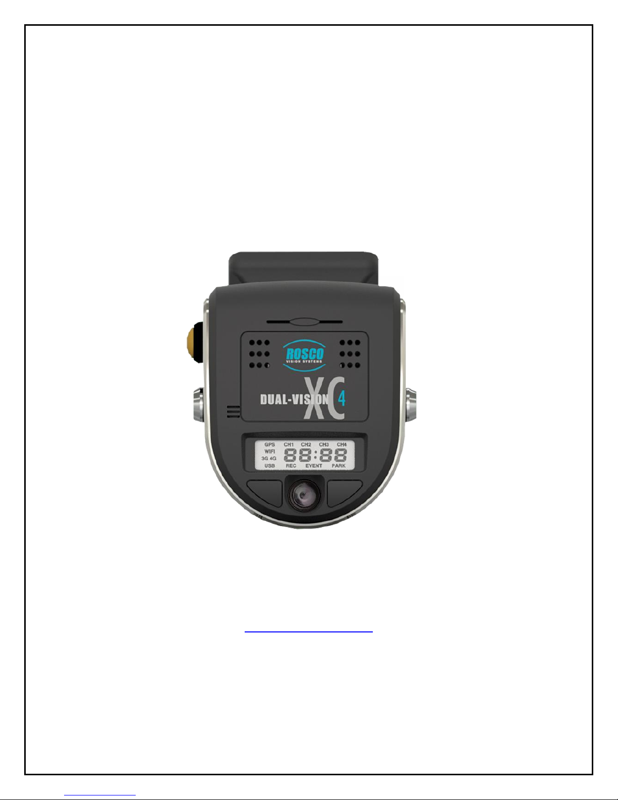
Dual-Vision™ XC4
Standard Version
Installation & Operating Instructions
19 DEC, 2017
90-21 144th Place, Jamaica, New York USA 11435
Phone: 800-227-2095
www.roscovision.com
Version 5.3
©2017 Rosco® Vision Systems, All Rights Reserved
Specifications and details are subject to change without prior notice.
Patent Pending
Page 2

2
TABLE OF CONTENTS
For the latest version of the User Manual please visit www.roscovision.com
Safety Instructions .................................................................................................. 4
Introduction ............................................................................................................. 5
Package Contents ................................................................................................... 6
Kit Part #: DV440 .......................................................................................................... 6
Features ................................................................................................................... 7
DVXC4 .......................................................................................................................... 7
DATA RETRIEVAL OPTIONS ........................................................................................... 7
DV-Pro5 Player (See page 18) ...................................................................................... 8
Recorder Detail ....................................................................................................... 9
Installation ............................................................................................................. 10
Power wiring diagram ................................................................................................ 10
PDC (Power/Data Control) Module Installation ......................................................... 11
Installing Mounting Bracket (DV402) ......................................................................... 12
Mounting the Recorder Unit (DV401) ........................................................................ 13
DVXC4 Operation .................................................................................................. 15
Drive Recording ......................................................................................................... 15
Continuous and Event Recording ............................................................................... 16
Recorder Removal & SD Card Retrieval .............................................................. 17
DV-Pro5 Player Program....................................................................................... 18
Introduction to DV-Pro5 (Standard Version) .............................................................. 18
Install DV-Pro5 ........................................................................................................... 19
DV-Pro5 Home Screen ............................................................................................... 20
Camera System Setup and Configuration ........................................................... 21
General Settings ......................................................................................................... 22
Channel Settings ........................................................................................................ 23
Event Settings ............................................................................................................ 24
Server Settings ........................................................................................................... 25
Remove SD Card from PC & Install into DVXC4 .......................................................... 26
Setting Up and Analyzing G-SENSOR Data .................................................................. 28
G-SENSOR Event Examples in DV-Pro5 ....................................................................... 29
Backing Up Video Files to Your PC (Import)................................................................ 30
Conversion of Video To AVI........................................................................................ 31
Vehicle Location Map ................................................................................................ 32
Format SD Card using DV-Pro5 .................................................................................. 33
SD Card Maintenance ........................................................................................... 34
DVCV4 Hardware Technical Specifications ........................................................ 35
Engineering Drawings ................................................................ .......................... 36
Application Notes .................................................................................................. 36
Page 3

3
Troubleshooting .................................................................................................... 37
AUX Cameras (Optional) ....................................................................................... 38
Spare Parts ............................................................................................................ 39
Commercial Warranty ........................................................................................... 40
Page 4
4
Safety Instructions
To ensure proper operation please read this User Manual
before installation and operation. Failure to follow this safety
notice may cause a malfunction and will void the warranty.
IMPORTANT
FOLLOW PROPER SHUTDOWN PROCEDURE
PRIOR TO UNLOCKING DVXC4 FOR SD CARD
REMOVAL.
(Refer to p. 17)
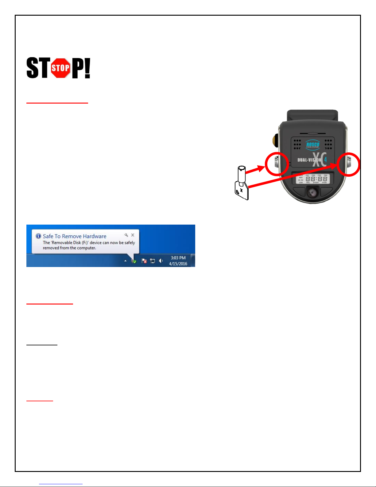
BEFORE REMOVING DVXC4 FROM
MOUNT, USE SUPPLIED KEYS TO
UNLOCK THE RECORDER. (Refer to p. 17)
ALWAYS USE THE “EJECT”
FEATURE ON YOUR PC PRIOR
TO REMOVING ANY SD CARD
FROM YOUR PC. FAILURE TO
DO SO WILL CORRUPT THE SD CARD. (Refer to p. 25)
CAUTION
THE FOLLOWING ACTIONS WILL VOID WARRANTY AND
MAY CAUSE AN ELECTRICAL SHORT CIRCUIT
DO NOT:
- Clean recorder with any liquids
- Insert foreign materials into the Dual-Vision XC4 device
- Attempt to disassemble, repair or modify the product
- Use cables, SD cards or fuses that are not provided by or recommended by Rosco®
NOTE
GPS The Dual-Vision XC4 Mounting Bracket must be mounted on the windshield in order to
have direct line-of-sight to the sky for reliable GPS satellite signal acquisition.
SD CARD The SD card must be reformatted periodically using the DV-Pro5 menu---Refer to
“SD Card Formatting” section on page 33.
Page 5
5
Introduction
Dual-Vision XC4 by Rosco provides HD recording of exterior/interior video, and continuously logs
vehicle travel data. Mounted on the windshield, Dual-Vision XC4’s twin cameras capture wide-angle
views of the forward exterior field of vision and the driver/passenger compartment. Privacy concerns
may be addressed through several means, including disabling of interior audio recording.
Data is recorded in a continuous loop, with oldest video erased by more recent video. The compact
system can hold many hours of data before any over-writing takes place. An internal GPS antenna
enables capture of vehicle location, speed, and direction. Important “Events” such as excessive GForce and speeding are placed in special protected files along with video segments identified by
the driver as being important.
All the data is stored in proprietary files located on a removable SD card. Video, audio, location
information, and G-force data may ONLY be reviewed by accessing the contents of the SD card
using Rosco’s proprietary DV-Pro5 Player software. The software is provided at no additional
cost to the end-user, and there are no follow-up fees for use or updating of the Player by
authorized users. Critical videos may be converted to standard media-player formats for
transmission to legal or administrative offices.
Security: Dual-Vision XC4 is a commercial grade product designed to be used in a variety of
applications. The Security Lock discourages unauthorized removal of the SD card. Installation via
hard-wire connection to a vehicle’s electrical system discourages tampering and provides
recording capability even after the engine has been shut off.
DV-Pro® Fleet Management Software: Dual-Vision XC4 kits are provided with the standard DVPro5 Player software. For more advanced needs, Rosco has developed DV-Pro5-ADS software, an
exclusive fleet management software program for managing multi-vehicle video recordings and
database management.
Contact Rosco Vision Systems or your authorized dealer for more information.
IMPORTANT
If you have a problem printing this document, please download and install the
latest version of Adobe Reader:
http://www.adobe.com/support/downloads/product.jsp?platform=windows&product=10
Page 6
6
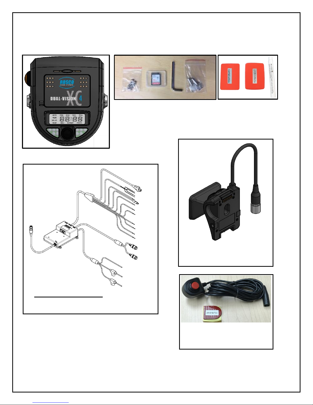
Package Contents
Kit Part #: DV440
Additional Items possibly included with your order:
• DV405: 4G Cellular Module
• DV406: Wi-Fi Module
• DV407: Wi-Fi Patch Antenna
• DV408: 4G Cellular Antenna
• DV412: Wi-Fi MIMO Screw Mount Antenna
• DV415: Wi-Fi MIMO Antenna Extension Cable (1 meter)
DV404: Advanced PDC:
Advanced version of Power and Data Control
Module
DV401: 2CH RECORDER UNIT
DV443: HARDWARE KIT incl., Temporary & Permanent VHB
Tapes with Primer Pen, Allen Wrench, Two Keys, Four Screws for PDC
mounting, 64GB SD card (DV453) – changed from 32GB to 64GB since
mfg. date code 1703
DV441: EXTERNAL DRIVER
EVENT BUTTON with CABLE
DV402: WINDSHIELD
MOUNTING BRACKET
Page 7
7
Features
DVXC4
• HD Quality Video Recording
• 720p Forward View Camera, 960H Interior Camera
• Optional Auxiliary Cameras
• High accuracy built-in GPS confirms location several times per second
• Built-in G-sensor accelerometer
• Locking mounting bracket protects SD card
• Tamper resistant
• Compatible with current and future high-capacity SD memory cards
• Extended hours of recording time per high capacity SD card
• Built-in infrared LED’s for excellent night interior view
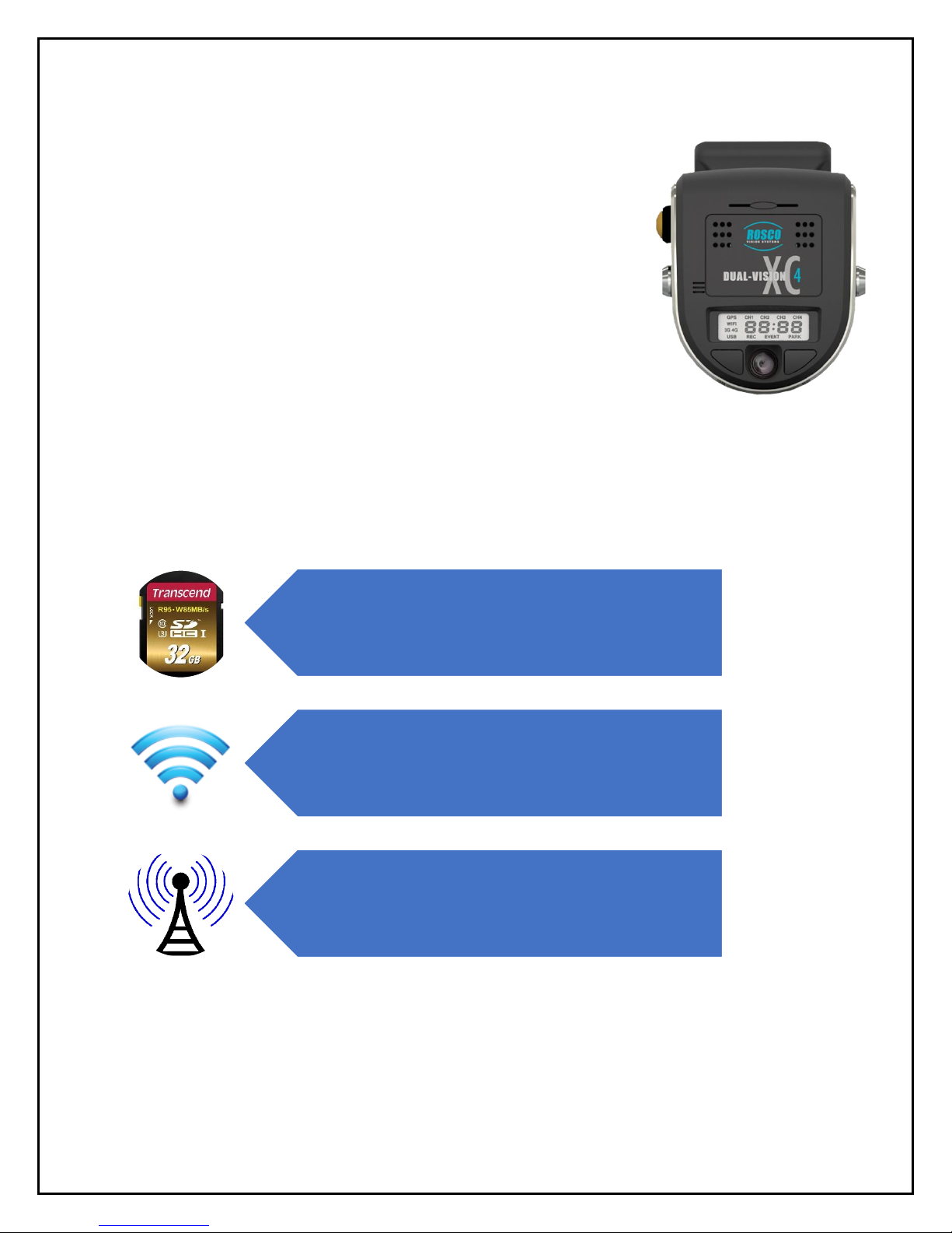
Manual SD card removal
Wi-Fi download to dedicated
fleet-owned server
Remote download and/or live
streaming video via cellular
transmission
DATA RETRIEVAL OPTIONS
Page 8
8
Video Playback and Data Management
Dual-Vision XC4 captures video/audio/GPS/sensor data and creates proprietary files,
which are only readable when viewed within Rosco DV-Pro5 program, included at no
additional charge with each recorder. DV-Pro5 is provided in one of two versions,
depending on the end-user’s data management scenario.
DV-Pro5 Player (See page 18)
• Proprietary video files
• Advanced playback control – frame speed & volume control, video zooming, full screen playback
• Quad-view playback windows
• Easy video management (organized on local storage media for easy retrieval)
• Historical GPS tracking with Google Street & Satellite Map Integration
• Graphical display of accelerometer values
• Built-in SD card formatting
• Platform for configuring per-vehicle Recorder settings
• Conversion of propriety files to .avi video files for sharing with authorized parties
Page 9
9
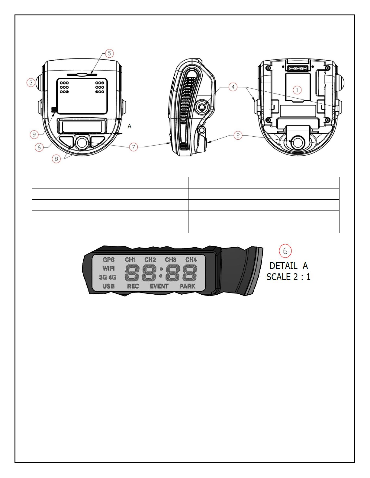
Recorder Detail
1. SD Card Slot (Authorized access only)
6. LCD Display
2. Front Camera (Exterior View)
7. Rear Camera (Interior View)
3. Driver Event Button
8. Infrared Illuminators
4. Windshield Mount Push Locks
9. Microphone
5. Audible Alarm Signal
Page 10
10
Installation
The complete installation requires a Recorder (equipped with cameras and microphone), a
Recorder Windshield Mount (equipped w power/video/data harness), and a PDC module. The
PDC (Power Data Distribution) Module is connected the vehicle’s power system. The PDC’s role is
to provide regulated power and external video/data connections to the Dual-Vision™ XC4
Recorder. See page 36 for a basic system connection diagram.
- Each vehicle has its own system and features. Please refer to your vehicle’s manual for
details.
- Turn the ignition key off while installing the cables and device.
- Select a secure protected location for the PDC module.
- Make sure to connect Ground wire first!
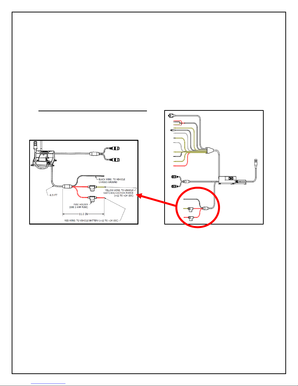
Power wiring diagram
IMPORTANT NOTE FOR INSTALLER
The DVXC4 Power Data Control Module (PDC) contains three wires—red, black, and yellow. The
yellow wire triggers Parking Surveillance by sensing the moment when the driver shuts the ignition.
Parking Surveillance typically provides recording at a lower frame rate for a pre-configured time
period. Parking Surveillance options are noted in the Configuration menu. In situations where a
manager chooses not to utilize this option, the system must be still wired properly to function. Use
the Configuration choices in DV-Pro5 to disable the Parking Surveillance Mode (see page 21).
Installers must be certain that the yellow wire is secured to the vehicle fuse block at a terminal which
will be at a zero-voltage state when the vehicle ignition key is OFF. A typical location on a fuse block
would be the ACC port for cigarette-lighter power. Please refer to the vehicle manual and fuse block
schematic to identify best locations for DVXC4 power/ignition/ground wire connection points. Zerovoltage state should be verified using a voltmeter prior to installation.
The PDC module includes internal circuit protection against high current or voltage spikes. It is very
important, however, for the professional installer to include appropriate external fuses.
Page 11
11
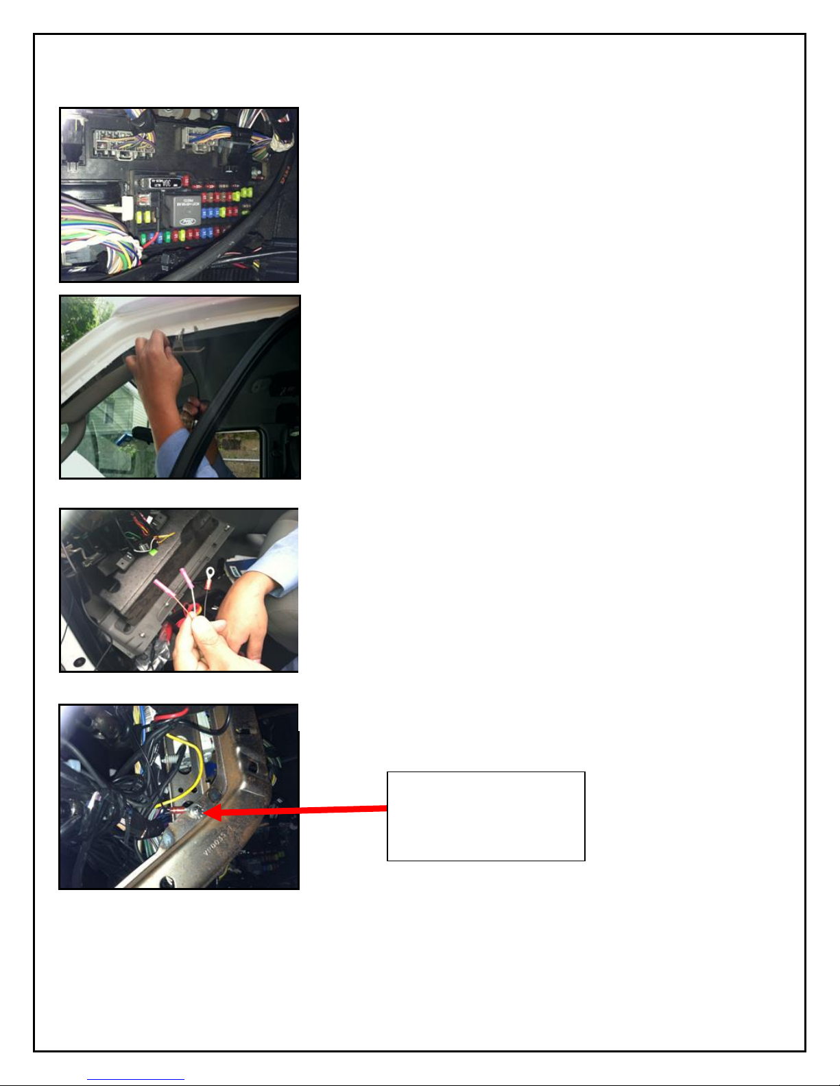
PDC (Power/Data Control) Module Installation
1. Unpack the DVXC4 box and prepare all the parts & tools
necessary for installation.
2. Find the location of the fuse box in the vehicle. Identify the
fuses for connection of the RED POWER wire and the
YELLOW IGNITION wire. Identify appropriate location for
installation of the PDC Module in the vehicle.
3. Identify approximate Dual-Vision™ XC4 Recorder location
on windshield. See page 12.Confirm sufficient cable length
available to connect PDC to the Dual-Vision™ XC4
Recorder. Remove the A-Pillar cover and insert the cable
at the gap between ceiling and windshield.
4. After determining that PDC location is appropriate, trim the
cable length as necessary, and make the following
connections:
a. Connect the BLACK WIRE (GROUND -) with ring
terminal to a chassis ground.
b. Connect the RED wire (POWER +) to a constant –
powered source which will remain live after the
ignition is turned OFF.
c. Connect the YELLOW wire (IGNITION) to an ACC
power source.
EXAMPLE:
Ground Wire Ring
Terminal connected to the
vehicle chassis ground
5. Find a location for the Driver Event Button that can be easily accessed by the driver.
Avoid locations where the button may be inadvertently pressed, such as by the driver’s
knee. Remove the adhesive film and attach the button. Connect the Driver Event Button
plug to the Data Cable Harness attached in the PDC Module. Secure all loose wires and
components with cable ties and reinstall vehicle panels.
Page 12
12
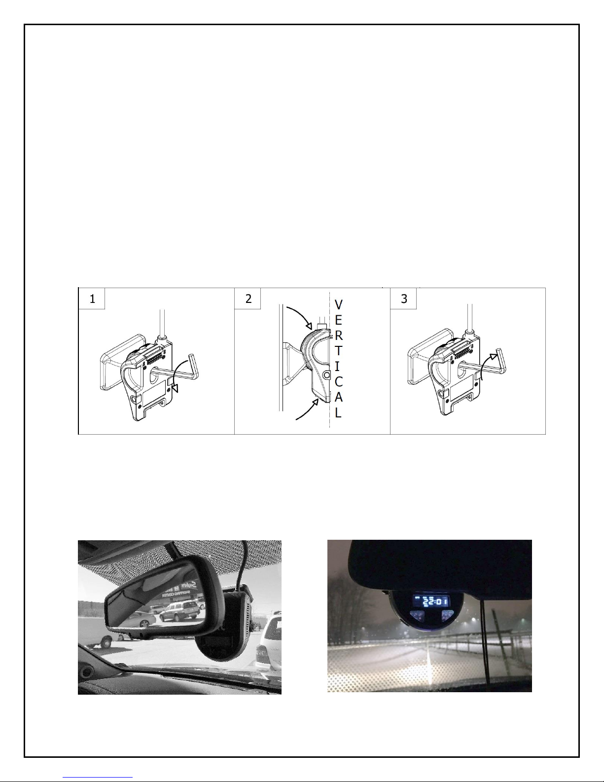
Installing Mounting Bracket (DV402)
1. IMPORTANT: Installation should only be done when ambient temperature is within 50°F-
100°F (10°C-38°C) to allow proper curing of mounting adhesive pads.
2. Determine the proper Dual-Vision™ XC4 Recorder location on windshield. Typically, the
Recorder is mounted behind and slightly below the mirror.
3. Make sure the interior-facing camera and the LCD display are not obstructed by the mirror.
Different vehicle/windshield combinations allow many other acceptable mounting locations.
The goal is always to minimize forward-viewing obstruction while enabling optimal recorded
images. Dual-Vision™ XC4 Recorder should be level both vertically and horizontally.
4. Clean the windshield glass with commercial glass cleaner. Using the adhesive pad marked
“temporary”, attach Mounting Bracket to windshield and press firmly.
5. After mounting, use the provided Hex Key to loosen the Hex Bolt on the Mounting Bracket.
Adjust Mounting Bracket to a fully vertical position and re-tighten the Hex Bolt.
6. Connect Recorder cable to the PDC Module. For most vehicles, this connection will be
made within the overhead space, and will be covered by the headliner. For additional
security, or for installations on very large windshields, it is advisable to enclose the
connection within a heat shrinkable tube or other protective cover, per your installer’s
suggestion.
Page 13

13
Mounting the Recorder Unit (DV401)
1. Install the SD Card as shown below. Hook the Recorder onto the top of the bracket and firmly
push the bottom of the Recorder to engage it into the Mount, confirmed by an audible “click”:
(See below)
Properly Assembled Recorder & Mount:
Interior View Left Side View Right Side View
2. Lock the recorder into position by pressing the two side-locks in, prior to turning on Power.
3. Turn the vehicle ignition on, and check that the Recorder LCD display lights up to confirm
proper electrical connection. Confirm that the LCD displays “GPS”, “CH1”, “CH2”, “REC” and
SD CARD
Page 14

14
time of day. “GPS” might not display if the vehicle is not outdoors. For the first time, it may take
up to 2 minutes for the Recorder to acquire a satellite signal and display “GPS”. (see below)
4. Allow Recorder to run for a few minutes. Turn the vehicle ignition off and confirm the LCD
display dims/blinks slowly, indicating Parking Surveillance Mode. Refer to p.17 to safely
remove the SD card.
5. Review SD card to confirm GPS acquisition and camera views. (See Pages 18-33 for Player
software installation and video playback instructions). Open DV-Pro5 on a PC, then insert the
SD card into the PC’s SD card slot or reader. At that time, the files on the test SD card will pop
up. Click to view test video. If the video recording indicates that Recorder location is not
acceptable, adjust the bracket angle and/or re-position bracket, and test again. If the Recorder
placement is acceptable, proceed to the next step for permanent installation.
6. Use a Nylon Pry Tool to carefully peel off the temporary adhesive pad and remove the
Mounting Bracket. Clean the windshield. Break open the glass primer ampoule and apply a
layer of 3M Primer on the surfaces of both the Windshield Mounting Bracket and the
windshield. Let the primer dry for at least two minutes. Attach the permanent adhesive pad to
the Windshield Mounting Bracket, and then carefully press the assembly onto the windshield,
holding it in place with pressure for about 30 seconds.
7. Do not re-mount Recorder yet. After permanently attaching the Mounting Bracket, allow at
least 2 hours at room temperature to make sure that the adhesive properly cures. Then make
sure there is an appropriate SD card inserted into the back of the Recorder, and proceed to
“clip-in” the Recorder body into the Mounting Bracket. You are now ready to begin recording.
IMPORTANT
Installation of permanent mounting should only be done when windshield is at room
temperature. Allow 2-4 hours for adhesive bond to cure properly before operating vehicle.
Page 15

15
DVXC4 Operation
Drive Recording
• Your DVXC4 is supplied with an SD card pre-configured with factory default settings (see
page 22-25). Insert the SD card into a PC and add identifying information. Of course, you
may also change the values of any configurable setting as desired. Make sure to “SAVE” as
instructed on page 25.
• After re-inserting the SD card into the back of the Recorder, proceed to “click-in” the
Recorder into the Mounting Bracket as previously described.
• Turn the ignition on. “boot” will appear on the LCD display indicating that the Recorder is
initializing. Approximately 30 seconds after powering on, the LCD will briefly display “F1XX”
indicating the firmware version, and a chime will sound indicating that initialization is
complete. Although GPS still may not be active, recording begins when “REC” is displayed.
• Within two minutes of start (assuming outdoor location), the GPS signal will be acquired, and
the GPS icon will light up. Subsequent vehicle starts will acquire GPS signal significantly
faster than the original start-up. GPS location data will be continuously analyzed, and each
video file will contain embedded location, speed and direction data.
NOTE: When the vehicle is in motion, the LCD displays vehicle speed. When the vehicle comes
to a complete stop, the LCD speed indicator will display the time after a few seconds. The
option to show speed can be disabled by changing the SD card configuration (See Page 22)
Page 16

16
Continuous and Event Recording
Continuous (Normal) Recording
• When the ignition is OFF, Dual-Vision™ XC4 Recorder remains powered for an additional 5
seconds to finish recording. If Parking Surveillance is ON, LCD Display will show “PARK” icon
on and count-down the parking time in minutes and the LCD will be blinking and dimming
slowly and the recording will be continued until the parking time ends.
• Dual-Vision™ XC4 creates proprietary files (identified as “.nvr” files) which contain video, audio,
and tracking data. Proprietary .nvr files will only playback on DV-Pro5 Player program.
• Continuously recorded .nvr files are NOT protected against overwriting. When the capacity of the
SD Card has been reached, the oldest non-Event files are overwritten.
Event Recording
• Event Recording – When a preconfigured speed or G-sensor values are exceeded, or when
Driver Event Button is pressed, an “EVENT” is created. That is, the .nvr file associated with that
Event is marked and protected against overwriting.
• Event files may be locked or unlocked via the SD Card configuration (See Page 24).
o If Event Locking is enabled, new event files will be created until they fill up about 25%
of the SD card space. Those first event files will never be overwritten and the DVXC4
LCD will display “FULL”. However, the remaining 75% of the card will continue to
record normal continuous video and overwrite as needed. New event files will be
treated as normal continuous video files and will be overwritten by normal continuous
files. In order to remove the locked files, the card will need to be formatted (See page
33).
o By default, Event Locking is disabled in the SD card configuration. New event files
will be created until they fill up about 25% of the SD card space. The newest event files
will then overwrite the oldest files (a FIFO queue, first-in first-out). It is strongly
recommended that event locking is left disabled in order to preserve the newest
event files for the maximum amount of time without user intervention.
Speeding Events
G-Sensor Events
Driver Button Events
Parking Mode Denoted
Normal Continuous Video
Page 17

17
Recorder Removal & SD Card Retrieval
IMPORTANT: FOLLOW PROPER SHUTDOWN PROCEDURE.
RECORDER MUST BE COMPLETELY POWERED OFF
BEFORE DETACHING RECORDER OR REMOVING SD CARD.
ALWAYS power off the vehicle prior to removal of SD Card from Dual-Vision™ XC4 Recorder.
• If parking surveillance mode is OFF, turn ignition off. It is safe to remove the SD card after
the Recorder’s LCD display turns off.
• If parking surveillance mode is ON, turn ignition off and wait for few seconds until the
LCD display begins blinking/dimming. Then press and hold the Driver Event Button for at
least 5 seconds until the LCD indicates “SHUt”, and then goes dark. It is now safe to
remove the recorder and SD card as shown below.
BEFORE REMOVING RECORDER FROM MOUNT, USE THE
SUPPLIED KEYS TO UNLOCK THE RECORDER (STEP 1
BELOW).
SD CARD
Press down
and release
SD Card
Grab bottom of
recorder and pull
back as shown.
Page 18

18
DV-Pro5 Player Program
Introduction to DV-Pro5 (Standard Version)
Note: This manual will only cover the Standard version of DV-Pro5. See the
separate “DV-Pro5 Advanced User Manual” in order to use DV-Pro5 with
advanced wireless features such as WIFI/ADS and cellular 4G LTE
streaming/cloud services.
Use the Standard version of DV-Pro5 to play video files off the DVXC4 SD Card.
The player can simultaneously show 4 channels of video, display a live map, and
show speed, G-sensor data, etc. The player can also be used to format SD cards,
setup user preferences for recording (SD Card Configuration), back-up SD card
files to a computer (Import), or export video to .avi files.
NOTE: DV-Pro5 is compatible with most PC operating systems (Windows 7, 8 and
10). It is currently not compatible with Mac OS-X or Unix-based operating systems.
Page 19

19
Install DV-Pro5
Your SD card comes pre-loaded with the files required to install DV-Pro5 on your PC. If those files
are not available, please contact Rosco Vision Systems and we will send you the required files.
To install “DV-Pro5” from the SD card, insert the card into PC and click “open folder to view files”.
Then click “DV-Pro-Setup-Basic-5.0.0.xxx.exe” (xxx denotes the latest version) to begin the
installation.
If the below “User Account Control” window opens, click “Yes”. Click “Next” on the subsequent
windows to complete the installation. By default, the program will install to C:\Program Files
(x86)\DV-Pro5, but this can be changed if desired.
Page 20

20
DV-Pro5 Home Screen
NAME
DESCRIPTION
A
Forward Camera
Channel 1: Displays exterior video recorded through the windshield
B
Interior Camera
Channel 2: Displays interior video, typically driver and passengers
C
AUX Camera 1
Channel 3: External camera video, typically a side or backup camera (Optional)
D
AUX Camera 2
Channel 4: External camera video, typically a side or backup camera (Optional)
E
Metadata
Displays video file info including, name, time, vehicle ID, driver and speed etc.
F
G-Force graph
3-axis graphic displays vehicle motion and any impacts detected by the G-Sensor
G
Playback Time
Counting video playback time
H
Calendar
Click this icon to open a calendar view of all recorded video. The days with recorded video will be
circled. Double click a day to list that day’s (up to 24 hours) video files. You may also click the arrows
on either side of the date to move forward/backward one day.
I
File List
Displays up to one day (24 hours) of video files in 1-minute segments directly from the SD card or
another location on the computer. Double click on a file to play it. If no video files are shown, click the
“Change” button above the file list to choose the SD Card directory.
J
Playback Menu
Bar
Use to review video. The following controls are available: Playback speed, skip to previous/next video,
step one frame back/forward, rewind/fast forward, pause/play, full screen/window view, zoom, audio
level, brightness and contrast.
K
Map
Shows the vehicle location on a map
L
File Menu Tree
Load SD: Click to load video files from the SD card into the file list
Load Local: Click to load videos from a local directory of the PC/Network Drive/etc.
DV-Pro5 will automatically choose the directory where SD files were last saved to
(see “Import” below).
Import: Click to save video files to a local PC directory/network drive etc
SD Config: Click to review or configure recording preferences
Format SD: Click to format the SD card
Export AVI: Click to Export and save video as an .AVI file
Show Route: Select multiple files and click this button to show the vehicle’s route on
the map
A
C
K
B
D
E
G
H
F
L
I
Page 21

21
Camera System Setup and Configuration
Introduction: Use the DV-Pro5 program to configure all recording settings on the Dual-Vision XC4 Recorder.
The program will write a configuration to the SD card, and the DVXC4 recorder will automatically use the
configuration from the SD card when the vehicle is powered on.
Insert the SD card into the PC and open DV-Pro5. You may click on the shortcut icon for “DV-Pro5” on
your Desktop PC screen. Click on the System Setup configuration button (
). The below window
will then appear and you can change the recording and event flagging options as needed. 4 pages of
settings are available: General Settings, Channel Settings, Event Settings, and Server Settings.
Locate SD Card in DV-Pro (If not automatically loaded): On any page of the settings, click the “Source”
button in the bottom and go to “Removable Disk” where the SD card is located and highlight “config.txt” file
and click “Open”. Then the current configuration settings in the SD card will automatically populate in the
configuration pages.
Save: Review and change settings in the configuration menus as needed and click “Save”. The new
configuration will be saved in the SD card. Insert the SD card into the Recorder, mount the recorder on the
bracket and power on the vehicle. The Recorder will automatically use the new configuration for recording
video, registering events, etc.
Save As: Click to back up the SD config.txt file to a PC directory. Navigate to the desired directory, and
type a filename (example: “config_backup.txt”). Click Save.
Search Source of config.txt file
Page 22

22
General Settings
CONFIGURATION ITEM
DESCRIPTION
ID Settings:
Enter a vehicle number or nickname, and Driver name. These names will appear in the video
file list in DV-Pro5 and will be automatically used to name video folders when importing video
to your PC (see page 30).
System Settings:
LCD Backlight Day/Night Mode: This adjusts the brightness of the numerical LCD display on
the actual DVXC4 recorder unit. Set a brightness for day and night. The DVXC4 will
automatically detect daytime and night time/dark conditions and adjust the display brightness
automatically.
If “Display speed on LCD” is checked, the recorder display will show the speed of the vehicle
while moving and display time when stopped. If this is unchecked, the recorder will constantly
display time instead.
General Settings:
Time Zone: Choose the correct time zone according to where the vehicle is predominantly
operated. The recorder will automatically increment/decrease an hour according to Daylight
Savings Time.
Parking Surveillance Mode Timer: Check the box to enable the DVXC4 to record
surveillance video while the vehicle is parked and powered off. If this box is unchecked, then
the DVXC4 will turn off when the vehicle ignition is turned off.
Parking Duration: Adjust the duration of Parking Surveillance mode. This value can be set up
to 24 hours (0-1440 min).
File Download Duration: (For DV-Pro5 Advanced Version ONLY) This is the time allotted
for WIFI download of video from the recorder after the vehicle ignition has been turned off. This
setting is independent of the parking surveillance timer above.
Time Zone Setting
LCD Backlight Setting
Enable/Diable Speed on LCD
Page 23

23
Channel Settings
Prior to recording video for the first time, ensure the Channel Settings are configured on the SD
card so that the proper frame rate and video quality is set. The below screen shot contains the
factory default settings. Note 1: Changing FPS and Quality Settings on each channel will impact
the video file size. The lower numbers in these settings will result in lower file size, thus yielding
more hours of driving video on the SD card. Note 2: Channel 3 and 4 (AUX cameras) are disabled
by default. If they are enabled and no cameras/video feeds are connected, the recorder will show
“ERR 5” upon startup.
CONFIGURATION ITEM
DESCRIPTION
Enable
Check to enable or un-check to disable video recording on that channel.
Main FPS – Frames/Second
Frame rate while the vehicle is powered on. 7 FPS is satisfactory for most applications
Main Quality
Video quality while the vehicle is powered on. 1-Normal is satisfactory for most
applications
*Parking FPS – Frames/Second
Frame rate while the vehicle is powered off and the recorder is in parking surveillance
mode. 1 or 2 FPS is satisfactory for most applications.
Parking Quality
Quality while the vehicle is powered off and the recorder is in parking surveillance
mode. 1-normal is satisfactory for most applications.
**Audio Volume
Adjust audio volume levels from OFF to 4(Max) on Ch2, Ch3, Ch4. Level 3 is
satisfactory for most applications. Ch3, Ch4 audio default is OFF.
Enable Sub stream
Check to enable or un-check to disable streaming video over the 4G cellular network.
*NOTE: *Parking Surveillance: settings are independent from the values selected for normal driving mode
Configuration. **Audio Volume: Ch1 has no audio. The recorder uses Ch2 to record audio. To hear audio in DV-Pro,
the Channel 2 video window must be clicked/highlighted, click volume icon in the playback control bar and adjust
desired volume.
Channel 1: Camera
Facing Forward Traffic
Channel 2: Camera
Facing Inside of vehicle
Channel 3&4: Auxiliary
Cameras Connected to
PDC. (Disabled by
Default)
Page 24

24
Event Settings
This page configures the way videos are flagged as events. All videos flagged as events are
saved to a separate portion of the SD card. This way, they are generally preserved much longer
than regular video files (up to a year depending on how often they are generated). Care must be
taken to adjust these settings for optimal incident or driver behavior reporting.
CONFIGURATION ITEM
DESCRIPTION
Event Settings:
Driver Event Button: enable/disable the driver event button located on the recorder itself. The driver hits
this button to manually flag an event.
External Driver Event Button: enable/disable the button. Same as the above driver event button except
connected via a cable.
Speed Event: enable/disable events automatically triggered by the speed of the vehicle
Speed Threshold: Set the speed at which the speed events are automatically triggered.
Trigger Output: Choose an output in order to send a 12V signal to either the Out 1 or Out 2 white wires
coming from the advanced PDC module whenever that particular event occurs (see page 36). These
outputs are set to off by default.
G-Sensor:
The DVXC4 contains a G-sensor to sense vehicle motion (stopping, acceleration, etc). Adjust these
settings for optimal event flagging based on motion/impacts etc.
Axis Enabled: Enable whether that axis is used at all. X= Left/Right Y= Front/Back Z= Up/Down
1= the force due to gravity, so the Z axis should always be set greater than 1. 0= no force at all.
Basic & Critical: These G-sensor events are triggered while the vehicle is powered and moving. Critical
values should be set higher than basic to denote more intense accelerations.
Parking: G-sensor events while the vehicle is off and the recorder is in parking surveillance mode. Set
these values lower in order to sense disturbances to the vehicle while it’s parked.
Sensor Settings:
Sensor Inputs 1-4 correspond to the 4 yellow wires on the advanced PDC (see page 7). These wires will
sense 12V inputs to trigger Events. Input examples are a seat belt confirmation, a door open switch, etc.
Others:
We strongly recommend leaving the “Lock Event Files” selection unchecked. This is to allow the newest
event files to replace the oldest event files in the case that the event file portion of the SD card is full.
Page 25

25
Server Settings
This page is for configuring wireless video file download and streaming from the DVXC4 recorder
to a server or cloud. For basic DVXC4 installation with SD-Card video file transfer only, leave all
options on this page unchecked (see below screenshot). For advanced DVXC4 installation with
WIFI or 4G streaming, see separate “Advanced DV-Pro5 User Manual”. After changing/reviewing
the configuration settings as desired, click “Save” and exit the configuration menu.
Page 26

26
Remove SD Card from PC & Install into
DVXC4
Upon completion of any of the following:
• Reviewing/managing video files
• Updating DVXC4 configuration
• Adding “upgrade” folder to SD card
• Reformatting SD card
Exit DV-Pro5, and follow proper SD card ejection
procedure. Before removing the SD Card from your
PC, open a Windows Explorer window, right click on
the SD Card (usually labeled “Removable Disk”) and
click “Eject”. Wait for Windows to confirm by
showing a “Safe to Remove Hardware” balloon, and
then remove the SD card.
You may now insert the SD Card into the
DVXC4 recorder unit as shown on Page 13.
You are now ready to turn on the vehicle and
begin recording video.
Page 27

27
Video Playback Instructions
1. To playback video, turn off the vehicle and remove the SD card from the DVXC4
recorder unit according to the instructions on Page 17. Insert the SD card into your PC
and open DV-Pro 5.
2. Select a video file from the file list. If no video files appear in the list, click the “change” button
to choose a different video file source.
3. Select the location (hard drive, external storage, or SD card) where the recorded data is stored
and choose folder with “date” such as “2015-11” then click “Select Folder” to open video files.
4. When the video files are listed on DV-Pro player screen, Select and double click a video file in
the list to play video.
EVENT TYPE
DESCRIPTION
SPEED Event (S)
Indicates when the vehicle exceeds pre-configured speed limit. Shown as a
yellow check mark in the file list and as a yellow bar on the video progress bar.
BUTTON Event (D)
Indicates activation of Driver Event Button. Shown as a green check mark in the
file list and as a green bar on the video progress bar.
G-SENSOR Event (G)
Indicates when vehicle experienced sudden acceleration, deceleration or rapid
side-to-side movement. Shown as a red check mark in the file list and as a red
bar on the video progress bar.
PARKING Mode (P)
Indicates which videos are recorded during Parking Surveillance Mode. Shown
as a white check mark in the file list.
File name
of video
Date and time
when the video
was recorded
Displays the type
of recorded
Events
(G-Sensor, Driver
Button, Speed)
Point and
duration
of an
Event
Point of
video
playback
Location of
vehicle (Avail.
when PC
connected to
Internet)
Change
video file
source
Page 28

28
*NOTE: Click menu bar to sort by file name, record time or event type
Setting Up and Analyzing G-SENSOR Data
The G-Force sensor detects changes in directional forces affecting the vehicle. The Dual-Vision
XC4 Player displays G-force data in a graphical format, and creates Events when those forces
exceed supervisor-set values. One may interpret the data as follows:
Notes on G-Force Sensor Settings
Note that X & Y axes are 0 when vehicle is stationary. The Z-Axis is at +1 when vehicle is
stationary and on a flat slope, due to the force of gravity. Adjust the g-sensor threshold values in
the DVXC4 configuration with this in mind (see page 24). This is a trial-and-error effort,
since different types of vehicles will react differently under various road conditions. The values
for the Z-Axis must be set above 1, so that it does not record Events while the vehicle is not
moving. Under normal driving conditions for an automobile, settings of X= 0.5 G, Y= 0.5G,
Z = 1.8 G are recommended as being sufficient to identify driver-behavior issues while being high
enough to avoid most unnecessary event-marking caused by potholes or normal braking.
VEHICLE STOPPED
DECELERATION
FRONTAL COLLISION
RIGHT/LEFT TURN
KEY
Z-AXIS : UP / DOWN MOTION
X-AXIS : LEFT / RIGHT MOTION
Y-AXIS : FRONT / BACK MOTION
E X A M
P L E S O N L Y
ACCELERATION
LEFT SIDE COLLISION
Page 29

29
G-SENSOR Event Examples in DV-Pro5
Hard Braking
Hard Turning
Page 30

30
Backing Up Video Files to Your PC (Import)
DV-Pro has a built in “Import” function that creates and automatically organizes a database of
video on your local machine/server, limited only by the data storage resources at your disposal.
Step 1: Insert SD card into Reader slot or Device and open DV-Pro 5. Video file list will populate. You
can choose to import the complete contents of the SD card to the PC or just to import files by Event type,
date/time, or by individually selecting files of interest.
Step 2: Click on the Import icon (
) located at the lower right corner of the player screen next to the
map. A pop-up “Import” window will then appear. NOTE: If “Source” is blank, click “Change Source” to
select the directory of the SD card. Make selections as needed. Click “Import Files” to save the files to the
PC.
Step 3: The window will show save progress. Do not close the window until all selected files imported.
Step 4: When the window confirms “Importing Complete”, click “Close” or click “View Files” button to
confirm the files were saved correctly.
Step 5: Confirm the desired files were saved to the directory chosen in Step 2.
Note: Prior to clicking “Import”, the “cog”
icon on the home screen can also be
clicked to change the import location.
Page 31

31
Conversion of Video To AVI
This function converts a portion of the recorded data into an .AVI file that can be viewed on
universal video players such as Windows Media Player, VLC Player, etc. This feature allows
sharing of video across multiple platforms via email or any other means of file transfer.
1. In the main player Window, choose the video
file(s) of interest using the Select Checkbox.
Click the Export AVI button ( ),
click “Change” button to select the target
directory, and make the desired selections of
channels and audio (see right).
Note: DV-Pro5 cannot immediately save
the .avi files to external media such as an SD
Card or USB memory stick, but only to your
PC’s hard drive. The AVI file can however be
moved to any external media after initial
export. Click on Start and conversion will take
place.
2. The converter will create AVI files and will
place them in the desired PC directory.
The window will show the progress of file
conversion and confirm with a “Conversion
Complete” message when done. Click
Close, or “View Files” to confirm correct
export.
3. If viewing files, click on the
AVI file to playback video
using a universal player
program such as Windows
Media Player or VLC
Player.
4. You may now move the
new .AVI files to any SD
card or other external
media. You may also
email them as
attachments, upload via
Dropbox or other FTP
service, etc.
Page 32

32
Vehicle Location Map
The Dual-Vision™ XC4 records GPS data to enable historical review of vehicle location and route.
The map coordinates are automatically synchronized with Google Maps®. You may manually resync the map by clicking the “Popout” button on the upper right corner of map.
Additionally, one may select various video files using the check boxes, and then click the “Show Route”
button in the File Menu Tree. A map window will then appear showing the vehicle’s traversed route in
the span of the selected videos, highlighted with a red line.
NOTE: To use any of these functions, the PC must have an internet
connection.
Page 33

33
Format SD Card using DV-Pro5
IMPORTANT
SD CARD FORMATTING MUST BE DONE USING DV-PRO5
ONLY. USING THE PC’s DEFAULT FORMATTER OR A THIRD
PARTY TOOL WILL RENDER THE SD CARD
UNUSABLE BY THE DVXC4 RECORDER.
1. Open DV-Pro 5. Select the SD CARD using the “Change” button on the
main screen. (NOTE: The SD Card will be automatically recognized if SD
Card is inserted before opening DV-Pro5.)
2. Click the “Format SD” menu button in the bottom right corner of the main
screen.
3. If you want to keep the current configuration, check the box to save it in the formatted SD
card. Otherwise, the contents of the SD card will be completely erased. Click the “Format”
button to format the SD card.
4. When the format is complete, the following screen will appear:
5. If the “Keep configuration” box was checked
prior to format, go to “Computer/Removable
Disk” and confirm “config.txt” file is still there.
You may use the newly formatted card in a
Recorder as-is, or use DV-PRO5 to update
the configuration if needed.
Close DV-Pro 5. USE THE “EJECT” FEATURE ON YOUR PC PRIOR TO REMOVING
THE SD CARD FROM YOUR PC. See page 26. Then see page 14 to re-insert the SD
Card into the Dual-Vision™ XC4 Recorder and into the vehicle.
Page 34

34
SD Card Maintenance
IMPORTANT
Remember to ALWAYS turn OFF the vehicle prior to removal of SD Card from
Dual-Vision™ XC4 Recorder.
• When parking surveillance mode is OFF, turn ignition off. It is safe to remove the SD card
after the Recorder’s LCD display turns off.
• If parking surveillance mode is ON, turn ignition off and wait for few seconds until the
LCD display begins blinking/dimming. Then press and hold the Drive Event Button for at
least 5 seconds. The LCD will show the message “SHUT” and then turn off after a few
seconds. FOLLOW DIRECTIONS ON PAGE 17 TO UNLOCK THE RECORDER AND
REMOVE THE SD CARD.
Do Not Use SD Card for any other purpose other than recording with the DVXC4. Using this SD Card for
any other purpose or removing the card while the Recorder is powered may cause a fatal error on the SD
Card. You will lose important data if SD card is removed without following proper shutdown procedures.
Recommended: Use the DV-Pro 5 “Import” function to back-up the SD Card’s video files onto your
PC or other mass storage resources.
IMPORTANT: Rosco recommends formatting the SD Card once every six months to a year, using the DV-
Pro5 program, to prevent SD Card errors from accumulating over a long period of time. Periodically
formatting SD card using DV-Pro 5 program not cleans up bad sectors in memory and will decrease the
possibility of losing or corrupting video files.
Note that upon formatting the SD Card, all existing files will be deleted. Be sure to perform a backup of
any important video files and configuration prior to reformatting. After formatting, you may insert the SD
card into Dual-Vision™ XC4. The Recorder will automatically write the previously used recording
Configuration file to the SD card.
The “DV-Pro5” program and User Manual does not automatically re-install onto the SD Card. If desired, it
may be added manually by copying and pasting from another location. New data files will be automatically
created as driving resumes.
Consult Rosco or an Authorized Reseller for SD Card compatibility. Not all SD Cards work with the DualVision XC4 Recorder. The following is a list of approved SD Cards which may be purchased from Rosco.
This list may be periodically updated without notice.
SD CARD SIZE
ROSCO PART #
DESCRIPTION
32GB
DV452
SDHC CARD, 32GB, CLASS 10, PRELOADED W/ MANUAL
& DEFAULT CONFIGURATION FILE
64GB
DV453
SDXC CARD, 64GB, CLASS 10, PRELOADED W/ MANUAL
& DEFAULT CONFIGURATION FILE
128GB
DV454
SDXC CARD, 128GB, CLASS 10, PRELOADED W/ MANUAL
& DEFAULT CONFIGURATION FILE
256GB
DV455
SDXC CARD, 256GB, CLASS 10, PRELOADED W/ MANUAL
& DEFAULT CONFIGURATION FILE
IMPORTANT: SD Card Reader (USB 3.0) – The above High Capacity SD cards requires using USB3.0
Compatible SD Card Reader for a faster read/write performance, stability and reliability of reviewing video
on DV-Pro5 player software.
Page 35

35
DVCV4 Hardware Technical Specifications
PRODUCT SPECIFICATIONS
Built-in Cameras
Two Cameras with CMOS Sensors
Camera Viewing Angles
Front Camera: D135°x H85⁰ x V55⁰
Interior Camera: D160° x H112⁰ x V80⁰
Video Compression
H.264 with CBR (Constant Bit Rate)
Technologies used for
Enhanced Video Quality
WDR (Wide Dynamic Range), Active antiblooming and dark sun cancellation, Lens
shading and pixel defect correction, Color
interpolation & correction, Luminance and
color noise reduction, Edge enhancement,
Gamma correction, Motion detection, white
balance to balance color fidelity & contrast
Resolution
720p for windshield view and 960h for
cabin interior view camera
Audio
1CH, Mono in the Interior View Camera
Support Ch3, Ch4 cams for audio
GPS
Built-in GPS module w/antenna
G-Sensor (X, Y, and Z)
Built-in 3D Acceleration G-Sensor
Volume
Configurable (Off – 5)
Video Quality for Recording
Configurable (1-normal to 5-high)
Video Frame Rate
Configurable (1–30 frames/sec/camera)
Memory Card
32GB SDHC up to 256GB SDXC
Operating Voltage
12 VDC ~ 24 VDC
Operating Temperature
-20⁰C ~ +65⁰C (-4⁰F ~ +149⁰F)
Storage Temperature
-40⁰C ~ +85⁰C (-40⁰F ~ +185⁰F)
Size
W 3.70” x L 4.13” x T 2.0”
Weight
7.5 oz. recorder unit, 5.3 oz. bracket,
12.6 oz. recorder unit with bracket
Current Consumption
@12.8 VDC
Maximum
~1.2 A (4 channels with Wi-Fi and 4G
Wireless)
Operation
~450mA (2ch only) ~650mA (4ch)
Parking
~400mA (2ch only)
With Wi-Fi
~550mA (2ch only), ~700mA (4ch)
PDC only
~200mA (without Recorder)
OFF/Standby
~10mA
Standard Compliance
FCC
Certified Part 15 Subpart B
EMC
ANSI C63.4-2009
CE
Pending Approval
Page 36

36
Engineering Drawings
Application Notes
• AN_DV440_STSS1000_STSC109R_STSC141.pdf
• AN_DV440_STSK4530_STSC118.pdf
• AN_DV440_STSM251_STSS1000.pdf
• AN_DV440_STSK7965_STSH390_STSS1000.pdf
• AN_DV440_STSK7965_STSW1001.pdf
• AN_DV440_STSM205_STSW1001.pdf
The above Application Notes are available for resellers & installers upon request. Call Rosco
Customer Support or send email to techsupport@roscovision.com for more detail.
Page 37

37
Troubleshooting
Problem
Possible Cause
Corrective Action
Power
LCD display is dark.
No chime heard upon
starting vehicle.
No power
to Recorder
Check the power cable connection
and fuses
LCD
Display
LCD display is faint, but
chime heard upon
starting vehicle.
Low brightness
setting
Open Configuration screen in DV-
Pro5 and adjust Backlight
Day/Night Settings
Event
Event icon is
constantly lit.
Constant Events and
chimes due to bumps
and potholes
Increase G-Sensor settings
based on your vehicle types and
needs.
Speed
Constant chiming
Speed Event
Threshold set too low
Increase Speed limit threshold
based on your vehicle needs.
GPS
GPS icon remains unlit
while driving, vehicle
speed not indicated on
LCD display
GPS antenna is not
able to acquire
satellite signal
Relocate Recorder and
mounting base to position with
line-of-sight to sky
LCD
Message
ErrX
Error notices on
display
Contact your dealer or Rosco for
Assistance
LCD
Message
SD_E
SD Card error
No SD Card, SD
Card not
reading/writing
Remove and properly insert
SD card OR
Reformat or replace
SD Card
Playback
Blurry video
Camera/lens
problem
OR
Low Video Quality
Setting
Make sure Camera/lens is clean
and clear of obstructions
AND/OR
Increase video quality in DV-Pro
Configuration
Playback
Low/Choppy Video
Framerate
Low Frame Rate
Setting
Increase frame rate in DV-Pro
Configuration
Playback
No audio
Improper software
settings in Player or
Configuration screens
Configuration - Ch1 has no
audio but you can set Audio
Volume level for each Ch2, Ch3,
Ch4 cameras thru DV-Pro5
configuration menu
DV-Pro5 Player – adjust
Volume Control slider as
desired.
Check speaker settings on PC
Speaker
No chime or
loud chime
Improper setting in
DV-Pro5
Configuration Menu
Adjust the
Speaker Volume setting in the
DV-Pro5 configuration menu.
Page 38

38
AUX Cameras (Optional)
The Dual-Vision™ XC4 is capable of recording video from two extra auxiliary 4-pin (“AUX”)
cameras which may be connected to the External Camera ports in the PDC module. Rosco has a
full range of cameras available for selection including both rugged and compact, license plate
cameras, integrated brake light, side view, bumper/flush mounted, rear hatch, and interior dome
surveillance cameras.
Contact Rosco or an authorized dealer for a list of compatible 4-pin cameras. The following highdefinition (960H) cameras are recommended:
Part
Number
Description
STSC167
Side View Camera, Right Front/Left Rear, Silver, W/ Night Vision, 960H
STSC168
Side View Camera, Left Front/Right Rear, Silver, W/ Night Vision, 960H
STSA1006
5 degree adaptor, silver, for STSC167, STSC168
STSC169
Internal Dome Camera, Black, W/ Night Vision & Audio , 960H, 0° and 25°
Mounts Included
STSA1007
0 degree adaptor, black, for STSC169
STSA1009
25 degree adaptor, black, for STSC169
STSC170
Internal Dome Camera, White, W/ Night Vision & Audio , 960H, 0° and 25°
Mounts Included
STSA1010
0 degree adaptor, white, for STSC170
STSA1011
25 degree adaptor, white, for STSC170
STSC141
Backup Camera, Silver, W/ Night Vision & Audio
Page 39

39
Spare Parts
Rosco Sales
Part Number
Description
DV440 KIT (Included)
DV401
Dual-Vision™ XC4 2Ch Recorder Unit Only
DV402
Dual-Vision™ XC4 Windshield Mount Bracket Only
DV404
Dual-Vision™ XC4 PDC Only
DV441
Dual-Vision™ XC4 External Driver Event Button
DV442
Dual-Vision™ XC4 Adhesive Pads plus Primer
DV443
Dual-Vision™ XC4 Hardware KIT for DV420 or DV440
DV453
SDXC Card, 64GB, CL10, PRELOADED
MODEMS (Optional)
DV405
4G LTE Cellular Modem, w/SIM for US
SIM1002
Verizon SIM card for DV405
DV418
4G LTE Cellular Modem, LT1002 w/SIM for US
DV422
4G LTE Cellular Modem, EM1000T-NA wo/SIM for Canada
DV406
USB Wi-Fi Modem w/PDC mount Cover & Hardware
ANTENNAS (Optional)
DV408
4G LTE Cellular Windshield Mount Antenna for DV405, DV418, DV422
DV407
Wi-Fi MIMO Windshield Mount Antenna for DV406
DV412
Wi-Fi MIMO Screw Mount Antenna for DV406
DV415
Wi-Fi MIMO Antenna Extension Cables (2) for DV412
SD CARDS (Optional)
DV452
SDHC Card, 32GB, CL10, PRELOADED
DV453
SDXC Card, 64GB, CL10, PRELOADED
DV454
SDXC Card, 128GB, CL10, PRELOADED
DV455
SDXC Card, 256GB, CL10, PRELOADED
HARNESSES (Optional)
HAR6051
Mating Harness for RS232 port on PDC
HAR6052
Mating Harness for RS232 port 12Volt power on PDC
HAR6053
Mating Harness for Sensor I/O Ports on PDC
Page 40

40
Commercial Warranty
We warrant that all ROSCO mirror, camera, sun visor, and electronic vision products are free
from defects in workmanship and materials for a period of ONE (1) YEAR from the date of receipt
of the product. During the warranty period, we agree to provide a replacement for (or at our option,
repair) the ROSCO product and/or any one or more component parts of a ROSCO product which
malfunctions under normal use and service.
Upon discovering a defect, the customer must contact ROSCO for a return authorization
and then must return the product, and/or component part, together with proof of date of receipt
of the product, to ROSCO INC. 144-31 91st Ave. Jamaica, New York 11435. The customer and not
ROSCO will be responsible for the payment of all removal, installation and transportation charges
for return of defective products or components to ROSCO. Transportation charges for such
return must be prepaid. The repaired or replaced equipment will be returned to the customer with
transportation charges prepaid by ROSCO. Replacement (or repaired) products and/or component
parts are warranted only for the unexpired term of the original warranty.
This warranty does not cover defects caused by neglect, misuse, incorrect application, incorrect
installation, water damage, vehicle wash facilities, alteration or repair in any manner outside
ROSCO’s factory. Damage caused by the return shipment due to inadequate packaging or
mishandling will not be covered. If the alleged defect is due to any of these causes, the customer
will be advised of the findings and asked what action is to be taken. If ROSCO is requested to
repair the product, a repair charge estimate will be prepared and the customer’s written permission
(purchase order, repair, etc.) will be necessary to proceed with the repair of the product and/or
component part. Transportation charges for such returns will be the responsibility of the customer.
This warranty may not be expanded by oral representation, written sales information, and
drawings or otherwise. Repair or replacement is the exclusive remedy for defective products
under this warranty. This warranty is expressly in lieu of all other warranties, including any implied
warranty of merchantability or any implied warranty of fitness for a particular purpose on any
ROSCO product. ROSCO shall not be liable for any consequential or incidental damages for
breach of any express or implied warranty on any ROSCO product.
 Loading...