

Page 1

Operations, Service and Parts Manual
Rosco CSV Variable Width Chip Spreader
Manual No. 1014011-01
This manual applies to
Serial Number 120558
and above.
Page 2

Page 3
Thumb Index
Safety
Information and Specifications
Component Location
Operation
Maintenance
1
2
3
4
5
Rosco CSV Variable Width Chip Spreader
Schematics
Illustrated Parts List (IPL)
6
7
Page 4

Legal Notices
Disclaimer
All information, illustrations and specications in this manual are based on the latest information available
at the time of publishing. The illustrations used in this manual are intended as representative reference
views only. Moreover, because of our continuous product improvement policy, we may modify information,
illustrations and/or specications to explain and/or exemplify a product, service or maintenance
improvement. We reserve the right to make any change at any time without notice. VT LeeBoy, Inc., VT
LeeBoy, LeeBoy, and Rosco are all the same entity and are used interchangeably.
Title 40, Code of Federal Regulations (CFR) 1068
This product meets certied-emission requirements set by the EPA (Environmental Protection Agency),
governed by Title 40 CFR 1068, which species actions that are prohibited by law and lists civil penalties
for noncompliance. As part of those regulations, modication or rendering inoperative any emissionrelated component can subject you to government penalties (and void your warranty). Tampering with
emission controls is in violation of federal law, and can result in civil penalties of up to $3,750 each day an
engine or piece of equipment is operated in violation.
Please be aware that you are responsible for maintaining the machine and the certied emission engine
installation. Failure to comply to comply could result in penalties as listed above and void the warranty on
this engine and this machine.
For more information, visit: https://www.epa.gov/laws-regulations/regulations
California Proposition 65 Warning
Diesel engine exhaust and some of its constituents are known to the State of California to cause cancer,
birth defects, and other reproductive harm.
Battery posts, terminals and other related accessories contain lead and lead compounds, chemicals
known to the State of California to cause cancer and other reproductive harm. Wash hands after handling.
©2017 VT LeeBoy, Inc.
LeeBoy reserves all copyright and other rights in this manual and the manual’s content. No part of this
manual may be reproduced or used in any way without the written permission of VT LeeBoy, Inc., except as
necessary to operate LeeBoy equipment.
Rosco CSV Variable Width Chip Spreaderiv
Page 5

TABLE OF CONTENTS
Page
Safety
Information and Specications . . . . . . . . . . . . . . . . . . . . . . . . 2-1
. . . . . . . . . . . . . . . . . . . . . . . . . . . . . . . . . . . . 1-1
Safety Precautions . . . . . . . . . . . . . . . . . . . . . . . . . . . . . 1-4
Machine Precautions . . . . . . . . . . . . . . . . . . . . . . . . . . . . 1-7
Hot Material Precautions . . . . . . . . . . . . . . . . . . . . . . . 1-7
Hydraulic Systems Precautions . . . . . . . . . . . . . . . . . . . 1-7
Refueling Precautions . . . . . . . . . . . . . . . . . . . . . . . . 1-8
Battery Precautions . . . . . . . . . . . . . . . . . . . . . . . . . 1-8
Starting and Stopping Precautions . . . . . . . . . . . . . . . . . . 1-8
Parking Precautions . . . . . . . . . . . . . . . . . . . . . . . . . 1-8
Operating Precautions . . . . . . . . . . . . . . . . . . . . . . . . 1-8
Storage Precautions . . . . . . . . . . . . . . . . . . . . . . . . . 1-9
Maintenance Precautions . . . . . . . . . . . . . . . . . . . . . . 1-9
Safety Decals . . . . . . . . . . . . . . . . . . . . . . . . . . . . . . . 1-10
Safety Decals Care . . . . . . . . . . . . . . . . . . . . . . . . . 1-11
Decal Installation (Sticker Type) . . . . . . . . . . . . . . . . . . . 1-11
Decal Installation (Top Protected) . . . . . . . . . . . . . . . . . . 1-11
Limited Warranty Policy . . . . . . . . . . . . . . . . . . . . . . . . . . 2-2
Contact Information . . . . . . . . . . . . . . . . . . . . . . . . . . . . 2-3
Specication Charts . . . . . . . . . . . . . . . . . . . . . . . . . . . . 2-4
Torque Specications . . . . . . . . . . . . . . . . . . . . . . . . . . . 2-7
Standard Inch Fasteners . . . . . . . . . . . . . . . . . . . . . . . 2-7
Metric Fasteners . . . . . . . . . . . . . . . . . . . . . . . . . . . 2-8
Hydraulic Fittings . . . . . . . . . . . . . . . . . . . . . . . . . . 2-8
Determining Proper Torque . . . . . . . . . . . . . . . . . . . . . 2-9
Component Location . . . . . . . . . . . . . . . . . . . . . . . . . . . . . 3-1
Components Overview . . . . . . . . . . . . . . . . . . . . . . . . . . . 3-3
Engine . . . . . . . . . . . . . . . . . . . . . . . . . . . . . . . . 3-3
Operator Platform . . . . . . . . . . . . . . . . . . . . . . . . . . 3-3
Rosco CSV Variable Width Chip Spreader v
Page 6

viTable of Contents
Electrical System . . . . . . . . . . . . . . . . . . . . . . . . . . 3-3
Receiving Hopper . . . . . . . . . . . . . . . . . . . . . . . . . . 3-4
Conveyors . . . . . . . . . . . . . . . . . . . . . . . . . . . . . . 3-4
Spread Hopper . . . . . . . . . . . . . . . . . . . . . . . . . . . 3-5
Hydrostatic Drive . . . . . . . . . . . . . . . . . . . . . . . . . . 3-5
Machine Overview . . . . . . . . . . . . . . . . . . . . . . . . . . . . . 3-6
Operator Station . . . . . . . . . . . . . . . . . . . . . . . . . . . . . . 3-7
Control Panel . . . . . . . . . . . . . . . . . . . . . . . . . . . . . . . 3-8
Joystick Controls . . . . . . . . . . . . . . . . . . . . . . . . . . . . . . 3-10
Operation
. . . . . . . . . . . . . . . . . . . . . . . . . . . . . . . . . . 4-1
General Information
Receiving the Machine . . . . . . . . . . . . . . . . . . . . . . . . . . . 4-3
Initial and Daily Inspection . . . . . . . . . . . . . . . . . . . . . . 4-3
Start-Up Procedure . . . . . . . . . . . . . . . . . . . . . . . . . . . . 4-4
Starting the Engine . . . . . . . . . . . . . . . . . . . . . . . . . . 4-4
Stopping the Engine . . . . . . . . . . . . . . . . . . . . . . . . . 4-4
Driving the Machine . . . . . . . . . . . . . . . . . . . . . . . . . . . . 4-5
Travel Mode . . . . . . . . . . . . . . . . . . . . . . . . . . . . . 4-5
Manual Mode . . . . . . . . . . . . . . . . . . . . . . . . . . . . 4-5
Auto Mode . . . . . . . . . . . . . . . . . . . . . . . . . . . . . . 4-5
Position Control Panel . . . . . . . . . . . . . . . . . . . . . . . . 4-6
Extend/Retract Operator Station . . . . . . . . . . . . . . . . . . . 4-6
Diesel Exhaust Fluid (DEF) After-Treatment System . . . . . . . . . 4-6
DP710 Digital Display . . . . . . . . . . . . . . . . . . . . . . . . . . . . 4-7
Activate Control Console . . . . . . . . . . . . . . . . . . . . . . . 4-7
Main Screen . . . . . . . . . . . . . . . . . . . . . . . . . . . . . 4-8
. . . . . . . . . . . . . . . . . . . . . . . . . . . . 4-3
Main Screen Warning Status Icons . . . . . . . . . . . . . . . . . . 4-10
Transducer Screen (Option) . . . . . . . . . . . . . . . . . . . . . 4-11
Memory Screen . . . . . . . . . . . . . . . . . . . . . . . . . . . 4-11
Settings Screen . . . . . . . . . . . . . . . . . . . . . . . . . . . 4-12
Engine Screen . . . . . . . . . . . . . . . . . . . . . . . . . . . . 4-12
Engine Fault Screen . . . . . . . . . . . . . . . . . . . . . . . . . 4-13
System Fault Screen . . . . . . . . . . . . . . . . . . . . . . . . . 4-14
PSY Calibration Screen . . . . . . . . . . . . . . . . . . . . . . . 4-14
Totals/Auto Resume Screen . . . . . . . . . . . . . . . . . . . . . 4-15
Preparing to Chip Spread . . . . . . . . . . . . . . . . . . . . . . . . . 4-15
Rosco CSV Variable Width Chip Spreader
Page 7

Table of Contents
Aggregate Selection . . . . . . . . . . . . . . . . . . . . . . . . . 4-16
Chip Seal Tips . . . . . . . . . . . . . . . . . . . . . . . . . . . . 4-17
Chip Spreading Operation . . . . . . . . . . . . . . . . . . . . . . . . . 4-18
Checking Application Rate . . . . . . . . . . . . . . . . . . . . . . 4-18
Truck Hitch . . . . . . . . . . . . . . . . . . . . . . . . . . . . . 4-19
Set Operation Mode . . . . . . . . . . . . . . . . . . . . . . . . . 4-20
Set Spread Hopper Width . . . . . . . . . . . . . . . . . . . . . . 4-20
Conveyors . . . . . . . . . . . . . . . . . . . . . . . . . . . . . . 4-21
Augers . . . . . . . . . . . . . . . . . . . . . . . . . . . . . . . . 4-22
Spread Hopper Gate Selection. . . . . . . . . . . . . . . . . . . . 4-22
Chip Seal Troubleshooting . . . . . . . . . . . . . . . . . . . . . . 4-24
Chip Sealing . . . . . . . . . . . . . . . . . . . . . . . . . . . . . 4-24
Transporting . . . . . . . . . . . . . . . . . . . . . . . . . . . . . . . . 4-25
Optional Components . . . . . . . . . . . . . . . . . . . . . . . . . . . 4-25
Dual Operator Stations . . . . . . . . . . . . . . . . . . . . . . . . 4-25
Umbrella Option . . . . . . . . . . . . . . . . . . . . . . . . . . . 4-25
All-Wheel Drive (AWD) . . . . . . . . . . . . . . . . . . . . . . . . 4-25
Reverse Camera System . . . . . . . . . . . . . . . . . . . . . . . 4-26
Spread Hopper Vibrator . . . . . . . . . . . . . . . . . . . . . . . 4-26
Maintenance . . . . . . . . . . . . . . . . . . . . . . . . . . . . . . . . . 5-1
Maintenance Schedule . . . . . . . . . . . . . . . . . . . . . . . . . . . 5-3
Maintenance Schedule . . . . . . . . . . . . . . . . . . . . . . . . . . . 5-4
10-Hour or Daily Routine Maintenance . . . . . . . . . . . . . . . . 5-4
50-Hour Routine Maintenance . . . . . . . . . . . . . . . . . . . . 5-4
100-Hour or Monthly Routine Maintenance . . . . . . . . . . . . . . 5-4
250-Hour or Quarterly Routine Maintenance . . . . . . . . . . . . . 5-5
500-Hour or Semi-Annual Routine Maintenance . . . . . . . . . . . 5-5
1000-Hour or Annual Routine Maintenance . . . . . . . . . . . . . . 5-5
2000-Hour or Every Two Years Maintenance . . . . . . . . . . . . 5-5
3000-Hour or Every Three Years Maintenance . . . . . . . . . . . . 5-5
Lubrication . . . . . . . . . . . . . . . . . . . . . . . . . . . . . . . . . 5-6
Planetary Hub . . . . . . . . . . . . . . . . . . . . . . . . . . . . 5-7
Change Drive Axle Oil . . . . . . . . . . . . . . . . . . . . . . . . 5-8
Machine Adjustments . . . . . . . . . . . . . . . . . . . . . . . . . . . 5-8
Receiving Hopper Lagging Skirts . . . . . . . . . . . . . . . . . . 5-8
Conveyor Belts . . . . . . . . . . . . . . . . . . . . . . . . . . . 5-9
Rosco CSV Variable Width Chip Spreader
vii
Page 8

Table of Contents
Conveyor Belt Wipers . . . . . . . . . . . . . . . . . . . . . . . . 5-10
Conveyor Chute Liners . . . . . . . . . . . . . . . . . . . . . . . . 5-10
Auger and Spreadroll Chains . . . . . . . . . . . . . . . . . . . . . 5-10
Spreadroll Seals . . . . . . . . . . . . . . . . . . . . . . . . . . . 5-11
Spreadroll Individual Gate Wear Plates . . . . . . . . . . . . . . . . 5-12
Engine Maintenance . . . . . . . . . . . . . . . . . . . . . . . . . . . . 5-12
Check Engine Oil . . . . . . . . . . . . . . . . . . . . . . . . . . 5-12
Change Engine Oil and Filter . . . . . . . . . . . . . . . . . . . . . 5-13
Engine Drive Belt . . . . . . . . . . . . . . . . . . . . . . . . . . 5-13
Air Filter
Radiator Coolant
Replace Radiator Hoses . . . . . . . . . . . . . . . . . . . . . . 5-15
Diesel Exhaust Fluid (DEF) System . . . . . . . . . . . . . . . . . . 5-15
DEF Tank Filter . . . . . . . . . . . . . . . . . . . . . . . . . . . 5-16
DEF Dosing Unit Filter . . . . . . . . . . . . . . . . . . . . . . . . 5-16
Fuel System . . . . . . . . . . . . . . . . . . . . . . . . . . . . . . . . 5-17
Fuel Filter . . . . . . . . . . . . . . . . . . . . . . . . . . . . . . 5-17
Fuel Water Separator . . . . . . . . . . . . . . . . . . . . . . . . 5-18
Electrical System . . . . . . . . . . . . . . . . . . . . . . . . . . . . . . 5-19
Battery Servicing . . . . . . . . . . . . . . . . . . . . . . . . . . . 5-19
Alternator Servicing . . . . . . . . . . . . . . . . . . . . . . . . . 5-20
Hydraulic System . . . . . . . . . . . . . . . . . . . . . . . . . . . . . 5-20
Checking Hydraulic Oil Level . . . . . . . . . . . . . . . . . . . . 5-21
Changing Hydraulic Oil . . . . . . . . . . . . . . . . . . . . . . . 5-21
Changing Hydraulic Oil Strainer . . . . . . . . . . . . . . . . . . . 5-22
Charge Filter . . . . . . . . . . . . . . . . . . . . . . . . . . . . . 5-22
. . . . . . . . . . . . . . . . . . . . . . . . . . . . . . . 5-14
. . . . . . . . . . . . . . . . . . . . . . . . . . . 5-14
Pumps and Motors . . . . . . . . . . . . . . . . . . . . . . . . . . 5-22
Chassis and Miscellaneous . . . . . . . . . . . . . . . . . . . . . . . . 5-23
Tires 5-23
Brakes . . . . . . . . . . . . . . . . . . . . . . . . . . . . . . . . 5-24
Lighting . . . . . . . . . . . . . . . . . . . . . . . . . . . . . . . 5-24
Replacement Procedures . . . . . . . . . . . . . . . . . . . . . . . . . 5-25
Replace Batteries . . . . . . . . . . . . . . . . . . . . . . . . . . 5-25
Conveyor Belt . . . . . . . . . . . . . . . . . . . . . . . . . . . . 5-25
Conveyor Head Pulley Bearings . . . . . . . . . . . . . . . . . . . 5-26
Spreadroll Individual Gate Wear Plates . . . . . . . . . . . . . . . . 5-26
viii
Rosco CSV Variable Width Chip Spreader
Page 9

Table of Contents
Welding on Machine . . . . . . . . . . . . . . . . . . . . . . . . . . . . 5-27
Storage . . . . . . . . . . . . . . . . . . . . . . . . . . . . . . . . . . 5-28
Periodic Maintenance in Storage . . . . . . . . . . . . . . . . . . . 5-28
Removing from Storage . . . . . . . . . . . . . . . . . . . . . . . 5-28
Troubleshooting Chart . . . . . . . . . . . . . . . . . . . . . . . . . . . 5-29
DP710 Diagnostic Trouble CodeS (DTC) Chart . . . . . . . . . . . . 5-33
Schematics . . . . . . . . . . . . . . . . . . . . . . . . . . . . . . . . . 6-1
Main Harness (1 of 5) . . . . . . . . . . . . . . . . . . . . . . . . . . . . 6-3
Main Harness (2 of 5) . . . . . . . . . . . . . . . . . . . . . . . . . . . . 6-5
Main Harness (3 of 5)
Main Harness (4 of 5)
Main Harness (5 of 5) . . . . . . . . . . . . . . . . . . . . . . . . . . . 6-11
Engine Harness (1 of 2) . . . . . . . . . . . . . . . . . . . . . . . . . . . 6-13
Engine Harness (2 of 2) . . . . . . . . . . . . . . . . . . . . . . . . . . 6-15
Control Panel - Left (1 of 2) . . . . . . . . . . . . . . . . . . . . . . . . . 6-17
Control Panel - Left (2 of 2) . . . . . . . . . . . . . . . . . . . . . . . . . 6-19
Control Panel to Junction Box Harness (1 of 2) . . . . . . . . . . . . . . . 6-21
Control Panel to Junction Box Harness (2 of 2) . . . . . . . . . . . . . . . 6-23
Remote Console . . . . . . . . . . . . . . . . . . . . . . . . . . . . . . 6-25
Remote Console to Junction Box Harness (1 of 2) . . . . . . . . . . . . . . 6-27
Remote Console to Junction Box Harness (2 of 2) . . . . . . . . . . . . . 6-29
Junction Box . . . . . . . . . . . . . . . . . . . . . . . . . . . . . . . . 6-31
Neutral Safety Harness, Tier 4F . . . . . . . . . . . . . . . . . . . . . .6-33
Front Lights/Extension Cylinders Harness . . . . . . . . . . . . . . . . . 6-35
Relays/Grid Heaters Assembly, Tier 4F . . . . . . . . . . . . . . . . . . . 6-37
Main Control Manifold Harness . . . . . . . . . . . . . . . . . . . . . . . 6-39
. . . . . . . . . . . . . . . . . . . . . . . . . . . 6-7
. . . . . . . . . . . . . . . . . . . . . . . . . . . 6-9
Auxiliary Function Manifold Harness . . . . . . . . . . . . . . . . . . . . 6-41
Cooling Fan/Steering/Brake Manifold Harness . . . . . . . . . . . . . . . 6-43
Hopper Gate Harness - Left (1 of 2) . . . . . . . . . . . . . . . . . . . . . 6-45
Hopper Gate Harness - Left (2 of 2) . . . . . . . . . . . . . . . . . . . . . 6-47
Hopper Gate Harness - Right (1 of 2) . . . . . . . . . . . . . . . . . . . . 6-49
Hopper Gate Harness - Right (2 of 2) . . . . . . . . . . . . . . . . . . . . 6-51
OPTION - Control Panel - Right (1 of 2) . . . . . . . . . . . . . . . . . . . 6-53
OPTION - Control Panel - Right (2 of 2) . . . . . . . . . . . . . . . . . . . 6-55
Hydraulic System (1 of 5) . . . . . . . . . . . . . . . . . . . . . . . . . . 6-57
Hydraulic System (2 of 5) . . . . . . . . . . . . . . . . . . . . . . . . . .6-59
Rosco CSV Variable Width Chip Spreader
ix
Page 10

Table of Contents
Hydraulic System (3 of 5) . . . . . . . . . . . . . . . . . . . . . . . . . . 6-61
Hydraulic System (4 of 5) . . . . . . . . . . . . . . . . . . . . . . . . . . 6-63
Hydraulic System (5 of 5) . . . . . . . . . . . . . . . . . . . . . . . . . . 6-65
Hydraulic Manifold - Main Control, SunSource (1 of 4) . . . . . . . . . . . . 6-67
Hydraulic Manifold - Work 1, SunSource (2 of 4) . . . . . . . . . . . . . . . 6-69
Hydraulic Manifold - Work 2, SunSource (3 of 4) . . . . . . . . . . . . . . 6-71
Hydraulic Manifold - Brake/Steer/Fan, SunSource (4 of 4) . . . . . . . . . 6-73
Hydraulic Manifold - Main Control, Force America (1 of 4) . . . . . . . . . . 6-75
Hydraulic Manifold - Work 1, Force America (2 of 4) . . . . . . . . . . . . . 6-77
Hydraulic Manifold - Work 2, Force America (3 of 4)
Hydraulic Manifold - Brake/Steer/Fan, Force America (4 of 4)
Illustrated Parts List . . . . . . . . . . . . . . . . . . . . . . . . . . . . . 7-1
Quick Reference Guide . . . . . . . . . . . . . . . . . . . . . . . . . . 7-5
Axle - Front . . . . . . . . . . . . . . . . . . . . . . . . . . . . . . . . . 7-6
Axle - Rear . . . . . . . . . . . . . . . . . . . . . . . . . . . . . . . . . 7-8
Engine Assembly - Radiator & Cooling System . . . . . . . . . . . . . . . 7-10
Engine Assembly - Air Intake . . . . . . . . . . . . . . . . . . . . . . . . 7-12
Engine Assembly - Engine Mounts . . . . . . . . . . . . . . . . . . . . . 7-14
Engine Assembly - Exhaust . . . . . . . . . . . . . . . . . . . . . . . . . 7-16
Engine Assembly - Engine Components . . . . . . . . . . . . . . . . . . 7-18
Hydraulic - Pumps . . . . . . . . . . . . . . . . . . . . . . . . . . . . . 7-20
Hydraulic - Manifold, Main Control - SunSource . . . . . . . . . . . . . . . 7-22
Hydraulic - Manifold, Work 1 - SunSource . . . . . . . . . . . . . . . . . . 7-24
Hydraulic - Manifold, Work 2 - SunSource . . . . . . . . . . . . . . . . . 7-26
Hydraulic - Manifold, Brake/Steer/Fan - SunSource . . . . . . . . . . . . . 7-28
Hydraulic - Manifold, Main Control - Force America . . . . . . . . . . . . . 7-30
. . . . . . . . . . . . . 6-79
. . . . . . . . 6-81
Hydraulic - Manifold, Work 1 - Force America . . . . . . . . . . . . . . . . 7-32
Hydraulic - Manifold, Work 2 - Force America . . . . . . . . . . . . . . . . 7-34
Hydraulic - Manifold, Brake/Steer/Fan - Force America . . . . . . . . . . . 7-36
Hydraulic - Cooling System . . . . . . . . . . . . . . . . . . . . . . . . . 7-38
Hydraulic - External Connections . . . . . . . . . . . . . . . . . . . . . . 7-40
Rear Hitch Assembly . . . . . . . . . . . . . . . . . . . . . . . . . . . . 7-42
Rear Hopper Wing - Left . . . . . . . . . . . . . . . . . . . . . . . . . . 7-44
Rear Hopper Wing - Right . . . . . . . . . . . . . . . . . . . . . . . . . 7-46
Rear Hopper - Details . . . . . . . . . . . . . . . . . . . . . . . . . . . 7-48
Controls - Steering . . . . . . . . . . . . . . . . . . . . . . . . . . . . . 7-50
x
Rosco CSV Variable Width Chip Spreader
Page 11

Table of Contents
Controls - Console Station . . . . . . . . . . . . . . . . . . . . . . . . . 7-52
Controls - Console Panel . . . . . . . . . . . . . . . . . . . . . . . . . . 7-54
Controls - Deck Extension (Left) . . . . . . . . . . . . . . . . . . . . . . 7-56
Controls - Junction Box Assembly . . . . . . . . . . . . . . . . . . . . . 7-58
Controls - Remote Console . . . . . . . . . . . . . . . . . . . . . . . . 7-60
Main Deck - Details . . . . . . . . . . . . . . . . . . . . . . . . . . . . 7-62
Tanks - Fuel . . . . . . . . . . . . . . . . . . . . . . . . . . . . . . . . 7-64
Tanks - Hydraulic. . . . . . . . . . . . . . . . . . . . . . . . . . . . . . 7-66
Panels and Covers - Left (1 of 4) . . . . . . . . . . . . . . . . . . . . . . 7-68
Panels and Covers - Left (2 of 4)
Panels and Covers - Left (3 of 4)
Panels and Covers - Left (4 of 4) . . . . . . . . . . . . . . . . . . . . . . 7-74
Panels and Covers - Right (1 of 3) . . . . . . . . . . . . . . . . . . . . . . 7-76
Panels and Covers - Right (2 of 3) . . . . . . . . . . . . . . . . . . . . . 7-78
Panels and Covers - Right (3 of 3) . . . . . . . . . . . . . . . . . . . . . 7-80
Panels and Covers - Center . . . . . . . . . . . . . . . . . . . . . . . . 7-82
Conveyors - Belts and Lagging . . . . . . . . . . . . . . . . . . . . . . . 7-84
Conveyors - Drive Components . . . . . . . . . . . . . . . . . . . . . . 7-86
Conveyors - Support Rollers . . . . . . . . . . . . . . . . . . . . . . . . 7-88
Conveyors - Rear Adjust (Left/Right) . . . . . . . . . . . . . . . . . . . . 7-90
Conveyors - Chute Assembly (Front) . . . . . . . . . . . . . . . . . . . . 7-92
Conveyors - Chute Assembly (Rear) . . . . . . . . . . . . . . . . . . . . 7-94
Main Hopper - Screens and Covers . . . . . . . . . . . . . . . . . . . . 7-96
Main Hopper - Frame Components . . . . . . . . . . . . . . . . . . . . . 7-98
Main Hopper - Auger Components . . . . . . . . . . . . . . . . . . . . .7-100
Main Hopper - Drive Components (1 of 2) . . . . . . . . . . . . . . . . . .7-102
. . . . . . . . . . . . . . . . . . . . . . 7-70
. . . . . . . . . . . . . . . . . . . . . . 7-72
Main Hopper - Drive Components (2 of 2) . . . . . . . . . . . . . . . . . .7-104
Main Hopper - Hydraulic Components (1 of 2) . . . . . . . . . . . . . . . .7-106
Main Hopper - Hydraulic Components (2 of 2) . . . . . . . . . . . . . . .7-108
Option - Dual Operator - Steering (1 of 4) . . . . . . . . . . . . . . . . . . 7-110
Option - Dual Operator - Control Console (2 of 4) . . . . . . . . . . . . . . 7-112
Option - Dual Operator - Console Panel (3 of 4) . . . . . . . . . . . . . . 7-114
Option - Dual Operator - Deck Extension (4 of 4) . . . . . . . . . . . . . .7-116
Option - Main Hopper Vibrators, Tool Box, Umbrella . . . . . . . . . . . . 7-118
Hydraulic Hose Schedule - SunSource Manifold Kit . . . . . . . . . . . . .7-120
Hydraulic Hose Schedule - Force America Manifold Kit . . . . . . . . . . .7-123
Rosco CSV Variable Width Chip Spreader
xi
Page 12

Table of Contents
Hydraulic Hose Schedule - Secondary . . . . . . . . . . . . . . . . . . .7-126
Hydraulic Hose Schedule - Hopper kit . . . . . . . . . . . . . . . . . . .7-127
Alphabetical Parts Index . . . . . . . . . . . . . . . . . . . . . . . . . .7-130
xii
Rosco CSV Variable Width Chip Spreader
Page 13
Introduction
Thank you for purchasing the LeeBoy Model CSV Variable Width Chip Spreader. We wish you many years of
safe and efcient operation of your LeeBoy product.
READ THIS MANUAL PRIOR TO OPERATING the machine. It is an important part of the machine and should
be kept with in the dedicated storage container provided
at all times. Though you may be familiar with similar
equipment, you MUST read and understand this manual
before operating the machine to help prevent injury or
damage.
This manual is intended as a guide for the safe and
efcient use of your machine, including procedures for
proper operation and maintenance. Use it with all related supplemental books, engine, transmission manuals,
and any other manuals supplied by other manufacturers. Related Service Bulletins should also be reviewed
to provide information regarding some of the recent
changes. If any questions arise concerning this publi-
cation or to order a replacement manual, contact your
authorized LeeBoy dealer.
This manual contains information that was available
at the time of printing and is subject to change without
notice.
Section 1 - Safety: Contains general and specic
safety guidelines for product and safety label locations.
Section 2 - Information and Specications: Contains
warranty, contact information, machine specication
tables, and machine dimensions.
Section 3 - Component Location: Contains overview
of major component locations and functions.
Section 4 - Operation: Contains instructions for safe
operation and information for optional equipment.
Section 5 - Maintenance: Contains routine maintenance procedures, mechanical adjustments, component replacement and troubleshooting charts for
common problems and corrections. (For specic
engine maintenance procedures, refer to the engine
manufacturer manual.)
Section 6 - Schematics: Contains electrical and hydraulic schematics for product functionality.
Section 7 - Illustrated Parts List (IPL): Contains parts
numbers and illustrations for serviceable components.
VT LeeBoy, Inc. is proud to be ISO 9001 certied. The International Standards
Organization (ISO) establishes guidelines to ensure that products and
services are safe, reliable and of good quality. ISO certies companies who
demonstrate compliance with all aspects of product safety, customer
satisfaction, efciency, environmental stewardship and social responsibility.
Our teams work hard to deliver quality industrial machines that exceed
customer expectations and we strive for continuous improvement in
everything we do. The VT LeeBoy family of companies is committed to
total quality management with a strong focus on meeting customer needs.
VT LeeBoy, Inc., is also proud to be an accredited ANAB manufacturer,
which is a certication process comprised of quality standards established
by the American National Standards Institute (ANSI) and the American
Society for Quality (ASQ). The ANSI-ASQ National Accreditation Board
plays an important role in ensuring the safety and quality of goods and
services, along with protecting the environment.
Rosco CSV Variable Width Chip Spreader
xiii
Page 14

NOTES
xiv
Rosco CSV Variable Width Chip Spreader
Page 15

Section 1
SAFETY
Page
Safety . . . . . . . . . . . . . . . . . . . . . . . . . . . . . . . . . . . . 1-1
Safety Precautions . . . . . . . . . . . . . . . . . . . . . . . . . . . . . 1-4
1
Machine Precautions
Hot Material Precautions
Hydraulic Systems Precautions . . . . . . . . . . . . . . . . . . . 1-7
Refueling Precautions . . . . . . . . . . . . . . . . . . . . . . . . 1-8
Battery Precautions . . . . . . . . . . . . . . . . . . . . . . . . . 1-8
Starting and Stopping Precautions
Parking Precautions
Operating Precautions . . . . . . . . . . . . . . . . . . . . . . . . 1-8
Storage Precautions . . . . . . . . . . . . . . . . . . . . . . . . . 1-9
Maintenance Precautions . . . . . . . . . . . . . . . . . . . . . . 1-9
Safety Decals
Safety Decals Care
Decal Installation (Sticker Type) . . . . . . . . . . . . . . . . . . . 1-11
Decal Installation (Top Protected) . . . . . . . . . . . . . . . . . . 1-11
. . . . . . . . . . . . . . . . . . . . . . . . . . . . . . . 1-10
. . . . . . . . . . . . . . . . . . . . . . . . . . . . 1-7
. . . . . . . . . . . . . . . . . . . . . . . 1-7
. . . . . . . . . . . . . . . . . . 1-8
. . . . . . . . . . . . . . . . . . . . . . . . . 1-8
. . . . . . . . . . . . . . . . . . . . . . . . . 1-11
Rosco CSV Variable Width Chip Spreader
1-1
Page 16

Safety
NOTES
Rosco CSV Variable Width Chip Spreader1-2
Page 17

Safety
This manual provides important information to familiarize
you with safe operating and maintenance procedures.
Even though you may be familiar with similar equipment,
you MUST read and understand this manual before
operating the Rosco Model CSV Variable Width Chip
Spreader and follow its instructions.
Safety is everyone’s business and our top concern.
Knowing the guidelines covered in this section will help
ensure your safety, the safety of those around you, as
well as proper chip spreader operation.
Keep safety labels in good condition. If safety labels
become missing or damaged, replace them with
new matching labels. Replacement safety labels are
available from your authorized Rosco LeeBoy dealer.
You can nd more information about occupational health
and safety in the paving industry on the internet. A few
resources are listed below:
www.osha.gov
cdc.gov
www.asphaltpavement.org
www.safety.fhwa.dot.gov/
LOOK FOR THESE SYMBOLS THROUGHOUT
THIS MANUAL. THESE ITEMS ARE EXTREMELY
IMPORTANT FOR THE SAFETY OF YOU AND
YOUR COWORKERS. READ AND UNDERSTAND
THOROUGHLY. HEED THE WARNINGS AND
FOLLOW THE INSTRUCTIONS.
1
Indicates a hazardous situation which,
if not avoided, will result in death or serious injury.
Indicates a hazardous situation which,
if not avoided, could result in death or serious injury.
Indicates a hazardous situation which,
if not avoided, could result in minor or moderate
injury.
Indicates a situation which can cause
damage to the equipment, personal property and/
or the environment, or cause the machine to operate
improperly.
NOTE: Indicates a procedure, practice or condition
that should be followed in order for the
machine or component to function in the
manner intended.
Rosco CSV Variable Width Chip Spreader 1-3
Page 18

Safety
SAFETY PRECAUTIONS
The safety messages that follow have DANGER level
hazards.
The safety messages that follow have CAUTION level
hazards.
Pre-Operation Hazard
Read and understand this Operation Manual
before operating or servicing the engine to ensure that
safe operating practices and maintenance procedures
are followed.
• Never permit anyone to service or operate the Rosco
CSV Chip Spreader without proper training.
• Safety signs and labels are additional reminders for
safe operating and maintenance techniques.
• Contact Rosco LeeBoy or an authorized Rosco
LeeBoy dealer for additional training.
• Make sure you are aware of all laws and regulations
that are in effect for the location in which the chip
spreader is operated.
• Make sure you have all necessary licenses to operate
the chip spreader.
Poor Lighting Hazard
Power Lines Hazard
If your machine comes into contact with electric power
lines, observe the following:
• Stay in the operators seat.
• Warn other workers to stay away and do not touch any
control or any part of the machine.
• If contact can be broken, drive the machine away from
the danger zone.
• If contact cannot be broken, stay in the operators seat
until told that power is off.
• Failure to observe these directions could result in
electrocution or death.
Electrocution Hazard
Disconnect the battery before welding anywhere on the
machine.
Suffocation Hazard
Carbon monoxide poisoning is a serious
condition that occurs as a result of improper
ventilation.
The work area must be well lit to ensure safe
and proper operation.
• Ensure that the work area is adequately illuminated.
• Always install wire cages on portable safety lights.
Tool Hazard
Always use tools appropriate for the task at hand and
use the correct size tool for loosening or tightening
machine parts.
• Never operate the internal combustion engine on this
machine in an enclosed area with poor ventilation.
Ensure proper ventilation to reduce risk of carbon
monoxide poisoning or death.
Exhaust Hazard
All internal combustion engines create
carbon monoxide gas during operation and
special precautions are required to avoid
carbon monoxide poisoning:
• Never block windows, vents or other means of
ventilation.
• Always ensure that all connections are tightened to
specications after repair is made to the exhaust
system.
Rosco CSV Variable Width Chip Spreader1-4
Page 19

The safety messages that follow have WARNING
level hazards.
Crush Hazard
Keep bystanders away from work area before and
during operation.
Safety
Fire and Explosion Hazard
• Diesel fuel is ammable and explosive under certain
conditions.
• Never use a shop rag to catch fuel.
• Wipe up all spills immediately.
• Never refuel with the engine running.
• Store any containers containing fuel in a well-
ventilated area, away from any combustibles or
sources of ignition.
1
Modification Hazard
Never modify the Rosco machine without the written
consent of Rosco LeeBoy. Any modication can affect
the safe operation of the chip spreader and may cause
personal injury or death.
Exposure Hazard
Operators of the chip spreader must be
aware of their work environment and the
equipment needed to work safely.
• Always wear personal protective equipment, including
appropriate clothing, gloves, work shoes, and
protection for eyes and ears, as required by the task
at hand.
Explosion Hazard
While the engine is running or the battery is
charging, hydrogen gas is being produced
and can be easily ignited. Keep the area
around the battery well-ventilated and keep
sparks, open ame, and any other form of
ignition out of the area.
• Always disconnect the negative (-) battery cable
before servicing the chip spreader.
• Do not start the engine by shorting the starter circuit
or any other starting method not stated in this manual.
Only use the starting procedure as described in this
manual to start the engine.
• Never charge a frozen battery. Always slowly warm the
battery to room temperature before charging.
Fire Hazard
When operating machinery there is a risk for
re. Always have appropriate safety
equipment available.
• Keep a charged re extinguisher within reach when
working in an environment where a re may occur.
• Have all re extinguishers checked periodically for
proper operation and/or readiness.
• Always read and follow safety-related precautions
found on containers of hazardous substances
like parts cleaners, primers, sealants and sealant
removers.
• Undersized wiring systems can cause electrical res.
Entanglement/Sever Hazard
Verify there are no people, obstacles or
other equipment near the machine before
starting the engine. Sound the horn as a
warning before starting the engine.
If the engine must be serviced while it is
operating, remove all jewelry and tie back
long hair before operating or servicing the
machine.
• Keep hands, other body parts, and clothing away from
moving/rotating parts.
• Always stop the engine before beginning service.
Before maintenance, remove negative battery cable
from battery post to ensure vehicle is not operated
during maintenance.
• Verify that all guards and covers are properly attached
before starting the engine. Do not start the engine if
any guards or covers are not properly installed on the
chip spreader.
Rosco CSV Variable Width Chip Spreader 1-5
Page 20
Safety
• If you must run the engine during maintenance
procedures, make sure you have a helper to keep
bystanders clear of the chip spreader and make
observations of moving parts as requested by the
operator.
• Always turn the start switch to the OFF position after
operation is complete and remove the key from the
switch. Keep the key in your possession when the
chip spreader is not operating.
• Attach a “Do Not Operate” tag near the key switch
while performing maintenance on the equipment.
• Never operate the engine while wearing a headset to
listen to a radio or music because it will be difcult to
hear the warning signals.
• Always start the engine and operate the controls while
seated in the operators seat.
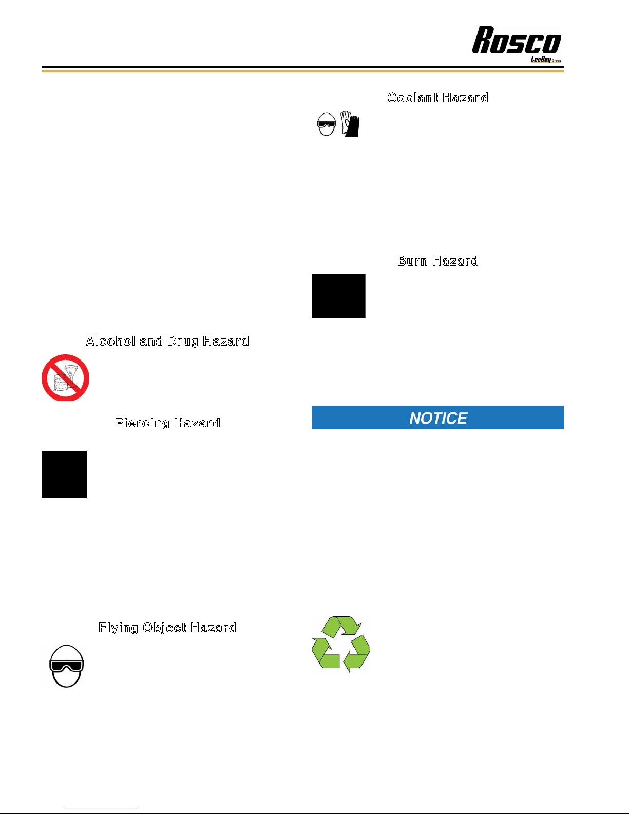
Alcohol and Drug Hazard
Never operate the machine while under the
inuence of alcohol, drugs, or when ill.
Coolant Hazard
Coolant must be handled properly to ensure
operator safety.
• Wear eye protection and rubber gloves when handling
engine coolant.
• If contact with the eyes occurs, ush eyes with clean
water for 15 minutes.
• If contact with skin occurs, wash immediately with
soap and clean water.
Burn Hazard
Some of the machine’s surfaces become
very hot during operation and shortly after
shutdown.
• Keep hands and other body parts away from hot
machine surfaces.
• Handle hot components with heat-resistant gloves.
Piercing Hazard
High-pressure hydraulic uid or fuel can
penetrate your skin and result in serious
injury. Avoid skin contact with high-pressure
hydraulic uid or diesel fuel spray caused
by a hydraulic or fuel system leak such as a
broken hydraulic hose or fuel injection line.
• If you are exposed to high-pressure hydraulic uid or
fuel spray, obtain prompt medical treatment.
• Never check for a hydraulic uid or fuel leak with your
hands. Always use a piece of wood or cardboard.
Have your authorized Rosco LeeBoy dealer or
distributor repair the damaged parts.
Flying Object Hazard
Always wear eye protection when cleaning
the Rosco CSV Chip Spreader with
compressed air or high-pressure water.
Dust, ying debris, compressed air,
pressurized water or steam may cause eye
injury.
The safety messages that follow have NOTICE level
hazards.
Any part that is found defective as a result of inspection
or any part whose measured value does not satisfy the
standard or limit must be replaced.
Always tighten components to the specied torque.
Loose parts can cause damage to the machine or cause
it to operate improperly.
Only use replacement parts approved by Rosco
LeeBoy. Other replacement parts may affect warranty
coverage.
Follow the guidelines of the EPA or other
governmental agencies for the proper
disposal of hazardous materials such as
engine oil, diesel fuel, and engine coolant.
Consult the local authorities or
reclamation facility.
Rosco CSV Variable Width Chip Spreader1-6
Page 21

Safety
Dispose of hazardous materials in accordance with
all applicable laws and regulations. Never dispose of
hazardous materials by dumping them into a sewer, on
the ground, or into groundwater or waterways.
Clean all accumulated dirt and debris away from the
body of the chip spreader and its components before
you inspect the chip spreader or perform preventive
maintenance procedures or repairs. Operating a
chip spreader with accumulated dirt and debris will
cause premature wear of chip spreader components.
Accumulated dirt and debris also hinders effective chip
spreader inspection.
Retrieve any tools or parts that may have dropped inside
of the chip spreader to avoid improper chip spreader
operation.
If any alert indicator illuminates during chip spreader
operation, stop the engine immediately and determine
the cause if you can. DO NOT operate the machine if it
needs repairs. Contact your authorized Rosco LeeBoy
dealer for assistance or service.
MACHINE PRECAUTIONS
Hot Material Precautions
• Wear protective gear for face, hands, feet, and body
when operating the chip spreader.
• Allow machine to cool before repairing or maintaining
working components.
• DO NOT remove radiator cap, drain plugs, service
grease ttings, or pressure taps while engine is hot.
Add coolant to the radiator and perform other services
only when the engine is stopped and fully cooled.
Hydraulic Systems Precautions
• Ensure all components are in good working condition.
Replace any worn, cut, abraded, attened or crimped
hoses and metal lines.
• DO NOT attempt makeshift repairs using tape, clamps
or cements. The hydraulic system operates under
extremely high pressure and such repairs could
cause serious injury.
1
• Wear proper hand and eye protection when checking
for a high pressure leak. Use a piece of wood or
cardboard as a back stop to isolate and identify leaks.
Hydraulic oil under pressure can
cause serious personal injury. Check for oil leaks
with a piece of cardboard. DO NOT expose hands to
possible high-pressure oil. Turn off engine before
attempting to tighten oil lines and ttings.
• Escaping pressurized hydraulic uid has force
sufcient to penetrate the skin, which could cause
serious personal injury. Ensure all pressure is
relieved before disconnecting line, hoses or valves.
• If injury from concentrated high-pressure steam
or hydraulic uid occurs, seek medical attention
immediately. Injuries resulting from hydraulic uid
penetrating the skin’s surface can result in serious
infections or toxic reactions.
Rosco CSV Variable Width Chip Spreader 1-7
Page 22

Safety
Refueling Precautions
• Do NOT overll the fuel tank as overow creates a re
hazard when spilled on hot components.
• DO NOT smoke when refueling and never refuel when
the engine is running. Fuel is highly ammable and
should be handled with care. Death or serious injury
can occur due to explosion and/or re.
• DO NOT ll tank to capacity. Allow room for expansion
to reduce the risk of fuel expanding and spilling from
the tank.
• Tighten fuel cap securely. Should fuel cap be lost,
replace it with an original manufacturer’s approved
cap. Pressurization of the tank may result from use of
non-approved cap.
• Prevent res by keeping the machine clean of
accumulated debris, grease, and spilled fuel.
• Use ultra-low sulfur diesel fuel (ULSD) only.
Battery Precautions
• Keep all sparks and ames away from batteries, as
gas given off by electrolytes is explosive.
• Acid propelled by an explosion can cause blindness
if it comes in contact with eyes. Always wear safety
glasses when working near batteries.
• If you come in contact with battery electrolyte solution,
wash off immediately. Chemicals can cause burns.
Starting and Stopping
Precautions
• Check all around the machine to make sure there are
no people working on the machine or in its path before
starting. DO NOT start until area is clear. Death or
serious injury can occur to bystanders from being
crushed under a moving machine.
• Check brakes, steering and other control devices in
accordance with instructions before starting. DO NOT
bypass the chip spreader neutral-start system.
DO NOT operate the engine in an
enclosed area without proper ventilation. Exhaust
gasses are odorless and deadly.
Parking Precautions
• Park machine on level ground whenever possible and
apply the parking brake.
• Before leaving operator’s station:
1. Place the truck in neutral and engage the parking
brake.
2. Turn off all accessories.
3. Shut off engine.
• Remove ignition key when leaving the machine parked
or unattended.
• Always disconnect the battery ground cable before
working on the electrical system to avoid injury from
spark or short circuit. Electrical shock and burns can
occur.
• To avoid electrolyte loss, DO NOT tip batteries more
than 45 degrees.
Operating Precautions
• The receiving hopper width is 10 feet when fully
extended. Use extreme caution while chip spreading
to avoid damage or accidents from trafc and
roadside obstacles.
• Always comply with local regulations regarding
moving equipment on public roads and highways.
• Know and use the hand signals required for a
particular job. Know who has the responsibility for
signaling.
• Make sure that all lights and reectors comply with
state and local regulations. Make sure that they are
clean, in good working order, and can be seen clearly
by all trafc.
Rosco CSV Variable Width Chip Spreader1-8
Page 23

Safety
• DO NOT stand between the equipment and the truck
while the truck is being backed to the chip spreader.
Death or serious injury can result from being crushed
between the two machines.
• Check all gauges and warning instruments for proper
operation. If malfunctions are found, shut down the
machine and report the problem for resolution. If the
failure causes loss of steering control, loss of brake
control, or loss of engine power, stop chip spreader
motion as quickly as possible. Apply parking brake.
Keep the machine securely parked until the failure is
corrected or the machine can be safely towed.
• Drive the machine with care. Make sure speed is
compatible with conditions. Use caution on rough
ground, slopes, and while turning.
• Be alert for hazards and obstructions such as ditches,
trees, cliffs, overhead power lines, and areas where
there is danger of a slide.
• Be aware of and understand the job site trafc ow
patterns.
• Obey agmen, road signs, and signals.
• Watch for bystanders. Never allow anyone to be
under the machine during operation. Never allow
anyone to reach into the machine during use.
• Operator must know how to use signaling devices
when driving the machine. Operator must also
understand which circumstances require use of each
signal. Use tail lights, slow moving vehicle signs, and
warning beacon as needed when traveling on public
roads. It is recommended that you provide an escort
on the road.
Maintenance Precautions
• DO NOT attempt repairs unless trained to do so.
Refer to manuals and experienced repair personnel
for help.
• Before working on the machine, securely block the
machine and any components that may fall. Block
any working components to prevent unexpected
movement while repairs are being made.
• Always wear safety glasses and other required safety
equipment when servicing or making repairs.
• Disconnect battery before working on the electrical
system or welding.
• Avoid lubrication or mechanical adjustments while
the chip spreader is in motion or while engine is
operating.
• Never make repairs on pressurized components such
as uid lines, the gas system, or mechanical items until
the pressure has been relieved.
• When servicing or replacing hardened pins, use a
brass drift or other suitable material between the
hammer and pin.
• Keep brake and steering systems in good operating
condition.
1
• DO NOT tow the machine, except to remove from road
or to load on trailer.
Storage Precautions
• Store machine in an area away from human activity.
• DO NOT permit children to play on or around the
stored machine.
• Make sure the unit is stored on a surface that is rm,
level, and free of debris.
• Store the machine inside a building or cover securely
with a weather-proof tarpaulin.
Rosco CSV Variable Width Chip Spreader 1-9
Page 24

Safety
SAFETY DECALS
If your machine is repainted, it is extremely important
that you replace all the CAUTION, WARNING and
DANGER safety decals in the proper locations. (Figure
1-1) For additional help, refer to the parts listing in
Section 7 and contact your authorized Rosco LeeBoy
dealer to order a replacement kit.
NOTE: It is the responsibility of the owner and
operator to make sure that all safety labels are
readable and located on the chip spreader as
designated by Rosco LeeBoy.
Figure 1-1. Safety Labels and Safety Label Locations
Rosco CSV Variable Width Chip Spreader1-10
Page 25
Safety
Safety Decals Care
1. Keep safety decals and signs clean and legible at all
times.
2. Become familiar with the content and the position
of each safety decal. Decals include important
information.
3. Replace decals and signs that are missing or
become impossible to read.
4. When replacing parts that display a safety decal,
ensure that the new part is tted with a decal as well.
5. Obtain replacement safety decals or signs from
your authorized Rosco LeeBoy dealer.
Decal Installation (Sticker Type)
1. Be sure that the installation area is clean and dry.
Use hot, soapy water to clean the surface where the
decal will be applied.
2. Thoroughly dry the surface.
3. Measure and t decal before removing the paper
backing.
Decal Installation (Top
Protected)
1. If the decal has a protective top paper, use hot
soapy water on the surface where the decal will be
applied. Leave wet.
2. Determine the proper location, remove protective
back paper and soak decal in clean soapy water
before application. This will help to alleviate air
bubbles in the applied decal.
3. Smooth decal into place with a squeegee and check
for air bubbles.
4. Small air pockets can be pierced with a pin and
smoothed out using a piece of the decal backing.
5. When decal is completely smoothed, carefully
remove top paper.
1
4. For decals with no top protection paper, remove the
smallest split-backed paper.
5. Align decal over the specied area and carefully
press exposed portion into place.
6. Slowly remove the remaining backing and carefully
smooth the remaining portion of the decal into
place.
7. Small air pockets can be pierced with a pin and
smoothed using a piece of the decal backing.
Rosco CSV Variable Width Chip Spreader 1-11
Page 26

Safety
NOTES
Rosco CSV Variable Width Chip Spreader1-12
Page 27

Section 2
INFORMATION AND SPECIFICATIONS
Page
Limited Warranty Policy . . . . . . . . . . . . . . . . . . . . . . . . . . 2-2
Contact Information . . . . . . . . . . . . . . . . . . . . . . . . . . . . 2-3
Specication Charts . . . . . . . . . . . . . . . . . . . . . . . . . . . . 2-4
Torque Specications . . . . . . . . . . . . . . . . . . . . . . . . . . . 2-7
Standard Inch Fasteners . . . . . . . . . . . . . . . . . . . . . . . 2-7
Metric Fasteners . . . . . . . . . . . . . . . . . . . . . . . . . . . 2-8
Hydraulic Fittings . . . . . . . . . . . . . . . . . . . . . . . . . . 2-8
Determining Proper Torque . . . . . . . . . . . . . . . . . . . . . 2-9
2
Rosco CSV Variable Width Chip Spreader
2-1
Page 28

Information and Specications
LIMITED WARRANTY POLICY
Warranty
Subject to the limitations, exclusions, and claims procedures set
forth herein, VT LeeBoy, Inc. warrants [to the rst retail purchaser]
that this product will be free from substantial defects in materials
and workmanship during the warranty period.
If a defect in material or workmanship is found, your authorized
LeeBoy Dealer is to be notied during the warranty period.
LeeBoy and its authorized Dealer will repair or replace any part or
component of the unit or part that fails to conform to the warranty
during the warranty period.
The warranty period will begin on the initial start-up, training and
delivery of the unit by the Dealer to the customer, and will expire
after twelve (12) months following the delivery of the product to the
rst retail purchaser. (See Dealer for additional warranty.)
Manufacturers’ Warranties: Engines are warranted by their
manufacturers and may have warranty coverage that differs from
that of LeeBoy. LeeBoy does not warrant any engine.
Replacement parts furnished by LeeBoy are covered for the
remainder of the warranty period applicable to the unit or
component in which such parts are installed.
LeeBoy has the right to repair any component or part before
replacing it with a new one.
All new replacement parts purchased by a LeeBoy Dealer will carry
a six-month warranty.
This Limited Warranty is governed by the laws of the State of North
Carolina.
THE FOREGOING WARRANTY IS EXCLUSIVE AND IN LIEU
OF ALL OTHER EXPRESSED, STATUTORY AND IMPLIED
WARRANTIES APPLICABLE TO UNITS, ENGINES, OR PARTS
INCLUDING WITHOUT LIMITATION, ALL IMPLIED WARRANTIES
OF MERCHANTABILITY OR FITNESS FOR ANY PARTICULAR USE
OR PURPOSE OR AGAINST INFRINGEMENT.
Items Not Covered
LeeBoy is not responsible for the following:
All used units or used parts of any kind.
Repairs due to normal wear and tear or brought about by abuse or
lack of maintenance of the machine.
Attachments not manufactured or installed by LeeBoy.
Liability for incidental or consequential damages of any type
including, but not limited to, lost prots or expenses of acquiring
replacement equipment.
Limitations
VT LeeBoy , Inc. has no obligation for:
Any defects caused by misuse, misapplication, negligence, accident,
or failure to maintain or use in accordance with the most current
operating instructions.
Unauthorized alterations.
Defects or failures caused by any replacement parts or attachments
not manufactured by or approved by LeeBoy.
Failure to conduct normal maintenance and operating service
including, without limitation, providing lubricants, coolant, fuel, tuneups, inspections, or adjustments.
Unreasonable delay, as established by LeeBoy, in making the
applicable units or parts available upon notication of a service notice
ordered by same.
Warranty Responsibility: The warranty responsibility on all engines
rests with the manufacturer of the engine.
Warranty and Parts Support: LeeBoy may have support agreements
with some engine manufacturers for warranty and parts support.
However, LeeBoy does not warrant the engine.
This Limited Warranty sets forth your sole remedy in connection
with the sale or use of the LeeBoy product covered by this Limited
Warranty.
This Limited Warranty extends only to the rst retail purchaser, and is
not transferable.
In the event any portion of this Limited Warranty shall be determined
to be invalid under any applicable law, such provision shall be deemed
null and void and the remainder of the Limited Warranty shall continue
in full force and effect.
Other Limitations
IN NO EVENT, WHETHER AS A RESULT OF BREACH OF CONTRACT
OR WARRANTY OR ALLEGED NEGLIGENCE OR LIABILITY WITHOUT
FAULT, SHALL LEEBOY BE LIABLE FOR SPECIAL, INCIDENTAL OR
CONSEQUENTIAL DAMAGES INCLUDING, WITHOUT LIMITATION,
LOSS OF PROFIT OR REVENUE, COST OF CAPITAL, COST
OF SUBSTITUTED EQUIPMENT, FACILITIES OR SERVICES,
DOWNTIME COSTS, LABOR COSTS OR CLAIMS OF CUSTOMERS,
PURCHASERS OR LESSEES FOR SUCH DAMAGES. IN NO EVENT
WILL WARRANTY COMPENSATION, OR OTHER DAMAGES
AVAILABLE FROM LEEBOY EXCEED THE PURCHASE PRICE OF
THE PRODUCT.
2-2
Rosco CSV Variable Width Chip Spreader
Page 29

CONTACT INFORMATION
Information and Specications
For information regarding parts and repairs about your
Rosco LeeBoy product, contact your authorized LeeBoy
dealer. If your dealer is unable to resolve the problem,
contact LeeBoy directly.
Sales Representative:
Dealership Name:
Dealership Address:
Dealership Phone:
Record dealer information in the space provided. For
additional information about Rosco LeeBoy, please visit:
www.leeboy.com.
Record of Ownership
Please complete the following information for use if you need to contact LeeBoy for service, parts or literature.
Machine Model Number:
Product Serial Number:
Date of Purchase:
Nameplate
2
The nameplate contains the model and serial numbers used to identify the machine and its components for parts or
service information. Refer to the Engine Operator’s Manual for the location of the engine nameplate.
Figure 2-1. Nameplate Location
Rosco CSV Variable Width Chip Spreader
2-3
Page 30
Information and Specications
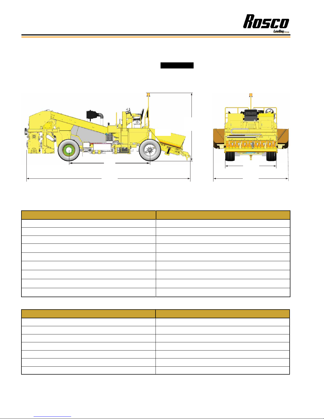
SPECIFICATION CHARTS
The specications provided in this section include
screed weights, dimensions, performance, and torque
values for both metric and standard inch fastener.
13’
(4 m)
26’
(8 m)
Table 2-1. Machine Dimensions
ITEM SPECIFICATION
Overall Length 26 ft (8 m)
Overall Height with Beacon Extended 10 ft 8 in (3.3 m)
Overall Width (Outside Front Tires) 8 ft 6 in (2.6 m)
Overall Weight 23,720 lbs (10759 kg)
components approved by Rosco LeeBoy.
Replace original equipment only with
10’ 8”
(3.3 m)
6’ 4.5”
(2 m)
10’
(3.04 m)
Wheelbase 13 ft (3.9 m)
Outside Turning Radius 20 ft 6 in (6.2 m)
Minimum Ground Clearance 7 in (18 cm)
Track Width (Front) 6 ft 4.5 in (2 m)
Track Width (Rear) 7 ft 7 in (2.3 m)
Table 2-2. Engine Specications
ITEM SPECIFICATION
Model Cummins QSB6.7, Tier 4F
Engine Type 6-Cylinder, Water-Cooled Diesel
Horsepower 275 HP
Rated Speed 2200 RPMs
Displacement, Bore and Stroke 402 cu in (6.7 L); 4.10 in (105 mm); 5 in (127 mm)
High Idle Speed 900 RPMs
Maximum Gross Torque 730 ft lbs
2-4
Rosco CSV Variable Width Chip Spreader
Page 31

Information and Specications
Table 2-3. Electrical Specications
ITEM SPECIFICATION
Batteries (2) 12 Vdc Maintenance Free
Cold Cranking Amps (CCA) 1000 CCA
Alternator 130 amp
Table 2-5. Operational Specications
Work Speed / Travel Speed 8 mph (12.8 kph) / 20 mph (32.2 kph)
Conveyor Belt Speed (Maximum) 500 FPM
Minimum / Maximum Spread Width 1 - 16 ft (.3 - 4.9 m)
Gradeability Percentage 9% Fully Loaded
Table 2-6. System Pressures
ITEM SPECIFICATION
Drive 5800 psi (399.9 Bar)
Propulsion Motor Displacement 160 cc (.16 L)
Propulsion Pump Displacement and Relief Pressure 165 cc (.16 L); 5800 psi (399.9 Bar)
Hydraulic Cooler Electric 11,000 btu/hr (3.2 kW/hr)
Auxiliary Pump Displacement and Relief Pressure 130 cc (130 ml); 2500 psi (172.4 Bar)
Standby Pressure 350 psi (24.1 Bar)
2
Table 2-7. Fuel and Lubricant Specications
ITEM SPECIFICATION
Engine Oil 15W-40
Hydraulic Oil 5W20 AWAT OIL
Coolant Ethylene/Glycol or Propylene Glycol
Fuel Ultra Low Sulphur Diesel (ULSD)
Transfer Case (2-Speed) 90 WT Motor Oil
Differential Oil 90 WT Motor Oil
Gear Box 90 WT Motor Oil
Grease Shell Avania EP Grease or Equivalent
Table 2-8. Machine System Capacity Specications
ITEM SPECIFICATION
Fuel 50 gal (189 L)
Engine Lubrication Oil 17.6 qt (16.6 L)
Engine Coolant 32 qt (30.3 L)
Hydraulic Oil Reservoir 75 gal (283.9 L)
Rosco CSV Variable Width Chip Spreader
2-5
Page 32

Information and Specications
Table 2-9. Hopper Specications
ITEM SPECIFICATION
Front Width 0 - 16 ft (0 - 4.87 m)
Front Capacity 4 cu yd
Rear Capacity 3.5 cu yd
Control Individual Gate Control
Table 2-10. Conveyor, Auger and Spread Roll Motors
ITEM SPECIFICATION
Conveyor Motor Displacement 254cc (254 ml)
Conveyor Motor Maximum Output Speed 230 RPMs
Auger Motor Displacement 200 cc (200 ml)
Auger Motor Maximum Output Speed 230 RPMs
Spread Roll Motor Displacement 141 cc (141 ml)
Spread Roll Motor Maximum Output Speed 153 RPMs
Table 2-11. Miscellaneous Specications
ITEM SPECIFICATION
Tire Size 385/65R22.50
Pump (Fan Drive, Steering, Brakes) Displacement 45 cc (45 ml)
Pump (Fan Drive, Steering, Brakes) Relief Pressure 3000 psi (206.8 Bar)
Drive Axle Load Capacity 52,900 lbs (23,995 kg)
2-6
Rosco CSV Variable Width Chip Spreader
Page 33

TORQUE SPECIFICATIONS
Information and Specications
The following tables list torque values for standard
hardware. This is a guide for average application
involving typical stresses and machined surfaces.
Values are based upon physical limitations of clean,
plated and lubricated hardware. Under more extreme
conditions, individual torque value should be followed.
Conversion formulas are provided in the adjacent table:
ft-lb to N•m [ft-lb]*1.3558 = [N•m)
ft-lb to in-lb [ft-lb]*12 = [in-lb]
N•m to in-lb [N•m]*8.8508 = [in-lb]
Conversion Formula
Standard Inch Fasteners
Table 2-12. Torque Specications For Standard Inch Fasteners
CAPSCREWS: SAE GRADE 5 CAPSCREWS: SAE GRADE 8
SIZE THREAD
1/4 20 UNC 8 6 11 8 12 9 16 12
28 UNF 10 7 14 9 14 10 19 14
5/16 18 UNC 17 13 23 18 25 18 34 24
24 UNF 19 15 26 20 27 20 37 27
3/8 16 UNC 31 23 42 31 44 33 60 45
24 UNF 35 26 47 35 49 37 66 50
7/16 14 UNC 49 37 66 50 70 52 95 71
20 UNF 55 41 75 56 78 58 106 79
1/2 13 UNC 75 57 102 77 106 80 144 108
20 UNF 85 64 115 87 120 90 163 122
9/16 12 UNC 109 82 148 111 154 115 209 156
18 UNF 121 91 164 123 171 128 232 174
5/8 11 UNC 150 113
18 UNF 170 127 230 172 240 180 325 244
3/4 10 UNC 267 200 362 271 376 282 510 382
16 UNF 297 223 403 302 420 315 569 427
7/8 9 UNC 429 322 582 437 606 455 822 617
14 UNF 474 355 643 481 669 502 907 681
1 8 UNC 644 483 873 655 909 681 1232 923
14 UNF 722 542 979 735 1020 765 1383 1037
1-1/4 7 UNC 1121 840 1520 1139 1817 1363 2464 1848
12 UNF 1241 930 1683 1261 2012 1509 2728 2046
1-1/2 6 UNC 1950 1462 2644 1982 3162 2371 4287 3215
12 UNF 2194 1645 2975 2230 3557 2668 4823 3617
TORQUE (ft lb) TORQUE N•m TORQUE (ft lb) TORQUE N•m
Dry Lubed Dry Lubed Dry Lubed Dry Lubed
203 153 212 159 287 216
2
Rosco CSV Variable Width Chip Spreader
2-7
Page 34

Information and Specications
Metric Fasteners
Table 2-13. Torque Specications for Metric Fasteners
CLASS 8.8 [GRADE 5 EQUIVALENT] CLASS 10.9 [GRADE 8 EQUIVALENT]
NOMINAL SIZE
AND PITCH
M4 x 0.7 2 2 3 2 3 2 4 3
M5 x 0.8 5 3 7 4 7 5 9 7
M6 x 1 8 6 11 8 11 8 15 11
M8 x 1.25 19 14 26 19 27 20 37 27
M10 x 1.5 37 28 50 38 53 40 72 54
M12 x 1.75 65 49 88 66 93 70 126 95
M14 x 2 104 78 141 106 148 111 201 150
M16 x 2 161 121 218 164 230 173 312 235
M18 x 2.5 222 167 301 226 318 239 431 324
M20 x 2.5 314 236 426 320 449 337 609 457
M22 x 2.5 428 321 580 435 613 460 831 624
M24 x 3 543 407 736 552 777 582 1053 789
M27 x 3 796 597 1079 809 1139 854 1544 1158
M30 x 3.5
TORQUE (ft lb) TORQUE N•m TORQUE (ft lb) TORQUE N•m
Dry Lubed Dry Lubed Dry Lubed Dry Lubed
1079 809 1463 1097 1544 1158 2093 1570
Hydraulic Fittings
Tightening Flare-Type Tube Fittings
1. Check the are and are seat for defects that might
cause leakage.
2. Align tube with tting before tightening.
3. Lubricate connection.
4. Hand tighten swivel nut until snug.
5. To prevent twisting the tube(s), use two wrenches.
Place one wrench on the connector body and
tighten the swivel nut with the second to the torque
shown in the following table:
NOTE: The torque values shown are based upon
lubricated connections.
Table 2-14. Torque Specications for Steel Flare
Type Tube Fittings
TUBE SIZE
OUTER
DIAMETER
(IN) (IN) (LB FT) (N•m)
3/16 7/16 8 11
1/4 9/16 12 16
5/16 5/8 16 22
3/8 11/16 23 31
1/2 7/8 38 52
5/8 1 54 73
3/4 1 1/4 75 102
7/8 1 3/8 83 113
NUT SIZE
ACROSS
FLATS
TORQUE VALUE
2-8
Rosco CSV Variable Width Chip Spreader
Page 35

Determining Proper Torque
LA
L
E
LA
LH
The only reliable method of creating a consistently
leak-free and long-lasting connection is to ensure the
coupling is brought to the proper torque. Using a torque
wrench with crowfoot is the best method, but the ats
method can be used if a torque wrench is not available.
The most straightforward method of determining the
correct torque setting is to multiply the desired torque
by the length of the wrench from the center of the handle
to the center of the drive (L); divided by the length of the
wrench from the center of the handle to the crowfoot
center (LA) as shown below:
L
Figure 2-15. Torque Wrench - Crowfoot
Information and Specications
2
The minimum torque values are
adequate for sealing most applications. Maximum
torque values should never be exceeded.
There are several methods of determining the correct
setting on the torque wrench when using a crowfoot. All
of the methods involve making the setting proportional
to the effective change in length of the wrench multiplied
by the desired nal torque. The equations and
illustration below describe proper measurements.
Equations
• Torque setting if the crowfoot is placed in line with
respect to the wrench:
TS = TD * L / LA
OR
TS = TD * L / (L+E)
• Torque setting if the crowfoot is placed at 90° with
respect to the wrench
TS = TD * L / LH
OR
TS = TD * L / √(L2 + E2)
• To estimate the crowfoot size (E)
Figure 2-16. Measurements Needed
LEGEND
L = Distance from center of torque wrench handle to the
center of socket drive
E = Distance from center of socket drive to the center of
crowfoot
LA = Distance from center of torque wrench handle to
the center of crowfoot
LH = Distance from center of torque wrench handle to
the center of crowfoot, when mounted at 90°
TD = Desired torque at the tting
TS = Torque setting indicated on wrench
E = Drive Size * 0.5 + Distance between Drive and
Open End + Wrench Size * 0.5774
Rosco CSV Variable Width Chip Spreader
2-9
Page 36

Mark Line on Nut
Information and Specications
Coupling Installation
Use the following steps for proper coupling installation:
1. Determine the correct torque value for your
coupling.
NOTE: Only use the torque values specied from
the manufacturer. DO NOT use SAE torque
recommendations.
2. Ensure the seal face and threads are clean and in
good condition. O-Rings should be lubricated with
light oil, but threads should be completely dry unless
making pipe thread connections (interference seal).
NOTE: Attach the male end of the hose onto the
equipment rst since it may be necessary to
rotate the entire hose assembly to tighten
the male threads. Then route the hose into
position while avoiding twisting the hose.
3. Tighten the connection (by hand), bringing the seal
face into contact and rotating the nut until it stops.
4. Mark a line across the coupling nut and backup hex
for the ats method verication of coupling torque.
5. Apply a wrench to the backup hex to prevent the
coupling and hose from moving while tightening the
nut with a torque wrench.
Failure to retain the backup hex during
installation will also result in additional clamp load
force that could cause damage to the seal face.
NOTE: The coupling nut must be in motion for an
accurate torque reading. If the nut is stopped
before nal torque value is achieved, it must
be loosened and retightened until the torque
is attained while the nut is in motion.
If a torque wrench cannot t into the coupling area or if
it is unavailable, the ats method may be used to ensure
that the coupling is properly tightened.
Example 2 Flats
difference
Figure 2-17. Flats Method Tightening
NOTE: The mark placed on the nut and backup hex
after tightening by hand should rotate during
nal tightening according to the table below.
The nut and backup hex can then be marked
to indicate if the coupling loosens over time.
Table 2-18. Flats Method Values for Selected
Terminations
FLATS METHOD VALUES
Termination
Type
JIC -4 1.5 - 1.75
JIC -6 1.0 - 1.5
JIC -8 1.5 - 1.75
JIC -10 1.0 - 1.5
JIC -12 1.0 - 1.5
JIC -16 .75 - 1.0
JIC -20 .75 - 1.0
JIC -24 .75 - 1.0
JIC -32 .75 - 1.0
JIS -4 .5 - 1.5
1. Seal faces must be in contact with the tting fully
tightened by hand before marking ats.
2. The ats method is most accurate for the rst
assembly cycle. For multiple disassembly and
assembly cycles, torque values are more reliable.
Dash Size Flats
2-10
3. Tightening two (2) ats or more may damage seal
faces.
Rosco CSV Variable Width Chip Spreader
Page 37

Information and Specications
Table 2-19. Torque Specications For US Style Coupling Terminations
JIC, SAE 45°, ORFS, O-RING BOSS, GATES ADAPTERLESS AND MEGASEAL
JIC 37°, SAE 45°
DASH
SIZE
-3 8 10
-4 10 11 5 6 10 12 14 16 14 16
-5 13 15 7 9 18 20
-6 17 19 12 15 18 20 24 26 24 26
-8 34 38 20 24 32 40 37 44 50 60
-10 50 56 34 40 46 56 50 60 72 80
-12 70 78 53 60 65 80 75 83 125 135
-14 65 80 160 180
-16 94 104 74 82 92 105 111 125 200 220
-20 124 138 75 83 125 140 133 152 210 280
-24 156 173 79 87 150 180 156 184 270 360
-32 219
& Mega-Seal
(Steel)
Min Max Min Max Min Max Min Max Min Max
243 158 175
JIC 37°, SAE 45°
& Mega-Seal
(Brass)
Flat Face O-Ring
Seal (Steel)
SAE O-Ring Boss
(Steel) & Gates
Adapterless
≤ 4000 PSI
SAE O-Ring Boss
(Steel) & Gates
Adapterless
> 4000 PSI
2
Table 2-20. Torque Specications for DIN 24, DIN 60,
and Inverted Cone Style Coupling Terminations
DIN 24, DIN 60, AND INVERTED CONE
Size (mm) Torque (lb ft)
Light
Series
Tube OD
6 7 15
8 15 26
10 8 18 30
12 10 22 33
14 12 26 37
15 14 30 52
18 20 44 74
22 25 59 89
28 30 74 111
35 133 184
42 148 221
Heavy
Series
Tube OD
16 30 52
38 74 162
Min Max
Table 2-21. Torque Specications for 4-Bolt
Flange Connections
4-BOLT FLANGES
Dash Size Bolt Size (in) Torque (lb ft)
-8 0.31 17
-12 0.38 26
-16 0.44 43
-20 0.50 65
-24 0.63 130
-32 0.75 220
1. Align faces and tighten bolts (by hand) before
applying nal torque in a pattern. The seal faces
must be parallel with an even bolt tension to seal
properly.
2. Torque values apply to bolts that are plated or
coated in light engine oil.
3. Before assembly, lubricate O-Ring with light oil
(SAE 10W or 20W).
Rosco CSV Variable Width Chip Spreader
2-11
Page 38

Information and Specications
Table 2-22. Torque Specications for NPTF Dry Seal
Pipe Threads
NPTF
Dash Size Max Torque (ft-lb)
-2 20
-4 25
-6 35
-8 45
-12 55
-16 65
-20 80
-24 95
-32 120
1. The torque values obtained from tightening pipe
threads can vary considerably depending upon
thread condition. Adequate sealing can occur at
values much lower than the maximum values listed
above. Only enough torque to achieve adequate
sealing should be used.
2. When using a male tapered pipe thread with a
female straight or parallel pipe thread, maximum
values are 50% of those listed in the table above.
Table 2-23. Torque Specications for BSP 30°
Inverted Cone and JIS Coupling Terminations
BSP 30° INVERTED CONE AND JIS
Torque (ft-lb)
Dash Size
Min Max
-2 7 9
-4 11 18
-6 19 28
-8 30 36
-10 37 44
-12 50 60
-16 79 95
-20 127 152
-24 167 190
-32 262 314
3. If thread sealant is used, maximum values shown
should be decreased by 25%.
2-12
Rosco CSV Variable Width Chip Spreader
Page 39

Section 3
COMPONENT LOCATION
Page
Components Overview . . . . . . . . . . . . . . . . . . . . . . . . . . . 3-3
Engine . . . . . . . . . . . . . . . . . . . . . . . . . . . . . . . . 3-3
Operator Platform . . . . . . . . . . . . . . . . . . . . . . . . . . 3-3
Electrical System . . . . . . . . . . . . . . . . . . . . . . . . . . 3-3
Receiving Hopper . . . . . . . . . . . . . . . . . . . . . . . . . . 3-4
Conveyors . . . . . . . . . . . . . . . . . . . . . . . . . . . . . . 3-4
Spread Hopper . . . . . . . . . . . . . . . . . . . . . . . . . . . 3-5
Hydrostatic Drive . . . . . . . . . . . . . . . . . . . . . . . . . . 3-5
Machine Overview . . . . . . . . . . . . . . . . . . . . . . . . . . . . . 3-6
Operator Station . . . . . . . . . . . . . . . . . . . . . . . . . . . . . . 3-7
Control Panel . . . . . . . . . . . . . . . . . . . . . . . . . . . . . . . 3-8
Joystick Controls . . . . . . . . . . . . . . . . . . . . . . . . . . . . . . 3-10
3
3-1Rosco CSV Variable Width Chip Spreader
Page 40

Components
NOTES
Rosco CSV Variable Width Chip Spreader3-2
Page 41

Components
COMPONENTS OVERVIEW
The Rosco CSV Variable Width Chip Spreader applies
a uniform, even layer of aggregate without gaps or
overlaps. Equipped with a receiving hopper in the rear,
two belt conveyors carry aggregate to the front spread
hopper that hydraulically extends to a width of up to
16 feet. Computerized controls allow the hydraulic
discharge gates to open and close to deliver aggregate
at a constant rate, while the vibratory hopper improves
discharge uniformity. An economical means of paving
rural roads, parking lots and subdivision streets, the
CSV chip spreader is easy to operate and maintain.
Become familiar with its components before operating
this machine.
Operator Platform
The operator platform allows easy and convenient
access for machine controls and chip spreader
functions. One person can operate the chip spreader
with ease. A dual operator station option is available.
The control panel(s) features a cover that can be closed
to protect operator control components. The control
panel column can also be tilted forward to allow more
room on the platform if needed.
3
Engine
The CSV Variable Width Chip Spreader is equipped
with a Cummins QSB6.7 Tier 4F diesel engine. The
air cleaner mounted on top of the machine removes
ne particles such as dust, sand, and chaff. The fuel
lter removes contaminants from diesel fuel before it
ows into the injection pump. The radiator mounted
in front cools the engine. The hydraulically-driven fan
removes heat, saves horsepower and reduces noise.
The fan reverses every 30 minutes to clean the radiator
and spins low RPMs when conditions permit. As the
temperature rises, the fan picks up speed.
The CSV chip spreader features the latest in engine
technology. Tier 4 engines comply with emission
requirements established by the U.S. Environmental
Protection Agency (EPA) to reduce diesel particulate
matter (DPM) and other toxins released into the air.
Advanced emission-control devices and low-sulfur fuel
requirements--only Ultra-Low Sulfur Diesel (ULSD)
can be used in this engine--combine with new aftertreatment methods. Refer to the Engine Operator’s
Manual accompanying your chip spreader for additional
engine information.
Electrical System
The electrical system is powered by two 12-volt batteries
mounted in a battery compartment on the frame. Each
battery produces 12 volts DC and maintains 1000 cold
cranking amperes (CCA). An engine-mounted alternator
with 130 amperes of charging capacity keeps the
batteries charged during normal operation. The battery
charge rate can be monitored using the voltmeter on the
center operator control panel.
3-3Rosco CSV Variable Width Chip Spreader
Page 42

Components
Receiving Hopper
The receiving hopper on the rear of the machine is
hydraulically controlled. When the hopper wings are
fully open, the hopper can hold a payload up to 3.5 cubic
yards (4 cubic meters). The receiving hopper controls
are located on the joystick for ease of operation while
chip spreading.
Conveyors
The conveyors are an important part of the chip
spreader’s aggregate delivery system.
Two motor-driven conveyor belts move aggregate from
the receiving hopper to the spread hopper. Rubber
chute liners seal each side of the conveyors to prevent
spillage of aggregate. Drive, tension and suspension
for the conveyor belts are provided by various pulleys
attached to the conveyor frame. Pulleys and trough
idlers provide suspension and tension adjustment for
each conveyor belt.
Aggregate material is delivered by a dump truck into
the receiving hopper. The chip spreader is equipped
with a positive-latching, hydraulic-release truck hitch
that secures the chip spreader to a pull bar on the
dump truck. Rubber sealing skirts along the receiving
hopper seals the hopper to the truck dump box during
operation.
Once aggregate material is loaded into the receiving
hopper, it then moves via two hydraulic motor-driven
conveyor belts through grizzly screens to the front
spread hopper. The grizzly screens prevent oversized
aggregate and debris from entering the spread hopper.
A feed gate for each conveyor in the receiving hopper
allows more control over the amount of aggregate
being conveyed to the spread hopper in the front of the
machine.
Proper alignment and tension adjustment of the
conveyor belts is necessary for optimum operation and
machine maintenance.
Rosco CSV Variable Width Chip Spreader3-4
Page 43

Spread Hopper
The spread hopper in front of the machine provides
accurate application of the aggregate to the road
surface. The spread hopper is hydraulically controlled
and extends from eight (8) feet (2.44 meters) to 16 feet
(4.87 meters) wide to meet job specications. Grizzly
screens at the top of the spread hopper prevent
oversized aggregate or other debris from entering the
spread hopper.
An auger shaft inside the
spread hopper rotates to
transfer aggregate outward
to the spread hopper evenly,
driven by a hydraulic motor
through a sprocket gear and
chain arrangement. The
spread roll at the bottom of
the spread hopper moves
aggregate out of the hopper
through the cut-off gates to
spread evenly onto the road
surface. Individual cut-off
gates allow spreading width
adjustments in six-inch
increments to the full width
of the hopper. The operator
can engage or disengage
individual cut-off gates
manually or automatically.
Components
Hydrostatic Drive
The Rosco Model CSV Variable Width Chip Spreader is
powered by a diesel engine with dual-range, hydrostatic
drive system that propels the machine forward or
reverse at varying speeds with dynamic braking action.
Components of the hydrostatic drive system include:
• One variable displacement axial piston pump coupled
to the diesel engine.
• One high-torque, bent-axis hydraulic motor at the front
axle, which receives hydrostatic power from the pump.
The machine offers three operational modes to
accommodate a wide range of chip spreading
requirements:
• Automatic: A programmable mode that allows the
operator to pre-set the maximum ground speed for
accurate and repeatable applications. Top speed in
Low Automatic is approximately 880 feet per minute
(268.2 meters per minute), or 10 mph (16 km/h),
depending upon engine and tire options. At speeds
less than the set maximum speed, the operator has
full control.
• Manual: A programmable mode that allows the
operator to adjust ground speed and direction with the
joystick. Top speed in Low Manual is the same as in
Low Automatic. The receiving hopper, spread hopper
and seat slides must be retracted to operate in Travel
Mode. (Page 4-5)
• Travel Mode: This programmable mode allows the
operator to adjust ground speed for travel between
job sites. The machine’s top speed is 20 mph (32
kph).
3
3-5Rosco CSV Variable Width Chip Spreader
Page 44

2
Components
MACHINE OVERVIEW
1
3
ITEM
NO.
1 Receiving Hopper
2 Operator Station(s)
3 Conveyors
4 Spread Hopper
CONTROL NAME FUNCTION
4
Figure 3-1. Operation Panels and Controls
Receives and holds aggregate material as conveyors move material to the
front of the chip spreader for distribution onto the road surface. Flow gates
in the receiving hopper, one on each side, permits control over the amount of
aggregate being conveyed to the spread hopper.
Contains steering wheel, brake pedal, and various machine and spreader
system controls. An option for two operator stations is available.
Dual conveyor belts move aggregate from the receiving hopper in the rear to
the spread hopper on front of the machine. The conveyor feed rate can be
controlled individually, manually or automatically from the operator stations.
The spread hopper covers the entire front of the machine. Grizzly screens
at the top of the spread hopper prevent oversized aggregate and debris
from entering the hopper. Augers move the aggregate to the outside ends
of the spread hoppers. The spreadroll at the bottom then applies aggregate
uniformly to the road surface. The two spread hoppers can be hydraulically
extended to a total width of 16 feet.
Rosco CSV Variable Width Chip Spreader3-6
Page 45

OPERATOR STATION
1
Components
2
5
3
4
Figure 3-2. Operator Station(s)
ITEM
NO.
1 Foot Brake Pedal Depressing the foot brake pedal stops the machine.
2 Steering Wheel with Horn
3 Joystick Controls
4 Control Panel
5
6
CONTROL NAME FUNCTION
Steers the machine. Includes horn and turn signal indicator lever.
It is recommended that the operator always sound the horn before starting
the engine to alert others that this large industrial machine is about to start
moving.
The joystick is an added convenience for the operator to control the
receiving hopper wings and truck hitch while spreading. A single button
on the back side of the joystick engages the spread hopper to release the
aggregate onto the road surface.
Contains machine and chip spreading controls, and the DP710 Digital Display
control unit. (Pages 3-8 and 3-9)
Extending/Retracting
Operator Station Platform
Operator Station Access
Ladder
Operator station platform hydraulically extends and retracts 15 inches (38.1
cm), providing an unrestricted view for accurate chip spreading.
Provides access to the operator station. The operator station is located on
the left side of the machine. Dual operator stations is an additional option.
6
3
3-7Rosco CSV Variable Width Chip Spreader
Page 46

Components
CONTROL PANEL
1
2
12
13
3
4
5
6
7
8
9
10
11
19
20
14 15 16 17 18
Figure 3-3. Control Panel
ITEM
NO.
CONTROL NAME FUNCTION
Digital display for operational and engine monitoring functions (i.e., oil
1 DP710 Digital Display
pressure, voltage, fuel level), system faults, and manual/automatic mode for
machine components. (See Page 4-7)
2 Joystick
The joystick is an added convenience for the operator for controlling the
receiving hopper, truck hitch position and spreading aggregate. (Page 3-10)
3 Park Brake Always set the park brake when the machine is parked.
4 Left Auger Manual/Auto
Sets the left spread hopper auger to operate either automatically or in
manual mode.
Sets the left auger speed when the auger is set to the manual mode. The
5 Left Auger Speed
operator can choose from three (3) speed options (the button will illuminate
red, amber or green): 60 RPMs (red); 120 RPMs (amber); or 180 RPMs
(green).
6 Left Conveyor Manual/Auto Sets the left conveyor to operate either automatically or in manual mode.
Sets the left conveyor speed when the conveyor is set to the manual
7 Left Conveyor Speed
mode. The operator can choose from ve (5) speed options (the button will
illuminate colors accordingly): 70 RPMs (red); 105 RPMs (amber); 140 RPMs
(pink); 185 RPMs (blue); or 230 RPMs (green).
8 Right Auger Manual/Auto
Sets the right spread hopper auger to operate either automatically or in
manual mode.
Sets the right auger speed when the auger is set to the manual mode. The
9 Right Auger Speed
operator can choose from three (3) speed options (the button will illuminate
red, amber or green): 60 RPMs (red); 120 RPMs (amber); or 180 RPMs
(green).
Rosco CSV Variable Width Chip Spreader3-8
Page 47

Components
ITEM
NO.
10
11 Conveyor Speed
12
13
14
15
16 Travel Mode
17
18
19 Emergency Stop
20 Ignition Switch Starts and stops engine.
CONTROL NAME FUNCTION
Right Conveyor Manual/
Auto
Individual Left Spread
Hopper Gates
Individual Right Spread
Hopper Gates
Left Spread Hopper
Extension
Main Left Spread Hopper
Gate
Main Right Spread Hopper
Gate
Right Spread Hopper
Extension
Sets the right conveyor to operate either automatically or in manual mode.
Sets the left conveyor speed when the conveyor is set to the manual
mode. The operator can choose from ve (5) speed options (the button will
illuminate colors accordingly): 70 RPMs (red); 105 RPMs (amber); 140 RPMs
(pink); 185 RPMs (blue); or 230 RPMs (green).
Each of the eight (8) buttons controls a one-foot section of the left spread
hopper. When the machine is stationary (in manual mode), all gates that can
be used illuminate yellow. Upon chip spreading, the yellow light will turn to
green signifying that the gates are open. You can decide to shut off any of
the gates by pressing the switch to close (the light will turn red).
Each of the eight (8) buttons controls a one-foot section of the right spread
hopper. When the machine is stationary (in manual mode), all gates that can
be used illuminate yellow. Upon chip spreading, the yellow light will turn to
green signifying that the gates are open. You can decide to shut off any of
the gates by pressing the switch to close (the light will turn red).
Used to move the left spread hopper extension in and out from 4 - 8 feet (1.2
- 2.4 m). Push switch to the left arrow position ({) to extend left. Push switch
to the right arrow position (}) to move in the left extension.
Opens and closes the left spreader hopper gate when operating in the
manual mode. To preset the gate opening, depress the button to the desired
size. The gate set-point size will show on the DP710 digital display.
Depressing the travel mode switch backward switches the machine into
AUTO mode. In order to operate in travel mode, the hopper wings must
be retracted and the operator seats must be locked into position. If these
conditions are not met, the travel button light will blink red and the machine
will not move into travel mode. The light becomes solid green when these
conditions are met.
Opens and closes the right spreader hopper gate when operating in the
manual mode. To preset the gate opening, depress the button to the desired
size. The gate set-point size will show on the DP710 digital display.
Used to move the right spread hopper extension in and out from 4 - 8 feet
(1.2 - 2.4 m). Push switch to the right arrow position (}) to extend right. Push
switch to the left arrow position ({) to move in the right extension.
Immediately stops the machine and all electronic functions. Turn clockwise
to release the emergency stop.
3
3-9Rosco CSV Variable Width Chip Spreader
Page 48

Components
JOYSTICK CONTROLS
Joystick controls is an added convenience for
operating the receiving hopper components and
activating the aggregate spreading onto the road
surface. Five buttons on the front of the joystick
control the truck hitch and opening/closing the
receiving hopper wings. A button on the back
side of the joystick is conveniently placed for
ease of grip and starts the aggregate ow for chip
spreading.
The truck hitch secures the chip spreader to the
pull bar on the aggregate dump truck. After the
positioning the hitch using the up and down buttons,
the hitch automatically locks. The center button
releases the truck hitch.
Figure 3-4. Joystick Controls
ITEM
NO.
1 Truck Hitch Release Releases the truck hitch.
2
3
4 Truck Hitch Up
5 Truck Hitch Down
6 Chipping Activation Press this button to start spreading aggregate onto the road surface.
CONTROL NAME FUNCTION
Receiving Hopper Wings
Up
Receiving Hopper Wings
Down
Push button to retract the receiving hopper wings (closes hopper).
NOTE: DO NOT close the receiving hopper while dump truck is still
hitched or in close proximity to the machine.
Push button to extend the receiving hopper wings (opens hopper).
NOTE: DO NOT open the receiving hopper while dump truck is still
hitched or in close proximity to the machine.
Pushing this button raises the truck hitch. It is critical that the aggregate
delivery truck is hooked to the hitch accurately.
Pushing this button lowers the truck hitch. It is critical that the aggregate
delivery truck is hooked to the hitch accurately.
2
3
1
4
5
Back of
Joystick
6
Rosco CSV Variable Width Chip Spreader3-10
Page 49

Section 4
OPERATION
Page
General Information . . . . . . . . . . . . . . . . . . . . . . . . . . . . 4-3
Receiving the Machine . . . . . . . . . . . . . . . . . . . . . . . . . . . 4-3
Initial and Daily Inspection
Start-Up Procedure
Starting the Engine . . . . . . . . . . . . . . . . . . . . . . . . . . 4-4
Stopping the Engine . . . . . . . . . . . . . . . . . . . . . . . . . 4-4
Driving the Machine . . . . . . . . . . . . . . . . . . . . . . . . . . . . 4-5
Travel Mode
Manual Mode
Auto Mode . . . . . . . . . . . . . . . . . . . . . . . . . . . . . . 4-5
Position Control Panel . . . . . . . . . . . . . . . . . . . . . . . . 4-6
Extend/Retract Operator Station . . . . . . . . . . . . . . . . . . . 4-6
Diesel Exhaust Fluid (DEF) After-Treatment System
DP710 Digital Display
Activate Control Console . . . . . . . . . . . . . . . . . . . . . . . 4-7
Main Screen . . . . . . . . . . . . . . . . . . . . . . . . . . . . . 4-8
Main Screen Warning Status Icons . . . . . . . . . . . . . . . . . . 4-10
Transducer Screen (Option)
Memory Screen
. . . . . . . . . . . . . . . . . . . . . . . . . . . . 4-4
. . . . . . . . . . . . . . . . . . . . . . . . . . . . . 4-5
. . . . . . . . . . . . . . . . . . . . . . . . . . . . 4-5
. . . . . . . . . . . . . . . . . . . . . . . . . . . . 4-7
. . . . . . . . . . . . . . . . . . . . . . . . . . . 4-11
. . . . . . . . . . . . . . . . . . . . . . 4-3
. . . . . . . . . 4-6
. . . . . . . . . . . . . . . . . . . . . 4-11
4
Settings Screen . . . . . . . . . . . . . . . . . . . . . . . . . . . 4-12
Engine Screen . . . . . . . . . . . . . . . . . . . . . . . . . . . . 4-12
Engine Fault Screen . . . . . . . . . . . . . . . . . . . . . . . . . 4-13
System Fault Screen
PSY Calibration Screen
Totals/Auto Resume Screen . . . . . . . . . . . . . . . . . . . . . 4-15
Rosco CSV Variable Width Chip Spreader
. . . . . . . . . . . . . . . . . . . . . . . . . 4-14
. . . . . . . . . . . . . . . . . . . . . . . 4-14
4-1
Page 50

Operation
Preparing to Chip Spread . . . . . . . . . . . . . . . . . . . . . . . . . 4-15
Chip Spreading Operation . . . . . . . . . . . . . . . . . . . . . . . . . 4-18
Aggregate Selection . . . . . . . . . . . . . . . . . . . . . . . . . 4-16
Chip Seal Tips . . . . . . . . . . . . . . . . . . . . . . . . . . . . 4-17
Determine Application Rate . . . . . . . . . . . . . . . . . . . . . 4-18
Truck Hitch . . . . . . . . . . . . . . . . . . . . . . . . . . . . . 4-19
Set Operation Mode . . . . . . . . . . . . . . . . . . . . . . . . . 4-20
Set Spread Hopper Width . . . . . . . . . . . . . . . . . . . . . . 4-20
Conveyors . . . . . . . . . . . . . . . . . . . . . . . . . . . . . . 4-21
Augers
Spread Hopper Gate Selection. . . . . . . . . . . . . . . . . . . . 4-22
Chip Seal Troubleshooting
Chip Sealing . . . . . . . . . . . . . . . . . . . . . . . . . . . . . 4-24
Transporting . . . . . . . . . . . . . . . . . . . . . . . . . . . . . . . . 4-25
Optional Components . . . . . . . . . . . . . . . . . . . . . . . . . . . 4-25
Dual Operator Stations . . . . . . . . . . . . . . . . . . . . . . . . 4-25
Umbrella Option . . . . . . . . . . . . . . . . . . . . . . . . . . . 4-25
All-Wheel Drive (AWD) . . . . . . . . . . . . . . . . . . . . . . . . 4-25
Reverse Camera System . . . . . . . . . . . . . . . . . . . . . . . 4-26
Spread Hopper Vibrator . . . . . . . . . . . . . . . . . . . . . . . 4-26
. . . . . . . . . . . . . . . . . . . . . . . . . . . . . . . . 4-22
. . . . . . . . . . . . . . . . . . . . . . 4-24
Rosco CSV Variable Width Chip Spreader4-2
Page 51

Operation
GENERAL INFORMATION
The CSV Variable Width Chip Spreader is equipped
with a receiving hopper in the rear, moving aggregate
via belt conveyors to the vibrating spread hopper in
the front where adjustable, hydraulic discharge gates
apply material accurately without overlaps. Typically
used on rural roads, subdivisions, parking lots and other
resurfacing jobs, operators can change the aggregate
rate at any time, even while chipping. Efcient and
economical, the CSV Variable Width Chip Spreader
offers superior automation and easy operation.
Only authorized personnel who are
properly trained should operate the Rosco LeeBoy
CSV Variable Width Chip Spreader.
RECEIVING THE MACHINE
Although the machine has been checked thoroughly by
the manufacturer, road hazards or other factors during
transport may result in damage. Be sure to check the
machine thoroughly before operating it:
1. Check engine oil. (Page 5-12)
2. Check hydraulic uid level. (Page 5-21)
3. Check machine hoses for any damage or leaks.
4. Inspect machine for any damage during transport.
Contact your authorized dealer immediately if any
damage has occurred in transit.
Initial and Daily Inspection
The following inspection is essential and should be
performed before the initial start-up. Visually inspect the
unit to check its general condition and for familiarization.
Continue with a check of the systems and components
shown in the table below:
Table 4-1. Initial and Daily Inspection
INSPECT PROCEDURE
Engine Oil
Level
Fuel Tank
Hydraulic
Tank
Radiator Check coolant level.
Battery
Air Cleaner
Drain Plugs Make sure plugs are inserted and tight.
Engine Belt Check for proper belt tension.
Grease
Fittings
DEF Tank Check uid level daily.
Maintain oil level between ADD and
FULL marks on dipstick.
Check for adequate fuel supply. Fill if
needed. Always ll tank at end of the day
to prevent condensation in the tank.
Check the tank for oil level and leaks.
Ensure all cables are tight and clean.
Check for corrosion on the battery
terminals.
Check the air lter element and hose
connections. Air cleaner has both a
primary and secondary lter.
Ensure ttings are greased and in good
working order.
4
Spread
Hopper
Fully extends
to a width up
to 16 feet.
•
Rosco CSV Variable Width Chip Spreader 4-3
Dual
Conveyors
Moves aggregate
from the receiving
hopper in rear to
spread hopper.
•
Operator
Platform
Platform(s)
extends and
retracts.
•
Receiving
Hopper
Hopper wings open
and close for added
truck clearance. Holds
up to 3.5 cubic yards.
•
Page 52

Operation
START-UP PROCEDURE
It is important for the operator to be familiar with all
the features and functions of the CSV Variable Width
Chip Spreader, including the DP710 digital display
system (Page 4-7), before operating the machine.
It is especially important that operators know and
understand the safety warnings in Section 1 prior
to operation and heed safety messages throughout
the content of this manual. Always inspect the chip
spreader before use for optimum operation, safety and
performance.
DO NOT leave the operator station
unattended while the chip spreader is in gear or in
motion.
Verify there are no people, obstacles
or other equipment in the machine’s path before
starting the engine and during operation.
ALWAYS wear your seat belt when
operating the chip spreader.
Use caution when mounting and
dismounting the operation platform via the ladder on
either side of this large industrial machine.
8. After the digital display controller boots, turn key
clockwise to start the engine.
DO NOT hold the starter longer than
10 - 15 seconds. If the engine does not start, allow
the starter to cool two or three minutes.
NOTE: If equipped with dual operator stations, you
must activate the control panel on the side
you’re operating from before the machine
will move. See Page 4-8.
9. Allow engine to warm up a few minutes before
moving the machine for more efcient operation.
DP710
Joystick
Park
Brake
E-Stop
Ignition
Starting the Engine
To start the machine:
1. Ensure the battery master disconnect switch is in
the ON position. The switch is located just inside
the engine access panel on the right side of the
machine.
2. Adjust the driver’s seat using the adjustment knob
on front of the seat.
3. Adjust mirror.
4. The joystick must be in the NEUTRAL (center)
position for the machine to start. (Figure 4-1)
If equipped with dual operator stations, BOTH
joysticks must be in the NEUTRAL position.
5. Ensure the Emergency Stop (E-Stop) button is
disengaged (on both control panels if equipped with
dual operator stations).
6. The park brake must be engaged or the engine will
not start.
7. Insert key into the ignition, turn clockwise to the
START position and release. The DP710 digital
display controller will activate and begin “booting”
for a few seconds. (Page 4-7)
Figure 4-1. Start-Up Controls
Because the CSV chip spreader is
a large industrial machine, the operator should
ALWAYS sound the horn to alert others before
moving in either direction.
Be familiar with all the controls in
Section 3 (Pages 3-8 to 3-10) and the DP710 digital
display information on the following pages before
driving and operating the chip spreader.
Stopping the Engine
1. Move joystick to the NEUTRAL position.
2. Stop machine motion by pressing on the brake
pedal.
3. Engage the park brake switch to the ON position.
4. Turn ignition key on the control panel counter-
clockwise to the OFF position and remove key.
Rosco CSV Variable Width Chip Spreader4-4
Page 53

Operation
DRIVING THE MACHINE
The CSV Variable Width Chip Spreader is powered
by a diesel engine with a hydrostatic drive system that
propels the machine at varying speeds with dynamic
braking action. The driver can select from three (3)
ground-speed modes to accommodate a wide range
of requirements: Travel mode, manual mode or auto
mode. You can propel the chip spreader via the joystick
after selecting the ground-speed mode on the active
console. (Figure 4-2)
Operation Mode
Travel Mode
Select the travel mode when driving the chip spreader
to and from work sites. Maximum throttle is 2,200 RPMs
with low idle at 900 RPMs in the travel mode. Maximum
speed in the travel mode is 20 mph (32 kph).
Work functions do not operate when in the travel mode.
The operator platform(s), spread hopper and receiving
hopper wings must be fully retracted to allow an active
travel command. If any of these functions are not fully
retracted, the LED light on the travel button will blink red.
When these functions are retracted, the LED light on the
travel button will illuminate green.
If either function is not fully retracted, the machine may
continue to propel, but ground speed will be restricted.
Manual Mode
The manual mode is the default mode. The operator
controls all work and propel functions via the joystick
and keypads. The maximum throttle is 1,800 RPMs and
low idle is 900 RPMs. The machine may reach 10 mph
(16 kph) depending upon speed in relation to torque
condition.
4
Figure 4-2. Operation Mode Button
The operator propels the machine using the joystick,
which also contains buttons for spreading functions
(Page 3-10), steering with the steering wheel and
stopping by applying the foot brake. Moving the joystick
forward propels the machine forward; moving the
joystick backwards propels the machine in reverse. The
center position is neutral.
You must step on the foot brake, then release, in order
to propel the machine. If you don’t step on the brake
and try to propel in either direction, an error code will
ash on the DP710 display unit in the upper right corner
of the screen. (Page 4-7) Additionally:
• The park brake must be disengaged.
• The joysticks must be in the neutral position.
• One console must be activated. (Page 4-7)
NOTE: If the machine sits idle for 10 seconds after
propelling, the joystick will time out and you
will need to step on the foot brake again.
Before driving on public roads, check
state and local laws that may apply to industrial
self-propelled machines. Additional lights, mirrors,
slow-moving vehicle emblems, or reectors may be
required.
Auto Mode
In the Auto mode, the maximum throttle is also 1800
RPMs and low idle at 900 RPMs, with a speed of up to
10 mph (16 kph). The operator can preset the desired
feet-per-minute (FPM) speed, rock type, size and PSY
(pounds per square yard). Based on these settings, the
onboard computer then controls the main gate opening
according to ground speed automatically while chip
spreading.
When in the auto mode, the speed control function
is always active in the forward direction. Moving the
joystick back toward the center slows the machine
proportionally. The main gate closes and the FPM
speed turns off with the joystick in reverse.
The auto mode offers an “auto resume” feature. The
Plus One control unit keeps track of the distance
traveled in reverse. When the operator moves forward
again, the control system resumes opening the spread
roll and gates.
NOTE: Depressing the chipping button while
stopped disables this function.
Rosco CSV Variable Width Chip Spreader 4-5
Page 54

Operation
Position Control Panel
The control panel(s) and steering wheel(s) can be
positioned for operator comfort and efciency on the
job site. The covered control panel(s) can be moved
completely forward and locked into place using the
locking pin (Figure 4-3) when not in use.
Cover
Hydraulic
Platform
Extended
Figure 4-4. Seat Platform Extended
Extending and retracting the operator station platform is
accomplished by using the left and right arrows on the
DP710 digital display unit in the Settings screen. (Page
4-12)
Insert
Here
Figure 4-3. Control Panel Positioning
To position the control panel:
1. Close the control panel cover.
2. Remove the locking pin attached to the control
panel column from the locking pin hole.
3. Move control panel forward.
4. Insert locking pin back into locking pin hole.
5. Remove locking pin and pull panel back into its
operational position.
ALWAYS check to ensure the locking
pin is securely in place prior to operation.
Locking
Pin
Extend/Retract Operator Station
A unique and convenient feature of the CSV Variable
Width Chip Spreader is the ability to hydraulically extend
and retract the operator station platform(s). Extending
the operator platform is an additional safety factor,
making it easier to see in either direction while this
large industrial machine is moving, along with providing
an unrestricted view for accurate chip spreading. The
platform extends 15 inches (38.1 cm).
Diesel Exhaust Fluid (DEF)
After-Treatment System
The CSV Variable Width Chip Spreader is equipped
with a DEF after treatment system that treats postcombustion exhaust gases prior to tailpipe emission.
This system allows greater engine power, higher
torque and fuel economy while decreasing exhaust
pollution. Trapped soot and undesired combustion
gas is periodically burned off through a regeneration
process, activated by the engine’s ECU (Engine Control
Unit). This “particulate matter” is the black smoke, or
soot, that comes out of the exhaust pipe, which causes
air pollution.
The diesel exhaust after-treatment system comprises
of high-efciency ltration of these contaminates
and sensors that monitor soot levels and prompt
the regeneration process. With this higher ltration
efciency, engine combustion increases power density
and lowers fuel consumption.
The DEF system (Pages 5-15) is an important factor in
operating the machine. Keeping the DEF tank lled is
critical to engine operation. (Figure 4-5)
You may hear a pumping sound from underneath the
vehicle after turning off the ignition key, which is a
normal purging of any unused DEF from the system
back into the DEF tank.
Rosco CSV Variable Width Chip Spreader4-6
Page 55

If the DEF level is low, a warning light will illuminate
on the DP710 digital display unit on the control panel.
(Page 4-13) Be sure the DEF uid in the tank is not
contaminated before relling. Dispose of DEF uid in
accordance with environmental laws.
Never operate the machine with
an empty DEF tank to prevent serious engine and
emission system damage.
Figure 4-5. DEF Fluid Tank
DP710 DIGITAL DISPLAY
The CSV Variable Width Chip Spreader is equipped with
the latest in digital technology for controlling mechanical
and hydraulic functions, system information, system
faults, diagnostics and user settings. Operators should
understand and learn how to use the features in DP710
digital display as discussed in the following pages
before operating the machine.
The digital display unit functions as a master control
unit that gathers operating information. Graphic display
controls and shows operational functions and status
along with important system information such as engine
oil pressure, water temperature, RPMs, voltage, fuel
level and hydraulic oil temperature.
Operation
Figure 4-6. Main Screen
Buttons along each side of the display screen, and the
Left/Right and Up/Down buttons along the bottom, are
used to navigate within specic functions.
The “0” button always navigates to the engine
screen. Within the engine screen, the “0” button is
used to turn the beacon and work lights on and off.
NOTE: If equipped with two operator stations, you
must activate the console on the station
being used.
Clean the display’s housing and
protective glass with a clean, soft, damp cloth. Use
only a mild detergent. Abrasive pads or solvents,
including alcohol, can cause scratching and
discoloration.
Activate Control Console
If equipped with dual operator platforms, activating the
control console on the operator station being used is
accomplished on the DP710 Main screen. Only one
console can be activated at a time.
4
When turning the ignition key to the ON position, a
sequence of screens will display on the controller. The
DP710 digital display will illuminate, displaying the Rosco
logo as the system “boots.” Then the main screen will
appear. (Figure 4-6)
Rosco CSV Variable Width Chip Spreader 4-7
1
Figure 4-7. Main Screen
Page 56

Operation
To activate the control console:
1. Press the Settings button. (Figure 4-7) This
accesses the Settings screen. (Figure 4-8)
2
Figure 4-8. Settings Screen
2. The same button on the Settings Screen displays
“Console Inactive.” Pressing this button again
activates the console.
The Main screen will show “Console Active” or “Console
Inactive in the lower right corner.
The nonactive console still offers limited chip spreader
functionality for the benet of a second operator,
depending upon whether operating in the manual or
AUTO mode. (If equipped with the optional reverse
camera system, it functions regardless of operational
mode.)
Inactive control console functions are:
Manual Mode:
• Conveyor Speed
• Auger Speed
• Spread Hopper Gate Control
• Spread Hopper Extend/Retract
• Truck Hitch
Auto Mode:
• Hopper Extend/Retract
• Truck Hitch
• Gate Control
Main Screen
This screen shows the operator current ground
speed (engine RPMs), PSY (pounds per square yard),
component status, FPMs (feet per minute) spreading
speed, and various mechanical status icons. Pressing
the buttons allow the operator to navigate to other
screens to set PSY, spreading speed, engine RPMs and
other functions. (Figure 4-9)
1
2
3
4
8 9 10
Figure 4-9. Main Screen Buttons
1 - Increase PSY
2 - Decrease PSY
3 - Increase FPM
4 - Decrease FPM
5 - Memory Scroll (Next)
6 - Memory Scroll (Previous)
7 - Settings Screen
8 - Transducer Screen
9 - Decrease RPMs
10 - Increase RPMs
PSY Buttons: Pressing Button 1 allows operator to
increase the PSY while pressing Button 2 decreases
PSY setting. (Figure 4-9) The PSY rate set will show
on the screen. (Figure 4-10)
FPMs: Pressing Button 3 allows operator to increase
FPM while pressing Button 4 decreases FPM setting.
(Figure 4-9) The FPM rate set will show on the screen.
(Figure 4-10)
5
6
7
Memory Scroll: This only functions while operating in
the AUTO mode. Pressing Button 5 scrolls to view the
next memory setting while pressing Button 6 scrolls to
view the previous memory setting saved in the Memory
screen function. (Page 4-11)
Rosco CSV Variable Width Chip Spreader4-8
Page 57

1
4 5
Operation
Settings Screen: Pressing Button 7 navigates to the
Settings screen. (Page 4-12)
Transducer Screen: Pressing the “X” button navigates
to the Transducer screen. (Page 4-11)
Engine RPMs: Press the left arrow button to decrease
engine RPMs or press the right arrow button to increase
engine RPMs.
The Main screen also displays the status of work
functions and warning status icons. (Figure 4-10,
Tables 4-2 and 4-3)
2
3
Status
Icons
Memory
Total Tons
Total Miles
Left
Hopper
Left
Gate
Size
Type
Table 4-2. Main Screen Status Icons
Descriptions
Displays the number of functions the
operator has set in the Memory screen.
Displays total tons of aggregate spread.
Displays the vehicle’s total mileage.
Displays the distance (in feet) the left
spread hopper is extended (up to 4 feet).
Displays the number of individual gates
open on the left spread hopper main gate.
Displays aggregate size.
Displays aggregate type: “P” for Pit or “C”
for crushed aggregate.
Figure 4-10. Main Screen Status Information
1 - Tachometer (Feet per Minute)
2 - PSY Rate
3 - FPM Rate
4 - Engine RPMs
5 - Active/Inactive Console
NOTE: The triangle will blink to indicate an
engine fault.
NOTE: The square
system fault.
The following icons on the Main screen informs the
operator of the status for numerous chip spreader
functions.
will blink to indicate a
Right
Gate
Right
Hopper
Wing
Up
Auto
Conveyor
Left
Conveyor
Right
Displays the number of individual gates
open on the right spread hopper main
gate.
Displays the distance (in feet) the right
spread hopper is extended (up to 4 feet).
Displays “Wing Up” when the receiving
hopper wings are up (hopper closed)
and “Wing Down” when hopper wings are
down (hopper open).
Displays the operational mode set : Auto,
Manual or Travel.
Illuminates when the left conveyor is
operating.
Illuminates when the right conveyor is
operating.
4
Rosco CSV Variable Width Chip Spreader 4-9
Page 58

Operation
Main Screen Warning Status Icons
The status icons will illuminate when communicating to the operator that a component needs attention.
Table 4-3. Status Icons
Status Icon Description
Check Engine - If this icon illuminates red, a fault exists within the control system. The engine may
continue to operate, however, it is unable to perform diesel exhaust cleaning either automatically or
manually. This means the engine needs to be serviced at the rst available opportunity.
Take action immediately to correct the fault.
Park Brake - The green park icon displays when the parking brake is applied. If the parking break
is disengaged, the icon will appear with a diagonal line through the park symbol. This icon stays
illuminated.
Engine Preheat: This momentary light illuminates when starting the engine, indicating the engine is
preheating. Do not operate while this light is illuminated.
Oil Level Low - If this icon illuminates red, the engine oil level is too low. Add oil immediately.
Do not continue to operate the machine when the oil is low to prevent damage to
the engine and possibly other components.
High Engine Temperature - If this icon illuminates red, the engine temperature is too high. Stop
the vehicle and turn off the engine immediately. If this icon illuminates blue, the engine coolant
temperature is below what is needed for optimum performance. If the light blinks red, then blue, an
electrical malfunction exists in the cooling system.
Charging System Warning - If this icon illuminates red, a serious charging system problem exists.
Typically the battery is almost dead or the alternator is failing to send a charge to the battery. The
vehicle should be brought to a complete stop quickly as it may stop running.
Fuel - If this light illuminates, the fuel level is low. Fill the tank as soon as possible.
Use only Ultra-Low Sulfur Diesel (ULSD) fuel.
Hydraulic Oil Temperature - This lamp illuminates to indicate the hydraulic oil temperature is too
high. Stop the machine immediately to investigate the problem.
High Exhaust Temperature (HEST) — This lamp illuminates to indicate that high exhaust
temperatures may exist due to after treatment regeneration. This is normal and does not signify the
need for service. This lamp will turn off when normal operating temperatures are reached following
the after treatment cycle.
Be sure engine exhaust is away from combustible materials when this is
illuminated.
Diesel Exhaust Fluid (DEF) Low - If this icon illuminates, the DEF tank level is too low and needs to
be relled immediately. The DEF uid will need to be replaced if contaminated.
Rosco CSV Variable Width Chip Spreader4-10
Page 59

Status Icon Description
Operation
W
P
S
Warning - Warns operator there is a condition with the ECM (Engine Control Module).
Protect - Noties operator the ECM has gone into protect mode. Engine shuts down to protect itself
from damage.
Stop - If this icon illuminates red, STOP THE MACHINE IMMEDIATELY. A serious situation exists
that could cause engine or component damage if the operator continues operating the machine.
Transducer Screen (Option)
The optional transducer component tracks motor
over-speed and include check points for all direct
driven outputs along with inputs and joystick position
monitoring. The transducer screen displays the current
system pressure levels for propel, steering/brake
functions, charge, auxiliary systems and voltage of the
various position sensors on the main and extension gate
cylinders. (Figure 4-11)
Memory Screen
The Memory screen allows the operator to enter, save
and modify settings into the system’s memory. (Figure
4-12) Pressing the left arrow button saves the settings
entered and navigates back to the Main screen.
1
2
3
5
4
6
Figure 4-11. Transducer Screen
4
Figure 4-12. Memory Screen
1 - Memory Scroll Up
2 - Memory Scroll Down
3 - Rock Size Increase
4 - Rock Size Decrease
5 - Rock Type
6 - PSY Increase
7 - PSY Decrease
7
Rosco CSV Variable Width Chip Spreader 4-11
Page 60

9 10
Operation
Settings Screen
This screen allows the operator to view system faults,
perform a hopper dump, extend/retract the active
operator platform or set other functions. (Figure 4-13)
1
2
3
4
Figure 4-13. Settings Screen
1 - Memory Settings
2 - Service Screens*
3 - System Faults
4 - Engine Faults
5 - Settings Screen
Hopper Dump: Press and hold this button to “dump”
aggregate from the spread hopper. This opens the
gates completely and turns on the spreadroll and
augers to clear aggregate and any debris. When the
operator releases the button, these automated functions
cease.
Console Status: Pressing this button activates and
inactivates the operator control console. (Page 4-8)
5
Units: Pressing this button allows the operator to set
6
either English or metric measurement units.
7
Seat Out: Press and hold this left arrow key to extend
the active operator station platform. (Figure 4-13)
8
Seat In: Press and hold this left arrow key to retract the
active operator station platform. (Figure 4-13)
Engine Screen
Pressing the “0” button navigates to the engine screen.
(Figure 4-14) This screen also provides the DEF tank
uid and regeneration level. (Figure 4-15)
Pressing Button 1 navigates to the System Fault screen.
Pressing Button 2 navigates to the Engine Fault screen.
Pressing Button 3 turns the work lights on and off while
Button 4 turns the beacon light on and off.
6 - Hopper Dump
7 - Console Active/Inactive
8 - Units
9 - Seat Slide Out
10 - Seat Slide In
Memory Settings: Pressing this button navigates to the
Memory screen. (Page 4-11)
* Service Screens: Only an authorized Rosco LeeBoy
service technician can access service screens.
System Faults: Pressing this button navigates to the
system faults screen. (Page 4-14) A red box next to the
name of the fault indicates that the fault is active.
Engine Faults: Pressing this button navigates to the
engine faults screen. (Page 4-13) A red box next to the
name of the fault indicates that the fault is active.
PSY Calibration: Pressing this button navigates to
the PSY Calibration screen where the operator can
calibrate the PSY and optimize the gates. (Page 4-14)
1
2
3
4
Figure 4-14. Engine Screen
1 - System Fault Screen
2 - Engine Fault Screen
3 - Work Lights On/Off
4 - Beacon Light On/Off
5 - Reverse Camera Activation
6 - Settings Screen
5
6
Rosco CSV Variable Width Chip Spreader4-12
Page 61

1
8 9
Operation
Reverse Camera Function (Option): If equipped
with the optional reverse camera, pressing Button 5
allows manual activation of the reverse camera when
backing. (Page 4-26) When the reverse camera
feed is activated, the screen will split the camera and
engine screen view 50/50 on the active control panel.
(If equipped with dual operator stations, it will display
full screen on the inactive control panel. If the camera
button is pressed on the inactive control panel, the
camera feed will only show full-screen on that console.)
Pressing Button 6 navigates to the Settings screen.
Indicators on the engine screen also show oil pressure,
hydraulic temperature, engine hours, fuel level, DEF
(diesel exhaust uid) level and battery charge level. The
tachometer is also shown on this screen. (Figure 4-15)
2
3
4
5
7
Engine Fault Screen
This screen informs the operator that an active problem
exists in the engine component function. (Figure 4-16)
(Refer to Page 5-33 for a complete list of fault codes.)
Figure 4-16. Active Engine Faults Screen
1 - Inactive Faults Delete
2 - Active/Inactive Faults Button
6
Press Button 2 to see a list of active faults. Press the
button again to see a list of inactive faults. (Figure 4-17)
Press Button 1 to delete inactive faults.
1
2
4
Figure 4-15. Engine Screen Status Information
1 - Tachometer
2 - Battery Charge Level
3 - Fuel Level
4 - DEF Fluid Level
5 - Engine Oil Pressure
6 - Engine Temperature
7 - Hydraulic Temperature
8 - Engine Hours
9 - DEF Regeneration Level
Figure 4-17. Inactive Engine Faults Screen
Rosco CSV Variable Width Chip Spreader 4-13
Page 62

Operation
System Fault Screen
The fault screens inform the operator that a problem
exists. (Figures 4-18 and 4-19) These screens
indicate system faults, joystick or sensor problems,
valve or pump output problems and loss of controller
network. If there is an active problem, a red box will
illuminate next to the affected component listed. Use
the left and right arrow keys to scroll between the two
system fault screens.
PSY Calibration Screen
Proper PSY (pounds per square yard) calibration
delivers a chip seal that is uniform without excessive or
insufcient aggregate. On the PSY calibration screen,
enter the target PSY rate using the + and - buttons (1
and 2) on the left side of the display unit. (Figure 4-20)
Then determine the aggregate application rate using
the procedure described on Page 4-18. Enter that PSY
number into the “actual” rate using the + and - buttons
(5 and 6) on the right side of the display unit. Press the
Reset button (7) to reset the PSY calibration.
This screen also allows the operator to set the digital
display screen brightness using Buttons 3 and 4.
Pressing the right arrow key scrolls to the Totals/Auto
Resume screen. (Figure 4-21)
1
2
3
5
6
Figure 4-18. System Faults (Outputs) Screen
Figure 4-19. System Faults (Inputs/CAN) Screen
4
Figure 4-20. PSY Calibration Screen
1 - Target PSY Rate Increase
2 - Target PSY Rate Decrease
3 - Screen Brightness Increase
4 - Screen Brightness Decrease
5 - Actual PSY Rate Increase
6 - Actual PSY Rate Decrease
7
Rosco CSV Variable Width Chip Spreader4-14
Page 63

Operation
Totals/Auto Resume Screen
The Totals/Auto Resume screen performs two functions.
Auto Resume calibrates the automatic resume function
when returning to forward propel while operating in the
Auto mode. (Figure 4-21) Adjustments are made in
increments of inches. Button 1 increases the setting
while Button 2 decreases the setting.
1
2
Figure 4-21. Auto Resume Offset Screen
1 - Auto Resume Increase
2 - Auto Resume Decrease
The screen displays the total miles and total tons.
The operator can reset the total miles and total tons
by pressing the last button on the right side of the
controller (reset is illuminated on the screen). Press
the right arrow button to increase; press the left arrow
button to decrease.
PREPARING TO CHIP SPREAD
Chip sealing is the application of bituminous binder
immediately followed by spreading aggregate. The
aggregate is then compacted (rolled) to embed into the
binder. Single or multiple layers can be applied using
various aggregate and binder types depending upon
the pavement distress or trafc situations. Binder types
vary, but are usually polymer-modied emulsions (PME);
performance-based asphalt (PBA) cements; asphalt
rubber (AR), which require hot chips pre-coated with
asphalt; and rejuvenating emulsion.
4
Figure 4-22. Chip Spreading
The Rosco CSV Variable Width Chip Spreader is
capable of spreading a wide variety of aggregate onto
the surface treatment of asphalt pavements. The chip
spread paving technique seals the asphalt surface from
weathering caused by water and air permeation, and
aids in preventing trafc wear to the pavement. It’s a
very economical means of resurfacing roads because it
has a longer life and offers good water drainage.
Rosco CSV Variable Width Chip Spreader 4-15
The CSV chip spreader produces a higher duration
chip seal due to the aggregate separation effect of the
spread roll. The rotation throws larger aggregate ahead
so they land in the asphalt before the smaller particles.
The smaller particles then “chock” the larger particles
into place, thus bonding better with less chance of
loosening by trafc and causing damage to vehicles.
The main advantages to chip seals include:
• Improved Skid Resistance and Durability: Chip
seals provide excellent skid resistance, wear well and
have long service lives.
• Cost-Effectiveness: Chips seals are typically more
cost-effective when properly placed on the right type
of pavement.
• Ease of Construction: Chip seals typically require
less construction time and cause less disruption to
trafc.
Page 64

Operation
Road preparation before the chip seal work is essential
to producing a uniform surface. The surface should
be well prepared with only minor defects that can be
corrected by the chip seal. Before chip spreading,
perform the following for the best results:
• Repair all holes and depressions.
• Fill and seal cracks.
• Level any pavement bumps and ruts.
• Remove any excess asphalt on patches and joints.
• Clean the full width of the surface to be treated.
NOTE: Patching materials and crack sealants
need time to cure before placing the chip
seal. Whenever possible complete surface
patching well in advance before applying
the chip seal.
Aggregate Selection
Before operating the chip spreader, it is important to
select and understand the compatible sealant and
aggregate materials needed for the job and how they
react with each other. Aggregate (chip rock) selection is
critical for determining which sealant to use, depending
upon the construction project. Aggregate should be
clean, durable and skid-resistant. Larger aggregate is
generally more durable and results in a thicker binder
level. However, if not properly embedded, it can cause
damage to vehicles immediately after application.
Figure 4-23. Chip Spreader Following Binder Truck
There are basically three types of asphalt aggregate
surface treatments used for chip spreading:
• Single-Surface Treatment: This type of treatment
seals minor cracks, prevents wear and aids in
waterproong a surface. It involves a single pass of
sprayed asphalt followed at once by a single layer of
aggregate.
• Multiple-Surface Treatment: This treatment
provides greater surface protection against both
trafc wear and weather. It is made by using two
or more alternating layers of liquid asphalt and
aggregate. Each succeeding layer of aggregate
should be no more than one-half the size of the
aggregate in the preceding layer and sweeping
should be done between applications.
• Sand Seal: This treatment is used to provide a tight
seal against the weather and makes the surface more
skid-resistant. Its construction is similar to a the
single-surface treatment.
Figure 4-24. Aggregate Moving from Conveyor into
Spread Hopper
There are basically three types of asphalt aggregate
surface treatments used for chip spreading:
• Single-Surface Treatment: This type of treatment
seals minor cracks, prevents wear and aids in
waterproong a surface. It involves a single pass of
sprayed asphalt followed at once by a single layer of
aggregate.
• Multiple-Surface Treatment: This treatment provides
greater surface protection against both trafc
wear and weather. It is made by using two or more
alternating layers of liquid asphalt and aggregate.
Each succeeding layer of aggregate should be
no more than one-half the size of the aggregate in
the preceding layer and sweeping should be done
between applications.
• Sand Seal: This treatment is used to provide a tight
seal against the weather and makes the surface more
skid-resistant. Its construction is similar to a the
single-surface treatment.
Most hard aggregates can be used for chip spreading.
Aggregate should meet the following requirements:
Rosco CSV Variable Width Chip Spreader4-16
Page 65

• It should be as uniform in size as is economical.
Generally, the largest particles should be no more
than twice the size of the smallest particles.
• Aggregates that are one-half inch (13 mm) or less
provide a quieter, smoother road surface. Larger
aggregate provides a more skid-resistant surface but
creates more noise, so it is generally used in nonpopulated areas.
• The best aggregate shape is cubical. Flat or
elongated shapes may be completely buried in the
asphalt needed to hold the cubical-shaped aggregate.
The fewer at or elongated shapes in the aggregate,
the better.
• Aggregate must be clean. Coatings of dust, silt or
clay prevent adhesion to the asphalt and interfere with
uniform spreading. Both problems will lessen the life
of the surface treatment.
• Aggregate should also be damp for emulsion use
but dry and warm when using hot binders for better
adherence to the asphalt. Surface treatments are
best applied when the temperature is 50°F (10°C) or
above. The surface being treated should also be dry
and warm.
• Asphalt emulsions for surface treatments and seal
coats are either anionic or cationic, which refers to the
electrical charges surrounding the asphalt particles.
Cationic emulsions have a positive electrical charge
while anionic emulsions have a negative electrical
charge. Cationic emulsions set more quickly in high
humidity or cooler weather, while anionic emulsions
work well in low humidity or warm weather conditions.
Consider the availability of suitable liquid asphalts, and
their electrical charge, before selecting aggregate:
• Anionic emulsions with a negative (-) charge
on the asphalt droplets perform best with
aggregates that have positive (+) surface
charges (such as limestone and dolomite).
• Cationic emulsions with a positive (+) charge
on the asphalt droplets perform best with
aggregates that have negative (-) surface
charges (such as siliceous or granite
aggregates).
Operation
Chip Seal Tips
The sequence of chip seal construction is surface
preparation, binder application, aggregate spreading,
rolling (compaction) and sweeping. The following tips
will ensure a successful chip-sealed surface treatment:
• Be sure to have all the aggregate on hand before
starting the surface treatment.
• Follow the asphalt distributor truck closely as the
best results are obtained when spreading aggregate
onto the liquid asphalt within 30 seconds. The chip
spreader should be no more than 100 feet (30 meters)
behind the distributor truck. To see the full line of
Rosco asphalt distributors, visit http://www.leeboy.
com/rosco/products/asphalt-distributors.
• Spread aggregate evenly within 30 seconds of the
asphalt binder application for proper adherence to the
binder. Excess particles can loosen from the adhered
aggregate by trafc and possibly damage vehicles.
• Chip-sealed surfaces are then compacted. Rollers
should follow the aggregate spreading by no more
than 500 feet and should not be operated more than
6 mph (10 kph). Pneumatic-tired rollers, such as the
Rosco Tru-Pac 915, provide even pressure to all
particles with slight depressions in the surface. Steeldrum rollers crush softer particles and degrade the
surface. For more information, visit www.leeboy.com/
rosco/products/compaction.
• Light sweeping should also be done to clean the
surface of excess aggregate before trafc ow is
restored. Be sure the asphalt surface has had time
to set and bond before sweeping (early morning is
a good time to sweep the surface treated the day
before). To see the full line of Rosco brooms, visit
www.leeboy.com/rosco/products/brooms.
4
Rosco CSV Variable Width Chip Spreader 4-17
• Refer to Page 4-24 for troubleshooting chip seal
problems.
Page 66

Operation
CHIP SPREADING OPERATION
The CSV Variable Width Chip Spreader is propelled
by a hydrostatic transmission with a single two-speed
motor driving the axle. Aggregate is emptied into the
receiving hopper from a typical dump truck and moved
via two conveyors to the spread hopper in the front
where individual gates are hydraulically opened. Within
the spread hopper, a spread roll rotates to provide
consistent, uniform aggregate application to the binding
material sprayed onto the paving surface. (Figure 4-25)
Figure 4-25. Chip Spreading
It is important that operators understand system
functions and controls before operating the machine for
successful results. Pay attention to the DP710 digital
display as the main screen shows the status of various
functions set on the control console. (Page 4-9)
Be sure trafc control operations are in place before
beginning the chip spreading project. As soon as the
chip spreader is in place, line up the asphalt distributor
truck in front.
NOTE: Extend both spread hopper extensions,
navigate to the Settings screen on the
DP710 digital display and perform a “hopper
dump” before lling the receiving hopper,
especially if the machine has not been used
for awhile. This clears any debris or old
aggregate from the hoppers. This is a good
habit if there are multiple operators or a
variety of aggregate used.
Avoid low limbs, power lines and other
objects that can endanger crew or chip spreader.
Checking Application Rate
Checking the aggregate application rate can be
accomplished using the following recommended
method. This method is also used for PSY
calibration:
1. Enter your target PSY rate into the DP710
digital controller. (Page 4-14)
2. Place a tarp measuring one square yard (.84
m2) onto the roadway and apply aggregate
onto it.
3. Weigh the tarp with the aggregate. This is your
actual PSY rate.
4. Enter the actual PSY rate into the DP710 digital
controller.
Always sound the horn before moving
the chip spreader and ensure no people are in its
path. Serious injury or even death can result.
In order for the chip spreader to propel from a stationary
position, remember:
• The park brake must be disengaged.
• The joystick(s) must be in the neutral position.
• The desired operator control console must be
activated (if equipped with dual operator stations).
• You must step on the service brake and release, then
propel forward or reverse using the joystick. (If you
try to propel without stepping on the service brake, an
error code will ash on the DP 710 digital display.)
• If the machine sits idle more than 10 seconds, the
joystick will time out and you must step on the service
brake again.
Rosco CSV Variable Width Chip Spreader4-18
Page 67

Operation
Open Receiving Hopper
The aggregate is emptied into the receiving hopper
using a typical dump truck. Before the dump truck
backs up to the receiving hopper, lower the hopper
wings (opens hopper) by pressing the bottom left button
(Down) on the joystick. (Figure 4-26)
Up
Down
Figure 4-26. Hopper
Wings Control
The receiving hopper width is 10 feet
when fully extended. Use extreme caution to prevent
damage or serious injury from trafc and roadside
obstacles while chip spreading.
The operator (or a ground helper) will also need to
open or close one or both of the feed gates in the
receiving hopper. (Figure 4-27) The feed gates
regulate aggregate ow on the conveyors to the spread
hopper. If using only one conveyor, close the other feed
gate completely. If you notice excessive spillage or
overowing at the spread hopper, lower the feed gates
accordingly.
Closed
Feed Gate
NOTE: DO NOT open or
close the hopper
wings while the
dump truck is in
close proximity
or hitched to the
receiving hopper.
Open
Feed Gate
Truck Hitch
The success of the entire spreading function is directly
related to the dump truck hook-up to the receiving
hopper, and care should be taken to ensure accuracy.
The truck hitch provides the means for the truck to be
held in close proximity to the receiving hopper.
Figure 4-28. Dump Truck Hitched to Receiving
Hopper
The dump truck must be compatible to prevent any
interruption of aggregate supply. In general, the
tailgate of the truck bed should be set eight (8) inches
(203.2 mm) inside the retaining rubber skirt of the
receiving hopper when the bed is raised. Frame length,
the overhang of the dump truck bed frame, and the
relationship of the rear wheels to the frame vary among
trucks. Therefore, a thorough check of each truck bed
in relation to the receiving hopper must be made prior to
starting to spread.
Single-axle trucks carry 5 - 7 tons (4500 - 6350 kg)
while tandem-axle trucks carry 11 - 14 tons (9000 12,700 kg). Tandem-axle haul trucks are recommended
as the increased capacity requires fewer hook-ups, less
chance of spillage, and more efcient operation. On
large, tandem-axle trucks, the frame, rear wheels and
gate of the dump bed may be on the same vertical line.
Extensions to the truck bed may be necessary to ensure
a proper seal when attaching to the dump truck. Hitches
should be installed to allow a minimum of two inches
(50.8 mm) clearance between the rear truck tire and the
bumper of the chip spreader.
4
Figure 4-27. Receiving Hopper Feed Gates
Rosco CSV Variable Width Chip Spreader 4-19
NOTE: Dump trucks should be in good mechanical
condition. Leaking dump trucks can
compromise the seal binder.
Page 68

Release
Operation
Trucks should drive VERY SLOWLY on the new surface
and never brake sharply to prevent wheel spin and
mat damage. Do not allow trucks to dump chips when
pulling away from the chip spreader, make sharp
turns or drive too fast on a newly-constructed chip
seal. When driving on the fresh mat, the truck wheel
paths should be staggered to assist in embedding the
aggregate uniformly.
Check the aggregate level in the
receiving hopper regularly while chip spreading.
Signal the truck driver to reload as needed.
The CSV Variable Width Chip Spreader is equipped with
a positive-latching, hydraulic-release truck hitch that
secures the chip spreader to the pull bar on the dump
truck. (Figure 4-29)
Latch
Set Operation Mode
The operation mode switch defaults to Manual upon
start-up. In the Manual mode, the operator manually
controls the spread hopper gate openings and
conveyor speed on both sides from the control console.
When you select the Auto mode on the control console
(Page 4-5), the onboard computer will control the
spread hopper gate openings once the desired PSY,
rock size and type, and spreading FPMs has been
entered into the DP710 digital display.
Speed control is always active in the forward direction
while operating in the Auto mode. The control system
will automatically reach and maintain the desired ground
speed. If you move the joystick back toward center, the
machine will slow down proportionately until the joystick
is centered. (Moving the joystick into reverse closes the
spread hopper gates and shuts off the automatic ground
speed control.)
If operating in the Auto mode, the control system will
automatically resume the set operation. You will need
to back up (about four car lengths), then propel forward
for the automatic resume feature to activate.
Figure 4-29. Truck Hitch
Up
Down
Figure 4-30. Truck Hitch
Controls
The truck hitch controls
are located on the joystick
(Page 3-10). Pushing the
top right button raises the
truck hitch while pushing
the lower right button
lowers the hitch. The hitch
will automatically lock into
position.
The center button
releases the truck hitch.
(Figure 4-30)
Set Spread Hopper Width
The front spread hopper is eight feet wide, with a
hydraulic extension on each side that can extend four
feet each for a total width of 16 feet. (Figure 4-31)
Figure 4-31. Right Spread Hopper Extended
1. Measure the width of the surface to be paved.
2. Extend either the left, right, or both extensions to
achieve the coverage needed using the spread
hopper extension buttons on the control panel.
(Figure 4-32)
Rosco CSV Variable Width Chip Spreader4-20
Page 69

Operation
• Press left extension switch to the left arrow
position ({) to extend left. Press switch to
the right arrow position (}) to move in the left
extension.
• Press right extension switch to the right arrow
position (}) to extend right. Press switch to
the left arrow position ({) to move in the right
extension.
• Each time you press the button, the spread
hopper will move one inch (2.5 cm).
Left Extension
Figure 4-32. Spread Hopper Extend/Retract Buttons
Right Extension
Conveyors
Two hydraulically-controlled conveyor belts move
aggregate from the receiving hopper to the spread
hoppers. (Figure 4-33) Rubber chute liners on each
side of the conveyors prevent aggregate spillage and
can be adjusted to maintain even contact with the
conveyor belts if needed. (Page 5-9)
One or both conveyors can be operated depending
upon the spread width needed for the job. The
conveyors can be operated in either Manual or Auto
mode and run almost continuously while chip spreading
to keep aggregate ow to the spread hoppers. Select
auto or manual (and conveyor speed in the manual
mode) using the left and right conveyor switches on the
control panel. (Figure 4-34) The center position is off.
Left Auto/
Manual
Left
Speed
Figure 4-34. Conveyor Controls
When operating in the Auto mode, the conveyors
automatically enable and function based upon the FPM
speed set by the operator into the DP710 digital display
unit. (Page 4-8) While stationary, the conveyors will
move at a medium-high speed and increase per the set
FPM speed when moving forward.
If operating conveyors in the Manual mode, the conveyor
speed may be adjusted to match spreading needs. The
proper conveyor speed should be set slightly faster than
spread requirements, stopping infrequently to ensure
aggregate does not overow in the spread hoppers.
(See Table 4-4 below.)
Right Auto/
Manual
Right
Speed
4
Figure 4-33. Conveyor Operation
Rosco CSV Variable Width Chip Spreader 4-21
There are ve speeds available using the Up (increases
speed) and Down (decreases speed) arrows on the
conveyor speed switch. The button arrows illuminate
a different color for each speed as shown in the table
below:
Table 4-4. Manual Mode Conveyor Speeds
Speed RPMs Arrow Color
Low 70 Red
Medium Low 105 Amber
Medium 140 Pink
Medium High 185 Blue
High 230 Green
Page 70

Operation
The conveyor system can be damaged
by setting the conveyor speed too high, which
causes the conveyors to start and stop continuously
and can shock the system.
Never leave the chip spreader
unattended while the conveyors are operating.
Never allow anyone near the
conveyors during operation as serious injury or even
death can occur.
Augers
An auger shaft inside the
spread hopper rotates to
keep aggregate owing to
the spread hopper evenly.
(Figure 4-35) The spread
roll at the bottom of the
spread hopper moves
aggregate out of the hopper
through cut-off gates to
spread evenly onto the
road surface. One or both
augers can be operated as
needed.
The auger control buttons are located directly above the
conveyor control buttons. Select auto or manual (and
auger speed in the manual mode) using the left and right
auger switches on the control panel. (Figure 4-36) The
center position is off.
Figure 4-35. Auger
When operating in the Auto mode, the augers
automatically enable and function based upon the FPM
speed set by the operator. While stationary, the augers
will move at a low speed and increase per the set FPM
speed when moving forward.
There are three speeds available using the Up
(increases speed) and Down (decreases speed) arrows
on the auger speed switch. The button arrows illuminate
a different color for each speed as shown in the table
below:
Table 4-5. Manual Mode Conveyor Speeds
Speed RPMs Arrow Color
Low 60 Red
Medium 120 Amber
High 180 Green
Spread Hopper Gate Selection
The CSV Variable Width Chip Spreader has two main
spread hopper gate extenstions, each with eight (8)
individual gates that can be opened and closed manually
or automatically. (Figure 4-37) One or both spread
hoppers can be extended or retracted simultaneously,
depending upon the spread width needed for the
job, with a width of up to 16 feet. Each individual gate
controls a one-foot spread-width section of the spread
hopper.
Left Auto/
Manual
Left
Speed
Figure 4-36. Auger Controls
Right Auto/
Manual
Right
Speed
Main Gates
Figure 4-37. Main Spread Hopper Gates
Rosco CSV Variable Width Chip Spreader4-22
Page 71

The operator extends (OPEN) the main hopper gates
by pushing the button forward and retracts (CLOSE) the
gates by pushing the button backward on the control
console. (The active switch position illuminates green.)
The center position is off. The operator can control the
individual gates from the controls just above the main
gate switches. (Figure 4-38)
Operation
Figure 4-39. Gate Setpoint
Individual Gate Buttons
Left
Right
Left
Right
Main
Main
Gate
Gate
Figure 4-38. Main Gate Controls
To preset the main gate, use the left or right (or both)
buttons to the desired width, which will be displayed
on the DP710 main screen. (Figure 4-38) This will
open the gates to the desired set point regardless of
ground speed. The spread roll will automatically turn on
when activating the chip spread button on the back of
the joystick (Page 3-10). Bringing the joystick back to
neutral will shut off the gates and spread roll.
Individual gate commands can only be made when the
master gate(s) is in an active open position. Figure
4-40 shows the gate control buttons and corresponding
gate cylinders that control spread width in one-foot
increments. After the main gate(s) width has been
set and activated, the individual gate buttons that can
be used based upon those settings will illuminate
yellow. Upon chipping, the yellow-illuminated buttons
will change to green. If operating in the manual mode,
the operator can close any of the individual gates by
pressing the button to the “CLOSE” position, and the
button will illuminate red.
The CSV onboard computer provides full automatic
control of the gates and aggregate ow when operating
in the Auto mode. (Page 4-5) After setting the FPM,
rock size/type and PSY on the Main screen (Page 4-8),
the system automatically adjusts aggregate ow through
the gates. The aggregate spread rate is maintained
regardless of speed variations while chip spreading
as the onboard computer system constantly monitors
and controls ow. The maximum opening position
for individual gates will be mechanically limited by the
position of the main gate(s).
4
Right Main Gate Left Main Gate
78
Figure 4-40. Individual Gate Controls and Corresponding Gate Cylinders
Rosco CSV Variable Width Chip Spreader 4-23
3456
12
1 2 3 4 5 6 7 8
Page 72

Operation
Chip Sealing
Become familiar with the machine’s response to the
joystick and how the components function as discussed
in the previous pages. Ground speed is proportional to
the joystick movement.
You will primarily use the joystick controls while
spreading, pressing the chipping activation button on
the back of the joystick when approaching the asphalt
binder. (Page 3-10) The gates will close automatically
when the joystick is brought into the neutral position.
Remember these operational tips:
• Adjust the truck hitch BEFORE connecting to the
haul truck. SLOWLY ease the machine forward to
ensure the truck hitch is properly connected. If the
connection is secure, the truck will be pulled along
while spreading. The truck can be released at any
time.
• Check the aggregate level in the receiving hopper
regularly and signal the haul truck driver to raise or
lower the truck bed as needed. Always raise the truck
bed SLOWLY as you watch the aggregate ow along
the conveyors into the spread hopper. Raising the
truck bed too fast can cause excess spillage.
• Always pay attention to aggregate ow and conveyor
speed. An easy method of determining whether the
conveyor speed is correct:
• If operating in the manual mode, ll the spread
hopper, then move the main gate extensions to
the desired width. As the main gates extend, the
aggregate level will lower.
• If operating conveyors in the Auto mode, they
will automatically rell the spread hopper. The
conveyors will automatically start and stop
continuously in the Auto mode.
Chip Seal Troubleshooting
The following troubleshooting guide associates some common problems to their potential causes. (In California, the
most common problem is ushing.)
CAUSE
Poor Trafc Control
Vehicle Speeds
Cold Surface
Wet Surface
Windy Conditions
Wrong Binder for Aggregate
Too Little Binder
Too Much Binder
Too Little Aggregate
Too Much Aggregate
Wet Aggregate
Dirty Aggregate
Poor Quality Aggregate
Wrong Size Aggregate
Table 4-6. Causes of Chip Seal Problems
PROBLEM
Excessive Loss
of Aggregate
Crushing
Aggregate
Adhesion
Problems
Aggregate
Raveling
Binder
Streaking
Transverse
Patches
v v
v v v v v v
v v v v
v v v v
v v v v
v v v v v v
v v v v
v v v
v v
v v v v v v
v v v v
v v v v
v v v v v
v v v v v
Flushing
Aggregate
Polishing
Poor Mat
Rosco CSV Variable Width Chip Spreader4-24
Page 73

Operation
TRANSPORTING
If transporting the CSV Variable Width Chip Spreader on
a trailer, the ramp and transporting vehicle must be large
enough to safely handle the size and weight of this large
industrial machine. Only load the chip spreader onto a
trailer with assistance from another person serving as a
ground guide.
Ensure the receiving hopper wings
and spread hopper gate extensions are completely
retracted before loading the machine onto a
transport truck. Also plan the transport route to
avoid low bridges and any other overhead obstacles.
NOTE: The load angle is 11.7 degrees. Anything
more will require use of boards to load the
chip spreader onto a truck trailer.
1. SLOWLY ease the chip spreader up the ramp onto
the transport truck trailer, centering the machine on
the trailer.
2. Block the wheels in both directions.
3. Connect chains to the factory-installed D-Ring ties-
downs on each side of the frame as shown in Figure
4-41 (two behind front tire, one below receiving
hopper). Use enough chains with the strength to
secure this large industrial machine to prevent any
movement during transport.
OPTIONAL COMPONENTS
Dual Operator Stations
An option for dual operator stations is available for the
CSV Variable Width Chip Spreader. (Figure 4-42) Both
operator station platforms can extend and retract. If
equipped with the dual operator stations, you can only
activate one control panel, although the other control
panel maintains some chip spreader functions. (Page
4-8)
Figure 4-42. Dual Operator Stations and Umbrella
Options
Umbrella Option
4
(Behind Front Tire)
Figure 4-41. Tie-Down D-Ring Locations
The umbrella kit option provides shelter from sun and
other weather conditions for the operator. The umbrella
kit assembly includes the mounting bracket and
umbrella frame assembly that can be mounted on either
side of the screed handle.
All-Wheel Drive (AWD)
The AWD option provides additional traction in all
weather conditions. The tires maintain a better grip
on the road during rain or snow, in mud, and on gravel.
Four-wheel drive provides better torque power for
pulling or low-speed climbing and is especially useful
when operating on loose, low-traction surfaces. All four
wheels turns at the same low speed to power through
nearly any obstacle. Four-wheel drive is also benecial
when hauling heavy loads due to the added road
traction.
Rosco CSV Variable Width Chip Spreader 4-25
Page 74

Operation
Reverse Camera System
A reverse camera system is also available for the CSV
Variable Width Chip Spreader. (Figure 4-43) This
additional safety feature assists operators when moving
in reverse by using the rear camera to see directly
behind the truck.
Figure 4-43. Back-Up Camera
This unobtrusive sensor/camera system features a 4.3inch LCD color monitor integrated into a rearview mirror
that integrates four ultrasonic sensors with the camera
image. The system provides both audible and visual
obstacle warning. The high-resolution monitor and
ush-mount camera system delivers excellent picture
quality.
Spread Hopper Vibrator
A spread roll vibrator option is available to further
promote aggregate ow, but it is a must when chip
spreading with sand. (Figure 4-44) This option
enhances the chip spreader’s ability to move any
bridged or trapped aggregate through the spread
hopper using increased agitation.
Figure 4-44. Vibrator Option
Rosco CSV Variable Width Chip Spreader4-26
Page 75

Section 5
MAINTENANCE
Page
MAINTENANCE . . . . . . . . . . . . . . . . . . . . . . . . . . . . . . . . 5-1
Maintenance Schedule . . . . . . . . . . . . . . . . . . . . . . . . . . . 5-3
Maintenance Schedule . . . . . . . . . . . . . . . . . . . . . . . . . . . 5-4
10-Hour or Daily Routine Maintenance . . . . . . . . . . . . . . . . 5-4
50-Hour Routine Maintenance . . . . . . . . . . . . . . . . . . . . 5-4
100-Hour or Monthly Routine Maintenance . . . . . . . . . . . . . . 5-4
250-Hour or Quarterly Routine Maintenance . . . . . . . . . . . . . 5-5
500-Hour or Semi-Annual Routine Maintenance . . . . . . . . . . . 5-5
1000-Hour or Annual Routine Maintenance . . . . . . . . . . . . . . 5-5
2000-Hour or Every Two Years Maintenance . . . . . . . . . . . . 5-5
3000-Hour or Every Three Years Maintenance . . . . . . . . . . . . 5-5
Lubrication . . . . . . . . . . . . . . . . . . . . . . . . . . . . . . . . . 5-6
Planetary Hub . . . . . . . . . . . . . . . . . . . . . . . . . . . . 5-7
Change Drive Axle Oil . . . . . . . . . . . . . . . . . . . . . . . . 5-8
Machine Adjustments . . . . . . . . . . . . . . . . . . . . . . . . . . . 5-8
Receiving Hopper Lagging Skirts . . . . . . . . . . . . . . . . . . 5-8
Conveyor Belts . . . . . . . . . . . . . . . . . . . . . . . . . . . 5-9
Conveyor Belt Wipers . . . . . . . . . . . . . . . . . . . . . . . . 5-10
Conveyor Chute Liners . . . . . . . . . . . . . . . . . . . . . . . . 5-10
Auger and Spreadroll Chains . . . . . . . . . . . . . . . . . . . . . 5-10
Spreadroll Seals . . . . . . . . . . . . . . . . . . . . . . . . . . . 5-11
Spreadroll Individual Gate Wear Plates . . . . . . . . . . . . . . . . 5-12
Engine Maintenance . . . . . . . . . . . . . . . . . . . . . . . . . . . . 5-12
Check Engine Oil . . . . . . . . . . . . . . . . . . . . . . . . . . 5-12
Change Engine Oil and Filter . . . . . . . . . . . . . . . . . . . . . 5-13
5
Rosco CSV Variable Width Chip Spreader
5-1
Page 76

Maintenance
Fuel System . . . . . . . . . . . . . . . . . . . . . . . . . . . . . . . . 5-17
Engine Drive Belt . . . . . . . . . . . . . . . . . . . . . . . . . . 5-13
Air Filter . . . . . . . . . . . . . . . . . . . . . . . . . . . . . . . 5-14
Radiator Coolant . . . . . . . . . . . . . . . . . . . . . . . . . . . 5-14
Replace Radiator Hoses . . . . . . . . . . . . . . . . . . . . . . 5-15
Diesel Exhaust Fluid (DEF) System . . . . . . . . . . . . . . . . . . 5-15
DEF Tank Filter . . . . . . . . . . . . . . . . . . . . . . . . . . . 5-16
DEF Dosing Unit Filter . . . . . . . . . . . . . . . . . . . . . . . . 5-16
Fuel Filter . . . . . . . . . . . . . . . . . . . . . . . . . . . . . . 5-17
Fuel Water Separator
Electrical System
Battery Servicing . . . . . . . . . . . . . . . . . . . . . . . . . . . 5-19
Alternator Servicing . . . . . . . . . . . . . . . . . . . . . . . . . 5-20
Hydraulic System . . . . . . . . . . . . . . . . . . . . . . . . . . . . . 5-20
Checking Hydraulic Oil Level . . . . . . . . . . . . . . . . . . . . 5-21
Changing Hydraulic Oil . . . . . . . . . . . . . . . . . . . . . . . 5-21
Changing Hydraulic Oil Strainer . . . . . . . . . . . . . . . . . . . 5-22
Charge Filter . . . . . . . . . . . . . . . . . . . . . . . . . . . . . 5-22
Pumps and Motors . . . . . . . . . . . . . . . . . . . . . . . . . . 5-22
Chassis and Miscellaneous . . . . . . . . . . . . . . . . . . . . . . . . 5-23
Tires . . . . . . . . . . . . . . . . . . . . . . . . . . . . . . . . 5-23
Brakes . . . . . . . . . . . . . . . . . . . . . . . . . . . . . . . . 5-24
Lighting . . . . . . . . . . . . . . . . . . . . . . . . . . . . . . . 5-24
Replacement Procedures . . . . . . . . . . . . . . . . . . . . . . . . . 5-25
Replace Batteries . . . . . . . . . . . . . . . . . . . . . . . . . . 5-25
Conveyor Belt . . . . . . . . . . . . . . . . . . . . . . . . . . . . 5-25
. . . . . . . . . . . . . . . . . . . . . . . . . . . . . . 5-19
. . . . . . . . . . . . . . . . . . . . . . . . 5-18
Conveyor Head Pulley Bearings . . . . . . . . . . . . . . . . . . . 5-26
Individual Gate Wear Plates . . . . . . . . . . . . . . . . . . . . . 5-26
Welding on Machine . . . . . . . . . . . . . . . . . . . . . . . . . . . . 5-27
Storage . . . . . . . . . . . . . . . . . . . . . . . . . . . . . . . . . . 5-28
Periodic Maintenance in Storage . . . . . . . . . . . . . . . . . . . 5-28
Removing from Storage . . . . . . . . . . . . . . . . . . . . . . . 5-28
Troubleshooting Chart . . . . . . . . . . . . . . . . . . . . . . . . . . . 5-29
DP710 Diagnostic Trouble CodeS (DTC) Chart . . . . . . . . . . . . 5-33
Rosco CSV Variable Width Chip Spreader5-2
Page 77

Maintenance
MAINTENANCE SCHEDULE
This section gives the necessary procedures for routine
and general maintenance on the Rosco LeeBoy CSV
Variable Width Chip Spreader. Keep the spreader clean
and follow all maintenance schedules and procedures
to maintain the machine in top operating condition.
Maintenance must be a planned program including
periodic machine inspection and lubrication (see
Lubrication, Pages 5-6 to 5-8). The operator
Table 5-1. Periodic Maintenance Schedule
SYSTEM ITEM
Check conveyor belt, chute liners and wipers
alignment. Adjust if needed.
Adjust conveyor belt, wipers and chute liners. X
Spreader
Hydraulic
Engine
Electrical
Fuel Replace fuel lter cartridge. X
DEF
Check spread hopper seal, gates and
wearplates. Adjust if needed.
Adjust spread hopper seal, gates and
wearplates.
Adjust brakes. X
Check hydraulic oil level. Add if needed. X
Replace hydraulic oil and charge lter. X
Check planetary hub gear oil. Add if needed. X
Change planetary hub gear oil. X
Check drive axle oil. Add if needed. X
Change drive axle oil. X
Check oil level - Change at initial 50 hours. X
Replace engine oil and oil lter cartridge. X
Check engine coolant. Add more if needed. X
Change engine coolant. X
Check air cleaner indicator. Clean or replace
if indicator is red.
Change air cleaner lter. X
Check engine drive belt. Tighten or replace if
needed.
Check battery, cables and connectors. X
Service battery. X
Diesel Exhaust Fluid (DEF) Tank Filter
DEF Supply Module Filter
should inspect the machine daily. Worn or damaged
parts should be replaced or repaired promptly to
prevent damage to other areas of the machine. Daily
inspections should include checking for loose bolts,
uid leaks, worn or damaged hoses, and debris or dirt
accumulations to prevent potential service or safety
problems.
The maintenance program should be done based on the
machine “Operating Hours” recorded on the hour meter
or by following the Periodic Schedule shown below:
Every
10 Hours
Every
50 Hours
Every
100 Hours
X
X
X
X
Inspect every 2000 hours (or 2 years). Clean or
replace if needed.
Inspect every 4500 hours (or 3 years). Clean or
replace if needed.
Every
250 Hours
X
Every
500 Hours
Every
1000 Hours
5
Rosco CSV Variable Width Chip Spreader 5-3
Page 78

Maintenance
MAINTENANCE SCHEDULE
Before performing any maintenance procedures on the
Rosco CSV Variable Width Chip Spreader, read the review
Safety in Section 1. See Pages 5-6 to 5-8 for lubrication
information and procedures.
Tool Hazard! ALWAYS use tools
appropriate for the task. Be sure to use the correct
sized tool for loosening or tightening parts.
Follow all maintenance schedules and procedures
to maintain the machine in top operating order. The
maintenance schedule begins with 10-hour, or daily,
maintenance intervals and continues through the 1000hour, or annual, maintenance schedule intervals.
NOTE: When performing any routine maintenance,
always include previous routine
maintenance procedures to the higher
hourly schedule.
Preventive maintenance on the spreader will provide
years of trouble-free operation. Adjustments can be
performed in the eld with ordinary tools.
Engine preventive maintenance, (other than oil, air
and fuel lter changes), can be found in the Engine
Operator’s Manual.
Anytime the spreader has been repainted or the decals
removed, damaged or illegible, replace immediately for
safe operation.
Changing oil and cleaning the
spreader should only be done in a designated area
where the oil and chemicals can be contained.
These by-products should be discarded in
accordance with environmental regulations.
Do not operate a machine that is
in need of repair. Put an information tag on the
instrument panel that says “DO NOT OPERATE”
and remove key from the ignition switch. Repair all
damage promptly as even minor damage can result
in major system failures.
NOTE: If the machine is operated more than 10
hours per day, follow the “Hour” schedules.
If the machine is operated less than 10 hours
per day, follow the “Periodic” schedules.
The Rosco CSV Variable Width
Chip Spreader hydraulic system requires clean,
contaminant-free oil. Be careful working with the
hydraulic system to ensure it is completely clean.
10-Hour or Daily Routine
Maintenance
1. Check coolant level. Add more if needed. (Page
5-14)
2. Check air cleaner indicator. Clean or replace lter if
indicator is red. (Page 5-14)
3. Check hydraulic oil level. Add more if needed.
(Page 5-21)
4. Check battery cables and connectors. (Page 5-19)
5. Check conveyor belt alignment. (Page 5-9)
6. Check hydraulic hoses for leaks and wear.
50-Hour Routine Maintenance
1. Perform previous maintenance procedures.
2. Check auger and spreadroll chains, spreadroll
seal, and spreadroll wearplates. Adjust if needed.
(Pages 5-10 to 5-12)
3. Check engine oil. Add more if needed. CHANGE
ENGINE OIL AND FILTER AT INITIAL 50 HOURS.
(Page 5-12)
4. Inspect fuel system. (Page 5-17)
5. Perform any other engine preventative maintenance
as described in the Engine Operator’s Manual.
100-Hour or Monthly Routine
Maintenance
1. Perform previous maintenance procedures.
2. Inspect air intake hoses and clamps.
3. Check for loose, missing, damaged or corroded
parts. Repair or replace as necessary.
4. Check tire pressure. (Page 5-23)
5. Check engine drive belt. Repair or replace if
needed. (Page 5-13)
6. Perform any other engine preventative maintenance
as described in the Engine Operator’s Manual.
Rosco CSV Variable Width Chip Spreader5-4
Page 79

Maintenance
250-Hour or Quarterly Routine
Maintenance
1. Perform previous maintenance procedures.
2. Change engine oil and replace oil lter. (Page 5-13)
3. Replace fuel lter. (Page 5-17)
4. Adjust conveyor belt, wipers and chute liners.
(Page 5-10)
5. Adjust auger and spreadroll chains, spreadroll
seal, and spreadroll wearplates. Adjust if needed.
(Pages 5-10 to 5-12)
6. Check for damaged, loose, or missing decals.
Replace decals as required.
7. Check axle drive gear oil. Add more if needed.
(Page 5-8)
8. Check planetary hub uid level. Add more if needed.
(Page 5-7)
9. Replace air lter. (Page 5-14)
10. Replace radiator coolant. (Page 5-14)
11. Perform any other engine preventative maintenance
as described in the Engine Operator’s Manual.
1000-Hour or Annual Routine
Maintenance
1. Perform previous maintenance procedures.
2. Perform the 1000-hour preventative maintenance as
described in the Engine Operator’s Manual.
2000-Hour or Every Two Years
Maintenance
1. Inspect the Diesel Exhaust Fluid (DEF) lter. Clean
or replace if needed. (Page 5-16)
2. Perform any other engine preventative maintenance
as described in the Engine Operator’s Manual.
3000-Hour or Every Three Years
Maintenance
1. Inspect the DEF Dosing Unit Filter. Clean or replace
if needed. (Page 5-16)
2. Perform any other engine preventative maintenance
as described in the Engine Operator’s Manual.
500-Hour or Semi-Annual
Routine Maintenance
1. Perform previous maintenance procedures.
2. Change planetary hub gear oil. (Page 5-7)
3. Change drive axle oil. (Page 5-8)
4. Change hydraulic oil and replace charge lter.
(Page 5-22)
5. Service battery. (Page 5-19)
6. Adjust brakes. (Page 5-24)
7. Perform any other engine preventative maintenance
as described in the Engine Operator’s Manual.
5
Rosco CSV Variable Width Chip Spreader 5-5
Page 80

1
8
10
Auger
Chain
Spreadroll
Chain
11
Remove the 3 bolts
holding cover(s).
Remove covers and grease
chains.
Reinstall cover.
Maintenance
LUBRICATION
Proper lubrication is very important for maintaining the
machine at top efciency. Lubrication points are shown
below. (Figure 5-1 and Table 5-2)
Use the following procedure for lubricating these
components:
1
2
3
9
9
2
1. Locate and clean the single grease tting at each of
the lubrication points. (Figure 5-1)
2. Apply one shot of grease to each tting with a
manual (hand) grease gun.
3. Wipe away any excess grease.
7
Front
6
Axle
4 5
Rear
Figure 5-1. Lubrication Points
Rosco CSV Variable Width Chip Spreader5-6
Page 81

Maintenance
Table 5-2. Lubrication Chart
No. ITEM TYPE OF LUBRICANT INTERVAL
1 Auger Extension Bearings (both sides) Multipurpose Grease Daily
2 Spreadroll Extension Bearings (both sides) Multipurpose Grease Daily
3 Individual Gate Bearings (each gate) Multipurpose Grease Daily
4 Drive Shaft (Universal Joints & Slip Yoke) Multipurpose Grease Quarterly
5 Tie Rod Ends Multipurpose Grease Quarterly
6 Steering Cylinder Rod Multipurpose Grease Quarterly
7 Front Axle Oscillation Wheel Bearing Grease Monthly
8 Truck Hitch Multipurpose Grease Daily
9 Conveyor Tail Pulley Bearings (Rear) Multipurpose Grease Weekly
10 Conveyor Head Pulley Bearings (Front) Multipurpose Grease Weekly
11 Auger and Spreadroll Chains Multipurpose Grease Weekly
Planetary Hub
The planetary hubs should be checked periodically to
ensure they contain the proper amount of gear lube.
Two drain/ll plugs are located on the outer end of each
planetary hub. The planetary hub is mounted on each
side of the front axle. You will need an assistant to
properly check the gear oil level:
1. With assistance from a ground guide, slowly drive
the machine forward until the planetary hub plug is
at the 3 o’clock or 9 o’clock position. (Figure 5-2)
Plug
Figure 5-2. Planetary Hub Plug in 9 O’Clock Position
2. Shut off the engine and apply park brake.
3. Unscrew the planetary hub plug.
4. Oil should be level with bottom of plug hole.
5. Fill if needed and reinsert plug.
6. Replace the level plug.
7. Allow the axle to sit level for at least ve minutes to
allow the oil to ow to the hubs.
8. Remove the level plug and check oil level.
9. Add more oil if needed.
5
Rosco CSV Variable Width Chip Spreader 5-7
Page 82

Maintenance
Change Drive Axle Oil
Check the oil level and ll if needed quarterly. Change
the drive axle oil every year for optimum performance.
(Figure 5-3)
To change the drive axle oil:
1. Remove the level plug in the center of the drive axle
housing.
2. Remove the breather plug inside the housing.
3. Add oil until it starts coming out of the level plug.
4. Replace the level plug.
5. Allow the axle to sit level for at least ve minutes to
allow the oil to ow to the hubs.
6. Remove the level plug and check oil level.
7. Add more oil if needed.
MACHINE ADJUSTMENTS
Some components of the aggregate delivery system
require occasional minor adjustments. DO NOT adjust
any conveyor component during operation.
Use only Rosco LeeBoy parts if
replacing rubber conveyor components. Using
hard rubber, old conveyor belts or any other rubber
containing fabric or reinforcement will cause rapid
conveyor belt wear and eventual failure.
Loose clothing or long hair can be
entangled in machine components. Wear protective
clothing, stay clear of rotating shafts and use caution
when adjusting conveyor belts and other rotating
components.
Receiving Hopper Lagging Skirts
The lagging skirts are mounted at the bottom of the
receiving hopper and can easily be adjusted when
needed to ensure contact with the conveyor belts
immediately above the tail pulley. (Figure 5-4)
Check for clearance between the skirts and the belts
periodically.
Conveyors
Figure 5-3. Changing Drive Axle Oil
Skirt Bolts
Figure 5-4. Lagging Skirt Mounting Bolts
Adjust the lagging skirts when necessary by loosening
the skirt mounting bolts and moving the black rubber
skirt until it just touches the conveyor belts.
If the skirt shows excessive wear, contact your
authorized Rosco LeeBoy dealer for replacement.
Rosco CSV Variable Width Chip Spreader5-8
Page 83

Conveyor Components
Maintenance
Head Pulley
Adjusters
Head Pulley
Adjustable
Idler
Fixed
Idler
Figure 5-5. Conveyor Adjustment Components
Conveyor Belts
Proper alignment and tension adjustment of the
conveyor belts is necessary to deliver proper
system operation and achieve maximum life from the
components. Belt tension is necessary periodically
since normal working stress causes the conveyor belts
to stretch. (Figure 5-5)
Ensure all belt guards are in place to
prevent severe injury from contact with turning belts
and pulleys.
If you notice misalignment or conveyor belt slack, adjust
the conveyor belt immediately to prevent premature belt
wear or damage to other components. To check for
slack, examine the return side of the belt running under
the load. Belts with too much slack will bounce enough
to contact the conveyor frame.
Troughing
Idlers
Tail
Pulley
Tail Pulley Adjusters
(Both Sides)
1. Tighten the adjustable idler adjuster nut on the side
opposite the direction you want the belt to move.
For example, to move the belt to the left, tighten the
right adjuster nut. (Figure 5-6)
2. If the conveyor belt is still misaligned after adjusting
the idlers, adjust the tail pulleys rst by extending
(move belt away from adjuster bolt) or retracting
(move belt toward the adjuster bolt). The tail pulley
adjusters are very accessible under the receiving
hopper on each side of the machine. Extend both
tail pulley adjusters slowly and evenly just enough to
eliminate any bouncing. DO NOT overtighten.
Tail Pulley Adjuster
5
Three pulleys in the conveyor group are adjustable:
• Adjustable Idler
• Head Pulley
• Tail Pulley
Make small initial adjustments,
checking the adjustment before making another
adjustment to avoid overshooting the desired setting.
Special care is taken at the Rosco LeeBoy factory to
align the head and tail pulleys to precise alignment.
Therefore, alignment adjustment should be made rst
on the adjustable idler:
Rosco CSV Variable Width Chip Spreader 5-9
Figure 5-6. Tail Pulley Adjuster
3. If the conveyor belt(s) is still misaligned, lift the
conveyor panel on the front of the machine above
the spread hopper to access the head pulley
adjusters. (Figure 5-7) Adjust in the same manner
as Step 2.
Page 84

S
S
TL
45º
Horizontal to 45° Chain Tension
45° to Vertical
Chain Tension
S
S
45º
TL
S - SLACK
TL - TANGENT LENGTH
Maintenance
Head Pulley Adjuster
Belt Wiper
Figure 5-7. Head Pulley Adjuster and Belt Wiper
Conveyor Belt Wipers
The conveyor belt wipers are mounted immediately
below the conveyor head pulleys and contact the
conveyor belt. (Figure 5-7) They serve to remove
any material sticking to the belt as it moves toward the
receiving hopper. Periodically check for clearance
between the conveyor belt wipers and the conveyor
belts. You can access the belt wiper(s) via the front
conveyor panels.
Auger and Spreadroll Chains
The auger and spreadroll hopper chains need periodic
adjustment, and should be inspected every 50 hours of
operation.
Generally, the slack of a roller chain should be on the
lower side. (Figure 5-9 and Table 5-3) Adequate
slack (S) is about four (4) percent of the span for normal
drives, but the slack should be about two (2) percent of
the span for the auger chains:
• Vertical drive or close to vertical drive.
• Center distance between two shafts is greater than
three (3) feet.
• Chain is operated under heavy load and high
frequency of on and off drive.
• Direction of the drive is often changed.
Auger and conveyor chains must have
a slack of 1/4 to 3/8 inches. To measure deection,
exert 40 - 60 pounds of force to chain in either
direction.
To adjust the conveyor belt wipers, loosen the bolts
across the channel strip and move the wiper up until it
touches the conveyor belt.
Conveyor Chute Liners
Rubber chute liners are located
on each side of the conveyor
belts to prevent aggregate
material from leaving the
conveyors. (Figure 5-8) They
should also be periodically
adjusted to touch the conveyor
belts evenly along the entire
length of the conveyor belts.
Adjust the chute liners when
necessary by loosening the
channel strip bolts and moving
the rubber liner until it touches
the conveyor belt.
Chute Liners
Figure 5-9. Chain Slack Adjustment for Proper
Tension
Figure 5-8. Chute
Liners
Rosco CSV Variable Width Chip Spreader5-10
Page 85

Horizontal
Auger
Chain
Spreadroll
Chain
Motor
Mounts
To 45°
45° To
Vertical
Maintenance
Table 5-3. Required Mid-Span Movement
Tangent Length (TL) Between Sprockets in Inches (Centimeters)
10 (25) 20 (51) 30 (76) 50 (127) 70 (178) 100 (254)
Tangent Length Between Sprockets in Inches (Millimeters)
0.4 - 0.6
(10 - 15)
0.2 - 0.3
(5 - 8)
0.8 - 1.2
(20 - 30)
0.4 - 0.6
(10 - 15)
1.2 - 1.8
(30 - 46)
0.6 - 0.9
(15 - 23)
2.0 - 3.0
(51 - 76)
1.0 - 1.5
(25 - 38)
2.8 - 4.2
(71 - 107)
1.4 - 2.1
(36 - 53)
4.0 - 6.0
(102 - 152)
2.0 - 3.0
(51 - 76)
The procedures for adjusting the auger and spreadroll
chains are the same (it does not matter which you
inspect/adjust rst):
1. Remove the three(3) bolts holding on the chain
cover. (Figure 5-10)
2. Remove cover and inspect chains for slack.
3. If chain(s) has too much slack, loosen the four motor
mount bolts:
• Adjust chain tension (refer to Figure 5-9 and
Table 5-3). DO NOT overtighten.
4. Reinstall chain cover.
Figure 5-10. Auger and Spreadroll Chains
Spreadroll Seals
The spreadroll seal runs along the length of the
spreadroll and should be checked every 50 hours for
proper adjustment.
Adjusters
Figure 5-11. Spreadroll Seal Adjusters
To adjust the spreadroll seals:
1. Extend the spreading gates completely.
2. Loosen the adjuster bolts. (Figure 5-11)
3. Slide the spreadroll seal to obtain an even 1/16-inch
(1.59 mm) gap between the seal and the spreadroll,
then retighten each bolt.
5
Rosco CSV Variable Width Chip Spreader 5-11
Page 86

1 2
Maintenance
Spreadroll Individual Gate Wear
Plates
The spread hopper wear plates are adjustable and
reversible. Check this adjustment every 50 hours of
service. The adjusters are located behind the spreading
gates. (See Page 5-26 for wear plates replacement.)
Adjuster Bolts
Figure 5-12. Gate Wear Plate Adjusters
To adjust the wear plates:
1. Extend the spreading gates completely.
2. Loosen the adjuster bolts. (Figure 5-12)
3. Slide the spreadroll seal to obtain an even 1/16-inch
(1.59 mm) gap between the seal and the spreadroll,
then retighten each bolt.
ENGINE MAINTENANCE
The Rosco CSV816 Variable Width Chip Spreader
features a Cummins QSV6.7 Tier 4F diesel engine.
You can access engine components by removing the
access panel on the left side of the machine. (Figure
5-13)
3 4
Figure 5-13. Engine Access Panel, Oil Cap, Dipstick
and Filter
1 - Engine Access Panel
2 - Access Panel Bolts
3 - Engine Oil Cap
4 - Oil Dipstick
Check Engine Oil
The engine lubrication oil must be kept at a level above
the ADD mark, but not above the FULL mark, on the
engine lubrication oil dipstick.
ALWAYS stop the engine before
checking the engine lubrication oil level as hot oil
can be thrown, causing serious injury.
Wait ve minutes after engine
shutdown before removing the dipstick from the
engine and checking the oil level to assure accuracy.
This also prevents lling the engine with too much
lubrication oil. Engine oil should be warm when
checked.
Rosco CSV Variable Width Chip Spreader5-12
Page 87

Engine
Maintenance
To accurately check the engine lubrication oil level, park
the machine on a level surface and stop the engine:
1. Clean around the engine lubrication oil dipstick
before removing it from the engine. (Figure 5-13)
2. Removing dipstick from the engine, wipe with a
clean cloth, then reinsert.
3. Pull dipstick out of the engine and check that oil
level is near the full mark on the dipstick.
4. To add oil, remove the ll cap located next to the
dipstick. Twist to remove cap and twist to install (use
15W40 motor oil).
Change Engine Oil and Filter
The engine lubrication oil and oil lter must be changed
at the same time.
DO NOT change the engine lubrication
oil lter while the engine is running. Serious engine
damage will occur.
To change the engine lubrication oil:
1. Park the machine on a level surface and turn off the
engine.
Change the engine lubrication oil while
the engine is WARM, not hot. Hot oil can cause serious
personal injury.
2. If needed, wait until the engine lubrication oil has
cooled a little. Oil should be warm, not hot.
3. Place a container large enough to hold 17.6 quarts
(16.6 liters) of oil underneath the drain hose.
4. Remove oil plug under engine and drain all engine
oil into the container.
5. After all the oil has drained, reinstall the oil plug.
6. Wipe the area around the oil lter and its mounting
base with a clean cloth.
7. Place the empty container under the lter element.
13. Fill the engine with 17.6 quarts (16.6 liters) of oil at
the oil ll cap.
14. Check oil level using the oil dipstick. Add more if
needed.
15. Dispose of used oil in accordance with local and
federal environmental laws.
NOTE: Discard the used rubber gasket with the lter
element.
Engine Drive Belt
Check the engine belt every 250 service hours. The
engine drive belt should be replaced whenever the
belt appears frayed or cracked. This belt drives the
alternator and the cooling fan. Tension on the belt is
maintained by a spring-loaded tensioner.
Engine must be turned off and the
wheels blocked to prevent motion when servicing the
machine to prevent serious injury or death.
NOTE: The spring-loaded belt tensioner must be
pivoted away from the drive belt. Pivoting
in the wrong direction can damage the
tensioner.
To replace the belt:
1. Turn off engine and block the wheels to prevent
movement while working on the machine.
2. Using a 3/8-inch square drive, lift the tensioner
to relieve pressure on the belt. Remove the belt.
(Figure 5-14)
3. Using a 3/8-inch square drive, lift the tensioner and
hold.
4. Install the new drive belt.
5. Release the tensioner, ensuring it is properly
pressing against the belt.
5
8. Use a lter removal wrench to remove the lter,
turning counterclockwise.
9. Wipe inside the oil lter head using a clean, lint-free
cloth.
10. Rub a little oil on the rubber gasket area of the new
lter element.
11. Fill the new lter with fresh oil.
12. Install the new lter element onto the lter head.
Carefully tighten the lter (by hand only).
Rosco CSV Variable Width Chip Spreader 5-13
Belt
Figure 5-14. Engine Belt
Page 88

Maintenance
Air Filter
Turbo-charged engines are especially demanding on air
lter performance. The operator should be continually
aware of the condition of the air lter system. Inspect
all components for damage, cracked hoses or loose
clamps. Replace the lter every 100 service hours. The
air lter is mounted on top of the engine sound shield
between the two conveyers. (Figure 5-15) A restriction
indicator is mounted on the side of the outlet that should
be checked often. If the red indicator is visible, the air
cleaner element must be replaced.
1
2
Radiator Coolant
Check the radiator daily to ensure the radiator is full
and that no debris is present as this could block the
system and cause overheating. (Compressed air can
be used to remove any debris from the radiator.) You
can access the radiator surge tank ll cap via the front
access door between the two conveyors.
When the engine is cold, the coolant level should cover
the radiator core. If low, ll with a solution of 50 percent
water and 50 percent ethylene-glycol antifreeze. Flush
the radiator system every 500 service hours (see your
Engine Operator Manual for more information).
DO NOT remove the radiator surge
tank cap while the engine is still hot. The radiator is
under pressure and the hot water can cause serious
injury.
Avoid prolonged and repeated skin
contact with used antifreeze as contact can cause
skin disorders or injury. Wash thoroughly after any
contact.
ALWAYS wear eye protection when
using compressed air to prevent injury.
Figure 5-15. Air Filter Box
1 - Precleaner
2 - Indicator
As the air lter becomes more clogged, the air pressure
increases, causing the indicator to illuminate. When
this occurs, the air lter must be cleaned or replaced as
follows:
Be sure to clean the inside of the air
cleaner body before replacing the air lter element.
Be careful not to introduce any contaminants into the
engine intake tube.
1. Open clamps securing the cover on the lter
housing, then remove the cover.
2. Remove the lter cartridge.
3. Replace with the new lter cartridge.
4. Reinstall cover and secure with the clamps.
5. Reset the lter indicator by pressing button on top of
the indicator.
To check the radiator or add coolant:
1. Open the access door to access the radiator surge
tank cap. (Figure 5-16)
2. Remove the cap to check ONLY WHEN UNIT IS
COOL. Coolant level should be visible.
3. If coolant level is low, add coolant. DO NOT overll.
Radiator Cap
Figure 5-16. Engine Radiator Surge Tank Fill Cap
NEVER operate machine without air
lter to prevent destruction of the engine.
Rosco CSV Variable Width Chip Spreader5-14
Page 89

Replace Radiator Hoses
Radiator hoses should be replaced if worn or frayed.
Replacement parts are listed in Section 7, Illustrated
Parts List (IPL).
This procedure should only be
performed when the equipment is not operating.
DO NOT remove the radiator cap while
the engine is still hot. The radiator is under pressure.
Removing the cap could cause serious injury.
1. Turn off ignition, remove key, and allow the engine to
cool down before proceeding:
2. Remove the radiator surge tank cap.
3. Drain radiator into a suitable container (5.5 gallons
or 20.8 liters).
4. To remove upper hose, loosen the two hose clamps
and disconnect. If clamps are not damaged, retain
for installation.
5. To remove lower hose, loosen the two hose clamps
and disconnect. If clamps are not damaged, retain
for installation.
6. Install new hoses in reverse order of procedures
above.
Diesel Exhaust Fluid (DEF)
System
The DEF system is an efcient, effective means of
ltering dirt and other contaminates for optimum
machine performance and reducing air pollution from
exhaust emissions. A sensor on the DEF tank header
monitors the level, temperature and quality of DEF in the
tank. The header is mounted on top of the DEF tank and
provides ltered DEF supply from the tank to the after
treatment DEF dosing unit. Both the DEF tank header
and dosing unit have serviceable lters that require
cleaning or replacement. Fill the DEF tank with DEF
uid at any gas station and be sure to keep the tank full.
(Figure 5-17)
Maintenance
Figure 5-17. DEF Tank
The DEF system will automatically purge the uid
from the system after shutting down the machine and
requires no intervention from the operator.
NOTE: Check the ttings around the DEF tank
header for leaks or any signs of damage
regularly. DEF leaks will leave a white
deposit around the ttings.
DO NOT pressure wash or steam
clean this unit to avoid damage the components. Use
compressed air to remove any loose debris.
DEF contains urea, therefore, wear
safety glasses when performing these procedures.
DO NOT get the substance in your eyes. In case of
contact, immediately ush eyes for a minimum of 15
minutes.
Before servicing any component in the DEF system,
allow the DEF system to purge. You will hear the
pumping noise as the system completes the purge cycle
automatically after shutting down the engine.
1. Shift transmission into neutral.
2. Apply the parking brake.
3. Shut off the engine. Wait at least ve minutes after
shutting down the engine for the after treatment DEF
dosing unit to complete its automatic purge cycle.
DO NOT disconnect battery until the
purge cycle has completed to prevent damage to the
unit.
5
Rosco CSV Variable Width Chip Spreader 5-15
4. Place battery master switch in the OFF position.
(Page 5-19)
It’s important to service the DEF
system in a clean, dust-free environment to prevent
contamination in the DEF tank that can damage the
after treatment DEF dosing unit.
Page 90

Maintenance
DEF Tank Filter
The DEF tank lter should be cleaned or replaced every
2000 hours, or every two years, whichever is rst. The
lter is the rst point of contact with foreign elements.
To clean or replace the DEF tank lter, remove the DEF
header tank assembly using the following procedures.
The DEF lines are connected using quick-release
ttings and must be disconnected in the order
described below. (Figure 5-18)
NOTE: It is imperative that you disconnect the
plumbing from the header in the exact order
described below to prevent accidental DEF
contamination of the electrical connector.
Wear eye protection, gloves and
appropriate protective clothing to avoid injury. The
coolant lines connect to the after treatment dosing
unit are hot and under pressure. DO NOT disconnect
while the engine is running or before the system has
purged and cooled down after shutting down the
engine. Disconnecting the coolant lines before the
system cools down may cause coolant to spray and
burn skin on contact.
1. Complete Steps 1 - 4 to prepare machine for DEF
system maintenance.
2. Place a container under the DEF tank as a small
amount of DEF may drain from the coolant lines
when disconnected. (Dispose of the uid in
accordance with environmental regulations.) DO
NOT ush the coolant.
3. Use a clean, damp cloth to wipe the unit to reduce
the risk of contamination entering the DEF tank.
Wipe away any spilled DEF while servicing the DEF
tank lter.
2
1
3
4. Disconnect the coolant connectors and cap the
lines to prevent contamination or DEF leakage.
Figure 5-18) (You can also use a pair of coolant
hose pinch-off pliers to clamp the lines. Make sure
the tank coolant hose material is exible enough.)
DO NOT drain the cooling system. DO NOT spill any
coolant into the DEF tank.
5. Disconnect the DEF connector.
6. Disconnect the suction DEF connector.
7. Disconnect the back-ow DEF connector.
8. Disconnect the electrical connector by pressing the
top of the tting.
9. Remove the header from the tank by removing the
six bolts on the metal ring separating the header
from the tank. Slowly and carefully lift the header
out of the DEF tank, exposing the lter unit, to avoid
damaging the lter or other components.
10. Remove the clip, pull the lter cartridge out and
inspect for cracks, damage and contamination
or debris. Clean the lter and reinsert, unless
replacing the lter at service interval or if debris or
damage is evident:
• Discard the lter element and O-ring in
accordance with environmental regulations and
replace with a new lter element.
• Also inspect the after-treatment DEF dosing unit
lter after replacing the tank lter. (Figure 5-19)
11. Lubricate the O-rings with clean DEF uid and install
the new lter element (O-ring side facing outward) in
its seated notch location.
12. Reinstall the lter cartridge into the DEF tank.
13. Reinstall the tank lter header in reverse order
Figure 5-18. DEF Tank Header Assembly
1 - Suction DEF Connector
2 - DEF Connector
3 - Coolant Connectors
4 - Electrical Connector
DEF Dosing Unit Filter
4
The DEF dosing unit lter prevents foreign objects that
may be suspended in the DEF from entering the dosing
system, which draws DEF from the tank, pressurizes
it, and delivers the DEF through a dosing valve. Any
unused DEF is then routed back to the tank. The DEF
dosing unit lter should be replaced every 4500 hours
or three years, whichever comes rst. It is located on
the left inside the rear access panel on the driver’s side.
Rosco CSV Variable Width Chip Spreader5-16
Page 91

1 2 3
Figure 5-19. DEF Tank Filter
1 - Filter Cap
2 - Filter Equalizing Element
Maintenance
FUEL SYSTEM
The fuel level is indicated on the digital display
component on the control panel. Proper maintenance of
the fuel system ensures top performance and prevents
damage to internal engine components. The fuel ller
cap is located on the left side of the machine behind the
operator seat. (Figure 5-20)
Fuel
Cap
3 - Filter Element
Follow these procedures to replace the dosing unit lter:
1. Follow Steps 1 - 4 on Page 5-16 to prepare machine
for DEF system maintenance.
2. Place a container under the DEF dosing unit as a
small amount of DEF may drain from the lines when
disconnected. (Dispose of the uid in accordance
with environmental regulations.)
3. Use a clean, damp cloth to wipe the unit to reduce
the risk of contamination entering the DEF system.
Debris can cause permanent damage and
premature failure in the DEF dosing unit.
4. Unscrew the DEF lter cap and remove the
equalizing element and lter element. (Figure 5-19)
5. Discard both the lter element and equalizing
element in accordance with environmental
regulations.
6. Reinstall the new lter and equalizing element.
7. Reinstall and tighten the cap.
NOTE: Lubrication on the DEF lter O-ring is not
required.
Figure 5-20. Fuel Cap Location
NOTE: Fill the tank to FULL before storing the
chip spreader overnight to reduce moisture
accumulation from condensation in the tank. Fuel
contaminated by water promotes the growth of
microbes that can clog fuel lters and lines over
time.
The operator should NEVER be on or
near the chip spreader while fuel is being added. NO
SMOKING while lling the fuel tank as all fuels for
internal combustion engines are ammable. Fill the
fuel tank only in a designated area where there is
good ventilation and a re extinguisher available.
NEVER ll the tank, check fuel level
or check for fuel leaks near an open ame or near
equipment that can create sparks.
Fuel Filter
The fuel lter element must be replaced as directed
in the Engine Operator’s Manual. The fuel lter is
located on top of the engine (Figure 5-21) and the fuel
separator is located at the left side of the frame rail
(Page 5-18).
5
Rosco CSV Variable Width Chip Spreader 5-17
Diesel fuel is very ammable. Use
extra caution and DO NOT spill fuel. DO NOT change
the fuel lter while the chip spreader is running. DO
NOT change the fuel lter in an area near an open
ame. DO NOT smoke while changing the fuel lter.
Page 92

Fuel Filter
Maintenance
Fuel Water Separator
Water and dirt that gets into fuel settles into the water
separator. (Figure 5-22) As it collects, a red oat rises.
When the oat reaches the line on the separator, an
error code will appear on the DP101 digital display. It is
important to drain it immediately.
If you run out of fuel, it is important
to pump the water separator to prime fuel injection
lines. Failure to do so can adversely affect
performance.
To drain the water separator:
Figure 5-21. Fuel Filter
Replace the fuel lter using the following general
procedures:
1. Stop the engine.
2. Put a container under fuel lters before removing
the lter elements.
NOTE: Consider the environment when discarding
used lters and do so according to safe and
lawful practices.
3. Wipe the area around the fuel lter elements and
element mounting heads using a clean, lint-free
cloth. (Figure 5-21)
4. Use a lter removal wrench to loosen and remove
fuel lter elements by turning in a counterclockwise
direction. Drain and discard the removed elements.
5. Wipe the inside area of the lter heads with a clean,
lint-free cloth. Fill the new fuel lter elements
completely with clean fuel.
6. Put clean fuel onto the element rubber gaskets.
7. Install the new fuel lter elements onto the lter
heads. Carefully tighten the elements (by hand
only).
DO NOT overtighten the fuel lter
elements onto the lter heads.
8. Start the engine and check for ANY fuel leaks.
STOP the engine immediately if any
fuel leakage is noted. DO NOT start the engine until
the leakage problem is corrected.
contents are under high pressure. DO NOT try to
bleed air by loosening injector lines.
NEVER loosen a fuel injector line as
1. Pull retainer clip from plug to disconnect the
harness.
2. Unplug the harness, then unscrew the plug.
3. Drain and reinsert components.
1
2
3
4
Figure 5-22. Water Separator
1 - Pump
2 - Filter Body
3 - Plug
4 - Clip
To clean the water separator:
1. Follow the previous steps for draining the water
separator.
2. Loosen and remove the lter body and clean it with
light oil.
3. Reinsert and tighten.
Rosco CSV Variable Width Chip Spreader5-18
Page 93

Maintenance
ELECTRICAL SYSTEM
Battery Servicing
The chip spreader electrical system is a 12-volt negative
ground system. Two batteries are located on the left
side of the machine in a battery compartment directly
below the engine access panel. (Figure 5-23)
Figure 5-23. Batteries
NOTE: The electrical system is a negative ground
system. Connect the positive (+) cable to
the positive (+) post of the battery. Connect
the ground cable to the negative (-) post of
the battery. It is advisable to disconnect the
negative (-) cable rst and reconnect it last.
Reversed polarity can damage the electrical
system.
Clean terminals and battery posts thoroughly and check
that battery cable terminals are tight. Dirty or loose
connections can create high electrical resistance and
permit arcing, which will quickly burn and pit terminals
and posts.
Keep the battery clean by washing it off whenever dirt
buildup is excessive. If corrosion is present around
terminal connections, remove them and wash with
ammonia solution or a solution consisting of 1/4 lb. (11 kg)
baking soda added to one quart of warm water. Make
certain the vent caps are tight to prevent solution from
entering the cells. After cleaning, pour clean water over
the battery and surrounding area to wash the solution
away. Check vent cap breather openings to make sure
they are open.
Batteries contain sulfuric acid and
normally produce explosive gases that can cause
serious injury. DO NOT allow ames or sparks to
come near the battery.
When charging or working near a
battery, always shield your face and protect your
eyes. In case of acid contact with skin or eyes,
ush immediately with water for a minimum of 15
minutes and get prompt medical attention. If acid is
swallowed, call a physician immediately.
When replacing the battery, discard the old battery
properly. Before connecting the battery, be sure the
Master Disconnect switch is turned off. The switch
is located on the conveyor control panel left of the
operator. (Figure 5-24)
When servicing the electrical system
or welding on the machine, always turn the Master
Disconnect switch to the OFF position to disconnect
the ground strap from the battery to prevent damage
to the machine electrical system.
Figure 5-24. Master Disconnect Switch
Be sure to keep the battery fully charged during cold
weather to keep it from freezing. Freezing weather has
little effect on a fully charged battery.
When connecting a booster battery, if necessary for
cold weather starting, connect one end of the rst
jumper cable to the positive (+) terminal of the dead
battery and the other end to the positive (+) terminal of
the booster battery. Connect one end of the second
jumper cable to the negative (-) terminal of the booster
battery and the other end to the frame of the machine
with the dead battery.
DO NOT attach the negative (-) cable
from the booster battery to the negative (-) post of
the dead battery because a spark could cause an
explosion.
5
Rosco CSV Variable Width Chip Spreader 5-19
Page 94

Maintenance
Alternator Servicing
The alternator supplies electrical current for charging
the battery that provides electrical power to electronic
controls. The built-in regulator in the alternator controls
the voltage output. (Figure 5-25)
Figure 5-25. Alternator
If the wires must be disconnected from the alternator, be
sure to mark them for proper reconnection.
Use the following precautions to prevent damage to the
alternator for any maintenance performed:
• Always disconnect the battery before disconnecting
or connecting the alternator.
• An alternator should never be polarized. DO NOT
ground any alternator terminals or circuits.
• Never disconnect the alternator while the machine is
operating.
• Be certain the wiring is properly connected before
connecting the battery.
HYDRAULIC SYSTEM
The hydraulic system is composed of two major
component groups--the hydrostatic drive and the
auxiliary hydraulic group. The hydraulic motors and
cylinders use the same hydraulic oil reservoir and
hydraulic oil supply. Solenoid valves, ow-control valves,
dividers and other components allow simultaneous
function and control of all hydraulic systems. A
50-gallon hydraulic tank with suction strainers, charge
pressure and return lters stores and cleans the
hydraulic uid. An oil cooler is mounted in front of the
engine radiator to complete the hydraulic system.
The hydrostatic drive group consists of an axial piston
hydrostatic pump coupled to the rear of the diesel
engine. A high-torque hydraulic motor drives the
planetary front axle. The auxiliary hydraulic group
consists of a single load-sense pump mounted on the
rear of the drive pump.
Independent circuits to the hydraulic motor are provided
for the left and right conveyor drives, hopper spreadroll
and agitator, steering system, power brakes and
gate control. The hydraulic tank is located below the
operator’s seat on the left side of the chip spreader.
ALWAYS use an equivalent grade of
hydraulic uid. Using hydraulic uids that do not
have equal characteristics can result in substandard
performance or possible failure of the hydrostatic
system. Contact your authorized Rosco LeeBoy
dealer if you need assistance.
Always wear eye protection when
inspecting for leaks in the hydraulic system. Never
use your hands to locate leaks as hydraulic uid
under pressure can pierce the skin and cause
serious injury and toxic reaction.
Never attempt makeshift repairs using
tape, clamps or cements in the hydraulic system.
The system operates under extremely high pressure
and such repairs could fail, causing serious injury.
Inspect the chip spreader for hydraulic leaks daily.
Check that all ttings are secure and tight weekly. If
leaking uid is found, it is probably on the pressure
side of the hydraulic system. DO NOT OPERATE the
machine until the hydraulic leak is repaired.
Rosco CSV Variable Width Chip Spreader5-20
Page 95

Leaks on the suction side of the hydraulic system are
Sight
more difcult to nd and more serious since air or dirt
introduced into the system causes rapid component
wear and eventual failure. Some symptoms of suction
leakage are:
Maintenance
• Hydraulic uid “foaming.”
• Sluggish system operation.
• Unusual noises in the hydraulic pumps or motors.
Checking Hydraulic Oil Level
The hydraulic oil tank and sight gauge is located on the
right side of the machine. (Figure 5-26) The hydraulic
oil ll cap is just behind the left operator platform.
(Figure 5-27)
1. Make sure that the hoppers are retracted so that oil
ows to the tank, ensuring an accurate reading.
2. Wait 10 minutes after engine has been shut down
before checking hydraulic oil.
Oil level is determined by sight gauge.
Hydraulic oil should be added if the oil level falls
below the ll line. Never ll above the black ll line.
Hydraulic
Fluid
Fill Cap
Figure 5-27. Hydraulic Oil Fill Cap
Changing Hydraulic Oil
Changing the hydraulic oil removes the accumulation
of dirt, water and mechanical wear particles from the
hydraulic oil reservoir and system. The chemical
structure of hydraulic oil changes after continuous
use, therefore, new oil is important to ensure correct
operation of the hydraulic system.
Hydraulic oil that has oxidized or
contains contamination can shorten the expected
service life of the components in the hydraulic
system.
Use the following procedures to change the hydraulic
oil:
5
Figure 5-26. Hydraulic Gauge
Use extreme caution when removing
the ller cap to prevent foreign matter from entering
the hydraulic tank.
3. If level is low, clean around the hydraulic oil ller cap
before removing to add hydraulic oil to the tank.
4. Fill tank to the black ll line on sight gauge.
5. Screw the hydraulic oil ller cap back onto the
hydraulic tank.
Rosco CSV Variable Width Chip Spreader 5-21
1. Stop the engine. Allow the hydraulic oil to cool
until it is at a warm temperature. Slowly loosen and
remove the hydraulic oil reservoir ller cap. Put a
clean, lint-free cloth over the hydraulic tank ll cap
opening and secure in place with tape.
DO NOT drain the hydraulic oil from
the reservoir when it is HOT. Hot hydraulic oil can
cause serious injury. Drain at a warm temperature
only.
2. Carefully remove the plug from the hydraulic
tank. Use a drain collection container of sufcient
capacity to collect the hydraulic oil underneath.
Allow all of the hydraulic oil to drain into the
container.
DO NOT ll the hydraulic oil reservoir
with new hydraulic oil until the suction strainer has
been serviced.
Page 96

Hydraulic
Oil Strainer
Maintenance
3. Check the hydraulic suction strainer in bottom of the
hydraulic oil tank. Clean if necessary.
4. Install the hydraulic oil reservoir drain plug and
tighten securely.
5. Carefully remove the cloth from the hydraulic oil
reservoir ll tube opening.
6. Rell the hydraulic oil reservoir (recommend Citgo
All Weather/All Temperature Multiviscosity hydraulic
oil).
DO NOT overll the hydraulic oil
reservoir with oil.
Never let tank run dry. Pump damage
will occur.
7. Check the oil level in the hydraulic oil reservoir,
again. Add oil if needed.
8. Replace the hydraulic oil ller cap onto the reservoir
ller neck and tighten securely.
9. Start the engine.
10. Check the hydraulic system for any leaks.
Changing Hydraulic Oil Strainer
6. Check the oil level in the hydraulic oil reservoir. Add
oil if needed.
7. Reinstall the hydraulic oil ller cap and tighten
securely.
Figure 5-28. Hydraulic Oil Strainer
Charge Filter
There are two charge lters, one on each side of the
machine. These lters should be changed when the
hydraulic uid is changed. Simply unscrew the lters,
dispose of properly, and reinsert new lters. (Figure
5-29)
The oil strainer is mounted in the hydraulic oil ller
opening under the ller cap. (Figure 5-28)
DO NOT remove the hydraulic ller
cap from the reservoir when it is hot as this can
cause serious injury. Allow hydraulic oil to cool down
to a warm temperature.
To change the hydraulic oil strainer:
1. Remove the hydraulic oil ller cap.
2. Remove the six (6) screws securing the strainer,
then remove the strainer and gasket.
3. Install a new gasket, aligning the six screw holes in
the gasket with the mounting holes on the reservoir.
4. Install the new strainer, aligning the holes in the
strainer with the mounting holes of the gasket and
secure the strainer with the six screws.
5. Fill the hydraulic oil reservoir with (recommend
Citgo All Weather/All Temperature Multiviscosity
hydraulic oil).
DO NOT overll the hydraulic oil
reservoir with oil.
Charge
Filter
Figure 5-29. Charge Filters
Pumps and Motors
The hydraulic pumps and motors generally do not
require regular maintenance. Frequent inspection
for leaks will indicate the need for service of these
components. If a problem develops with a pump or
motor, contact your authorized Rosco LeeBoy dealer for
repairs to avoid warranty problems.
Rosco CSV Variable Width Chip Spreader5-22
Page 97

Maintenance
CHASSIS AND
MISCELLANEOUS
Tires
The tires should be maintained at the proper tire
pressure and checked daily. (Figure 5-30) Tires
should be maintained at 100 - 105 PSI. However, various
operating speeds, road conditions, material truck size,
tire options and other operating conditions may require
different tire pressure.
Use 385/65R Duplex Radial tires for this machine.
If a tire appears to be low, measure the pressure to be
sure of proper ination. Protect tires from exposure to
petroleum products and other chemicals.
• Use proper tire mounting equipment and experienced
personnel for tire repair service.
• Carefully inspect any tire and rim assembly for
damage before inating tire. Contact a qualied repair
service if needed.
Never cut or weld on inated tire/rim
assembly. Heat from welding can cause an increase
in pressure and may result in tire explosion.
Use jack stands on a solid, at surface
to prevent the machine from tipping when it is
raised. Block the remaining wheels using sturdy
wheel chocks. DO NOT lie under the machine while
supported only by a jack. Death or serious injury can
result from improperly supporting a raised machine.
To replace the tires:
1. Loosen lug nuts.
2. Release any air that remains in the tire.
3. Use a jack or hoist to lift the side of the machine.
4. Place supports under the machine.
5. Attach a sling or other support to the tire.
6. Remove the eight (8) lug nuts from the wheel.
7. Release any air that remains in the tire.
8. Using standard tire removal tools, remove the tire
from the wheel.
9. Install new tire on the wheel.
Figure 5-30. Properly Inated Tire
The rim and tire assemblies for the
wheels are very heavy and must be supported when
lug nuts are removed.
Never exceed the tire manufacturer’s
maximum recommended ination pressure.
10. Measure PSI using tire pressure gauge and inate
to the proper PSI.
11. Align the mounting holes with the studs on the hub.
12. Reinstall the eight lug nuts.
13. Torque the lug nuts in a diagonal pattern to 300 ft-lb
(407 N.m).
14. Remove supports and lower jack.
5
Rosco CSV Variable Width Chip Spreader 5-23
Page 98

Maintenance
Brakes
Adjust the rear brakes to prevent improper operation of
the automatic slack adjusters, premature lining wear and
reduced brake performance.
Failure to properly adjust brakes
could cause reduced braking performance.
Brake linings contain non-asbestos
bers. Breathing brake dust may cause respiratory
or other health hazards.
When working on brake drums and linings, use the
following precautions:
• Avoiding creating dust.
• DO NOT remove brake drums and linings without
wearing proper protective equipment.
• DO NOT sand, grind, chisel, le, hammer or alter brake
linings without wearing proper protective equipment.
For safe and effective braking, adjust the brakes using
the following procedure:
1. Grease the cam bracket and spider ttings prior to
brake shoe installation.
Hydraulic brake pressure in excess
of 130 PSI can result in failure of the spring brake
chamber, which could result in serious injury or
death.
4. Check the amount of push rod travel. The optimum
push-rod travel should be 2.5 inches (6.35 cm).
5. Check the angle between the slack adjuster and
push rod. With the brakes applied, the angle should
be 90 degrees (+/- 5°).
6. Apply pressure to brakes and check for lining to
drum contact. Using a .010-inch (.25 mm) feeler
gauge, the lining to drum contact should range from
60 to 100 percent during brake application. Ensure
the lining is inside the drum during application.
7. Rapidly release air pressure from the brakes and
conrm that all brakes release quickly to the normal
relaxed position.
A brake drum exceeding its maximum
wear diameter is should be replaced immediately
to prevent serious injury or even death. If in doubt,
contact the brake drum manufacturer.
DO NOT allow grease to come into
contact with brake linings to prevent reduction in
braking performance that can result in serious injury
or death.
2. Adjust the brake slack adjuster until the brake lining
comes into contact with the brake drum. (Figure
5-31)
Brake Slack
Adjusters
Figure 5-31. Brake Slack Adjusters
3. Apply the brakes using normal operating pressure
(the average line pressure should be 90 PSI).
Lighting
Inspect lights for proper operation daily. If a light or
group of lights does not function:
• Check the circuit breaker box panel for a blown fuse.
• Examine all visible wiring connections, ensuring they
are not frayed or damaged, and securely fastened.
• Check lighting mounts for proper ground.
• Remove light lens or casing and check bulb. Replace
if needed.
• Inspect wiring harness for damage (see Schematics
in Section 6).
If broken wires are found, solder together and cover with
a shrink-wrap type of plastic covering (preferred) or
electrician’s tape to prevent contamination of the solder
joint by moisture.
If you make any repairs to the wiring harness on the
broom, always replace or repair the protective loom
covering the wiring to prevent future damage to the
wiring harness. Examine the routing of the harness and
ensure it is not subjected to excessive movement, which
often causes broken wiring.
Rosco CSV Variable Width Chip Spreader5-24
Page 99

Maintenance
REPLACEMENT PROCEDURES
Replace Batteries
Batteries create explosive gases
when charging. DO NOT expose these gases to
sparks or open ame during maintenance. Always
perform battery service in a well-ventilated area or
outside. Serious injury can occur from exploding
batteries.
When installing batteries, always
install the positive cable rst followed by the
negative cable. Reversed polarity can damage the
electrical system.
1. Remove the black ground (-) cable from the
negative (-) battery terminal, followed by the red (+)
cable from the positive (+) battery terminal. (Figure
5-32)
6. Place the batteries in proper position in the battery tray.
7. Install hold down bar. Tighten bar to retain battery,
but not so tight as to damage battery.
8. Install red (+) battery cable to the positive (+) battery
terminal.
9. Install the black (-) battery cable to the negative (-)
battery terminal.
10. Reattach the battery box cover and reconnect the
battery box locks.
Conveyor Belt
The conveyor belt weighs nearly
400 pounds. It will require more than one person to
replace the belt.
NOTE: When installing a belt, use the old belt to
pull the new belt onto the machine.
For conveyor belt replacement, refer to Page 5-8 and
proceed as follows:
1. Move the existing belt so that the belt joint is on the
top surface near the conveyor head pulley bearing.
Figure 5-32. 12-Volt Battery System
If the negative cable is grounded
during removal, sparks will not occur. If the positive
cable is grounded during removal, sparks will occur
and could ignite explosive gases.
2. Remove the hold down bar.
3. Inspect the batteries for cracks, wear and damage
that could result in leaks.
4. Carefully remove the batteries from the battery
plate, noting battery position during removal.
DO NOT dry batteries using
compressed air. Allow the batteries and surrounding
area to dry. Battery acid can cause severe injury if
blown into the face or other areas of the body. If injury
occurs, seek medical attention immediately. Flush
eyes and skin for 30 minutes with clean water.
5. Make sure the battery cells are sealed. Clean the
batteries, battery tray, cables, and brackets with
baking soda and warm water. Allow to air dry.
2. Remove the belt lacing pin to disengage the belt.
3. Attach one end of the new belt to the top of the old
belt. Attach the belts together with the lacing pin.
4. Slowly thread the new belt around the pulleys back
to the tail pulley group while removing the old belt
from the conveyor.
5. Stop the machine when the end of the new belt is on
top of the pulley group.
6. Remove lacing pin and move old belt clear of the
area.
7. Secure the two ends of the new belt together with
lacing pin.
8. Check that the new belt is properly adjusted and
centered.
5
Rosco CSV Variable Width Chip Spreader 5-25
Page 100

Maintenance
Conveyor Head Pulley Bearings
This procedure should only be
performed while the machine is not operating.
1. Check that machine is turned off and remove key
from the ignition.
2. Remove the bolts and associated hardware on the
bearings. (Figure 5-33)
Bearing Bolts
Figure 5-33. Head Pulley Bearing Bolts
3. Slide the bearing from the shaft and remove from
machine.
4. Clean mounting surface.
5. Slide new bearing onto shaft.
6. Reinstall front bolts through bearing mount and hole
in frame.
7. Attach nut and washers to bolts, but do not tighten.
Spreadroll Individual Gate Wear
Plates
The spreadroll gate wear plates are a common
replacement component as wear occurs. Neglecting
wear plate replacement can cause shafts and bearings
to fail. The individual gate wear plates are 12-inch,
slotted metal strips.
Adjuster Bolts
Figure 5-34. Gate Wear Plate Adjuster Bolts
To replace a gate wear plate:
1. Remove nut on the wear plate adjuster bolt.
2. Slide out the 12-inch wear plate.
3. Reinstall new wear plate and retighten adjuster bolt.
4. Torque bolt to 30 ft.lbs. (39 N•).
8. Reinstall rear bolts through a washer, then through
the adjusting bolt and mounting hole in the frame.
9. Tighten bolts.
10. Torque both nuts (refer to Section 2 Torque Tables
for proper torque).
11. Lubricate bearing.
Rosco CSV Variable Width Chip Spreader5-26
 Loading...