

Page 1
PLEASE READ & SAVE THESE ORIGINAL INSTRUCTIONS
User Guide
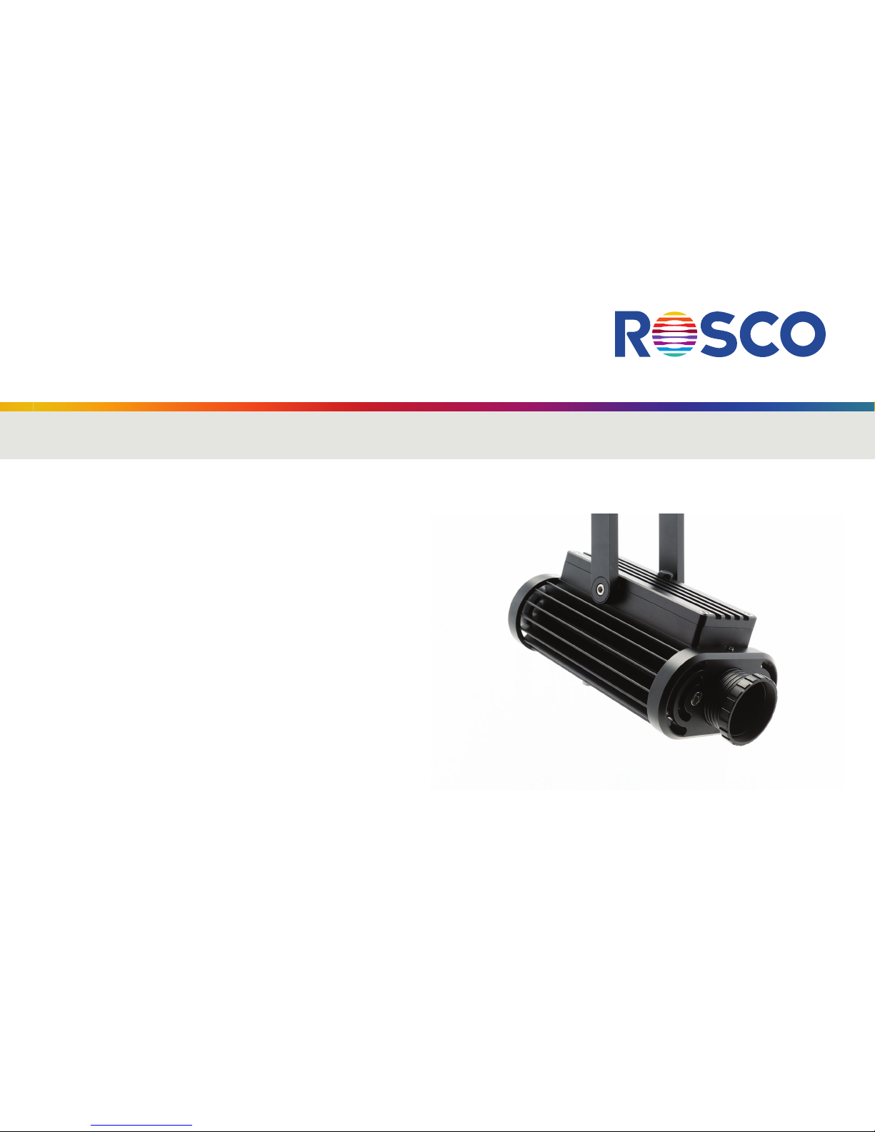
Image Spot™
This guide applies to the following Rosco Image Spot models:
Image Spot IP40
Black (296000040401)
White (296000040402)
Silver (296000040403)
Image Spot IP65
Black (296000040651)
White (2960 000 40652)
Silver (296000040653)
Image Spot IP65 w/ DMX Cable
Black (296000041651)
White (2960 000 41652)
Silver (296000041653)
Page 2

2
Page 3

3
TABLE OF CONTENTS
Introduction .................................................................................................................................................................4
Important Safeguards .............................................................................................................................................. 4
Unpacking .....................................................................................................................................................................7
Installing Lens Tube .................................................................................................................................................. 8
Wiring ............................................................................................................................................................................. 9
Mounting .................................................................................................................................................................... 10
Gobo Projection ...................................................................................................................................................... 11
Focusing ..................................................................................................................................................................... 12
Dimming Control ..................................................................................................................................................... 12
DMX Operation ....................................................................................................................................................... 13
Diffusion Filters ....................................................................................................................................................... 15
Dichroic Color Filters ............................................................................................................................................ 16
Accessories ................................................................................................................................................................ 17
Ordering Gobos & Permacolor Filters ...........................................................................................................18
Technical Specifications ....................................................................................................................................... 19
Warranty .................................................................................................................................................................... 20
Information and specifications in this document are subject to change without notice.
Rosco assumes no responsibility or liability for any errors or inaccuracies that may appear in this manual.
Image Spot™ Us er Guide Copyright ©2017 by Rosco
User Guide
Page 4
4
INTRODUCTION
Congratulations on your purchase of a Rosco Image Spot projector. Designed to provide crystal-clear imaging and
spot illumination, the Image Spot is quick and easy to set up with convenient on-board dimming or remote DMX
controls. Image Spot is available in durable indoor IP40 and outdoor IP65 versions. To ensure efficient and safe
operation, please take a few moments to read this manual completely.
IMPORTANT SAFEGUARDS
The symbols below are used throughout this manual to identify important safety information. Heed all warnings
and safety information.
Warning, Danger or Caution. Risk of Electric Shock.
Risk of severe electric shock.
Risk of personal injury.
Page 5

5
PREVENTING ELECTRIC SHOCK
This machine uses mains electrical power at 90-253VAC inclusive. When directly contacted, such voltages are
hazardous to human life. Follow all local electrical codes and take precautions when using this product.
This product is designed to operate from three-wire power systems, where one of the wires is a safety ground.
DO NOT disconnect the safety ground, or use extension cords or adapter plugs to connect this machine to a twowire system. Operation without a safety ground may result in hazardous electrical shock.
Use only extension cords that are of appropriate length and are rated for Image Spot’s specified voltage and
current. If an extension cord shows signs of wear or gets warm to the touch, discontinue its use and obtain a cord
with a higher current rating. Improper extension cords are hazardous and may result in poor performance due to
excessive voltage drop.
Disconnect unit from power source before servicing and when not in use.
Page 6

6
MAINTAINING SAFE OPERATION
Do not look directly into the Image Spot projector. Prolonged exposure to the light beam can cause damage to
eyesight.
Use only Rosco spare parts and accessories so as to not void the product warranty.
The Image Spot’s surface temperature can approach 150ºF (65ºC) during operation. Keep minimum 4 inches
(10cm) distance away from flammable materials / objects. Contact with the fixture during, or immediately
following, operation may result in burns.
Allow the unit to cool before attempting to service.
Rosco Image Spot must only be serviced by a qualified technician.
Rosco Image Spot is not certified for use in hazardous locations.
Rosco Image Spot is designed for operation within the range of 14° to 104°F (-10° to +40°C).
Ensure Rosco Image Spot is stored within the range of -4° to 140°F (-20° to +60°C).
Page 7

7
UNPACKING
Carefully remove the unit from the box.
Do not attempt to operate Rosco Image Spot projector if there are any signs of physical damage. In case of
damage, contact your local Rosco dealer.
Your Rosco Image Spot projector requires that an Image Spot focusing lens tube (purchased separately) be
inserted into the opening on the front of the unit prior to operation.
Three lens options are available, providing Narrow, Medium and Wide beam angles. The size of the image or the
beam angle can be adjusted by replacing the lens tube with an alternate size:
Item No. 296000100019 Narrow FL85 - 19º
Item No. 296000100025 Medium FL60 - 25º
Item No. 296000100030 Wide FL50 - 30º
Page 8

8
INSTALLING LENS TUBE
IP40 Units: Insert the small diameter end of the lens tube into the opening on the front of the projector.
IP65 Units: Slip the 2 provided O-rings onto the grooves on the back end of the lens tube. Gently insert the end
of the lens tube with O-rings into the opening on the front of the projector.
Page 9

9
WIRING
Your Rosco Image Spot projector will arrive with an unterminated power cord attached to the unit. Wiring to
an appropriate connector (not included with Image Spot purchase) or to line voltage should be performed by a
qualified electrician and is the responsibility of the installer or end user. The power cord wiring code is as follows:
Core No1: Live (Hot) Lead
Core No2: Neutral Lead
Green/Yellow: Ground
Ensure the correct power connections have been made to the Image Spot projector. The fixture will immediately
illuminate upon receiving power.
Page 10

10
MOUNTING
The Image Spot projector can be installed in the desired location via the center hole in the yoke. Adjust pan as
required. Adjust and fix the tilt of the projector via (1) the knurled thumb knob or (2) optional hex screw (supplied
with Image Spot) on the side of the yoke.
1 2
Page 11

11
GOBO PROJECTION
Prior to operating the Image Spot projector insert an Image Spot gobo into the gobo cassette located on the
underside of the fixture. Gobos with logos or other oriented graphics should be inserted upside down and
backwards for proper projection. Check to ensure the gobos are free of dust, fingerprints and other residue prior
to inserting the cassette into the accessory slot. Be sure to tighten the thumb screws on the gobo cassette after
re-inserting to maintain protection from dust and moisture. A flat tipped screw driver can be used for additional
torque to tighten the thumb screws. For optimum image quality, use Rosco Image Spot gobos, which feature
custom bezels that fit securely inside the Image Spot gobo cassette.
To avoid possible ingress of dirt and moisture, orient the Image Spot projector with the gobo cassette on the
underside of the unit.
Page 12

12
FOCUSING
Adjust the coarse focus of the unit by moving the lens tube inward/outward from the projector. The fine
focus can be adjusted by rotating the lens tube clockwise or counter-clockwise.
Due to the ultra-clear optics of the Image Spot projector, it is advised to keep the optic path clean of dust and
debris. Use a non-abrasive micro-fiber cloth with Rosco Lens Cleaner to clean the Image Spot lenses and any
glass gobos or Permacolor dichroic glass filters you may have installed.
DIMMING CONTROL
The Rosco Image Spot projector offers two modes of
control: Manual dimming operation or user-supplied
DMX512 data input.
In Manual mode the Image Spot projector beam
intensity can be adjusted using a flat tip screwdriver
(0.118”/3mm width). Insert the screwdriver into the
recessed dimming port located on the top of the
fixture towards the front. Turn the screw clockwise
for brighter output and counter-clockwise for dimmer
output.
Recessed dimming
port
Page 13

13
DMX OPERATION
A single channel is required for output intensity control via DMX. In order to set the DMX address, an optional
DMX Programming Cable (sold separately) is needed, as well as the free Image Spot Addressing Software that
can be downloaded at www.rosco.com/ImageSpot.
To set the DMX address on the Image Spot IP40 unit, you will need the USB to RJ45 Cable accessory, sold
separately. Plug the USB connector into the computer running the Image Spot Addressing Software, and the
RJ45 connector into the receiver on the rear panel of the fixture. Follow the prompts from the software to set
address (set value). The output of the unit can also be tested by entering a value between 255 (100%) and 1 (0%).
Page 14

14
DMX OPERATION
The Image Spot IP65 units can be ordered with a factory-installed 2m length of DMX cable that features a
water-proof gland. To set the fixture’s DMX address, you will need the Image Spot USB to RS485 Programming
Cable accessory (sold separately). Plug the USB connector into the computer running the Image Spot Addressing
Software and wire the cable’s multi-pin terminal block to the bare-ends of the fixture’s DMX cable using the
following terminal assignment:
o Terminal 1 Data + (Blue)
o Terminal 2 Data - (Orange)
o Terminal 3 Ground (White/Yellow)
1
2
3
When the fixture recognizes a valid DMX signal,
control of the unit will default to DMX. An
interruption of the DMX signal will cause the Image
Spot projector to revert to manual control, however
the last acquired output setting will be maintained.
Page 15

15
DIFFUSION FILTERS
An optional Image Spot OPTI-FLECS™ Filter Pack is available and features three pre-cut, 43mm round diffusion
filters that soften Image Spot’s beam for spot lighting purposes. The OPTI-FLECS Filter Pack includes:
•RetainingRing
•SoftDiffusion–43mmdia.
•SmoothingFrost–43mmdia.
•DoublePowderFrost–43mmdia.
To install OPTI-FLECS filters into the Image Spot: insert the 43mm disc into the front end of the lens tube and
then secure the filter into place using the Retaining Ring.
Page 16

16
DICHROIC COLOR FILTERS
Rosco Permacolor dichroic filters are available to provide fully customizable, long-term color options for your
Image Spot. For optimal performance and installation, specify Image Spot Permacolor Filters that feature custom
bezels to fit securely inside the Image Spot gobo cassette.
Install the Image Spot Permacolor Filter into the gobo cassette. The gobo cassette is deep enough to accept
both an Image Spot Gobo and an Image Spot Permacolor Filter. It is recommended that the Permacolor Filter
be installed on the “lamp-side” of the two. When properly installed, the order should be lamp -> Image Spot
Permacolor Filter -> Image Spot Gobo -> Lens Tube.
Page 17

17
ACCESSORIES
Item Number Description
296000010019 Image Spot Narrow Angle Lens Optic / 19º
296000010025 Image Spot Medium Angle Lens Optic / 25º
296000010030 Image Spot Wide Angle Lens Optic / 30º
296000010013 Image Spot OPTI-FLECS Filter Pack with Retaining Ring
296000010012 Image Spot Safety Cable, 3-ft (1m)
296000010011 Image Spot IP65 USB to RS485 Programming Cable
296000010017 Image Spot IP40 USB to RJ45 Programming Cable
Page 18

18
ORDERING GOBOS & PERMACOLOR FILTERS
Gobos and Permacolor Dichroic Filters for the Image Spot projector can be easily ordered through any Rosco
dealer. Visit www.rosco.com to locate the dealer nearest you and provide them with the information below.
Standard Gobos
XX XXX-SPOT Image Spot Standard Gobo, XXX XX = the five digit standard gobo number
Custom Gobos
2507210ISPOT Image Spot Custom Steel Gobo
260CUSBWOSPO Image Spot Custom B&W Glass Gobo
260CUS1COSPO Image Spot Custom One-Color Glass Gobo
260CUS2COSPO Image Spot Custom Two-Color Glass Gobo
260CUSMCOSPO Image Spot Custom Multi-Color Glass Gobo
Permacolor Dichroic Filters
1203-XXXX-SPOT Image Spot Permacolor Dichroic Glass Filter, XXXX = the four digit color number
For assistance ordering or specifying gobos or Permacolor filters for the Image Spot, please contact our Gobo
Customer Service Centers:
Americas Toll Free in the US: 866-228-2256 customgobo@rosco.com
Outside of the US: 512-388-5299
EMEA +44 (0)20 8659 2300 salesadmin@rosco.com
Page 19

19
TECHNICAL SPECIFICATIONS
Power
Input Voltage: Universal 100-230VAC+/-10%
Maximum Power
Consumption: 45W
Physical Charateristics
Dimensions: 7.8in. x 4.8in. x 3.2in.
(excluding yoke) (198mm x 121mm x 81mm)
Weight: 5.5 lbs. (2.5 kg)
LED Color Temperature = 5500K
3,000 lumen output
LM-79-08 : 50,000 hours @ 45C
Gobo Specifications Rosco Image Spot Gobo
with custom carrier
Working Environment
Ambient Temp.: Working temperature:
-10°C ~ 40°C (14°F ~104°F)
Humidity: 20 ~ 90% RH non-condensing
Data: DMX512–RJ45Connector
(IP40)
Optional Cat5e Cable (IP65)
Approvals: Conforms to UL STD # 62368-1 &
# 60950-22
Certified to CSA STDS C22.2
# 62368-1 & # 60950-22
Ratings: IP40 Indoor Use Only
IP65 Outdoor Use in Wet
Environments
Environmental: Disposal of Old Electrical &
Electronic Equipment
This symbol on the product or on
its packaging indicates that this
product shall not be treated as
household waste.
Page 20

20
3-YEAR LIMITED WARRANTY
Rosco Laboratories warrants to the first retail purchaser that this Product will be free from defects in
workmanship and material for a period of three years from the date of original purchase. For warranty service
you must be able to provide proof of purchase. Should this Product prove defective during the warranty period,
please contact your local Rosco office for Return Authorization. No warranty service will be performed without
Return Authorization. At Rosco’s sole discretion, covered Products will be repaired or replaced with new or
refurbished equipment or a model of like kind and quality. Exchanged or replaced parts and Products assume
the remaining warranty period of the original product covered by this limited warranty. You are responsible
for securely packaging the defective Product and returning it to Rosco as per the instructions of the Return
Authorization. Within North America, Rosco will ship the repaired or replaced Product to you freight prepaid.
Shipments to other locations will be made freight collect.
This warranty is non-transferable and does not extend beyond the first retail purchase of the Product.
This warranty does not cover damage to the Rosco Product caused by parts not manufactured, distributed or
certified by Rosco.
Rosco is not obligated to provide warranty service should the Product fail to be properly maintained or fail to
function properly as a result of misuse, abuse, improper installation, neglect, improper shipping, damage caused
by disasters such as flood, fire and lightning, improper electrical current or unauthorized service repairs other
than those by a Rosco Authorized Servicer.
If a claimed defect cannot be identified or reproduced, you will be held responsible for the costs incurred. Unless
otherwise stipulated by state law, all warranties expressed or implied are limited to the three (3) year period of
this warranty.
Page 21

21
THE WARRANTY AND REMEDY PROVIDED ABOVE ARE EXCLUSIVE AND IN LIEU OF ALL OTHER
EXPRESS OR IMPLIED WARRANT IES INCLUDING BUT NOT LIMITED TO THE IMPLIED WARRANTIES
OF MERCHANTABILITY, NON-INFRINGEMENT OR FITNESS FOR A PARTICULAR PURPOSE. EXCEPT AS
PROVIDED IN THIS WRITTEN WARRANTY AND UNLESS EXCLUSIONS ARE SPECIFICALLY FORBIDDEN BY
STATE LAW, NEITHER ROSCO NOR ITS AFFILIATES WILL BE LIABLE FOR ANY LOSS, INCONVENIENCE, OR
DAMAGE, INCLUDING DIRECT, SPECIAL, INCIDENTAL OR CONSEQUENTIAL DAMAGES, INCLUDING
INJURY TO PERSONS OR PROPERTY, RESULTING FROM THE USE OR INABILITY TO USE THE ROSCO
PRODUCT, WHETHER RESULTING FROM BREACH OF WARRANT Y OR ANY OTHER LEGAL THEORY.
Page 22

www.rosco.com/imagespot
5007481
 Loading...