

Page 1

LitePad Loop™
User’s Manual
Model 1008
Page 2

2
Page 3

Languages
English........................................................
Spanish....................................................
German.....................................................
French.......................................................
Japanese................................................
Italian....................................................
Pages 100 - 123
Pages 124 - 147
Pages 4 - 27
Pages 28 - 51
Pages 52 - 75
Pages 76 - 99
3
Page 4
Table of Contents - English
Your LitePad Loop™
A
B
C
D
E
In the Box........................................................
In the Pro Kit....................................................
Parts Diagram.............................................
Setting Up Your Loop
Attaching Loop to the Camera........................
Adjusting Loop Position...........................
Powering Up
Using AC Mains Power....................................
Using Battery Power.......................................
Dimming Control.............................................
Using Optional Accessories
AA Battery Holder............................................
Color Filters.....................................................
4” L-Bracket....................................................
8” Rods............................................................
Light Stand Plate.............................................
Safety Connections
Installing the Safety Thumb Screw..................
Attaching the Safety Cord..............................
5
6
7, 8
9
10, 11
12
13
13
14
15
16
17
18
19
20
4
G
Parts and Accessories List........................21, 22
Technical Data...................................................23
F
Support
Troubleshooting..............................................
CE...................................................................
RoHS..............................................................
Warranty.........................................................
24
25
26
27
Page 5
Your LitePad Loop
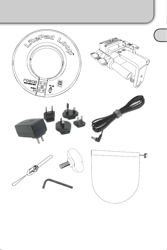
In the Box
A
[2]
[1]
[3]
[5]
[7]
[1] - LitePad Loop
[2] - Mounting Assembly
[3] - AC Transformer and Blades
[4] - 10’ Extension Cord
[6]
[4]
[8]
[5] - Safety Cord
[6] - Safety Thumb Screw
[7] - Allen Key
[8] - Storage Pouch
5
Page 6
Your LitePad Loop
A
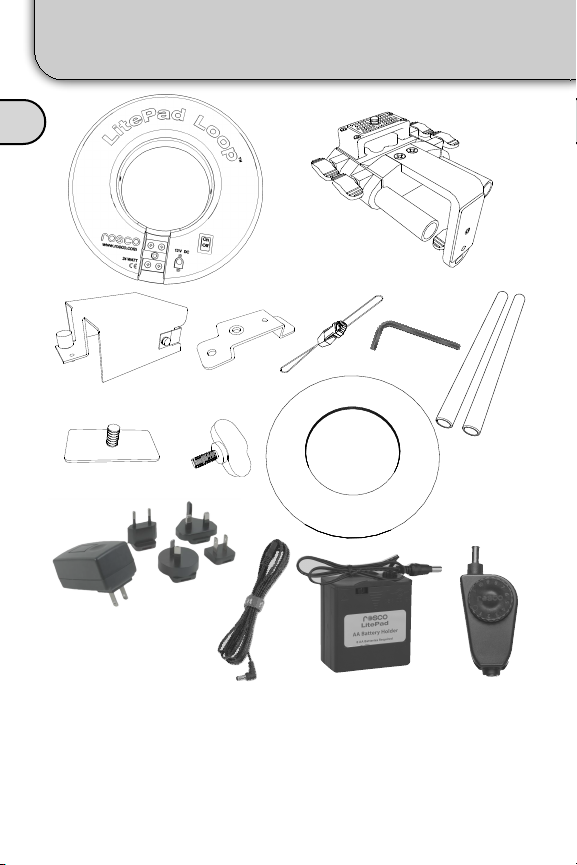
In the Pro Kit
[2]
[1]
[3]
[8]
[11]
[1] - LitePad Loop
[2] - Mounting Assembly
[3] - AA Battery Bracket
[4] - Battery Mounting Adapter
[5] - Safety Cord
[6] - Allen Key
[7] - 8” Rods
6
[9]
[4]
[12]
[5]
[8] - Light Stand Plate
[9] - Safety Thumb Screw
[10] - Color Filter Pack (8 Filters)
[11] - AC Transformer and Blades
[12] - 10’ Extension Cord
[13] - AA Battery Holder
[14] - Single Fader Dimmer
[6]
[13]
[7]
[10]
[14]
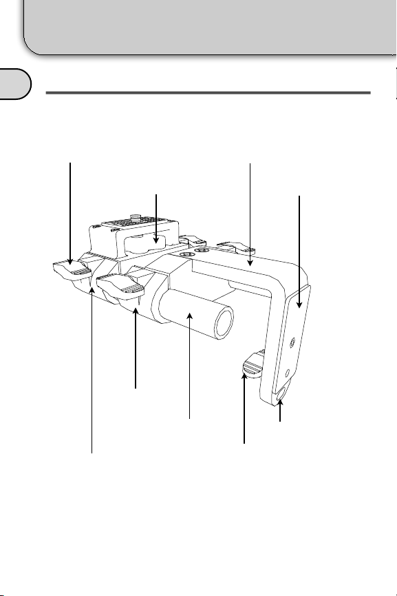
Page 7
Your LitePad Loop
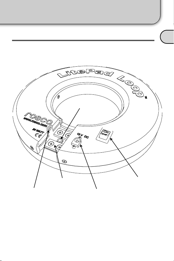
Parts Diagram
LITEPAD LOOP
Safety Screw
Nut [2]
Magnets [3] Power Switch [5]
Safety Cord Hole [1] Power Connector [4]
A
7
Page 8
Your LitePad Loop
LITEPAD MOUNTING ASSEMBLY
A
Thumb Screws [6] 2” L-Bracket [12]
Parts Diagram
Main Block [7]
8
Knob [11]
Sled [8]
(2) 4” Rods [9]
Mag. Plate
Wing Nut [10]
Mag. Plate [13]
Safety Cord Hole [14]
Page 9
Setting Up Your Loop
Attaching Loop to the Camera
1) Attach the Mounting Assembly to your camera by
screwing the Knob [11] into the threaded socket in the
bottom of the camera. Align the camera so the lens is
parallel with the L-Bracket [12]. Tighten the Knob to
ensure the camera will not move during use.
B
2) Attach the Loop to the L-Bracket [12] by bringing the
Magnets [3] into contact with the Magnet Plate [13].
9
Page 10
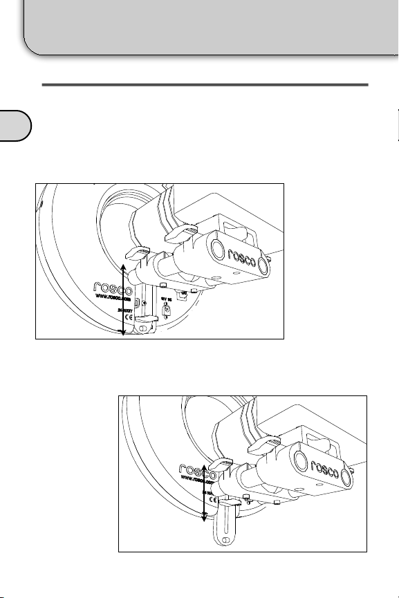
Setting Up Your Loop
Adjusting Loop Position
VERTICAL POSITION
The camera lens should be centered within the LitePad
Loop. To adjust the Loop vertically, loosen the Mag. Plate
B
Thumb Screw [10] and move the Loop up or down until
the camera lens is centered then tighten securely.
Loosen the thumb screw and slide the Loop up or down.
10
Center the camera lens vertically.
Page 11
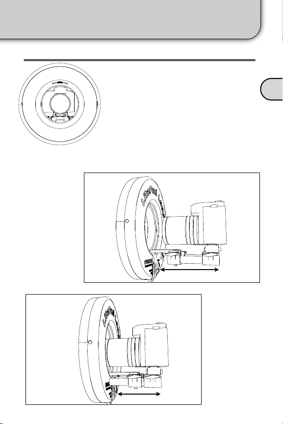
Setting Up Your Loop
FRONT/BACK POSITION
The camera lens should be positioned
just flush with the face of the LitePad
Loop. To adjust, loosen the the two
Sled [8] thumb screws and move the
entire Sled/Loop assembly until the
end of your lens is flush with the front
of the Loop. With longer lenses, it may
Centered LitePad Loop
be necessary to use the optional 4” LBracket and/or 8” Rods (page 16).
Loosen the thumb screws & slide the Loop forward and back.
Adjusting Loop Position
B
Slide the Loop so the front of the lens is flush with the Loop.
11
Page 12
Powering Up
Using AC Mains Power
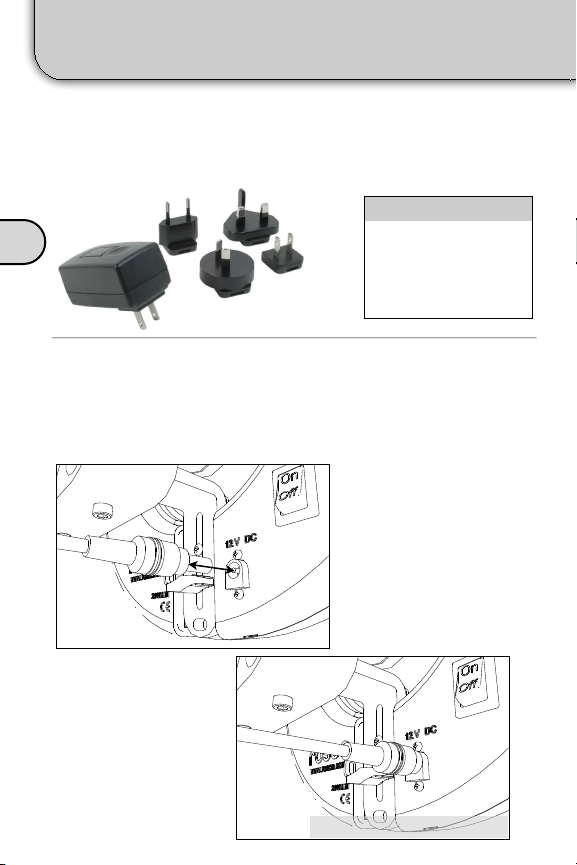
LitePad Loop comes with a multi-blade, 2.5Amp
Transformer. Select the blade style that is appropriate for
your locale and attach it to the transformer.
Blades Included
C
Insert the DC Barrel Connector of the transformer into the
power jack on the LitePad Loop as shown in Fig 11.1. You
can also use the right angle extension cable provided to
extend the transformer’s power cord. Next, plug the
North America
Australia
United Kingdom
Europe
transformer into an
appropriate mains power
outlet. An On/Off switch
next to the connector
powers the Loop on and
off.
Fig. 11.1
12
Power Cable Fully Connected.Fig. 11.2
Page 13
Powering Up
Using Battery Power & Dimming Control
USING BATTERY POWER
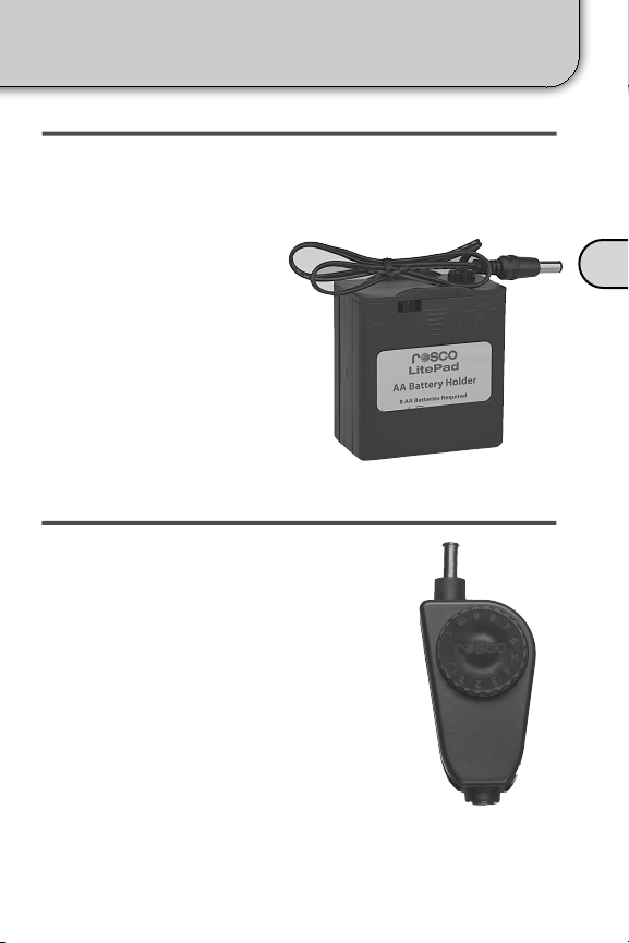
Optionally, LitePad Loop can be powered by any 12V DC
supply. Rosco offers several battery solutions including;
AA Battery Holder, Anton/Bauer, and V-Mount adapters.
The AA Battery Holder can
attach directly to the
bottom of the Loop
Mounting Assembly (see
page 14).
LitePad AA Battery Holder
DIMMING CONTROL
LitePad Loop can be dimmed using one
of Rosco’s LitePad dimmers. The Single
Fader Dimmer (Part: 290 64000 0012) will
allow for easy dimming in a compact
thumb wheel dimming system. The 2 CH/
DMX Dimmer (Part: 290 64100 0012) is a
two slide fader system that gives the user
control over two LitePads or two groups of
LitePads. The 2 CH/DMX Dimmer also
allows the LitePad Loop to be controlled
by computer lighting console via DMX 512
protocol. For more information,
please visit our website at
www.rosco.com.
C
Single Fader Dimmer
13
Page 14
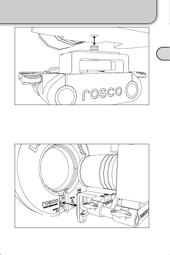
Using Optional Accessories
ATTACHING AA BATTERY HOLDER
To attach the optional AA
Battery Holder Bracket:
1. Unscrew the two cap
screws underneath the
Sled as show in Fig.
10.1.
D
2. Position the Battery
Mounting Adapter under
the sled as depicted in
Fig. 10.2 and fasten with
the two cap screws.
AA Battery Holder
Fig. 10.1
3. With the AA Battery
Holder already installed
in the AA Battery
Bracket, tighten the
thumb screw on the
Battery Bracket onto the
Battery Mounting
Adapter as shown in Fig.
10.3.
4. Plug the AA Battery
Holder power cord into
the LitePad Loop.
AA Battery Bracket
with AA Battery
Pack inside.
Battery Mounting
Adapter
NOTE: You must have the 4” L-Bracket to use the
Loop AA Battery Kit. See page 16.
14
Fig. 10.2
Fig. 10.3
Page 15
Using Optional Accessories
Color Filters
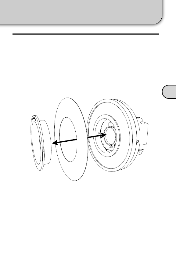
ATTACHING COLOR FILTERS
For more creative lighting options, Rosco offers the Color
Filter Pack designed to fit on the LitePad Loop. The Color
Filter Pack includes filters for warming the color temperature
(CTO Filters), Minusgreen, and Cosmetic filters, perfect for
enhancing flesh tones.
Ridged Gel LitePad Loop
Accessory
Collar
A simple magnetic collar makes it easy to attach color filters
to your LitePad Loop. Sandwich the Color Filter between the
Accessory Collar and the front of the LitePad Loop. The
Accessory Collar uses magnets to hold the color filter in
place. Turn the collar until the magnets align to securely hold
the Color Filter in place.
D
15
Page 16
Using Optional Accessories
4” L-Bracket
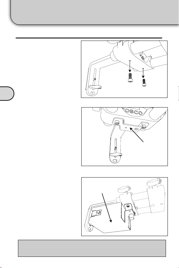
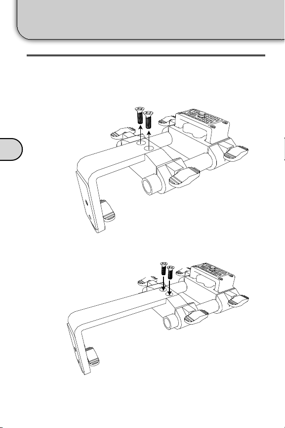
CHANGING THE L-BRACKET
If you should need to position the LitePad Loop further away
from the camera than the standard 2” L-Bracket allows, a
longer 4” L-Bracket is available. This is helpful for longer
lenses.
D
To change the L-Bracket, simply unscrew the two screws on
top of the Sled (Fig. 9.2).
Fig. 9.2
Fig. 9.3
Replace the 2” L-Bracket the 4” L-Bracket. Use the same
two screws to fasten the 4” L-Bracket to the Sled (Fig. 9.3).
16
Page 17
Using Optional Accessories
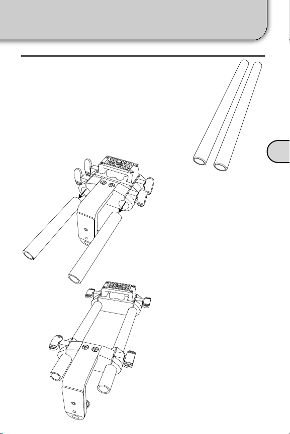
CHANGING TO 8” RODS
If it is necessary to extend the Sled further away
from the Main Block, longer 8” Rods are available.
Fig. 11.1
Fig. 11.2
1. Loosen the four thumb
screws on the Sled and
Main Block (two per
piece).
2. Slide the 4” Rods out of
the Sled and Main Block
as shown in Fig. 11.1.
3. Insert the 8” Rods into
the sleeves of both the
Sled and the Main Block
(shown in Fig. 11.2).
Adjust the Sled to the
desired position and
tighten the four thumb
screws.
8” Rods
D
8” Rods
17
Page 18
Using Optional Accessories
Light Stand Plate
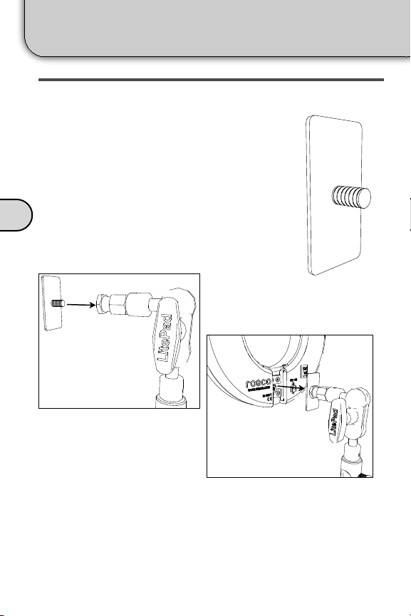
USING THE LIGHT STAND PLATE
Although the LitePad Loop has been designed primarily
for use on a camera, it may also be used as
an off camera light. To change the lighting
setup quickly, simply remove the Loop from
the Mounting Assembly and attach it via
magnets to the Light Stand Plate (in the Pro
Kit or sold separately). The Light Stand
Plate may then be mounted to the LitePad
Swivel Arm which can be further attached to
D
almost any light stand used in photo/video
production.
Fig. 18.1
Attaching the Stand Plate to the Swivel
Arm (sold separately)
Light Stand Plate
Fig. 18.2
Put the magnets on the Loop in contact
with the Stand Plate
To attach the LitePad Loop to a light stand, screw the Light
Stand Plate to the LitePad Swivel Arm (sold separately - see
page 23) - Fig. 18.1. The Swivel Arm can attach to a typical
light stand. Then put the flat side of the Stand Plate in contact
with the LitePad Loop magnets.
18
Page 19
Safety Connections
Installing the Safety Thumb Screw
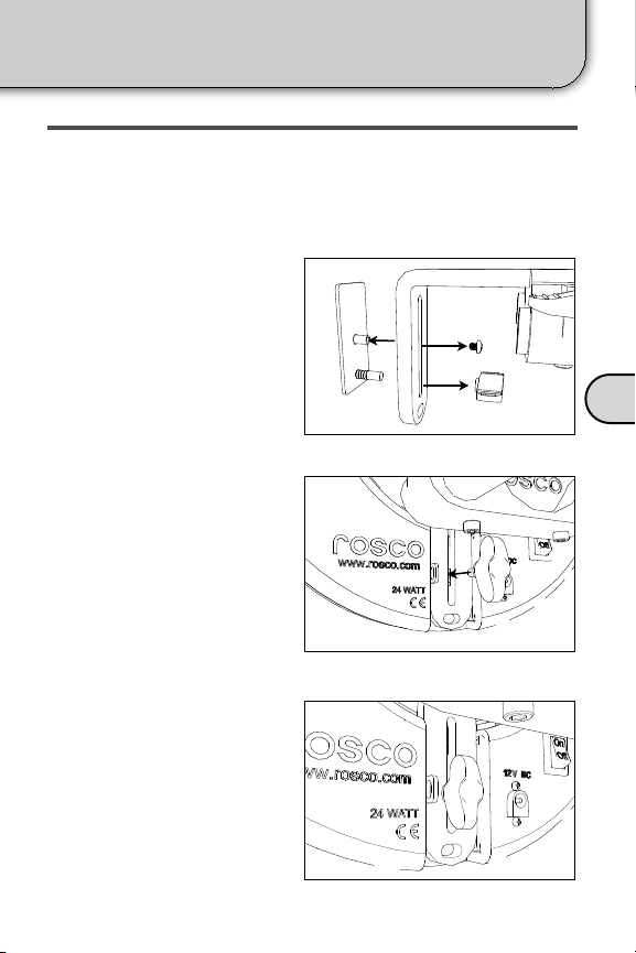
SAFETY THUMB SCREW
If you prefer a fixed attachment between the LitePad Loop and the
Mounting Assembly, the magnetic connection may be replaced by a
secure thumb screw - included with the Loop.
1. Unscrew and remove the
pan head screw and the
Wing Nut from the back of
the Mag. Plate as shown in
Fig. 12.1. Remove the Mag.
Plate and set it aside.
Fig. 12.1
2. Place the LitePad Loop
directly in contact with the
L-Bracket and screw the
provided Safety Thumb
Screw into the center hole
of the LitePad Loop Mag
Bracket. Fig. 12.2
Fig. 12.2
E
3. Slide the Loop up or down
to the desired position and
tighten the Safety Thumb
Screw. Fig. 12.3
Fig. 12.3
19
Page 20
Safety Connections
Attaching the Safety Cord
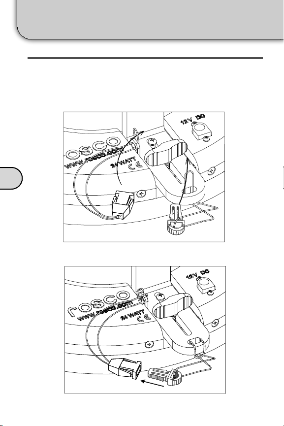
ATTACHING SAFETY CORD
A Safety Cord can be easily attached to the L-Bracket and
the LitePad Loop to provide additional security. It is
recommended that the safety cord be used at all times to
reduce incidents.
E
Fig. 12.4
Loop one safety cord through the LitePad Loop safety hole and
the other through the L-Bracket safety hole as shown in Fig. 12.4.
20
Fig. 12.5
Snap the buckles together - Fig. 12.5.
Page 21
Parts and Accessories List
Description
Item #
Thumb Screw Replacements - 4 Pack
291200021032
Anton/Bauer Bracket w/ Cheeseplate
291103050101
V-Mount Bracket w/ Cheeseplate
291103050102
LitePad Loop Color Pack
291200000008
LitePad Loop Light Masks
291200001009
8" Rods (pair)
291200030208
LitePad Loop AA Battery Kit
291636510812
LitePad Loop 4" L-Bracket Kit
291600010014
LitePad Loop Light Stand Plate
291600040002
Description
Item #
Single Fader Dimmer
290640000012
2 CH/DMX Dimmer
290641000012
Loop Accessories
F
Dimming
21
Page 22
Parts and Accessories List
Description
Item #
AA Battery Holder
290636510812
10ft Right Angle Ext. Cable
290637510000
Y Splitter
290637000000
Car Power Adapter
290636000000
4-Pin Power Adapter
290637700012
Anton/Bauer Power Adapter
290637900012
Description
Item #
LitePad Light Stand
290661049089
LitePad Snake Arm
290661142002
LitePad Swivel Arm
290661581420
LitePad Cold Shoe Attachment
290661001420
1/4 - 20 Baby (5/8) Pin
290639101420
Power Accessories
F
Position Hardware
22
Page 23
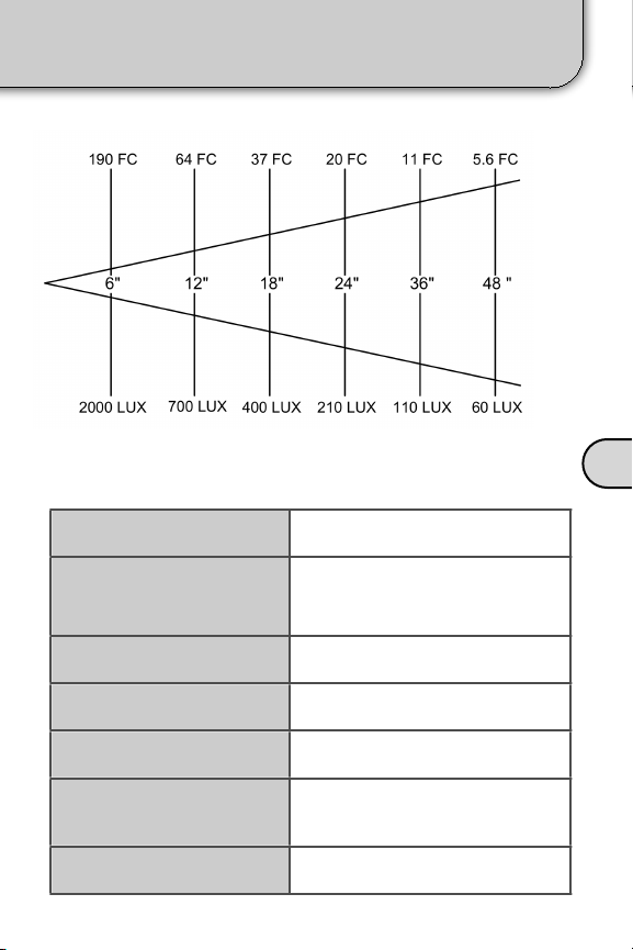
Power Consumption
24 Watts (2A at 12V DC)
Dimensions
9.1” (231mm) Diam.
1.3” (33mm) Depth
Weight
2.4 lbs (1.1kg)
Color Temperature
5,800ºK
Lamp Life
60,000 Hours
Operating Temperature
-22ºF - +185ºF
(-30ºC - +85ºC)
Power
12V DC Input
LitePad Loop Technical Data
Photometrics
Tech Data
F
23
Page 24
Rosco.
Support
Troubleshooting
My LitePad Loop won’t turn on.
Ensure that the transformer is firmly plugged in to a functional
power outlet and the DC power cable is firmly seated in the
LitePad Loop. Check that the On/Off switch is turned to On
position. If problem persists, contact Rosco.
I’ve lost one of my Thumb Screws.
Replacement screws are available in packs of four. Rosco
part number: 2912 0002 1032
My LitePad Loop moves when I turn my camera
sideways.
Retighten the knob screwed into the bottom of the camera. To
adjust Loop’s position, unscrew the knob, reposition the
camera and tighten the knob. If the problem persists, contact
I can’t get my LitePad Loop the correct distance
G
from my lens.
LitePad Loop comes standard with a 2” L-Bracket and 4”
Rods. To extend the Loop further than this combination
allows, optional 4” L-Bracket and/or 8” rods are available.
I want to change to color of my LitePad Loop.
Rosco offers a Color Filter Pack which includes color
correction and cosmetic filters. Rosco part number:
2912 0000 0008
If you problem cannot be solved by this manual, please contact a Rosco office.
Rosco Laboratories
www.rosco.com
Stamford, Glendale, London, Toronto, Madrid, São Paulo and Sydney
info@rosco.com
24
Page 25
DECLARATION OF CONFORMITY
ROSCO LABORATORIES INC.,
52 Harbor View Ave
Stamford, CT 06902
United States
Hereby declares that the product(s):
Rosco LitePad Loop™
Model Number(s)
1008
Conform(s) to the following Product Specifications:
European Council Directive 2004 / 108 / EC
EN 61326-1:2006, EN 61000-3-2:2006, EN 61000-3-3, 1995+A1:2001+A2:2005
European Council Directive 2006 / 95 / EC
EN 61010-1:2001
Joshua Alemany
Director of Products
Date: March 1, 2012
Support
CE Certification
G
25
Page 26

Rosco Laboratories Inc.
52 Harbor View Ave
Stamford, CT 06902
TEL: +1 203 708 8900
FAX: +1 203 708 8919
EMAIL: info@rosco.com
WEB: www.rosco.com
Declaration of Compliance
This serves to confirm that we, Rosco Laboratories Inc., declare in regard to the
European Union Directives listed below that our products, namely:
1. LitePad Loop™
do comply with the requirements set forth in:
•
EU Directive 2002/95/EC on the restriction of the use of certain hazardous
substances in electrical and electronic equipment (called RoHS-Directive).
•
EU Directive 2002/96/EC on waste electrical and electronic equipment (called
WEEE-Directive).
•
EU Directive 2003/11/EC, amending for the 24th time Council Directive 76/769/
EEC, relating to restrictions on the marketing and use of certain dangerous
substances and preparations (pentabromodiphenyl ether, octabromodiphenyl
ether).
•
Compounds of cadmium lead, mercury and hexavalent chromium, flame
retardants PBB and PBDE included pentabromodiphenyl ether (CAS-No.
32534-81-9 and octabromodiphenyl ether (CAS-No. 32536-52-0), have not been
intentionally added during the manufacturing process. In the event that trace
amounts of any of these chemicals are present, we would not expect the total of
these materials to exceed the allowable tolerance levels.
Further, we declare that we have processes and systems in place to ensure
continued compliance with the RoHS directive.
If you have any questions, please contact the undersigned.
Joshua Alemany
Director of Product Marketing
Date Signed: 3/1/12
Support
RoHS Certification
G
26
Page 27

Support
Warranty
LIMITED WARRANTY AND DISCLAIMER
(a)!Rosco warrants that, under normal use in accordance with the applicable user manual, the
Products shall, at the time of delivery to Buyer and for a period of twenty-four (24) months
from the date of delivery (or such other period as may be agreed upon in writing by the
parties), be free from defects in material or workmanship and shall substantially conform to
Rosco’ specifications for such Product, or such other specifications as Rosco has agreed to in
writing, as applicable. Rosco’ sole and exclusive obligation, and Buyer’s sole and exclusive
right, with respect to claims under this warranty shall be limited, at Rosco’ option, either to the
replacement or repair of a defective or non-conforming Product or to an appropriate credit for
the purchase price thereof. Rosco will have a reasonable time to repair, replace or credit. The
non-conforming or defective Products shall become Rosco' property as soon as they have
been replaced or credited.! At Rosco’s sole discretion, any replacement products may be new
or like-new and may contain remanufactured parts, equivalent to new in performance
(b)!Rosco reserves the right to choose all contractors and/or consultants in connection with
validation and rectification of a product complaint. If it is subsequently determined that Rosco
or it products are not responsible for an alleged product failure, it is agreed the costs of such
contractors and/or consultants and any rectification costs incurred will be repaid to Rosco.
(c)! Buyer may ship Products returned under warranty to Rosco’ designated facility only in
conformance with Rosco’ then-current return material authorization policy. Where a warranty
claim is justified, Rosco will pay for freight expenses. Buyer shall pay for returned Products
that are not found to be defective or non-conforming together with the freight, testing and
handling costs associated therewith.
(d)! Notwithstanding the foregoing, Rosco shall have no obligations under warranty if the
alleged defect or non-conformance is found to have occurred as a result of environmental or
stress testing, misuse, use other than as set forth in the user manual, neglect, use of a nonapproved power supply, use of non-approved dimming accessories, improper installation or
accident, or as a result of improper repair, alteration, modification, storage, transportation or
improper handling.
(e)! The express warranty granted above shall extend directly to Buyer and not to Buyer’s
customers, agents or representatives and is in lieu of all other warranties, whether express or
implied, including without limitation any implied warranties of fitness for a particular purpose,
merchantability, or non-infringement of intellectual property rights. All other warranties are
hereby specifically disclaimed by Rosco.
(f)!Subject to the exclusions and limitations set forth in Section 9 of the Terms and Conditions,
the foregoing states the entire liability of Rosco in connection with defective or nonconforming Products supplied hereunder.
!
LIMITATION OF LIABILITY
(a)! ROSCO SHALL NOT BE LIABLE FOR ANY LOST PROFITS, INSTALLATION OR REINSTALLATION COSTS, LOST SAVINGS, LOSS OF REPUTATION, LOSS OF GOODWILL,
INDIRECT, INCIDENTAL, PUNITIVE, SPECIAL OR CONSEQUENTIAL DAMAGES ARISING
OUT OF OR IN CONNECTION WITH THE AGREEMENT OR THE SALE OF ANY
PRODUCTS OR SERVICES BY ROSCO OR THE USE THEREOF WHETHER OR NOT
SUCH DAMAGES ARE BASED ON TORT, WARRANTY, CONTRACT OR ANY OTHER
LEGAL THEORY – EVEN IF ROSCO HAS BEEN ADVISED, OR IS AWARE, OF THE
POSSIBILITY OF SUCH DAMAGES.
ROSCO’ AGGREGATE AND CUMULATIVE LIABILITY TOWARDS BUYER UNDER ANY
AGREEMENT SHALL NOT EXCEED AN AMOUNT OF TEN PERCENT (10%) OF THE
RELATED AGREEMENT.
(b)!Any Buyer’s claim for damages must be brought by Buyer within ninety (90) days of the
date of the event giving rise to any such claim, and any lawsuit relative to any such claim
must be filed within one (1) year of the date of the claim. Any claims that have been brought
or filed not in accordance with the preceding sentence are null and void.
(c) The limitations and exclusions set forth above in this Section shall apply only to the
extent permitted by applicable mandatory law.
G
27
Page 28

Índice - Español
Su LitePad Loop™
A
B
C
D
E
Contenido de la Caja........................................
En el Pro Kit.....................................................
Diagrama de Piezas...................................
Configuración del Loop
Fijación del Loop a la Cámara..........................
Ajuste de la Posición del Loop...................
Encendido
Utilización de la Alimentación de CA.................
Utilización de la Alimentación con Baterías.......
Control de Atenuación.......................................
Utilización de Accesorios Opcionales
AA Battery Holder..............................................
Filtros de Color...................................................
4” L-Bracket.......................................................
8” Rods..............................................................
Light Stand Plate................................................
Conexiones de Seguridad
Instalación del Safety Thumb Screw..................
Fijación de la Cuerda de Seguridad..................
29
30
31, 32
33
34, 35
36
37
37
38
39
40
41
42
43
44
F
G
28
Lista de piezas y accesorios......................45, 46
Datos Técnicos..................................................47
Soporte
Solución de Problemas......................................
CE......................................................................
RoHS.................................................................
Garantía.............................................................
48
49
50
51
Page 29

Su LitePad Loop
Contenido de la Caja
A
[2]
[1]
[3]
[5]
[7]
[1] - LitePad Loop
[2] - Conjunto de montaje
[3] - Transformador de CA y Espigas
[4] - 10’ Extension Cord
[6]
[4]
[8]
[5] - Cuerda de Seguridad
[6] - Tornillo de pulgar de seguridad
[7] - Llave Allen
[8] - Maleta de Transportación
29
Page 30

Su LitePad Loop
A
En el Pro Kit
[2]
[1]
[3]
[8]
[11]
[1] - LitePad Loop
[2] - Conjunto de montaje
[3] - AA Battery Bracket
[4] - Battery Mounting Adapter
[5] - Cuerda de Seguridad
[6] - Llave Allen
[7] - 8” Rods
30
[9]
[4]
[12]
[5]
[8] - Light Stand Plate
[9] - Tornillo de pulgar de seguridad
[10] - Color Filter Pack (8 filtros)
[11] - Transformador de CA y Espigas
[12] - 10’ Extension Cord
[13] - AA Battery Holder
[14] - Single Fader Dimmer
[6]
[13]
[7]
[10]
[14]
Page 31

Su LitePad Loop
Diagrama de Piezas
LITEPAD LOOP
Imanes [3]
Agujero para la Cuerda
de Seguridad [1]
A
Seguridad
Tuerca [2]
Interruptor de
Encendido [5]
Conector de
Alimentación [4]
31
Page 32

Su LitePad Loop
CONJUNTO DE MONTAJE DEL LITEPAD
A
Tornillos de
Pulgar[6] 2” L-Bracket [12]
Diagrama de Piezas
32
Trineo [8]
Bloque
principal [7]
Perilla [11]
(2) 4” Rods [9]
Placa magnética
[13]
Agujero para la
Cuerda de
Seguridad [14]
Tuerca de mariposa
de la placa
magnética [10]
Page 33

Configuración del Loop
Fijación del Loop a la Cámara
1) Fije el conjunto de montaje a su cámara enroscando
la Perilla [11] en el receptáculo roscado de la parte
inferior de la cámara. Alinee la cámara de manera que el
lente esté paralelo al Soporte en L [12]. Apriete la perilla
para asegurar que la cámara no se mueva durante el
uso.
B
2) Fije el Loop al Soporte en L [12] poniendo los Imanes
[3] en contacto con la Placa magnética [13].
33
Page 34

Configuración del Loop
Ajuste de la Posición del Loop
POSICIÓN VERTICAL
El lente de la cámara debe estar centrado dentro del
LitePad Loop. Para ajustar verticalmente el Loop, afloje el
B
Tornillo de pulgar [10] de la placa magnética y mueva el
Loop hacia arriba o hacia abajo hasta que el lente de la
cámara esté centrado, entonces apriételo fuertemente.
Afloje el tornillo de pulgar y deslice el Loop hacia arriba o
hacia abajo.
Centre el lente de la cámara verticalmente.
34
Page 35

Configuración del Loop
Ajuste de la Posición del Loop
POSICIÓN DELANTERA/TRASERA
El lente de la cámara debe posicionarse justo
al ras con la cara del LitePad Loop. Para
ajustarlo, afloje los dos tornillos de pulgar
del Sled [8] y mueva todo el conjunto Sled/
Loop hasta que el extremo del lente esté al
ras con el frente del Loop. Con lentes más
largos, es posible que sea necesario utilizar
el 4” L-Bracket y/o las 8” Rods opcionales.
LitePad Loop Centrado
B
Afloje los tornillos de pulgar y deslice el Loop hacia atrás
Deslice el Loop de forma tal que la parte delantera del lente
esté al ras con el Loop.
y hacia adelante.
35
Page 36

Encendido
Utilización de la Alimentación de CA
El LitePad Loop viene con un transformador de 2,5 A de
múltiples espigas. Seleccione el tipo de espigas
apropiado para su región y conéctelas al transformador.
Espigas Incluidas
C
Inserte el DC Barrel Connector del transformador en el
conector de alimentación del LitePad Loop como se muestra
en la Fig. 11.1. También puede utilizar el Right Angle
Extension cable que se proporciona para extender el cable
Fig. 11.1
América del Norte
Australia
Reino Unido
Europa
de alimentación del
transformador. A
continuación, conecte el
transformador en una
toma de corriente
apropiada. Un interruptor
colocado cerca del
conector permite
encender y apagar el
Loop.
36
Fig. 11.2
Cable de alimentación totalmente
conectado.
Page 37

Encendido
Utilización de la Alimentación con Batería y del Control de Atenuación
UTILIZACIÓN DE LA ALIMENTACIÓN CON BATERÍAS
De manera opcional, el LitePad Loop puede alimentarse
por cualquier fuente de 12 VCC. Rosco ofrece varias
soluciones de baterías que incluyen: adaptadores AA
Battery Holder, Anton/
Bauer, and V-Mount.
El AA Battery Holder se
puede fijar directamente a
la parte inferior del Loop
Mounting Assembly
(consulte la página 38).
LitePad AA Battery Holder
CONTROL DE ATENUACIÓN
El LitePad Loop puede atenuarse utilizando
uno de los dimmers LitePad de Rosco. El
Single Fader Dimmer (No. de pieza: 290
64000 0012) permitirá una fácil atenuación
mediante un sistema compacto de rueda
selectora. El 2 CH/DMX Dimmer (No. de
pieza: 290 64100 0012) es un sistema
atenuador de dos controles deslizantes que
le permite al usuario controlar dos LitePads
o dos grupos de LitePads. El 2 CH/DMX
Dimmer también permite que el LitePad
Loop se controle mediante una consola
de iluminación por ordenador a través
del protocolo DMX 512. Para más información visite nuestro
sitio Web www.rosco.com.
Single Fader Dimmer
C
37
Page 38

Utilización de Accesorios Opcionales
AA Battery Holder
FIJACIÓN DEL AA BATTERY HOLDER
Para fijar el AA Battery
Holder Bracket opcional:
1. Desenrosque los dos
tornillos con cabeza que
están debajo del Trineo
como se muestra en la
Fig. 10.1.
D
2. Posicione el Battery
Mounting Adapter bajo
el Sled como se
muestra en la Fig. 10.2
Y apriételo con los dos
tornillos con cabeza.
Fig. 10.1
3. Con el AA Battery
Holder ya instalado en
el AA Battery BracketA,
apriete el tornillo de
pulgar del Battery
Bracket al Battery
Mounting Adapter como
se muestra en la Fig.
10.3.
4. Conecte el cable de
alimentación del AA
Battery Holder al
LitePad Loop.
AA Battery Bracket
con el AA Battery
Pack dentro.
Battery Mounting
Adapter
NOTA: Debe tener el 4” L-Bracket para usar el Loop AA
Battery Kit. Consulte la página 40.
38
Fig. 10.2
Fig. 10.3
Page 39

Utilización de Accesorios Opcionales
Filtros de Color
COLOCACIÓN DE LOS FILTROS DE COLOR
Para opciones de iluminación más creativas, Rosco ofrece el
Color Filter Pack de Color diseñados para colocarse en el
LitePad Loop. El Color Filter Pack incluye filtros para la
elevación de la temperatura de color (filtros CTO), filtros
Minusgreen y Cosmetic, perfectos para mejorar los tonos de
la carne.
Gel Ondulado LitePad Loop
Accessory
Collar
Un sencillo collar magnético facilita la colocación de los
filtros de color en el LitePad Loop. Inserte el Filtro de Color
entre el Accessory Collar y el frente del LitePad Loop. El
Accessory Collar utiliza imanes para sostener en su lugar el
filtro de color. Gire el collar hasta que los imanes se alineen
para sostener firmemente en su lugar el filtro de color.
D
39
Page 40

Utilización de Accesorios Opcionales
4” L-Bracket
CAMBIO DEL SOPORTE EN L
Si necesitara colocar el LitePad Loop más alejado de la
cámara que lo que permite el 2” L-Bracket estándar, está
disponible un 4” L-Bracket más largo. Esto es útil para
lentes más largos.
D
Para cambiar el Soporte en L, simplemente desenrosque los
dos tornillos de la parte superior del Trineo (Fig. 9.2).
Fig. 9.2
Fig. 9.3
Sustitución del 2” L-Bracket por el 4” L-Bracket. Use los
mismos dos tornillos para fijar el 4” L-Bracket al Sled (Fig.
9.3).
40
Page 41

Utilización de Accesorios Opcionales
8” Rods
CAMBIO A LAS 8" RODS
Si es necesario alejar más aún el Sled del Main
Block, están disponibles 8" Rods más largas.
Fig. 11.1
Fig. 11.2
1. Afloje los cuatro tornillos
de pulgar del Sled y del
Main Block (dos por
pieza).
2. Deslice las 4" Rods
fuera del Sled y del
Main Block como se
muestra en la Fig. 11.1.
3. Inserte las 8" Rods en
los manguitos del Sled y
del Main Block
(mostrados en la Fig.
11.2). Ajuste el Sled en
la posición deseada y
apriete los cuatro
tornillos de pulgar.
D
8” Rods
41
Page 42

Utilización de Accesorios Opcionales
UTILIZACIÓN DE LA LIGHT STAND PLATE
Light Stand Plate
Aunque el LitePad Loop se ha diseñado para utilizarlo
principalmente en una cámara, también puede
usarse como una luz separada de la cámara.
Para cambiar rápidamente la configuración de
la iluminación, simplemente retire el Loop del
Mounting Assembly y fíjelo mediante los imanes
a la Light Stand Plate (en el Kit Pro o vendido
por separado). La Stand Plate de la Luz puede
entonces montarse en el LitePad Swivel Arm el
D
cual puede a su vez puede fijarse a casi
cualquier soporte de luz utilizado en la
producción de fotos y vídeos.
Fig. 18.1
Fijación de la Stand Plate al Swivel Arm
(vendido por separado)
Light Stand Plate
Fig. 18.2
Ponga los imanes del Loop en contacto
con la Stand Plate
Para fijar el LitePad Loop a un soporte de luz, enrosque la Light
Stand Plate al LitePad Swivel Arm (vendido por separado;
consulte la página 23) - Fig. 18.1. El Swivel Arm puede fijarse a
un soporte de luz típico. Entonces ponga el lado plano de la
Stand Plate en contacto con los imanes del LitePad Loop.
42
Page 43

Conexiones de Seguridad
Instalación del Tornillo de Pulgar de Seguridad
SAFETY THUMB SCREW
Si prefiere una conexión fija entre el LitePad Loop y el
Mounting Assembly, la fijación magnética puede sustituirse
por un Safety Thumb Screw incluido con el Loop.
1. Desenrosque y retire el
tornillo de cabeza alomada
y la Wing Nut de la parte
trasera de la Mag. Plate,
como se muestra en la Fig.
12.1. Retire la Mag. Plate y
póngala a un lado.
Fig. 12.1
2. Coloque el LitePad Loop
directamente en contacto
con el L Bracket y enrosque
el Safety Thumb Screw
proporcionado en el
agujero central del Soporte
Magnético del LitePad
Loop. Fig. 12.2
Fig. 12.2
E
3. Deslice el Loop hacia arriba
y hacia abajo hasta la
posición deseada y apriete
el Safety Thumb Screw.
Fig. 12.3
Fig. 12.3
43
Page 44

Conexiones de Seguridad
Fijación de la Cuerda de Seguridad
FIJACIÓN DE LA CUERDA DE SEGURIDAD
Se puede fijar con facilidad una Cuerda de Seguridad al L Bracket y
al LitePad Loop para proporcionar seguridad adicional. Se
recomienda utilizar en todo momento la cuerda de seguridad para
reducir la posibilidad de incidentes.
E
Fig. 12.4
Introduzca un extremo de la cuerda de seguridad a través del
agujero de seguridad del LitePad Loop y el otro a través del agujero
de seguridad del L Bracket, como se muestra en la Fig. 12.4.
44
Fig. 12.5
Una a presión las hebillas – Fig. 12.5.
Page 45

Lista de Piezas y Accesorios
Descripción
No. de Artículo
Thumb Screw Replacements - 4 Pack
291200021032
Anton/Bauer Bracket w/ Cheeseplate
291103050101
V-Mount Bracket w/ Cheeseplate
291103050102
LitePad Loop Color Pack
291200000008
LitePad Loop Light Masks
291200001009
8" Rods (pair)
291200030208
LitePad Loop AA Battery Kit
291636510812
LitePad Loop 4" L-Bracket Kit
291600010014
LitePad Loop Light Stand Plate
291600040002
Descripción
No. de Artículo
Single Fader Dimmer
290640000012
2 CH/DMX Dimmer
290641000012
Accesorios del Loop
F
Atenuación
45
Page 46

Lista de Piezas y Accesorios
Descripción
No. de Artículo
AA Battery Holder
290636510812
10ft Right Angle Ext. Cable
290637510000
Y Splitter
290637000000
Car Power Adapter
290636000000
4-Pin Power Adapter
290637700012
Anton/Bauer Power Adapter
290637900012
Descripción
No. de Artículo
LitePad Light Stand
290661049089
LitePad Snake Arm
290661142002
LitePad Swivel Arm
290661581420
LitePad Cold Shoe Attachment
290661001420
1/4 - 20 Baby (5/8) Pin
290639101420
Accesorios de Alimentación
F
Accesorios de Posicionamiento
46
Page 47

Datos Técnicos del LitePad Loop
Consumo de Potencia
24 Watts (2A at 12V DC)
Dimensiones
9.1” (231mm) Diám.
1.3” (33mm) de Profundidad
Peso
2.4 lbs (1.1kg)
Temperatura de Color
5,800ºK
Vida útil de la Lámpara
60,000 Horas
Temperatura de
Funcionamiento
-22ºF - +185ºF
(-30ºC - +85ºC)
Alimentación
Entrada de 12V DC
Fotometría
Datos Técnicos
F
47
Page 48

Soporte
problema persiste, contacte con Rosco.
Solución de Problemas
El LitePad Loop no se enciende.
Asegúrese de que el transformador esté bien conectado en una toma
de corriente con alimentación y que el cable de alimentación de CC
esté correctamente introducido en el LitePad Loop. Compruebe que
el Interruptor de Encender/Apagar esté en la posición On (Encender).
Si el problema persiste, contacte con Rosco.
He perdido uno de mis Tornillos de Pulgar.
Están disponibles tornillos de repuesto en paquetes de
cuatro. Número de la pieza de Rosco: 2912 0002 1032
El LitePad Loop se mueve cuando giro mi cámara
lateralmente.
Apriete de nuevo la Knob enroscada en la parte inferior de la
cámara. Para ajustar la posición del Loop, desenrosque la
Knob, posicione de nuevo la cámara y apriete la Knob. Si el
No puedo obtener la distancia correcta entre el
G
LitePad Loop y el lente.
El LitePad Loop viene estándar con un L Bracket de 2 " y 4"
Rods. Para extender el Loop más allá de lo que permite esta
combinación, están disponibles 4” L-Bracket y/o 8" Rods
opcionales.
Quiero cambiar el color de mi LitePad Loop.
Rosco ofrece un Color Filter Pack que incluye correcciones
de color y filtros cosméticos. Número de la pieza de Rosco:
2912 0000 0008
Si no puede resolver su problema con este manual, contacte con una oficina de Rosco.
Rosco Laboratories
www.rosco.com
Stamford, Glendale, London, Toronto, Madrid, São Paulo and Sydney
info@rosco.com
48
Page 49

Soporte
DECLARATION OF CONFORMITY
ROSCO LABORATORIES INC.,
52 Harbor View Ave
Stamford, CT 06902
United States
Hereby declares that the product(s):
Rosco LitePad Loop™
Model Number(s)
1008
Conform(s) to the following Product Specifications:
European Council Directive 2004 / 108 / EC
EN 61326-1:2006, EN 61000-3-2:2006, EN 61000-3-3, 1995+A1:2001+A2:2005
European Council Directive 2006 / 95 / EC
EN 61010-1:2001
Joshua Alemany
Director of Products
Date: March 1, 2012
Certificación CE
G
49
Page 50

Rosco Laboratories Inc.
52 Harbor View Ave
Stamford, CT 06902
TEL: +1 203 708 8900
FAX: +1 203 708 8919
EMAIL: info@rosco.com
WEB: www.rosco.com
Declaration of Compliance
This serves to confirm that we, Rosco Laboratories Inc., declare in regard to the
European Union Directives listed below that our products, namely:
1. LitePad Loop™
do comply with the requirements set forth in:
•
EU Directive 2002/95/EC on the restriction of the use of certain hazardous
substances in electrical and electronic equipment (called RoHS-Directive).
•
EU Directive 2002/96/EC on waste electrical and electronic equipment (called
WEEE-Directive).
•
EU Directive 2003/11/EC, amending for the 24th time Council Directive 76/769/
EEC, relating to restrictions on the marketing and use of certain dangerous
substances and preparations (pentabromodiphenyl ether, octabromodiphenyl
ether).
•
Compounds of cadmium lead, mercury and hexavalent chromium, flame
retardants PBB and PBDE included pentabromodiphenyl ether (CAS-No.
32534-81-9 and octabromodiphenyl ether (CAS-No. 32536-52-0), have not been
intentionally added during the manufacturing process. In the event that trace
amounts of any of these chemicals are present, we would not expect the total of
these materials to exceed the allowable tolerance levels.
Further, we declare that we have processes and systems in place to ensure
continued compliance with the RoHS directive.
If you have any questions, please contact the undersigned.
Joshua Alemany
Director of Product Marketing
Date Signed: 3/1/12
Soporte
Certificación RoHS
G
50
Page 51

Soporte
Garantía
GARANTÍA LIMITADA Y EXENCIÓN DE RESPONSABILIDAD
(a) Rosco garantiza que, bajo condiciones normales de uso y de acuerdo con lo indicado en el
manual de usuario aplicable, los Productos, en el momento de su entrega al Comprador y
durante un período de veinticuatro (24) meses a partir de la fecha de la entrega (u otro período
que pueda acordarse por escrito entre las partes), estarán libres de defectos en materiales o
mano de obra y que cumplirán sustancialmente con las especificaciones de Rosco para dichos
Productos, o con otras especificaciones que Rosco haya aceptado por escrito, según sea
aplicable. La única y exclusiva obligación de Rosco y el único y exclusivo derecho del
Comprador, con respecto a las reclamaciones amparadas por esta garantía, estarán limitadas,
a la opción de Rosco, a la sustitución o reparación de un Producto defectuoso o no conforme o
a un crédito apropiado por el precio de compra del mismo. Rosco tendrá un tiempo razonable
para reparar, sustituir u otorgar el crédito. Los Productos no conformes o defectuosos pasarán
a ser propiedad de Rosco tan pronto se sustituyan o se otorgue el crédito. A la única discreción
de Rosco, cualesquiera productos de sustitución pueden ser nuevos o como si fueran nuevos
y pueden contener piezas reacondicionadas, equivalentes a las nuevas en su desempeño.
(b) Rosco se reserve el derecho de seleccionar todos los contratistas y o consultores en
relación con la validación y rectificación de una queja sobre un producto. Si se determina
subsiguientemente que Rosco o sus productos no son los responsables de la supuesta falla de
un producto, se acepta que los costos de dichos contratistas y/o consultores, así como los
costos de cualquier rectificación en que incurran, se le reembolsarán a Rosco.
(c) El comprador puede enviar los Productos devueltos bajo garantía a la instalación
designada de Rosco solamente de conformidad con la política de Rosco para la autorización
de devolución de materiales vigente en ese momento. Cuando una reclamación por garantía
sea justificada, Rosco pagará los gastos del flete. El Comprador pagará por el envío de los
Productos devueltos que se determine que no estén defectuosos ni que sean no conformes
junto con el flete, las pruebas y los costos de manipulación asociados con ellos.
(d) A pesar de lo anterior, Rosco no tendrá obligaciones bajo la garantía si el defecto o la no
conformidad supuestos se determina que ocurrieron como resultado de pruebas
medioambientales o de estrés, mal uso, usos diferentes a los establecidos en este manual de
usuario, negligencia, uso de una fuente de alimentación no aprobada, uso de accesorios de
atenuación no aprobados, instalación inadecuada o accidente, o de reparaciones, alteraciones,
modificaciones, almacenamiento, transportación o manipulación inadecuados.
(e) La garantía expresa otorgada anteriormente se extenderá directamente al Comprador y no
a clientes, agentes o representantes del comprador y es en lugar de todas las otras garantías,
sean expresas o implícitas, incluyendo sin limitarse a éstas, cualquier garantía implícita o
adecuación para un propósito en particular, comerciabilidad o la no infracción de derechos de
propiedad intelectual. Por la presente Rosco declara específicamente exención de
responsabilidad de todas las otras garantías.
(f) Sujetas a las exclusiones y limitaciones establecidas en la Sección 9 de los Términos y
Condiciones, lo anterior establece la entera responsabilidad de Rosco en relación con
Productos defectuosos o no conformes suministrados en virtud de éste.
LIMITACIÓN DE RESPONSABILIDAD
(a) ROSCO NO SERÁ RESPONSABLE POR NINGUNA PÉRDIDA DE GANANCIAS, COSTOS
DE INSTALACIÓN O REINSTALACIÓN, PÉRDIDAS DE AHORROS, PÉRDIDAS DE
REPUTACIÓN, PÉRDIDAS DE RENOMBRE COMERCIAL, DAÑOS INDIRECTOS,
PUNITIVOS, ESPECIALES O RESULTANTES QUE SURJAN DE, O EN RELACIÓN CON, EL
ACUERDO O LA VENTA DE CUALESQUIERA PRODUCTOS O SERVICIOS POR PARTE DE
ROSCO NI POR EL USO DE LOS MISMOS, ESTÉN DICHOS DAÑOS BASADOS O NO EN
AGRAVIOS, GARANTÍAS, CONTRATOS U OTRA TEORÍA LEGAL, INCLUSO SI ROSCO
HAYA SIDO ADVERTIDO, O ESTÉ AL TANTO, DE LA POSIBILIDAD DE TALES DAÑOS.LA
RESPONSABILIDAD AGREGADA Y ACUMULATIVA DE ROSCO HACIA EL COMPRADOR
BAJO CUALQUIER ACUERDO NO EXCEDERÁ UNA CANTIDAD DEL DIEZ POR CIENTO
(10%) DEL ACUERDO RELACIONADO.
(b) Cualquier reclamación del Comprador por daños debe hacerse por parte del Comprador
dentro de los noventa (90) días a partir de la fecha de la ocurrencia del evento que originó
dicha reclamación y cualquier proceso legal relacionado con dicha reclamación debe
presentarse dentro de un (1) año a partir de la fecha de la reclamación. Cualesquiera
reclamaciones que se hayan hecho o presentado que no estén de acuerdo con lo expresado
anteriormente, serán nulas.Las limitaciones y exclusiones establecidas anteriormente en esta
Sección se aplicarán solamente en la medida permitida por la ley preceptiva aplicable.
G
51
Page 52

Inhaltsverzeichnis - Deutsch
Ihr LitePad Loop™
A
B
C
D
E
In der Verpackung............................................
Im Pro-Kit.........................................................
Teileschema...............................................
Einrichten des Loop
Anbringen des Loop an der Kamera................
Anpassen der Loop-Position......................
Einschalten
Verwendung von Netzspannung........................
Verwendung von Batterien.................................
Abblendregler.....................................................
Verwendung optionalen Zubehörs
AA Battery Holder..............................................
Farbfilter.............................................................
4” L-Bracket.......................................................
8” Rods..............................................................
Light Stand Plate................................................
Sicherheitsverbindungen
Anbringen der Sicherheits-Fingerschraube.......
Anbringen des Sicherheitskabels......................
53
54
55, 56
57
58, 59
60
61
61
62
63
64
65
66
67
68
F
G
52
Zubehör- und Teileliste................................69, 70
Technische Daten...............................................71
Support
Fehlerbehebung.................................................
CE......................................................................
RoHS.................................................................
Garantie.............................................................
72
73
74
75
Page 53

Ihr LitePad Loop
In der Verpackung
A
[2]
[1]
[3]
[5]
[7]
[1] - LitePad Loop
[2] - Befestigungsvorrichtung
[3] - Trafo und Anschlussstecker
[4] - 10’ Extension Cord
[6]
[4]
[8]
[5] - Sicherheitskabel
[6] - Sicherheits-Fingerschraube
[7] - Inbusschlüssel
[8] - Storage Pouch
53
Page 54

Ihr LitePad Loop
A
Im Pro-Kit
[2]
[1]
[3]
[8]
[11]
[1] - LitePad Loop
[2] - Befestigungsvorrichtung
[3] - AA Battery Bracket
[4] - Battery Mounting Adapter
[5] - Sicherheitskabel
[6] - Inbusschlüssel
[7] - 8” Rods
54
[9]
[4]
[12]
[5]
[6]
[7]
[10]
[13]
[14]
[8] - Light Stand Plate
[9] - Sicherheits-Fingerschraube
[10] - Color Filter Pack (8 Filter)
[11] - Trafo und Anschlussstecker
[12] - 10’ Extension Cord
[13] - AA Battery Holder
[14] - Single Fader Dimmer
Page 55

Ihr LitePad Loop
Teileschema
LITEPAD LOOP
Magneten [3] Netzschalter [5]
Öse für
Sicherheitskabel [1]
A
Sicherheit Schraube
Mutter [2]
Stromanschluss [4]
55
Page 56

Ihr LitePad Loop
LITEPAD BEFESTIGUNGSVORRICHTUNG
A
Teileschema
Fingerschrauben [6]
Rändelschraube [11]
Schlitten [8]
Hauptblock [7]
2” L-Bracket [12]
(2) 4” Rods [9]
Magn. Platte
Flügelmutter [10]
Magn. Platte
[13]
Öse für
Sicherheitskabel [14]
56
Page 57

Einrichten des Loop
Anbringen des Loop an der Kamera
1) Bringen Sie die Befestigungsvorrichtung an Ihrer Kamera
an, indem Sie die Rändelschraube [11] in die Gewindemuffe
am Boden der Kamera schrauben. Richten Sie die Kamera
so aus, dass die Linse parallel zum L-Bracket [12]
ausgerichtet ist. Ziehen Sie die Rändelschraube fest um
sicherzustellen, dass sich die Kamera während der
Benutzung nicht bewegt.
B
2) Befestigen Sie das Loop am L-Bracket [12], indem Sie die
Magneten [3] in Kontakt mit der Magnetplatte [13] bringen.
57
Page 58

Einrichten des Loop
Anpassen der Loop-Position
VERTIKALE POSITION
Das Objektiv der Kamera sollte mittig innerhalb des
LitePad Loop ausgerichtet sein. Um das Loop vertikal
auszurichten, lösen Sie die Fingerschraube der Magn.
B
Platte [10] und schieben Sie das Loop nach oben oder
unten, bis das Objektiv der Kamera mittig ausgerichtet ist,
und ziehen Sie sie dann fest an.
Lösen Sie die Fingerschraube und schieben Sie das
Loop nach oben oder unten.
Richten Sie das Objektiv der Kamera vertikal mittig aus.
58
Page 59

Einrichten des Loop
Anpassen der Loop-Position
POSITION VORN/HINTEN
Das Objektiv der Kamera sollte bündig zur
Vorderseite des LitePad Loop ausgerichtet
sein. Lösen Sie zum Einstellen die zwei
Fingerschrauben des Schlittens [8] und
verschieben Sie den ganzen Schlitten/LoopVorrichtung, bis das Ende des Objektives
bündig mit der Vorderseite des Loop
abschließt. Bei langen Objektiven kann es
Mittig ausgerichtetes
LitePad Loop
nötig sein, das optionale 4 Zoll L-Bracket und/
oder die 8 Zoll Rods (Seite 64) zu verwenden.
B
Lösen Sie die Fingerschrauben und schieben Sie das Loop
Verschieben Sie das Loop, so dass das vordere Ende des
Objektives bündig mit dem Loop abschließt.
vor und zurück.
59
Page 60

Einschalten
Verwendung von Netzspannung
Das LitePad Loop wird mit einem 2,5!A Trafo mit MultiStecker geliefert. Wählen Sie den Stecker, welcher für Ihr
Land geeignet ist, und schließen Sie ihn am Trafo an.
Mitgelieferte Stecker
C
Stecken Sie den Rundstecker des Trafos wie in Abbildung 11
gezeigt in den Stromanschluss des LitePad Loop. Sie
können auch das mitgelieferte Right Angle Extension Cable
verwenden, um das Netzkabel des Trafos zu verlängern.
Nordamerika
Australien
Vereinigtes Königreich
Europa
Stecken Sie als Nächstes
den Trafo in eine
entsprechende
Steckdose. Der Ein-/
Ausschalter neben dem
Anschluss schaltet das
Loop ein bzw. aus.
Abb. 11.1
60
Vollständig angeschlossenes
Netzkabel.Abb. 11.2
Page 61

Einschalten
Batteriebetrieb & Abblendsteuerung
VERWENDUNG VON BATTERIEN
Optional kann das LitePad Loop mit jedem anderen 12!V
Netzteil betrieben werden. Rosco bietet verschiedene
Lösungen für den Batteriebetrieb an, inkl. AA Battery
Holder, Anton/Bauer- und
V-Mount-Adapter.
Der AA Battery Holder kann
direkt am Boden der LoopBefestigungsvorrichtung
angebracht werden (siehe
Seite 62).
LitePad AA Battery Holder
ABBLENDREGLER
Das LitePad Loop kann mit einem der
Rosco LitePad Dimmer gedimmt werden.
Der Single Fader Dimmer (Artikel: 290
64000 0012) ermöglicht einfaches
Dimmen über einen handlichen
Daumenregler. Der 2 CH/DMX Dimmer
(Artikel: 290 64100 0012) ist ein
Reglersystem mit zwei Reglern, mit
welchem zwei LitePads oder zwei
LitePad-Gruppen geregelt werden
können. Mit dem 2 CH/DMX Dimmer kann
das LitePad Loop auch mit einem
Computer-Beleuchtungspult über das
DMX-512-Protokoll angesteuert werden. Für nähere
Informationen besuchen Sie bitte unsere Internetseiten
www.rosco.com.
Single Fader Dimmer
C
61
Page 62

Verwendung optionalen Zubehörs
AA Battery Holder
BEFESTIGEN DES AA BATTERY HOLDERS
Anbringen des optionalen
AA Battery Holder Brackets:
1. Schrauben Sie die
beiden Deckelschrauben
unter dem Schlitten wie
in Abb. 10.1 gezeigt ab.
2. Setzen Sie den Battery
D
Mounting Adapter wie in
Abb. 10.2 gezeigt unten
am Schlitten an und
befestigen Sie ihn mit
den zwei
Deckelschrauben.
3. Wenn der AA Battery
Holder bereits am AA
Battery Bracket befestigt
ist, schrauben Sie mit der
Fingerschraube das
Battery Bracket wie in
Abb. 10.3 gezeigt auf
den Battery Mounting
Adapter.
4. Stecken Sie das
Stromkabel des AA
Battery Packs ins
LitePad Loop.
Battery Mounting
AA Battery Bracket
mit eingelegtem AA
Battery Pack.
Hinweis: Sie benötigen das 4” L-Bracket, um das Loop
AA Battery Kit verwenden zu können. Siehe Seite 64.
62
Abb. 10.1
Adapter
Abb. 10.2
Abb. 10.3
Page 63

Verwendung optionalen Zubehörs
BEFESTIGEN DER FARBFILTER
Farbfilter
Für kreativere Beleuchtungsmöglichkeiten bietet Rosco
einen speziell für das LitePad Loop konstruierten Color Filter
Pack. Der Color Filter Pack enthält Filter zum Aufwärmen der
Farbtemperatur (CTO-Filter), Minusgreen und kosmetische
Filter, welche perfekt zur Hervorhebung von Hauttönen.
Kantiges Gel LitePad Loop
Accessory
Collar
Eine einfache Magnetmanschette vereinfacht das Anbringen
von Farbfiltern an Ihrem LitePad Loop. Klemmen Sie den
Farbfilter zwischen des Accessory Collars und der
Vorderseite des LitePad Loop ein. Das Accessory Collar hält
mittels Magneten den Farbfilter an seinem Platz. Drehen Sie
die Manschette, bis die Magneten zueinander ausgerichtet
sind und den Farbfilter festhalten.
D
63
Page 64

Verwendung optionalen Zubehörs
4” L-Bracket
AUSWECHSELN DES L-BRACKET
Wenn Sie das LitePad Loop etwas weiter von der Kamera
entfernt positionieren möchten, als dies das 2” L-Bracket
zulässt, dann gibt es dafür auch ein 4” L-Bracket. Dies ist
vor allem für längere Objektive praktisch.
D
Zum Auswechseln des L-Brackets entfernen Sie einfach die
zwei Schrauben auf der Oberseite des Schlittens (Abb. 9.2).
Abb. 9.2
Abb. 9.3
Ersetzen Sie das 2” Bracket mit dem 4” Bracket. Verwenden
Sie die gleichen zwei Schrauben, um das 4” Bracket auf
dem Schlitten zu befestigen (Abb. 9.3).
64
Page 65

Verwendung optionalen Zubehörs
Abb. 11.1
Abb. 11.2
UMRÜSTEN AUF 8” RODS
Wenn der Schlitten noch weiter über den
Hauptblock hinaus verlängert werden soll, stehen
noch längere 8” Rods zur Verfügung.
1. Lösen Sie die 4
Fingerschrauben am
Schlitten und am
Hauptblock (jeweils
zwei).
2. Ziehen Sie die 4” Rods
wie in Abb. 11.1 gezeigt
aus Schlitten und
Hauptblock heraus.
3. Schieben Sie die 8”
Rods wie in Abb. 11.2
gezeigt in die
Führungen von Schlitten
und Hauptblock hinein.
Stellen Sie den Schlitten
auf die gewünschte
Position ein und ziehen
Sie die vier
Fingerschrauben fest.
8” Rods
D
8” Rods
65
Page 66

Verwendung optionalen Zubehörs
BENUTZUNG DES LIGHT STAND PLATE
Obwohl das LitePad Loop in erster Linie für Kameras
entwickelt wurde, kann es auch als Lichtquelle
ohne Kamera verwendet werden. Um die
Lichteinrichtung schnell zu wechseln, entfernen
Sie einfach das Loop von der
Befestigungsvorrichtung und befestigen Sie es
mit den Magneten am Light Stand Plate (im
Pro-Kit oder separat erhältlich). Das Light
Stand Plate kann dann am LitePad Swivel Arm
D
befestigt werden, welcher selbst wiederum an
beinahe jedem bei Foto- und
Videoproduktionen verwendeten Lichtstativ
befestigt
werden kann.
Abb. 18.1
Befestigen der Stativplatte am Swivel Arm
(separat erhältlich)
Light Stand Plate
Light Stand Plate
Abb. 18.2
Bringen Sie die Magneten des Loop in
Kontakt mit der Stativplatte
Zum Befestigen des LitePad Loop auf einem Lichtstativ
schrauben Sie das Light Stand Plate am LitePad Swivel Arm
an (separat erhältlich - siehe Seite 23) - Abb. 18.1. Der Swivel
Arm kann an einem handelsüblichen Lichtstativ montiert
werden. Bringen Sie dann die flache Seite der Stativplatte in
66
Kontakt mit den Magneten des LitePad Loop.
Page 67

Sicherheitsverbindungen
Abb. 12.2
Anbringen der Sicherheits-Fingerschraube
SICHERHEITS-FINGERSCHRAUBE
Sollten Sie eine feste Verbindung zwischen LitePad Loop und der
Befestigungsvorrichtung bevorzugen, kann die Magnetverbindung
durch eine sicherere Fingerschraube ersetzt werden - wird beim
Loop mitgeliefert.
1. Lösen und entfernen Sie
die Panoramakopfschraube
und die Flügelmutter an der
Rückseite der Magnetplatte
wie in Abb. 12.1 gezeigt.
Entfernen Sie die
Magnetplatte und legen Sie
sie zur Seite.
2. Bringen Sie das LitePad
Loop in direkten Kontakt
mit dem L-Bracket und
schrauben Sie die
mitgelieferte SicherheitsFingerschraube in das Loch
in der Mitte der
Magnetplatte des LitePad
Loop. Abb. 12.2
Abb. 12.1
E
3. Schieben Sie das Loop
nach oben oder unten in
die gewünschte Position
und ziehen Sie die
Sicherheits-Fingerschraube
an. Abb. 12.3
Abb. 12.3
67
Page 68

Sicherheitsverbindungen
Anbringen des Sicherheitskabels
ANBRINGEN DES SICHERHEITSBANDS
Ein Sicherheitskabel kann für zusätzliche Sicherheit am LBracket und am LitePad Loop angebracht werden. Es wird
empfohlen, zur Vermeidung von Unfällen immer das
Sicherheitskabel zu verwenden.
E
Abb. 12.4
Ziehen Sie ein Sicherheitskabel durch die Sicherheitsöse des
LitePad Loop und das andere durch die Sicherheitsöse des L-
Brackets, wie in Abb. 12.4 gezeigt.
68
Abb. 12.5
Klippen Sie die Schnallen zusammen - Abb. 12.5.
Page 69

Zubehör- und Teileliste
Beschreibung
Gegenstands-Nr.
Single Fader Dimmer
290640000012
2 CH/DMX Dimmer
290641000012
Beschreibung
Gegenstands-Nr.
Thumb Screw Replacements - 4 Pack
291200021032
Anton/Bauer Bracket w/ Cheeseplate
291103050101
V-Mount Bracket w/ Cheeseplate
291103050102
LitePad Loop Color Pack
291200000008
LitePad Loop Light Masks
291200001009
8" Rods (pair)
291200030208
LitePad Loop AA Battery Kit
291636510812
LitePad Loop 4" L-Bracket Kit
291600010014
LitePad Loop Light Stand Plate
291600040002
Loop-Zubehör
F
Abblenden
69
Page 70

Zubehör- und Teileliste
Beschreibung
Gegenstands-Nr.
AA Battery Holder
290636510812
10ft Right Angle Ext. Cable
290637510000
Y Splitter
290637000000
Car Power Adapter
290636000000
4-Pin Power Adapter
290637700012
Anton/Bauer Power Adapter
290637900012
Beschreibung
Gegenstands-Nr.
LitePad Light Stand
290661049089
LitePad Snake Arm
290661142002
LitePad Swivel Arm
290661581420
LitePad Cold Shoe Attachment
290661001420
1/4 - 20 Baby (5/8) Pin
290639101420
Stromversorgungs-Zubehör
F
Positionierungs-Hardware
70
Page 71

LitePad Loop Technische Daten
Leistungsaufnahme
24 Watts (2A bei 12V DC)
Abmessungen
9.1” (231mm) Durchmesser
1.3” (33mm) Tiefe
Gewicht
2.4 lbs (1,1kg)
Farbtemperatur
5.800ºK
Lebensdauer der
Lampe
60.000 Stunden
Betriebstemperatur
-22ºF - +185ºF
(-30ºC - +85ºC)
Stromversorgung
12V DC Eingang
Photometrie
Technische Daten
F
71
Page 72

Support
Sie bitte Ihr nächstes Rosco-Büro.
Fehlerbehebung
Mein LitePad Loop lässt sich nicht einschalten.
Achten Sie darauf, dass der Trafo fest an der Steckdose und das
Stromversorgungskabel fest im LitePad Loop angesteckt sind.
Überprüfen Sie, ob sich der Ein-/Ausschalter in der Position Ein
befindet. Sollte das Problem weiter bestehen, kontaktieren Sie Rosco.
Ich habe eine meiner Fingerschrauben verloren.
Ersatzschrauben sind in Viererpacks erhältlich. Rosco Artikelnummer:
2912 0002 1032
Mein LitePad Loop bewegt sich, wenn ich die Kamera seitlich
bewege.
Ziehen Sie die Rändelschraube am Boden der Kamera erneut fest.
Zum Einstellen der Position des Loop lösen Sie die Rändelschraube,
positionieren die Kamera neu und ziehen die Rändelschraube dann
an. Sollte das Problem weiter bestehen, kontaktieren Sie Rosco.
Ich bekomme mein LitePad Loop nicht in die richtige Entfernung
zum Objektiv.
G
Das LitePad Loop wird standardmäßig mit einem 2” L-Bracket und 4”
Rods geliefert. Um das Loop über diese Kombination hinaus zu
erweitern, sind optional ein 4” L-Bracket und/oder 8” Rods erhältlich.
Ich möchte die Farbe meines LitePad Loop ändern.
Rosco bietet einen Color Filter Pack an, welcher Filter zur
Farbkorrektur und kosmetische Filter beinhaltet. Rosco
Artikelnummer: 2912 0000 0008
Wenn Ihr Problem nicht mit diesem Handbuch gelöst werden kann, kontaktieren
Rosco Laboratories
www.rosco.com
Stamford, Glendale, London, Toronto, Madrid, São Paulo and Sydney
info@rosco.com
72
Page 73

Support
DECLARATION OF CONFORMITY
ROSCO LABORATORIES INC.,
52 Harbor View Ave
Stamford, CT 06902
United States
Hereby declares that the product(s):
Rosco LitePad Loop™
Model Number(s)
1008
Conform(s) to the following Product Specifications:
European Council Directive 2004 / 108 / EC
EN 61326-1:2006, EN 61000-3-2:2006, EN 61000-3-3, 1995+A1:2001+A2:2005
European Council Directive 2006 / 95 / EC
EN 61010-1:2001
Joshua Alemany
Director of Products
Date: March 1, 2012
CE-Zertifizierung
G
73
Page 74

Rosco Laboratories Inc.
52 Harbor View Ave
Stamford, CT 06902
TEL: +1 203 708 8900
FAX: +1 203 708 8919
EMAIL: info@rosco.com
WEB: www.rosco.com
Declaration of Compliance
This serves to confirm that we, Rosco Laboratories Inc., declare in regard to the
European Union Directives listed below that our products, namely:
1. LitePad Loop™
do comply with the requirements set forth in:
•
EU Directive 2002/95/EC on the restriction of the use of certain hazardous
substances in electrical and electronic equipment (called RoHS-Directive).
•
EU Directive 2002/96/EC on waste electrical and electronic equipment (called
WEEE-Directive).
•
EU Directive 2003/11/EC, amending for the 24th time Council Directive 76/769/
EEC, relating to restrictions on the marketing and use of certain dangerous
substances and preparations (pentabromodiphenyl ether, octabromodiphenyl
ether).
•
Compounds of cadmium lead, mercury and hexavalent chromium, flame
retardants PBB and PBDE included pentabromodiphenyl ether (CAS-No.
32534-81-9 and octabromodiphenyl ether (CAS-No. 32536-52-0), have not been
intentionally added during the manufacturing process. In the event that trace
amounts of any of these chemicals are present, we would not expect the total of
these materials to exceed the allowable tolerance levels.
Further, we declare that we have processes and systems in place to ensure
continued compliance with the RoHS directive.
If you have any questions, please contact the undersigned.
Joshua Alemany
Director of Product Marketing
Date Signed: 3/1/12
Support
RoHS-Zertifizierung
G
74
Page 75

Support
Garantie
EINGESCHRÄNKTE GARANTIE UND AUSSCHLUSSKLAUSEL
(A) Rosco garantiert, dass bei normalem Gebrauch in Übereinstimmung mit dem mitgelieferten
Benutzerhandbuch die Produkte zum Zeitpunkt der Übergabe an den Käufer und für einen
Zeitraum von vierundzwanzig (24) Monaten ab dem Zeitpunkt der Lieferung (oder für einen
anderen Zeitraum, sofern dies schriftlich von beiden Parteien vereinbart wurde) frei von Materialoder Verarbeitungsmängeln ist und im Wesentlichen den Rosco-Spezifikationen für ein solches
Produkt oder einer anderen von Rosco schriftlich anerkannten Spezifikation entspricht. Roscos
einzige und ausschließliche Verpflichtung und des Käufers alleiniges und ausschließliches Recht
in Bezug auf Ansprüche im Rahmen dieser Garantie sind eingeschränkt, seitens Roscos auf den
Ersatz oder die Reparatur eines defekten oder nicht konformen Produkts oder eine Rückerstattung
des Kaufpreises. Rosco erhält eine angemessene Frist für Reparatur, Ersatz oder Gutschrift. Die
nicht-konformen oder fehlerhaften Produkte gehen in das Eigentum Roscos über, sobald sie
ersetzt worden sind oder ihr Kaufpreis gutgeschrieben wurde. Es liegt im alleinigen Ermessen von
Rosco, ob Austauschprodukte neu oder fast neu sind und neu hergestellte Teile, welche für eine
Funktion wie ein Neugerät sorgen, enthalten.
(B) Rosco behält sich das Recht vor, alle Vertragspartner und/oder Berater im Zusammenhang mit
der Überprüfung und Bearbeitung einer Reklamation selbst auszuwählen. Wird nachträglich
festgestellt, dass Rosco oder seine Produkte nicht für einen vorgeblichen Ausfall eines Produktes
verantwortlich sind, wird vereinbart, dass die Kosten solcher Vertragspartner und/oder Berater und
für die Bearbeitung der Reklamation an Rosco zurückgezahlt werden.
(C) Der Käufer kann Produkte im Rahmen der Gewährleistung nur in Übereinstimmung mit Roscos
zum Rücksendezeitpunkt gültigen Rückgaberegeln an Roscos dafür vorgesehenes Büro
zurücksenden. Ist ein Garantieanspruch berechtigt, kommt Rosco für die Frachtkosten auf. Der
Käufer trägt die Kosten für zurückgegebene Produkte, bei welchen sich kein Defekt feststellen
lässt oder welche nicht den Spezifikationen entsprechen, inklusive der damit verbundenen Fracht-,
Prüfungs- und Bearbeitungskosten.
(D) Ungeachtet des Vorstehenden übernimmt Rosco keine Verpflichtungen im Rahmen der
Gewährleistung, wenn der angegebene Defekt oder die Abweichung von den Spezifikationen in
Folge von Umwelteinflüssen oder Belastungstests, Missbrauch, Verwendung zu einem anderen als
dem in der Bedienungsanleitung beschriebenen Zweck, Nachlässigkeit, Verwendung eines nicht
zugelassenen Netzteils, Verwendung von nicht zugelassenem Dimmerzubehör, unsachgemäßer
Montage, eines Unfalls oder infolge von unsachgemäßer Reparatur, Modifikation, Umbau,
Lagerung, Transport oder unsachgemäßer Behandlung entstanden sind.
(E) Die oben gewährte ausdrückliche Garantie gilt unmittelbar für den Käufer, jedoch nicht für die
Kunden, Agenten oder Vertreter des Käufers und gilt anstelle aller anderen Garantien,
ausdrücklich oder impliziert, einschließlich uneingeschränkt aller implizierten Gewährleistungen zur
Tauglichkeit für einen bestimmten Zweck, Verkäuflichkeit oder Nichtverletzung von Rechten an
geistigem Eigentum. Alle anderen Garantien werden hiermit ausdrücklich von Rosco
ausgeschlossen.
(F) Vorbehaltlich der unter Ziffer 9 der Allgemeinen Geschäftsbedingungen festgelegten
Ausnahmen und Beschränkungen legt das Vorstehende die gesamte Haftung von Rosco im
Zusammenhang mit fehlerhaften oder nicht-konformen darunter gelieferten Produkten fest.
!
HAFTUNGSBESCHRÄNKUNG
(A) ROSCO HAFTET NICHT FÜR ENTGANGENE GEWINNE, INSTALLATIONS- ODER
NEUINSTALLATIONSKOSTEN, VERLUST VON ERSPARNISSEN, IMAGEVERLUST, VERLUST
VON ANSEHEN, INDIREKTE, STRAFFÄHIGE, BESONDERE ODER FOLGESCHÄDEN,
WELCHE AUS ODER IN VERBINDUNG MIT DER VEREINBARUNG ODER DEM VERKAUF VON
PRODUKTEN UND DIENSTLEISTUNGEN SEITENS ROSCO ODER DER VERWENDUNG
DIESER ENTSTEHEN, EGAL OB DIESE SCHÄDEN AUF SCHADENSERSATZ-, GARANTIE-,
VERTRAG- ODER SONSTIGEN RECHTLICHEN ANSPRÜCHEN BASIEREN - AUCH WENN
ROSCO INFORMIERT WURDE ODER KENNTNIS VON DER MÖGLICHKEIT SOLCHER
SCHÄDEN HAT.
ROSCOS GESAMTE UND KUMULATIVE HAFTUNG GEGENÜBER DEM KÄUFER DARF IM
RAHMEN JEDWEDEN ABKOMMENS NICHT DEN WERT VON ZEHN PROZENT (10! %) DER
ENTSPRECHENDEN ÜBEREINKUNFT ÜBERSCHREITEN.
(B) Alle Schadensersatzansprüche eines Käufers müssen vom Käufer innerhalb von neunzig (90)
Tagen ab dem Datum gemeldet werden, zu welchem der Umstand, welcher Grund für eine solche
Forderung ist, eintrat, und jede Klage in Bezug auf einen solchen Anspruch muss innerhalb eines
(1) Jahres ab dem Zeitpunkt des Anspruchs eingereicht werden. Jegliche Ansprüche, die nicht in
Übereinstimmung mit dem vorhergehenden Satz vorgebracht oder eingereicht wurden, sind null
und nichtig.
Die im obigen Abschnitt festgelegten Ausnahmen und Einschränkungen gelten nur, soweit dies
geltendes Recht gestattet.
G
75
Page 76

Table des Matières - Français
Votre LitePad Loop™
A
B
C
D
E
Dans la Malette.................................................
Dans le Kit Pro..................................................
Diagramme des Pièces..............................
Paramétrage de votre Loop
Fixation du Loop sur la Caméra.......................
Réglage de la Position du Loop..................
Mise en Marche
Utilisation de l'Alimentation Secteur CA.............
Utilisation de l'Alimentation Piles.......................
Commande Variateur de Lumière......................
Utilisation d'Accessoires en Option
AA Battery Holder..............................................
Filtres Couleur...................................................
4” L-Bracket.......................................................
8” Rods..............................................................
Light Stand Plate...............................................
Raccordements de Sécurité
Installation de la Vis de Sécurité à Oreilles........
Raccordement du Cordon de Sécurité..............
77
78
79, 80
81
82, 83
84
85
85
86
87
88
89
90
91
92
F
G
76
Liste de Pièces et d'Accessoires...............93, 94
Données Techniques.........................................95
Soporte
Résolution des Problèmes.................................
CE......................................................................
RoHS.................................................................
Garantie..............................................................
96
97
98
99
Page 77

Votre LitePad Loop
Dans la Malette
A
[2]
[1]
[3]
[5]
[7]
[1] - LitePad Loop
[2] - Ensemble de Montage
[3] - Transformateur CA et Lames
[4] - 10’ Extension Cord
[6]
[4]
[8]
[5] - Cordon de Sécurité
[6] - Vis de Sécurité à Oreilles
[7] - Clé Allen
[8] - Storage Pouch
77
Page 78

Votre LitePad Loop
A
Dans le Kit Pro
[2]
[1]
[3]
[8]
[11]
[1] - LitePad Loop
[2] - Ensemble de Montage
[3] - AA Battery Bracket
[4] - Battery Mounting Adapter
[5] - Cordon de Sécurité
[6] - Clé Allen
[7] - 8” Rods
78
[9]
[4]
[12]
[5]
[6]
[7]
[10]
[13]
[14]
[8] - Light Stand Plate
[9] - Vis de Sécurité à Oreilles
[10] - Color Filter Pack (8 Filtres)
[11] - Transformateur CA et Lames
[12] - 10’ Extension Cord
[13] - AA Battery Holder
[14] - Single Fader Dimmer
Page 79

Votre LitePad Loop
Diagramme des Pièces
LITEPAD LOOP
Aimants [3]
Trou pour Cordon de
Sécurité [1]
A
Ecrou Vis de
Sécurité [2]
Interrupteur
Alimentation [5]
Connecteur
Alimentation [4]
79
Page 80

Votre LitePad Loop
ENSEMBLE DE MONTAGE DU LITEPAD
A
Vis à Oreilles [6]
Molette [11]
Chariot [8]
Diagramme des Pièces
2” L-Bracket [12]
Plaque
Magnétique [13]
Bloc Principal [7]
80
(2) 4” Rods [9]
Écrou à aile Plaque
Magnétique [10]
Trou pour Cordon de
Sécurité [14]
Page 81

Paramétrage de votre Loop
Fixation du Loop sur la Caméra
1) Fixer l'Ensemble de Montage sur votre caméra en
vissant la Molette [11] sur le trou taraudé de la caméra.
Aligner la caméra de manière à ce que l'objectif soit
parallèle au Support en L [12]. Serrer la Molette afin que
la caméra ne se déplace pas en cours d'utilisation.
B
2) Fixer le Loop sur le Support en L [12] en plaçant les
Aimants [3] sur la Plaque Magnétique [13].
81
Page 82

Paramétrage de votre Loop
Réglage de la Position du Loop
POSITION VERTICALE
L'objectif de la caméra devrait se trouver au centre du
LitePad Loop. Afin de régler verticalement le Loop,
B
desserrer la Vis à Oreilles [10] de la Plaque Magnétique
et faire glisser le Loop vers le haut ou vers le bas jusqu'à
ce que l'objectif de la caméra soit centré, puis serrer
fermement.
Desserrer la vis à oreilles et faire glisser le Loop vers le
haut ou vers le bas.
Centrer l'objectif de la caméra verticalement.
82
Page 83

Paramétrage de votre Loop
Réglage de la Position du Loop
POSITION AVANT/ARRIÈRE
L'objectif de la caméra devrait être placé juste
au droit de la face du LitePad Loop. Pour
effectuer le réglage, desserrer les deux vis
à oreilles [8] du Chariot et déplacer tout
l'ensemble Chariot/Loop jusqu'à ce que
l'extrémité de votre objectif se trouve au
droit de la face du Loop. Pour des objectifs
de longueur importante, il pourra s'avérer
LitePad Loop centré.
nécessaire d'utiliser le 4” L-Bracket en option
et/ou les 8” Rods (page 88).
B
Desserrer la vis à oreilles et faire glisser le Loop vers l'avant
Faire glisser le Loop de manière à ce que l'objectif se trouve
au droit de ce dernier.
ou vers l'arrière.
83
Page 84

Mise en Marche
Utilisation de l'Alimentation CA Secteur
Le LitePad Loop est livré avec un Transformateur 2,5 A
multi-lfiches. Choisir le type de fiches qui convient à votre
zone et le fixer sur le transformateur.
Fiches Incluses
C
Insérer le Connecteur Cylindrique CC du transformateur
dans le jack alimentation du LitePad Loop ainsi qu'indiqué
sur la Figure 11.1. Vous pouvez aussi utiliser le Right Angle
Extension Cable² fourni pour rallonger le cordon
Amérique du Nord
Australie
Royaume Uni
Europe
d'alimentation du
transformateur. Un
interrupteur Marche/Arrêt
situé près du connecteur
allume/coupe le Loop.
Fig. 11.1
84
Câble d'Alimentation
Complètement Branché.Fig. 11.2
Page 85

Mise en Marche
Utilisation de l'Alimentation Piles et de la Commande Variateur.
UTILISATION DE L'ALIMENTATION PILES
Le LitePad Loop peut être alimenté, en option, par toute
source CC de 12 V. Rosco propose plusieurs solutions
batterie; y compris les adaptateurs AA Battery Holder,
Anton/Bauer, et V-Mount.
Le AA Battery Holder peut
se fixer directement sur la
base de l'Ensemble de
Montage du Loop (voir
page 86).
LitePad AA Battery Holder
COMMANDE VARIATEUR
La lumière du LitePad Loop peut être
atténuée en utilisant l'un des variateurs
Rosco’s LitePad. Le Single Fader Dimmer
(Pièce: 290 64000 0012) permet une
atténuation facile au moyen d'un système
à molette compact. Le 2 CH/DMX Dimmer
(Pièce: 290 64100 0012) est un système
d'atténuation coulissant double qui offre à
l'utilisateur la possibilité de contrôler deux
LitePads ou deux groupes de LitePads.
Le 2 CH/DMX Dimmer permet également
de contrôler le LitePad Loop au
moyen d'une console d'éclairage
pilotée par ordinateur au travers du protocole DMX 512.
Pour de plus amples informations, veuillez consulter notre
site Internet à www.rosco.com.
Single Fader Dimmer
C
85
Page 86

Utilisation d'Accessoires en Option
FIXATION DU AA BATTERY HOLDER
Pour fixer le AA Battery
Holder Bracket en option:
1. Dévisser les deux vis à
tête au dessous du
Chariot ainsi qu'indiqué
sur la Figure. 10.1.
D
2. Placer l'Adaptateur de
Montage des Piles sous
le chariot ainsi qu'illustré
sur la Figure. 10.2 et
serrer au moyen des
deux vis à tête.
3. Le AA Battery Holder
étant installé sur le AA
Battery Bracket, serrer
la vis à oreilles du
Support de Piles sur le
Battery Mounting
Adapter ainsi qu'indiqué
sur la Figure 10.3.
AA Battery Bracket
avec AA Battery
Pack à l'intérieur.
AA Battery Holder
Fig. 10.1
Battery Mounting
Adapter
Fig. 10.2
4. Brancher le cordon
d'alimentation du AA
Battery Holder sur le
LitePad Loop.
NOTE: Vous devez disposer du 4” L-Bracket pour
utiliser le Loop AA Battery Kit. Voir page 88.
86
Fig. 10.3
Page 87

Utilisation d'Accessoires en Option
Filtres Couleur
FIXATION DES FILTRES COULEUR
Afin de disposer de plus d'options créatives d'éclairage,
Rosco propose un Color Filter Pack conçu pour s'adapter au
LitePad Loop. Le Color Filter Pack contient des filtres
destinés à tiédir la température couleur (Filtres CTO),
Minusgreen, et des filtres Cosmetic, qui sont parfaits pour
enrichir le teint de la peau.
Filtre Strié LitePad Loop
Accessory
Collar
Un simple collier magnétique permet de fixer facilement les
filtres couleur sur votre LitePad Loop. Interposer le Filtre
Couleur entre l'Accessory Collar et la face du LitePad Loop.
L'Accessory Collar dispose d'aimants pour maintenir le filtre
couleur en place. Faire tourner le collier jusqu'à ce que les
aimants s'alignent pour maintenir le Filtre Couleur solidement
en place.
D
87
Page 88

Utilisation d'Accessoires en Option
4” L-Bracket
CHANGEMENT DE SUPPORT EN L
Si vous devez positionner le LitePad Loop plus loin en
avant de la caméra que le 2” L-Bracket ne le permet, un 4”
L-Bracket plus long est disponible. Ceci est utile dans le cas
d'objectifs plus longs.
D
Afin de changer le L-Bracket, dévisser simplement les deux
vis en haut du Chariot (Figure 9.2).
Fig. 9.2
Fig. 9.3
Remplacer le 2” L-Bracket par le 4” L-Bracket. Utiliser les
mêmes deux vis pour fixer le 4” L-Bracket sur le Chariot
(Figure 9.3).
88
Page 89

Utilisation d'Accessoires en Option
PASSAGE AUX 8” RODS
S'il est nécessaire d'éloigner plus encore le
Chariot du Bloc Principal, des 8” Rods, plus
longues, sont disponibles.
Fig. 11.1
Fig. 11.2
1. Desserrer les quatre vis
à oreilles sur le Chariot
et le Bloc Principal
(deux par élément).
2. Retirer, en les faisant
glisser, les 4” Rods du
Chariot et du Bloc
Principal ainsi qu'indiqué
sur la Figure 11.1.
3. Insérer les 8” Rods dans
chacune des douilles du
Chariot et du Bloc
Principal (comme
indiqué sur la Figure
11.2). Régler le Chariot
sur la position souhaitée
et serrer les quatre vis à
oreilles.
8” Rods
D
8” Rods
89
Page 90

Utilisation d'Accessoires en Option
UTILISATION DE LA LIGHT STAND PLATE
Bien que le LitePad Loop ait été conçu en premier lieu
pour être utilisé sur une caméra, il peut aussi
être utilisé en tant qu'éclairage hors caméra.
Pour changer rapidement la configuration de
l'éclairage, retirer simplement le Loop de
l'Ensemble de Montage et le fixer, au moyen
d'aimants, sur la Light Stand Plate (dans le Kit
Pro ou vendue séparément). La Light Stand
Plate peut alors être montée sur le LitePad
D
Swivel Arm qui peut ensuite être fixé sur,
pratiquement, tout trépied d'éclairage utilisé en
production photo/vidéo.
Fig. 18.1
Fixation de la Light Stand Plate sur le
Swivel Arm (vendu séparément).
Light Stand Plate
Light Stand Plate
Fig. 18.2
Mettre les aimants du Loop en contact
avec la Plaque d'Appui.
Afin de fixer le LitePad Loop sur un trépied d'éclairage, visser
la Light Stand Plate sur le LitePad Swivel Arm (vendu
séparément - voir page 23) - Figure 18.1. Le LitePad Swivel
Arm peut se monter sur un trépied d'éclairage typique. Mettre
ensuite le coté plat de la Light Stand Plate en contact avec les
90
aimants du LitePad Loop.
Page 91

Raccordements de Sécurité
Installation de la Vis de Sécurité à Oreilles
RACCORDEMENTS DE SÉCURITÉ
Si vous préférez une installation fixe entre le LitePad Loop et
l'Ensemble de Montage, la connexion magnétique peut être
remplacée par une vis de sécurité à oreilles - incluse avec le Loop.
1. Dévisser et retirer les vis à
tête cylindrique et l'Écrou à
Aile à l'arrière de la Plaque
Magnétique ainsi qu'indiqué
sur la Figure 12.1. Retirer
la Plaque Magnétique et la
mettre de coté.
Fig. 12.1
2. Placer le LitePad Loop
directement en contact
avec le Support en L et
visser la Vis de Sécurité à
Oreilles fournie sur le trou
central du Support
Magnétique du LitePad
Loop Figure 12.2
Fig. 12.2
E
3. Faire glisser le Loop vers le
haut ou vers le bas pour
atteindre la position désirée
et serrer la Vis de Sécurité
à Oreilles Figure 12.3
Fig. 12.3
91
Page 92

Raccordements de Sécurité
Raccordement du Cordon de Sécurité
FIXATION DU CORDON DE SÉCURITÉ
Un Cordon de Sécurité peut être facilement attaché au
Support en L et au LitePad Loop afin d'accroître la sécurité.
Il est recommandé d'utiliser le cordon de sécurité en toutes
circonstances afin de minimiser les incidents.
E
Fig. 12.4
Introduire un cordon de sécurité dans l'orifice de sécurité du
LitePad Loop et l'autre dans l'orifice de sécurité du Support en L
comme indiqué sur la Figure 12.4.
92
Fig. 12.5
Joindre les attaches - Figure 12.5.
Page 93

Liste de Pièces et d'Accessoires
Description
Élément #
Single Fader Dimmer
290640000012
2 CH/DMX Dimmer
290641000012
Description
Élément #
Thumb Screw Replacements - 4 Pack
291200021032
Anton/Bauer Bracket w/ Cheeseplate
291103050101
V-Mount Bracket w/ Cheeseplate
291103050102
LitePad Loop Color Pack
291200000008
LitePad Loop Light Masks
291200001009
8" Rods (pair)
291200030208
LitePad Loop AA Battery Kit
291636510812
LitePad Loop 4" L-Bracket Kit
291600010014
LitePad Loop Light Stand Plate
291600040002
Accessoires du Loop
F
Variateur d'éclairage
93
Page 94

Liste de Pièces et d'Accessoires
Description
Élément #
AA Battery Holder
290636510812
10ft Right Angle Ext. Cable
290637510000
Y Splitter
290637000000
Car Power Adapter
290636000000
4-Pin Power Adapter
290637700012
Anton/Bauer Power Adapter
290637900012
Description
Élément #
LitePad Light Stand
290661049089
LitePad Snake Arm
290661142002
LitePad Swivel Arm
290661581420
LitePad Cold Shoe Attachment
290661001420
1/4 - 20 Baby (5/8) Pin
290639101420
Accessoires Alimentation
F
Matériel de Positionnement
94
Page 95

Données Techniques LitePad Loop
Consommation d'Énergie
24 Watts (2A à 12V DC)
Dimensions
Diamètre 9.1 pouces (231mm)
Profondeur 1.3 pouce (33mm)
Poids
2.4 livres (1.1kg)
Température Couleur
5,800ºK
Durée de Vie de la
Lampe
60,000 Heures
Température de
Fonctionnement
-22ºF - +185ºF
(-30ºC - +85ºC)
Alimentation
Entrée 12V DV
Photométrie
Données Techniques
F
95
Page 96

Support
contacter Rosco.
Résolution des Problèmes
Mon LitePad Loop ne s'allume pas.
S'assurer que le transformateur est fermement branché sur
une prise secteur qui fonctionne et que le câble d'alimentation
CC est fermement engagé dans le LitePad Loop. Vérifier que
l'interrupteur Marche/Arrêt est placé en position Marche. Si le
problème persiste, contacter Rosco.
J'ai perdu l'une de mes Vis à Oreilles.
Des vis de rechange sont disponibles par paquets de quatre.
Pièce Rosco numéro: 2912 0002 1032
Mon LitePad Loop se déplace lorsque j'incline la
caméra.
Resserrer la molette vissée à la base de la caméra. Pour
ajuster la position du Loop, dévisser la molette, repositionner
la caméra et resserrer la molette. Si le problème persiste,
Je ne parviens pas à placer mon LitePad Loop à la
bonne distance par rapport à l'objectif.
G
Le LitePad Loop standard est livré avec un 2” L-Bracket et
des 4” Rods. Pour déployer le Loop au delà de ce que permet
ce dispositif, un 4” L-Bracket et/ou des 8” Rods sont
disponibles en option.
Je veux changer la couleur de mon LitePad Loop.
Rosco propose un Color Filter Pack qui comprend des filtres
cosmétiques et de correction. Pièce Rosco numéro: 2912
0000 0008
Si votre problème ne peut pas être résolu grâce à ce manuel, veuillez contacter un
Stamford, Glendale, London, Toronto, Madrid, São Paulo and Sydney
96
bureau Rosco.
Rosco Laboratories
www.rosco.com
info@rosco.com
Page 97

Support
DECLARATION OF CONFORMITY
ROSCO LABORATORIES INC.,
52 Harbor View Ave
Stamford, CT 06902
United States
Hereby declares that the product(s):
Rosco LitePad Loop™
Model Number(s)
1008
Conform(s) to the following Product Specifications:
European Council Directive 2004 / 108 / EC
EN 61326-1:2006, EN 61000-3-2:2006, EN 61000-3-3, 1995+A1:2001+A2:2005
European Council Directive 2006 / 95 / EC
EN 61010-1:2001
Joshua Alemany
Director of Products
Date: March 1, 2012
Certification CE
G
97
Page 98

Rosco Laboratories Inc.
52 Harbor View Ave
Stamford, CT 06902
TEL: +1 203 708 8900
FAX: +1 203 708 8919
EMAIL: info@rosco.com
WEB: www.rosco.com
Declaration of Compliance
This serves to confirm that we, Rosco Laboratories Inc., declare in regard to the
European Union Directives listed below that our products, namely:
1. LitePad Loop™
do comply with the requirements set forth in:
•
EU Directive 2002/95/EC on the restriction of the use of certain hazardous
substances in electrical and electronic equipment (called RoHS-Directive).
•
EU Directive 2002/96/EC on waste electrical and electronic equipment (called
WEEE-Directive).
•
EU Directive 2003/11/EC, amending for the 24th time Council Directive 76/769/
EEC, relating to restrictions on the marketing and use of certain dangerous
substances and preparations (pentabromodiphenyl ether, octabromodiphenyl
ether).
•
Compounds of cadmium lead, mercury and hexavalent chromium, flame
retardants PBB and PBDE included pentabromodiphenyl ether (CAS-No.
32534-81-9 and octabromodiphenyl ether (CAS-No. 32536-52-0), have not been
intentionally added during the manufacturing process. In the event that trace
amounts of any of these chemicals are present, we would not expect the total of
these materials to exceed the allowable tolerance levels.
Further, we declare that we have processes and systems in place to ensure
continued compliance with the RoHS directive.
If you have any questions, please contact the undersigned.
Joshua Alemany
Director of Product Marketing
Date Signed: 3/1/12
Support
Certification RoHS
G
98
Page 99

Support
Garantie
GARANTIE LIMITÉE ET EXCLUSIONS
(a)! Rosco garantit que, sous conditions normales d'utilisation en conformité avec le manuel
utilisateur applicable, les Produits seront, lors de la livraison à l'Acheteur et pendant une
période de vingt-quatre (24) mois à compter de la date de livraison (ou pendant toute autre
période ayant pu être acceptée, par écrit, par chacune des parties), exempts de défauts liés
aux matériaux ou à la fabrication et satisferont, en substance, aux spécifications de Rosco pour
de tels Produits, ou à toute autre spécification que Rosco a reconnue, par écrit, comme étant
applicable. L'obligation unique et exclusive de Rosco et le droit unique et exclusif de l'Acheteur
vis à vis de plaintes résultant de cette garantie seront limités, à la discrétion de Rosco, soit au
remplacement ou à la réparation de Produits défectueux ou non conformes, soit à un
remboursement approprié du prix d'achat concerné. Rosco disposera d'un laps de temps
raisonnable pour réparer, remplacer, ou procéder à un remboursement. Rosco deviendra
propriétaire des Produits défectueux ou non conformes dès qu'ils auront été remplacés ou
remboursés.!Tout produit de remplacement pourra, à la seule discrétion de Rosco, être neuf,
ou quasiment neuf, et étant susceptible de contenir des pièces ré-usinées et équivalent au neuf
en termes de performance.
(b)!Rosco se réserve le droit de faire appel à tout entrepreneur et/ou consultant s'agissant de la
validation et de la résolution d'une plainte liée à un produit. S'il est alors démontré que Rosco
ou ses produits ne sont pas à l'origine d'une défaillance supposée du produit, l'accord prévoit
que les honoraires de tels entrepreneurs et/ou consultants et que tout coût de rectification
concerné devront être remboursés Rosco.(c)! L'Acheteur ne pourra expédier, vers l'unité
désignée par Rosco, des Produits renvoyés sous garantie, qu'en respectant la politique
d'autorisation en vigueur de Rosco de retour de produits. Si la demande de garantie est
justifiée, Rosco prendra en charge les frais de transport. L'Acheteur devra prendre en charge
les coûts relatifs aux Produits renvoyés qui n'ont pas été reconnus comme étant défectueux ou
non conformes; y compris les coûts liés au transport, manutentions et essais concernés.
(d)! Indépendamment de ce qui précède, les obligations de Rosco en matière de garantie
seront caduques s'il se révèle que le défaut ou la non-conformité supposés sont la
conséquence d'essais sous contraintes ou environnementaux, d'une mauvaise utilisation, d'une
utilisation autre que celle préconisée dans le manuel utilisateur, de négligences, de l'utilisation
d'une alimentation non-approuvée, d'accessoires d'atténuation de lumière non-approuvés,
d'une utilisation incorrecte, d'un accident, ou celle d'une réparation, altération, modification,
manipulation, stockage, ou transport inappropriés
(e)!La garantie expressément allouée ci-dessus concerne, directement, l'Acheteur et non pas
les clients, agents, ou représentants de l'Acheteur et elle se substitue à toutes autres garanties,
qu'elles soient explicites ou implicites; y compris, sans limitation, toute garantie d'adéquation à
un but particulier, de commercialisation, ou de non atteinte aux droits de propriété intellectuelle.
Toutes autres garanties sont, ici même, réfutées par Rosco.
(f) Compte-tenu des exclusions et limitations stipulées en Section 9 des Termes et Conditions,
la déclaration suivante précise la responsabilité globale de Rosco pour ce qui concerne la
livraison de Produits défaillants ou non conformes.
!LIMITES DE RESPONSABLITÉ
(a)! ROSCO NE SERA PAS TENU RESPONSABLE DE TOUT(ES) PERTE(S) DE
BÉNÉFICES, COÛTS D'INSTALLATION OU DE RÉINSTALLATION, ÉCONOMIES PERDUES,
PERTE DE RÉPUTATION, DOMMAGES INDIRECTS, INCIDENTAUX, PUNITIFS, SPÉCIAUX
OU CONSÉQUENTIELS, RÉSULTANT DE OU LIÉS À L'ACCORD OU LA VENTE, PAR
ROSCO, DE TOUS PRODUITS OU SERVICES NI DE LEUR UTILISATION, QUE DE TELS
DOMMAGES SOIENT BASÉS OU NON SUR DÉLIT, CONTRAT DE GARANTIE OU AUTRE
PRESCRIPTION LÉGALE - MÊME SI ROSCO A ÉTÉ INFORMÉ.
LA RESPONSABILITÉ GLOBALE ET CUMULÉE DE ROSCO ENVERS L'ACHETEUR
N'EXCÉDERA PAS, POUR TOUT ACCORD, UN MONTANT DE DIX POUR CENT (10%) DE
L'ACCORD CONCERNÉ.
(b)!Toute réclamation de l'Acheteur concernant un dommage devra être soumise par ce dernier
dans les quatre-vingt dix (90) jours après la date de l'évènement à l'origine de la réclamation, et
toute action judiciaire consécutive à la réclamation devra être soumise, au plus tard, un (1) an
après la date de réclamation. Toute réclamation n'ayant pas été portée à connaissance ou
soumise en accord avec la phrase précédente sera nulle et non avenue.
Les limitations et exclusions stipulées dans cette Section ne s'appliqueront que dans les limites
des lois locales en vigueur.
G
99
Page 100

目次 - 日本語
お使いのLitePad Loop™
A
B
C
D
E
同梱品.............................................................
Pro Kit内容品..................................................
部品図.....................................................
Loopの設定
カメラにLoopを取り付ける............................
Loopの位置を調整する...........................
電源投入
AC電源を使用..................................................
電池動作..........................................................
減光コントロール............................................
オプションアクセサリの使用
AA Battery Holder.............................................
カラーフィルター..............................................
4” L-Bracket......................................................
8” Rods.............................................................
Light Stand Plate..............................................
安全な接続
安全つまみねじの取付.....................................
安全コードの取付.............................................
101
102
103, 104
105
106, 107
108
109
109
110
111
112
113
114
115
116
F
G
100
部品とアクセサリのリスト........................117, 118
技術データ.........................................................119
サポート
トラブルシューティング...................................
CE....................................................................
RoHS................................................................
保証..................................................................
120
121
122
123
 Loading...