


Ropox Vario
User manual
This manual should always be in close proximity of the
product.
PDF6210 / DRAFT Rev001

PDF 6210 / DRAFT Rev001
2
Table of content
1. Symbols used in this manual .................................................................................................................. 3
2. General safety ........................................................................................................................................... 4
2.1 Product label ................................................................................................................................. 6
3. General requirements .............................................................................................................................. 7
3.1 Product information ....................................................................................................................... 7
3.2 Intended use.................................................................................................................................. 8
3.3 Intended operator .......................................................................................................................... 8
3.4 Dimension sketch .......................................................................................................................... 8
4. Instructions for use .................................................................................................................................. 9
4.1 Receiving the Vario changing bed ................................................................................................ 9
4.2 Placering af el-udtag ..................................................................................................................... 9
4.3 Prepare the mounting .................................................................................................................. 10
4.4 Mounting to the wall .................................................................................................................... 12
4.5 Mount the tabletop on the lifting unit ........................................................................................... 16
4.6 Wire diagram ............................................................................................................................... 17
4.7 Connecting cables ....................................................................................................................... 18
5. Instructions for use ................................................................................................................................ 19
5.1 Operating the product .............................................................................................................. 19
5.1.1 Actuation of the product ................................................................................................... 19
5.1.2 Operation of the bed guards ................................................................................................. 20
5.1.3 Op/nedklapning af skifteleje ................................................................................................. 21
5.2 Recommendations in use ........................................................................................................ 23
6. Cleaning .................................................................................................................................................. 23
7. Maintenance ............................................................................................................................................ 23
7.1 Periodic maintenance of bed guards ....................................................................................... 23
7.2 Fejlsøgning .............................................................................................................................. 24
8. Environmental protection ..................................................................................................................... 24
8. Spare parts .............................................................................................................................................. 25
9. Accessories ............................................................................................................................................ 26
9.2 Bed guard ................................................................................................................................ 26
9.3 Cushion for bed guard ............................................................................................................. 27
9.4 Mattress ................................................................................................................................... 27
10. Electro magnetic compability ............................................................................................................... 28
10.1 Suitable Environments ......................................................................................................... 28
10.2 Basic safety and Essential performance ............................................................................. 28
10.3 Adjacent and stacked use .................................................................................................... 28
10.4 Cables .................................................................................................................................. 28
10.5 RF portable equipment ........................................................................................................ 28
11. CE – Declaration of conformity ............................................................................................................. 29
PDF 6210 / DRAFT Rev001
3
1. Symbols used in this manual
Warning Symbol
Indication of potentially hazardous situation. If not avoided it can
result in serious injury or death.
Caution Symbol
Indication of potentially hazardous situation which may result in
minor or moderate injury.
It may also be used to alert against unsafe practices.
Notification Symbol
This symbol is used to notify correct use and handling of the
product.

PDF 6210 / DRAFT Rev001
4
2. General safety
This manual must be read and understood before use.
Always keep this manual in close proximity of the product.
The use, installation and service of this product must be in
compliance with this manual to avoid accidents and serious
personal injury.
Never use or handle this product in other ways specified in
this manual as it can result in personal safety hazards and/or
cause damage to the product.
Persons installing and/or are using this product either as
operator or patient should have the necessary safety
information and access to this manual.
Always comply with instructions in this manual to avoid
damaging or destroying the product. Not doing so can cause
the safety of this product to be compromised.
Do not perform repairs, disassembly or assembly operations,
add-ons, re-adjustments or modification of the product
beyond what is described in this manual. These must be
carried out by Ropox or Ropox authorized personnel. Do not
perform service while in use with a patient.
Do not allow children to operate this product unless they are
under supervision from an adult that has read and
understood this manual. The product is not intended to play
with.
Do not use the product if it has defects or have become
damaged before being repaired or replaced

PDF 6210 / DRAFT Rev001
5
The information in this manual is based on correct installation
in accordance with installation instructions for this product.
Ropox cannot be held liable if the product is used in any way
that differs from stated in this manual and/or installation
instruction.
Ropox reserve the right to amend this manual and reference
documents without prior notice.
PDF 6210 / DRAFT Rev001
6
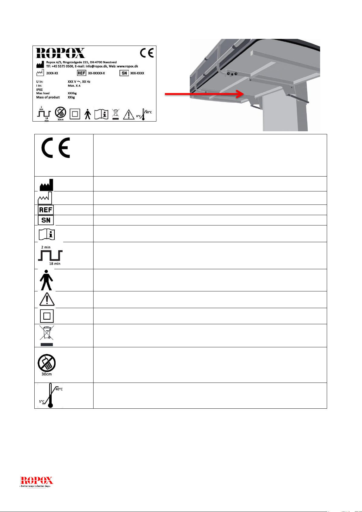
2.1 Product label
This product is CE-marked in accordance with the
European Medical Device Directive 93/42/EEC, including
amendments incorporated in Directive 2007/47/EEC.
It also complies with all relevant requirements in the
Council Directive 2006/42/EC on
machinery
Manufacturer name and address
Date of production
Stock number
Serial number
Consult manual before use
Operating interval of electrically operated equipment. The use of electrical height
adjustable equipment can run at maximum 2 minutes, followed by an 18-minute
break.
Type B applied part. The product complies with IEC 60601-1 requirements to
provide protection against electric shock.
Consult manual for important safety related information, warnings and safety
precautions.
Class II, double isolated electrical components.
Do not dispose as unsorted municipal waste. Product must be returned to a
designated recycling station.
Mobile phones or other portable RF emitting equipment should be no closer to the
product than 30cm.
Operating and storing temperatures may not exceed 5-40C°

PDF 6210 / DRAFT Rev001
7
3. General requirements
3.1 Product information
Manufacturer:
Ropox A/S
Ringstedgade 221, DK-4700 Naestved
+45 55 75 05 00
Info@ropox.com
Product models
Part number
Model
Configuration
40-30604-3
40-30606-3
40-30608-3
40-30610-3
40-30611-3
Vario 120x70cm
Vario 140x70cm
Vario 160x70cm
Vario 180x70cm
Vario 190x70cm
MDD Class
93/68/EEC
Class I
Applied part classification
60601-1
Type B applied part
MEE Class
60601-1
Class II
Height adjustment
30-100cm
Speed of actuation
≈ 26mm/s
Maximum user weight
according to
EN12182:2012
200kg
Power supply
230V ~50Hz
I in
Max 8A
Intermittence
2min on / 18min off
IP rating
IPX6
Ambient temperature
5-40C° Operation and storage
Materials in contact with
patient
Table top surface
Mattress
(accessories)
Bed guards
(accessories)
Lifting unit
Compact laminate surface.
Dahlia fabric
Backing: 100% polyester
Coating: 100% Polyurethane
ISO 10993-10 Non Allergic
St37 tube construction with powder coating.
St37 tube construction with powder coating.
Aluminium anodiseret with powder coating.
Intended environments
This product is to be used only in:
Proffesional Healtcare Environment
Homecare Environment
The device is not intended for use in special environments as defined by IEC
60601-1-2
Accessories
Mattresses
40-25760-1
40-25795-1
40-25796-1
40-25764-1
40-25765-1
Bed guards
40-30196-1
40-30197-1
Cushion for bed guard
40-25782-1
40-25783-1
For L= 120cm
For L= 140cm
For L= 160cm
For L= 180cm
For L= 190cm
For L=120cm, 140cm
For L=160cm, 180cm, 190cm
For L=120cm, 140cm
For L=160cm, 180cm, 190cm

PDF 6210 / DRAFT Rev001
8
3.2 Intended use
Vario is a fixed, height adjustable & foldable changing bed that can be used for care of children and adults
up to 200 kg. The changing bed is inteded for use i private homes, institutions, day care centers and similar
institutions and for people with physical or mental disabilities. The product is designed to provide optimum
working conditions for caregivers. The changing bed can be used in both dry and wet rooms (conditions), but
must not be used as a shower bed.
The height of tabletop (changing bed) can be adjusted infinitely from 30-100 cm using the hand control and
can be folded up for spare saving when not in use.
3.3 Intended operator
Reading and understanding this manual will be sufficient training for an intended operator. Children nor
patient are not considered intended operator.
3.4 Dimension sketch
Model
Lenght
(L)
40-30604-3
120cm
40-30606-3
140cm
40-30608-3
160cm
40-30610-3
180cm
40-30611-3
190cm
The ceiling height must be at least 2,35m
32cm
115cm
13cm

PDF 6210 / DRAFT Rev001
9
4. Instructions for use
4.1 Receiving the Vario changing bed
Vario is a wall fixed changing bed. It is delivered partly assembled. Connecting the product to mains will
make it operational.
Vario will come in two packages. One for the “Lifting unit” and one for the “tabletop”.
4.2 Placering af el-udtag
Make sure that you allow free space on all sides of the changing bed.
The main power cable (230V) has a total length of approx. 320 cm of which 250 cm is outside the lifting unit.
The cable can be pulled out in either left or right side. The outlet for main power cannot be placed behind the
lifting unit.
Caution!
When connected to the mains the product must be placed in a manner according to
power outlets so that the operator will be able to disconnect the product during use in
case of an emergency.
Warning!
Make sure that the Main 230 V socket is placed according to the national requirements
for such installations.
300cm
250cm

PDF 6210 / DRAFT Rev001
10
4.3 Prepare the mounting
Dismount the top cover plate

PDF 6210 / DRAFT Rev001
11
Slide the front plate out of the Lifting unit to get access to the wall mounting holes in the unit.
!! Be aware not to bend or scratch the front plate in the process !!
PDF 6210 / DRAFT Rev001
12
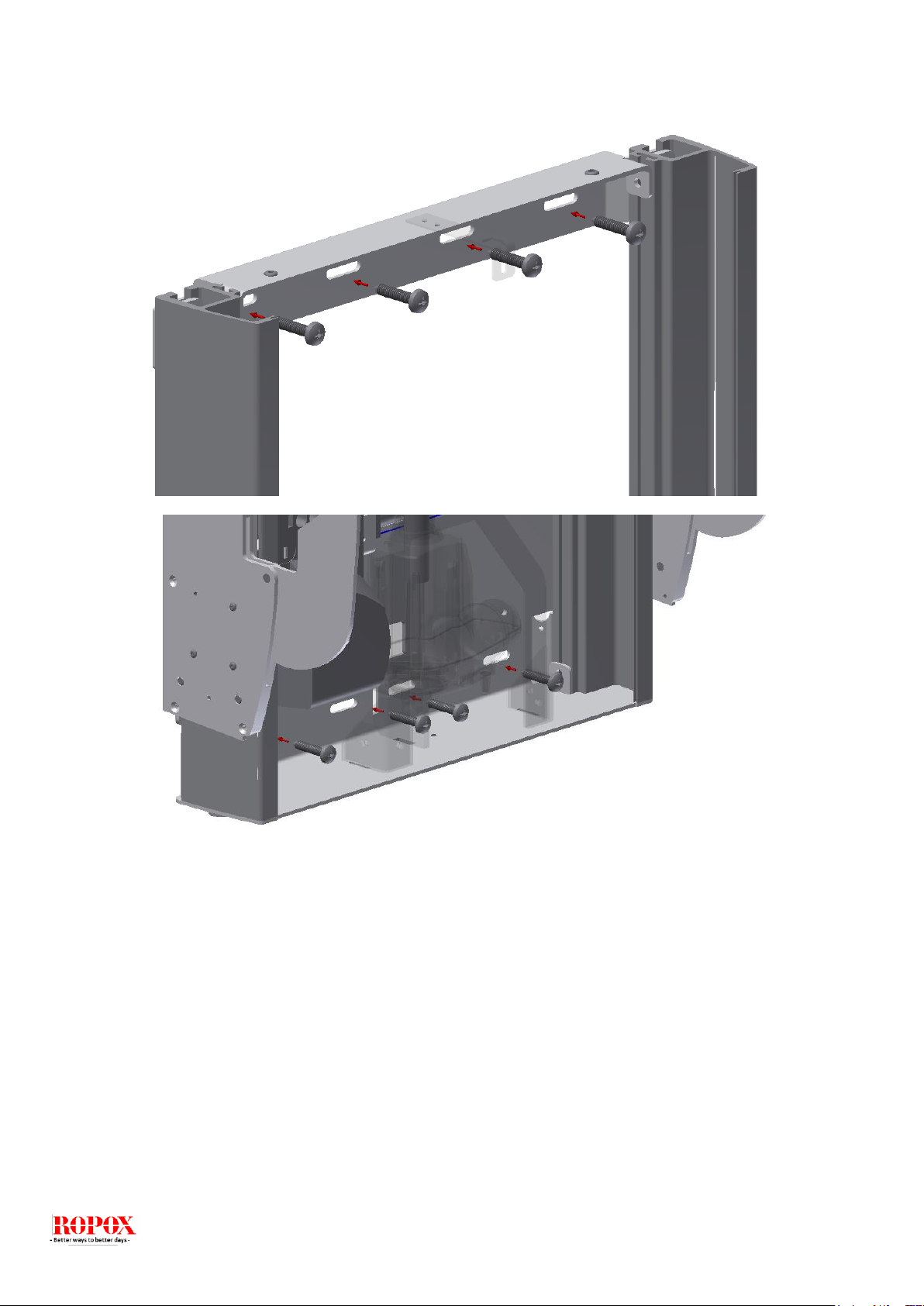
4.4 Mounting to the wall
The attachment holes can be marked up on the wall, four possibilities in the top, and four in the bottom of the
frame. Place the frame against the wall and make sure it is horizontal. The frame is standing on two
adjustable feet. The holes in the frame are all Ø 10 mm. Remove the frame and drill the holes.
Attach the frame securely to the wall by using adequate bolts and rawlplugs suitable for the type of wall
construction / material on site. The Shower bed is being supplied with a set (8 pcs) of screws and rawlplugs,
which is ONLY used to mount the unit in a concrete wall. If the unit must be mounted on another kind of wall,
other kinds of plugs and screws must be used.
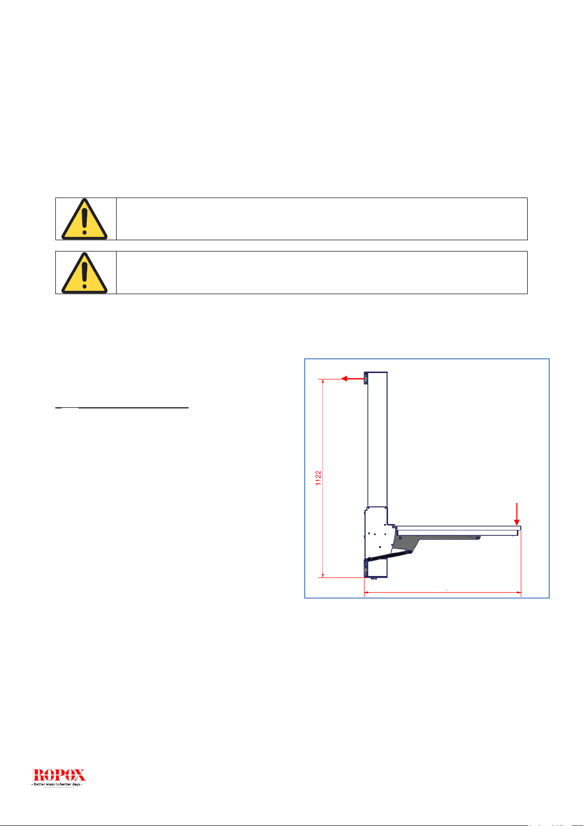
Changing bed has a max user weight of 200 kg.
Maximum load in the top screws are 31kg for each screw.
If you have other objects mounted right next to this changing bed, you have to consider the
risk of trapping, and therefore consider a safe distance to the other objects.
Make sure that no dust or other obstacles are interfering with the rollers, chain, sprocket or
gas springs. This cancause malfunction and damage the system.
Force for each of the four screws in top of the unit::
K
screw
= (200kg * 992mm)/(1122mm * 4 screws)
K
screw
= 44kg for each screw
F=200kg
F=Screw
992
PDF 6210 / DRAFT Rev001
13
Mount the lifting unit to the wall with screws at the top and bottom.

PDF 6210 / DRAFT Rev001
14
Slide the front plate back into the lifting unit.

PDF 6210 / DRAFT Rev001
15
Mount the cover plate on the top of the lifting.

PDF 6210 / DRAFT Rev001
16
4.5 Mount the tabletop on the lifting unit
Slide the tabletop in between the Lifting unit and the support arms on the Lifting unit.
Fasten the tabletop to the Lifting unit with 4 pcs. Screws (M8x12) through the bushings in the support
arms.
Bed guard are accessories

PDF 6210 / DRAFT Rev001
17
5.
4.6 Wire diagram
The changing bed is delivered with the control box already mounted on the frame. The diagram
shows how the cables are connected to the control box.
All the plugs are water tight, and therefore they can be a little tricky to connect / disconnect. Make sure that
the plugs are positioned correctly before they are pushed into the sockets at the control box. The plugs must
be pushed into the sockets until the “O-ring” is no longer visible.
Motor, control box and control switch apply to IPX6. This
means that they are dustproof and water resistent.
The electronic system is designed for periodical use only,
this means a max. duty cycle of 10%; 2min on /18min off.
1. Control box
2. Mains cable 230V
3. Motor, connects to socket 1
4. End plugs, connects to socket 2, 3 & 4
5. Handcontrol, connects to HB socket
1
2 3 4
5

PDF 6210 / DRAFT Rev001
18
4.7 Connecting cables
The changing bed is delivered with the control box already mounted on the frame.
Control switch connects to ”HB”.
When all cables have been connected, use the safe locking
bracket. Pushed in until you hear a “click”.
Mains cable connects to the socket at the side of the box.
Disconnecting cables
Mains cable can be pulled out (no safe locking bracket).
Before the other cables can be disconnected, the safe locking
bracket needs to be released / removed
(use a screwdriver to remove). Locking clips at each end of the
safe locking bracket have to be released
before the bracket can be removed, and the cables can be
disconnected.
To obtain the full IPX6 value, it is very important that all the plugs have been pressed
firmly into the sockets and the safe locking bracket is mounted.
Placement of the handcontrol
Bracket for hand control can be placed at the
wall as shown. To be mounted with the two
screws which are delivered with the bracket.
Hand control should be placed out of
reach of children.
Hand control can be placed in either right
or left side.

PDF 6210 / DRAFT Rev001
19
5. Instructions for use
5.1 Operating the product
5.1.1 Actuation of the product
The product is operated with the spiral cord hand control. Arrow up will move the product
upwards and arrow down will move the product downwards.
Warning!
The product should always be able to travel the full range of actuation without colliding
with objects. Failing to do so will compromise the product stability.
Special care should be taken in ensuring that no children or adults are sited under the
product as severer injury from entrapment may occur.
Indstil KUN skiftelejet i højden når bordpladen er nedslået i vandret position.
Only adjust the product in height position, when the table top are in horizontal
Note!
The control buttons are «push and hold». Height adjustment stops as sonn as the button
is released. This is an inportant safety measure.
Warning!
Before use always make sure that mains cable and hand control cable will be able to
travel freely without the risk of squeezing or disconnecting the product as result of the
movement.

PDF 6210 / DRAFT Rev001
20
5.1.2 Operation of the bed guards
Vario is not supplied with bed guard as standard. This can be ordered as an accessory.
To operate the bed guards pull the rubber tubing placed under the table top to release the locking
mechanism. The bed guard can then be pivoted to the desired mode.
Warning!
Make sure that the bed guard is locked securely in place when in use. Locking is
checked by shaking the bed guard back and forth ensuring that the locking pin is
fully engaged.
PDF 6210 / DRAFT Rev001
21
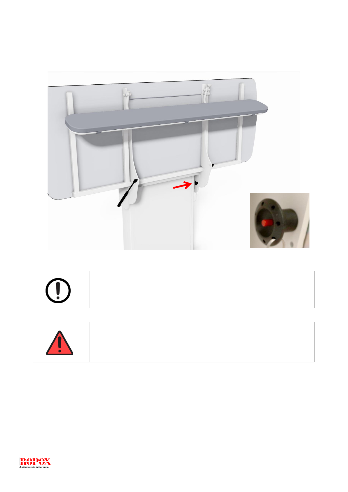
5.1.3 How to fold changing bed up and down
The worktop can be secured against inadvertent folding in upright position by locking the table with the
locking pin.
For folding the worktop in downwards position, remove locking pin and lower top by hand.
Notification!
Prior to folding worktop in upright position, bed guard must be turned underneath
worktop.
Warning!
Always make sure worktop is securely locked in upright position with locking
pin.when left in this position. Check shower bed is locked by pulling the worktop to
ensure locking pin is fully engaged and worktop cannot be lowered.

PDF 6210 / DRAFT Rev001
22
Locking of shower bed
When worktop is folded up, insert locking pin as indicated. Press and hold the red button while inserting the
split. The shower bed is now locked against folding down.
Unlocking of shower bed
For unlocking & folding worktop in downwards position, remove pin. Pin is placed in second hole for storage
when shower bed is being used and folded down. The worktop can now easily be folded up and down.

PDF 6210 / DRAFT Rev001
23
5.2 Recommendations in use
Warning!
NEVER leave a person on the changing bed unattended - not even for a very
short period.
--If two changing beds are mounted next to each other, we recommend to mount a
side cover between, to avoid the trapping risk.
6. Cleaning
Cleaning can be done with lukewarm water and a suitable all purpose cleaning agent. Use a cloth or soft
sponge to wash the product. Dry the product of with a wrung cloth.
Mattresses and cushions
Cover:
Recommended cleaning detergent: Normal soap or alcohol. The alcohol can be used undiluted. The cover
can be removed and machine washed separately at max 95°.
Skum:
Cannot be washed
Notification!
Do not use cleaning agents containing abrasive e.g. scouring powder, steel wool, scouring
sponge.
This product is not designed to be sterilized, autoclaving and sterilization beyond normal
cleaning is may possibly change the product safety and function.
7. Maintenance
Notification!
Failing to comply with periodic maintenance may result of degrading of product function and
safety.
7.1 Periodic maintenance of bed guards
If the product is used humid or dry atmosphere the locking pin may be prone to seizing from lubricants
drying. Besides checking the function of the locking mechanism before every use, a periodic lubrication
of the locking pin every 6 month is recommended.

PDF 6210 / DRAFT Rev001
24
7.2 Fejlsøgning
Problem:
Check:
Vario does not move up or down when the handcontrol switch is pressed
1. Main power connected 230v
2. Motor cable is connected to control box
3. Hand control is connected to control box
4. Motor is overloaded
Hand control defect
1. The product works with another hand
control
By pressing the up or down button,
no movement is achieved, only
clicking sounds is are heard from
control box
1. Plugs are not connected correctly.
Dismount all cables and re-connect.
2. ”Reset”
Press and hold UP ( ) and DOWN ( )
buttons. Keep the buttons depressed until
the control unit has beeped approx. ten
times. After that, the bathtub may be
adjusted to the bottom position for
resetting.
8. Environmental protection
The product is not intended to be disposed as municipal waste. Proper disassembly, sorting
and disposal of components must be done by waste disposal professionals.
Part
Disposal recommendation
Table top
Hard plastic or phenolic composites
Bed guards
Steel waste
Lifting unit
Steel and aluminum
Controlbox
Electronics
Actuator
Electronics
Hand control
Electronics

PDF 6210 / DRAFT Rev001
25
8. Spare parts
#
Name
Part number
1
Control box CB6096-03
97000434
2
Actuator LA34.5
97000431
3
Motor cable L=300mm
97000423
4
230V cable
97000427
5
Ganter Pallet lock with axial
protection
95170115
6
Hand control
97001655
#
Name
40-30604-1
40-30606-1
40-30608-1
40-30610-1
40-30611-1
7
Bed guard
complete *
40-30196-1
40-30196-1
40-30197-1
40-30197-1
40-30197-1
8
Parts for
bed guards
40-30198-1
40-30198-1
40-30199-1
40-30199-1
40-30199-1
9
Table top
Vario
40-30891-1
40-30892-1
40-30893-1
40-30894-1
40-30895-1
*Bed guards complete contains necessary parts for mounting.
*Bed guards are accessories

PDF 6210 / DRAFT Rev001
26
9. Accessories
9.1 Bed guard
Part number
Size
Pcs.
40-30196-1
L= 120cm, 140cm
1
40-30197-1
L= 160cm, 180cm, 190cm
1

PDF 6210 / DRAFT Rev001
27
9.2 Cushion for bed guard
9.3 Mattress
Part number
Size
Pcs.
40-25782-1
L= 120cm, 140cm
1
40-25783-1
L= 160cm, 180cm, 190cm
1
Item number
Size
Thickness
40-25760-1
Madras L=120 cm m/underlag
3 cm
40-25795-1
Madras L=140 cm m/underlag
3 cm
40-25796-1
Madras L=160 cm m/underlag
3 cm
40-25764-1
Madras L=180 cm m/underlag
3 cm
40-25765-1
Madras L=190 cm m/underlag
3 cm
PDF 6210 / DRAFT Rev001
28
10. Electro magnetic compability
10.1 Suitable Environments
The device is suitable for use at home, at daycare centres, at day centres for persons with
physical or mental disabilities or at hospitals except near active HF surgical equipment and the
RF shielded room of an medical electrical system for magnetic resonance imaging, where the
intensity of electromagnetic disturbances is high.
10.2 Basic safety and Essential performance
The device does not have any function related to basic safety or essential performance. In case
of loss or degradation of performance, the user can get on and off the product.
10.3 Adjacent and stacked use
Warning!
Use of this equipment adjacent to or stacked with other equipment should be voided
because it could result in improper operation. If such use is necessary, this equipment
and the other equipment should be observed to verify that they are operating normally
10.4 Cables
Cable component
Lenght
Power cable
2,5m
Hand control spiral cable
Approx. 5 m extended
Warning!
Use of accessories, transducers and cables other than those specified or provided by the
manufacturer of this could result in increased electromagnetic emissions or decreased
electromagnetic immunity of this equipment and result in improper operation.
10.5 RF portable equipment
Warning!
Portable RF communications equipment (including peripherals such as antenna cables
and external antennas) should be used no closer than 30 cm (12 inches) to any part of
the device, including cables specified by the manufacturer. Otherwise, degradation of the
performance of this equipment could result.

PDF 6210 / DRAFT Rev001
29
11. CE – Declaration of conformity
I, the undersigned, hereby declare that the following products:
Ropox Mobilio
Part number
Model
40-30604-1
40-30606-1
40-30608-1
40-30610-1
40-30611-1
Vario 120x70
Vario 140x70
Vario 160x70
Vario 180x70
Vario 190x70
and all accessories belong to risk class I and conform to the following Directives and Standards:
DIRECTIVES European Medical Device Directive 93/42/EEC, including amendments
incorporated in Directive 2007/47/EEC.
Council Directive 2006/42/EC on machinery
STANDARDS
DS/EN 12182:2012 Assistive devices for persons with functional disabilities -
General requirements and test methods.
DS/EN 14971:2012 Medical devices – The use of risk management in connection
with medical devices
DS/EN 9999:2016 Assistive devices for persons with functional disabilities -
Classification and terminology
DS/EN 60601-1-2:2007
+Corr (Mar2010) Elektromedicinsk udstyr - Del 1-2: Generelle krav til grundliggende sikkerhed og
væsentlige funktionsegenskaber - Sideordnet standard: Elektromagnetiske
forstyrrelser - Krav og prøvninger
DS/EN 60601-1:2006 Medical electrical equipment – Part 1: General requirements for basic safety and
essential performance
Næstved, Dato 01-07-2018
ROPOX A/S
Ringstedgade 221
DK – 4700 Næstved
Tel.: +45 55 75 05 00 Fax.: +45 55 75 05 50
E-mail: info@ropox.dk
www.ropox.dk
 Loading...