


Ropox VanityLine Washbasin Electric
User Manual
Mounting Instructions
Keep this folder with product at all times!
PDF 6174 / 25.10.2017
PA 2004 00634
© ROPOX 2017

Page 2
© ROPOX 2013
Contents
1. INTRODUCTION .................................................................................................................................................... 3
2. COMPLIANCE WITH EU-DIRECTIVES ........................................................................................................... 3
3. APPLICATION ........................................................................................................................................................ 3
3.1 Control switch ................................................................................................ ........................................................ 4
4. TECHNICAL DATA VANITYLINE WASHBASIN ............................................................................................ 5
5. DIMENSIONSSKETCH ......................................................................................................................................... 6
6. SUPPLY POINTS, WATER SUPPLY AND WASTE .......................................................................................... 7
6.1 Connection adapters ......................................................................................................................................... 11
7. MOUNTING INSTRUCTIONS ............................................................................................................................ 12
7.1 Mounting of frame ............................................................................................................................................ 12
7.2 Mounting of frame on the wall .......................................................................................................................... 12
7.3 Mounting of spacers .......................................................................................................................................... 13
7.4 Mounting of actuator ........................................................................................................................................ 14
7.5 Mounting of top frame ....................................................................................................................................... 14
7.6 Mounting of wooden fascias ............................................................................................................................. 15
7.7 Mounting of control switch ............................................................................................................................... 16
7.8 Mounting of control unit ................................................................................................................................... 17
7.9 Wiring circuit .................................................................................................................................................... 18
7.10 Mounting of washbasin .................................................................................................................................... 20
7.11 Mounting of water supply and waste ................................................................................................................ 21
8. MOUNTING OF ACCESSORIES ....................................................................................................................... 21
8.1 Mounting of safety strip .................................................................................................................................... 22
8.2 Mounting of hand control ................................................................................................................................. 24
8.3 Mounting of infrared control ................................ ................................ ............................................................ 24
8.4 Pre-setting of maximum water temperature ..................................................................................................... 24
8.5 Mounting of cover plates .................................................................................................................................. 25
8. LIST OF COMPONENTS FOR VANITYLINE WASHBASIN ........................................................................ 27
11. OPTIONS ................................................................................................................................................................ 31
12. SAFETY IN USE .................................................................................................................................................... 32
13. CLEANING/ MAINTENANCE ............................................................................................................................ 33
13.1 Cleaning, frame ........................................................................................................................................... 33
13.2 Cleaning, washbasin .................................................................................................................................... 33
13.3 Maintenance................................................................................................................................................. 33
13.4 Service schedule, operation and maintenance ............................................................................................. 34
14. TROUBLE SHOOTING ........................................................................................................................................ 35
15. SPARE PARTS ....................................................................................................................................................... 36
16. CE-MARKING ....................................................................................................................................................... 37
17. COMPLAINTS ....................................................................................................................................................... 38

Page 3
© ROPOX 2013
1. Introduction
The VanityLine washbasin is electrically height-adjustable from 68-98 cm to obtain optimum working
height. Wheelchair users have unimpeded space up to the wall for better access.
If you have chosen the electrical version, frequent height adjustment can be made through activation
of the control switch on the front fascia of the washbasin. As an option large press pads and remote
control are available on request.
The users of the product must follow these instructions. It is imperative that the instructions have
been read and understood before operation of the product.
The instructions should always be available to the user and accompany the product in the case of
relocation.
The correct use, operation and inspection are decisive factors for efficient and safe performance.
2. Compliance with EU-directives
This product has CE marking and therefore meets the basic requirements concerning performance
and safety of the current Machinery Directive. All types of the Ropox VanityLine washbasins are
made in accordance with the relevant requirements of the Medical Devices Directive No. 93/42/EEC
and are all in the lowest risk class 1.
See separate CE-declaration, page 37.
3. Application
The VanityLine washbasin is adjustable in height in order to obtain optimum working height for user
and helper. Do NOT use VanityLine washbasin as a lifting table or person lifter.
The product should be used indoor, at temperatures and humidity as described in section 4
The control unit complies with IP66 and must always be installed in accordance with the
national Heavy Current Regulations or corresponding national or international standards.
This document must ALWAYS be kept with the product and have been read and
understood by the user.
If this product is electrically adjustable in height there is a risk of squeezing. The
product must therefore always be operated by or under the guidance of an
experienced adult, who has read and understood the importance of section 12 ”Safety
in use”.

Page 4
© ROPOX 2013
3.1 Control switch
Standard control switch:
For height adjustment of washbasin use fixed control switch which is
mounted into front panel of washbasin
Press upwards symbol to raise/lift washbasin and to lower press
downwards symbol
The washbasins stops as soon as control button is released.
Ropox hand control with cable (accessory)
As an alternative hand control with cable can be used.
Hand control works in the same way as switch. As soon as
button is released movement of washbasin will stop.

Page 5
© ROPOX 2013
4. Technical data VanityLine washbasin
Product name: Ropox VanityLine washbasin Electric
Item numbers: Washbasin in the middle 60x50cm: 40-14851
Washbasin to the right 90x50cm: 40-14852
Washbasin to the left 90x50cm: 40-14853
Washbasin to the right 120x50cm: 40-14854
Washbasin to the left 120x50cm: 40-14855
Height adjustment: 68-98 cm electrical, incl. standard washbasin
Type & size of washbasin: Wash basin: 120x50cm, washbasin to the right & left
Wash basin: 90x50cm,washbasin to the right & left
Wash basin: 60x50cm, washbasin in the middle
Monobloc tap: Oras Saga, mixer tap with temperature pre-setting facility.
Alternative mixer taps available.
Contact Ropox for more information.
Material, washbasin: Synthetic/composite marble with gelcoat
Material, frame: Welded steel tube and plate St. 37
Aluminium alloy 606045-T6
Stainless steel spindle and various plastic components
Surface treatment: Blue chromate, powder coating: Standard RAL 9010, mat white
Max. user weight: Max user weight is 250kg. Tested acc. to DS/EN 12182:2012 and
DS/ISO 17966:2016.
Power supply: 230VAC / 2.5A / 50Hz
Standby primary: 7W
Control voltage: 24VDC
Duty circle: 2 min active/ 18 min pause
Speed: Approx. 18 mm/
sec
Lifting time stroke 30 cm: Approx. 17 sec.
Temperature: 10-40°C
Air humidity: 5-85% (non-condensing)
Complaints: See complaints page 38
Producer: Ropox A/S, DK-4700 Naestved, Tel.: +45 55 75 05 00
Mail: info@ropox.dk, www.ropox.com

Page 6
© ROPOX 2013
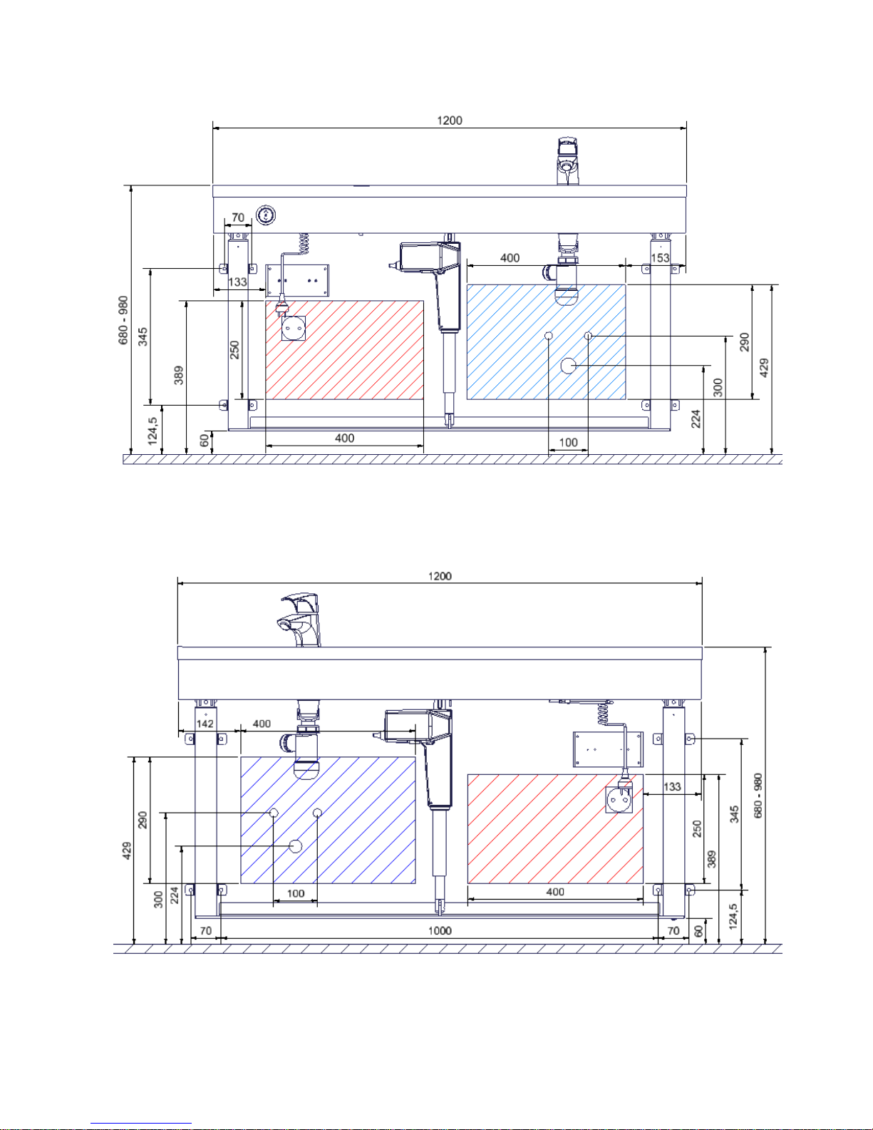
5. Dimensionssketch
40-14851
40-14852 og 40-14853

Page 7
© ROPOX 2013
6. Supply points, water supply and waste
40-14851
40-14854 og 40-14855

Page 8
© ROPOX 2013
40-14852
40-14853
Page 9
© ROPOX 2013
40-14855
40-14854

Page 10
© ROPOX 2013
It is advisable to place water supply and waste within the hatched area. Also it is important to use
flexible hoses for water supply and waste to ensure that the washbasin will move freely without
obstacles within the height adjustment range 68-98 cm including washbasin.
Arrange for the fixed feed pipes on the wall to be pointing up, at a height of 300 mm. This
will ensure that the flexible feed pipes will always flex in a neat curve close to the wall
without kinking. A 90 degree valve with a 1/2" exposed thread is recommended.
The control unit complies with IPX6 and must always be installed in accordance with the
national Heavy Current Regulations or corresponding international or national standards.
The cables to the control unit must be able to move freely during height adjustment of the
washbasin.

Page 11
© ROPOX 2013
6.1 Connection adapters
If the recommendations cannot be met, the components shown below are available
depending on the type of installation in the building.
Water connection adapters
Hoses from washbasin
Adapter
Installation in
room (not provided)
No adapter required
1/2"
Thread
1/2" -> 3/8"
Item No. 97001670
3/8"
Thread
1/2" -> 15mm
Item No. 97001666
15mm
Pipe
Hose extension
Hose from washbasin
Coupling piece
Extra hose
1/2" -> 1/2"
Item No. 97001662
1/2" x 1/2", 0,5m, steel
Item No. 97001123
1/2" x 1/2", 1m, plastic
Item No. 97001120
Drain adapters
Drain hose from washbasin
Adapter
Installation in
room (not provided)
No adapter required
Ø32
Ø32 -> Ø40
Item No. 97001660
Ø40
Ø32 -> Ø50
Item No. 97001661
Ø50
Drain hose extension
Drain hose from washbasin
Coupling piece
Extra drain hose
Ø32-Ø32
Item No. 97001662
Ø32 Flex hose, 40-110cm
Item No. 97001161
Ø32 Flex hose, 27-62cm
Item No. 97001162
1/2”
Ø32
Ø32

Page 12
© ROPOX 2013
7. Mounting instructions
Prior to assembly check that all parts have been provided according to the list of components. See
list of components, page 27.
7.1 Mounting of frame
7.1.1 Slide top bracket for actuator
and the one leg into groove on
underside of aluminum profile.
7.1.2 Slide the other leg into the groove on
from the other side.
7.1.3 Fasten legs with two bolts,
make sure both legs flush with end
of aluminum profile.
7.1.4 Mount the large mounting bracket for the
actuator onto underside of both legs and fix
threaded bolts on the bracket.

Page 13
© ROPOX 2013
7.2 Mounting of frame on the wall
6cm
7.2.1 Place the frame against the wall
and align it. Adjust the two
threaded bolts under the legs to
ensure that the frame is horizontal.
Mark and drill holes for fastening.
Fasten frame to the wall by means
of screws and raw plugs suiting the
material of the wall.
After mounting, the threaded bolts
can be removed.
7.2.2 Misalignments up to 0.45 cm on
the wall may be adjusted by
fitting the provided spacers (0.15
cm) between the legs and the
wall.
Loosen the leg fixings a bit and
push the spacers behind the wall
fittings, as required, at the top or
bottom depending on whether the
wall is vertical.
7.3 Mounting of spacers
7.3.1 In case of skirting boards, you
can use the 1 cm deep
spacers to pack the frame out
from the wall.

Page 14
© ROPOX 2013
7.4 Mounting of actuator
7.4.1a Mount actuator into bracket with
enclosed bolts and locking nuts.
Once actuator is secured with both
fittings, top bracket can be fastened
to aluminum profile
7.4.1b
7.4.1c
7.5 Mounting of top frame
7.5.1 Push the small flat-bar nuts into the
profile. Afterwards push large flat-bar
nuts into profile, one in each
end/side.

Page 15
© ROPOX 2013
7.6.3 Now all three fascias have been
mounted.
7.6.2 To ensure correct positioning of the
wooden fascias they are provided with
marking-out for screws. Fasten the
fascias to the frame from the inside.
6.4.1
7.5.2 Mount the frame of washbasin onto
aluminium profile.
Tighten the screws securely.
7.6 Mounting of wooden fascias
7.6.1 Mount the three wooden fascias on
the frame.

Page 16
© ROPOX 2013
7.7 Mounting of control switch
7.7.1 The control switch for height adjustment must be mounted in the wooden front
fascia.
Choose the required position (right/ left) in the front fascia and drill a 1.8 cm dia.
hole.
7.7.2 Screw cap for control switch into fascia and afterwards mount switch.

Page 17
© ROPOX 2013
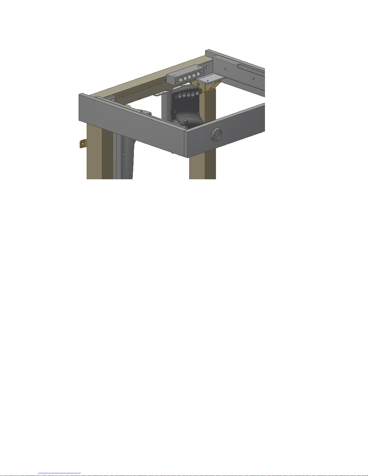
7.8 Mounting of control unit
7.8.1 Turn the two special locking nuts on the control box holder horizontal for them to fit into the
longitudinal track of aluminum profile. Place plates on front side of aluminum profile and fasten M6
screws (the special locking nuts will turn into place once screws are tightened) Secure the little boxes
into two small locking nuts which are inside the profile
For positioning on 40-14852 see point 7.8.1. For positioning on 40-14853 see point 7.8.2.
For positioning on 40-14854 see point 7.8.3. For positioning on 40-14855 see point 7.8.4.
For positioning on 40-14851 see point 7.8.5.
40-14853
7.8.2

Page 18
© ROPOX 2013
40-14854
40-14855
7.8.3
7.8.4
Page 19
© ROPOX 2013
7.8.5
40-14851
Page 20
© ROPOX 2013
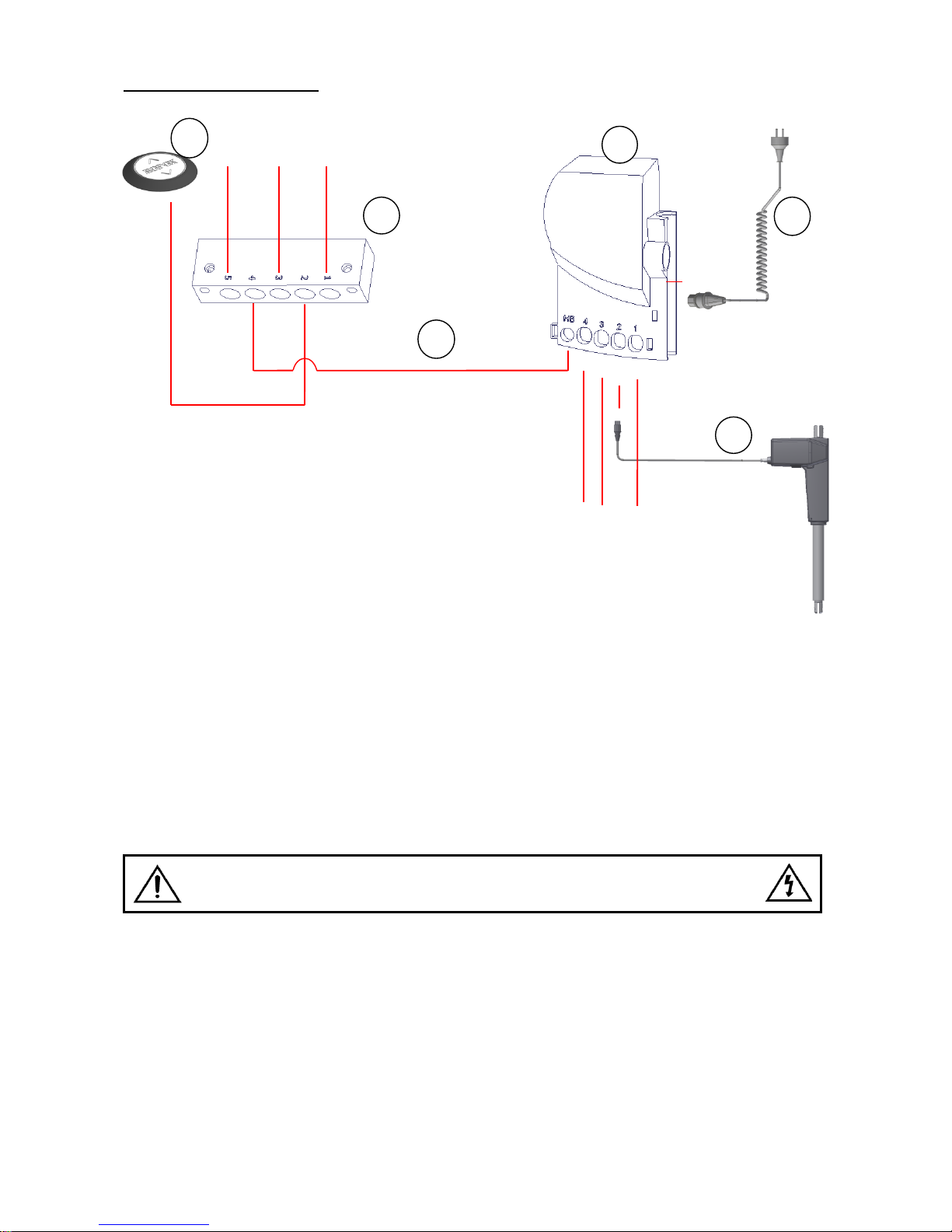
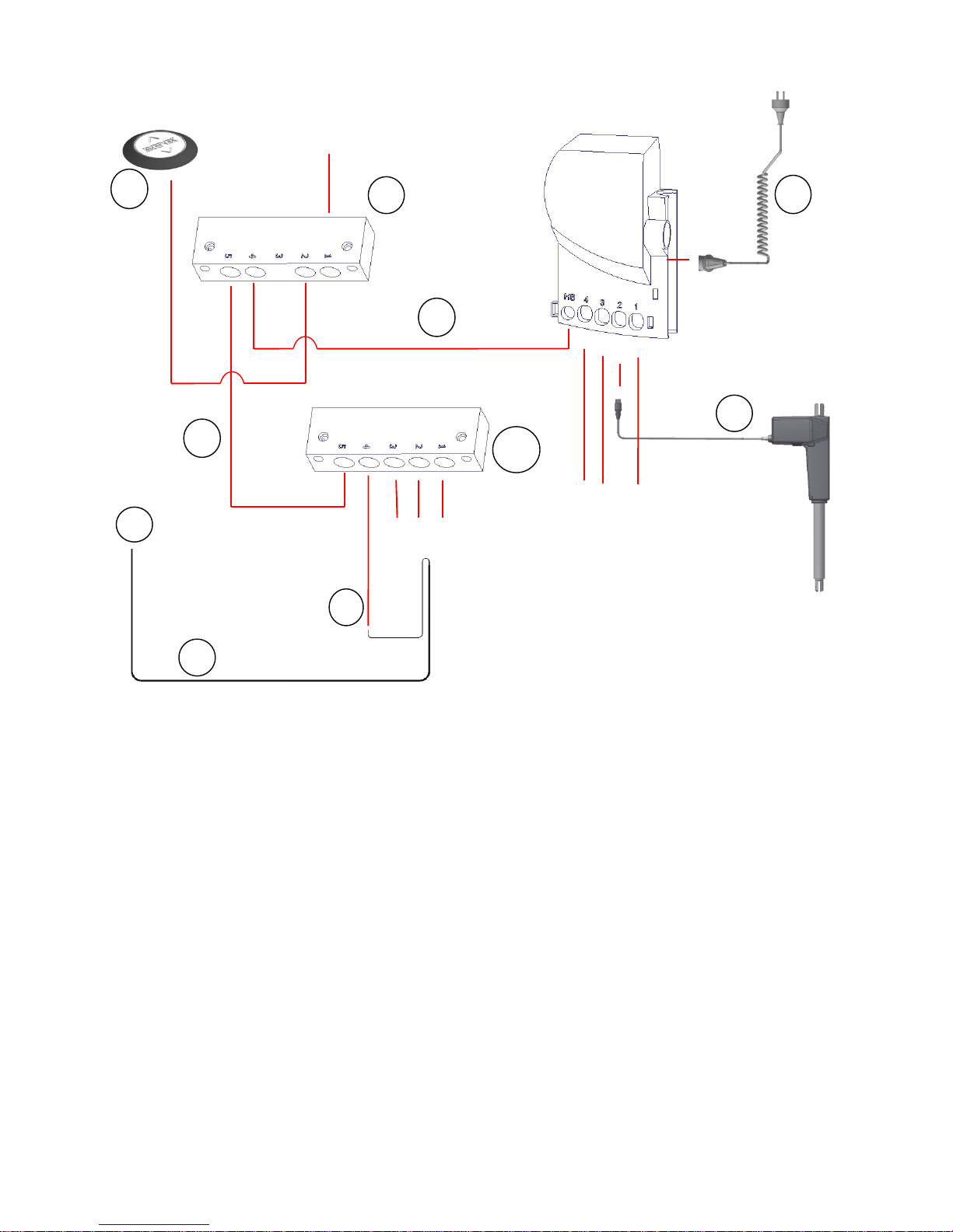
7.9 Wiring circuit
1. Controlbox
2. Mains cable 230V
3. Actuator
4. Transmission box 97001672
5. Control switch
6. Communication cable
3
4
5
Plugs
Plugs
2 1 6
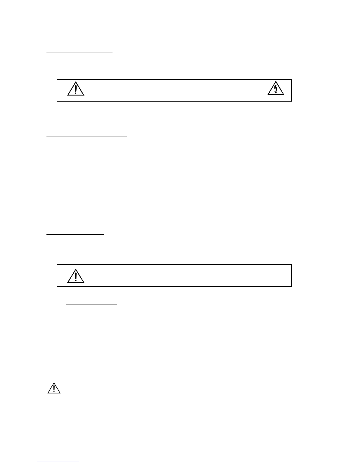
Warning
ALWAYS switch off mains voltage during assembly
Check national regulations to determine the correct location of the control unit.
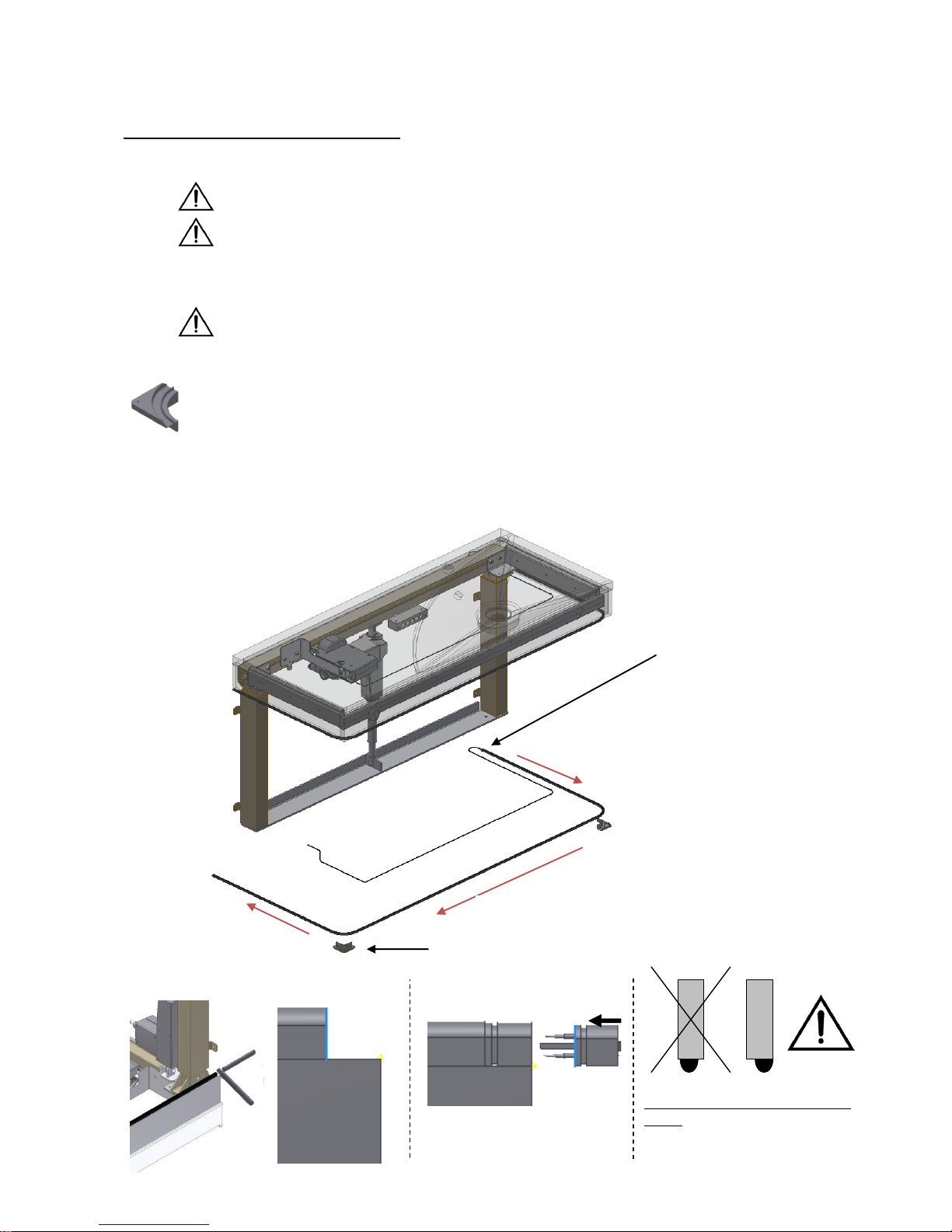
7.9.1 Connect electrical components as shown on above cable diagram.
Screw enclosed cable security plate onto wall and fixate power cable in both ends. The cable has to be able to
move freely during lifting of washbasin into top position. Connect power cable to control box.
Note! Loose cables are placed into enclosed cable duct, which can be mounted onto aluminum profile
Note! Remember to mount filler plugs into contacts that are not used in control boxes and transmission
box.

Page 21
© ROPOX 2013
7.10 Mounting of washbasin
7.10.1 Apply the silicone provided to the
top of the side pieces of the frame.
7.11 Mounting of water supply and waste
7.11.1 Fit the tap hexagon nipples on the pipes
of the water tap.
7.11.2 Screw the connecting hoses
onto the hexagon nipples and
the outlet on the wall. Make sure
that the connecting hoses move
freely within the height
adjustment range.
7.11.3 Mount the waste pipe from the
washbasin as illustrated. The flexible
waste pipe must be able to move
freely within the height adjustment
range.
Page 22
© ROPOX 2013
8. Mounting of accessories
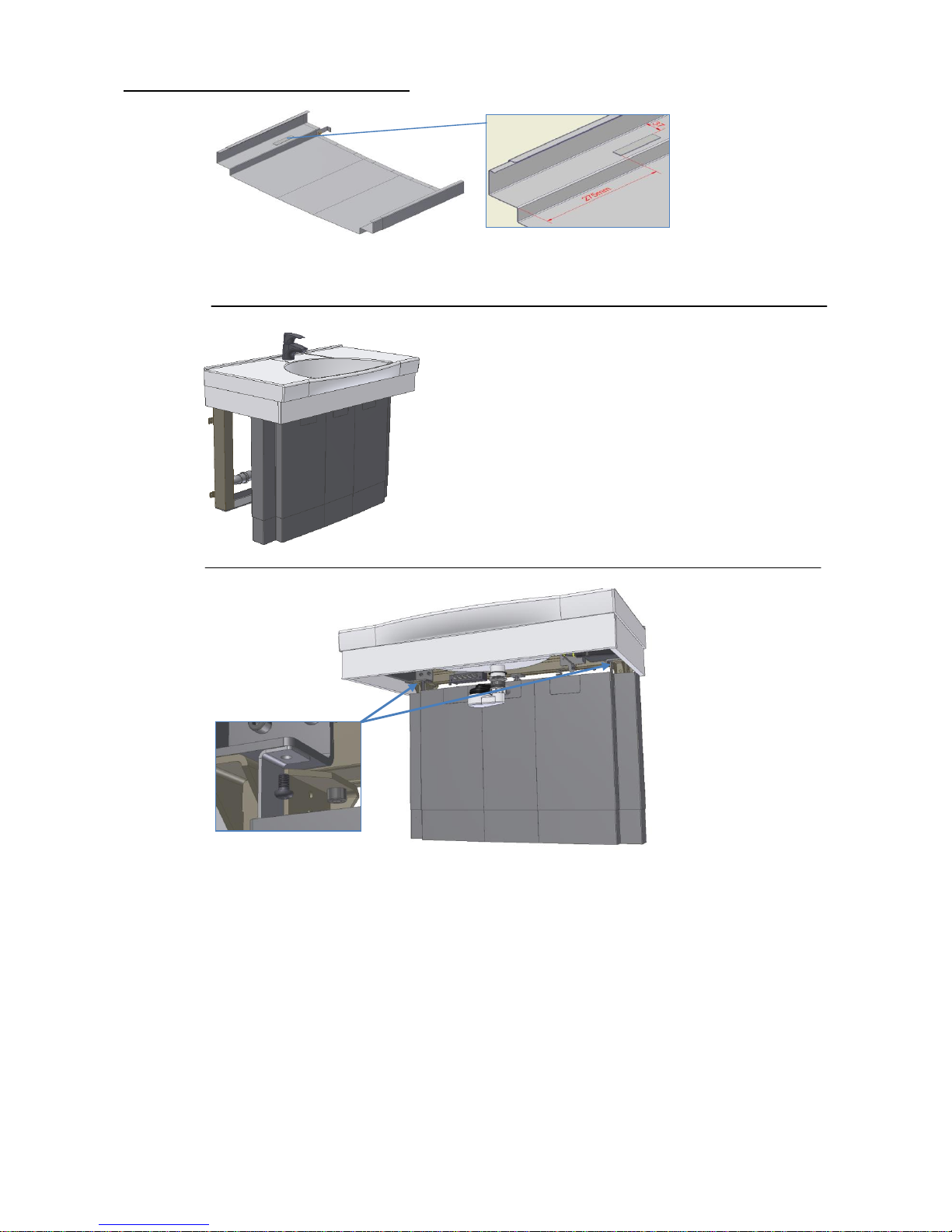
8.1 Mounting of safety strip
Be careful not to damage the safety strip during transport or mounting.
If the safety strip is attached to an uneven or curved surface, whereby it is
bent or distorted, the correct functioning of the safety strip may be
jeopardised.
The surface to which the safety strip has to be attached must be clean, dry
and degreased to obtain optimum adhesion.
Please use provided cleansing tissue
The ”corner guides” should be mounted first as a guide for the safety strip. They
should be placed where the side facia and front fascia meet.
Mount the safety strip on the bottom side of the fascia by means of the double adhesive
tape starting at the furthest point from the control box.
Remove the protective paper of the tape and press on the safety strip. Be aware of the
minimum inside bending radius R
min
=2 cm.
IMPORTANT
1. START
2.
3.
4.
Corner
5. Shorten safety strip
6. Mount end plug
Sectional view of front- and side
fascia
It is extremely important that safety
strip is mounted equate with outer
edge of front/side fascia
Page 23
© ROPOX 2013
Wiring circuit when safety stip is mounted
1. Controlbox
2. Mains cable 230V
3. Actuator
4. Transmission box 97001685
5. Control switch
6. Safety strip
7. End plug
8. Adapter cable for safety strip
9. Communication cable
10. Transmission box 97001410
3
4
5
6
Plugs
Plugs
2
7
8
9
10
9
Plugs
Page 24
© ROPOX 2013
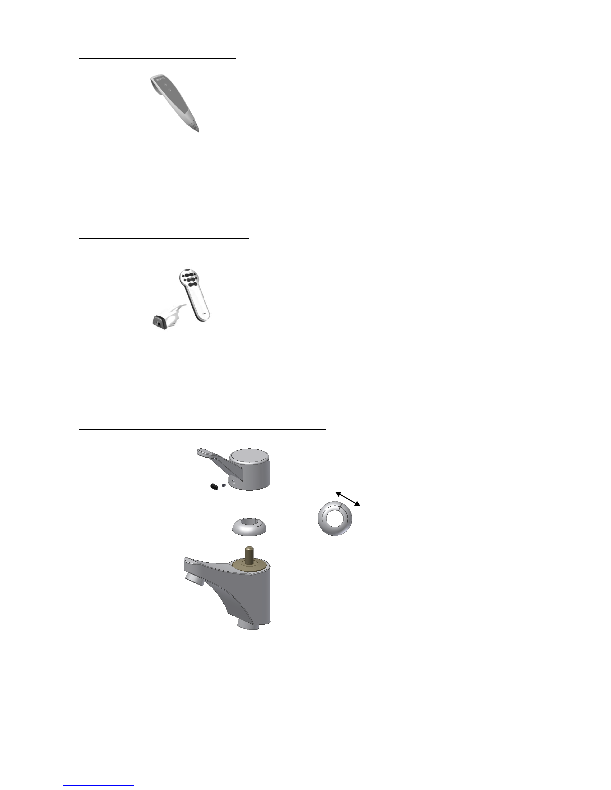
8.2 Mounting of hand control
8.3 Mounting of infrared control
8.4 Pre-setting of maximum water temperature
Dismount the original lever by removing the plastic plug under the lever and loosening the
screw. Now the lever may be pulled off.
By turning the ring to the left, you may reduce the maximum water temperature. If the ring is
turned to the right, the maximum temperature will be increased.
Connect plug of hand control into transmission box where standard
switch is connected.
Receiver box is IPx4 and can be placed underneath the washbasin, for
example on inside of fascias. The cable length of receiver box is 40cm and
operating range of control is approx.10m. The plug of receiver box is
connected into transmission box where standard switch is connected.
cold
Hot
Page 25
© ROPOX 2013
8.5 Mounting of cover plates
8.5.1 Place velcro on both sides of inside cover plate as shown
8.5.2 Remove protection film from Velcro.
Place covers in center of washbasin
and press covers against frame, make
sure that Velcro’s clue side sticks to
frame.
Inside cover must stand on the floor if
washbasin is mounted in
recommended height (see mounting
instruction for washbasin)
8.5.3 Push outer cover plate onto top frame and mount/fasten with 2
pcs M6x10 bolts. Use prepared cutout in cover plate according
to washbasin that is being installed!

Page 26
© ROPOX 2013
9. Performance test
After installation and prior to use, all functions of VanityLine must be tested. The test must be carried
out by competent personnel. Subsequently the test shall be carried out at least once a year:
Testing prior to connection of mains voltage:
1. Check that the mounting instructions have been observed.
2. Check that all bolts have been tightened.
3. Check that all cables have been connected correctly and that the plugs have been
pressed home.
4. Check that there is no load on the Flexi frame.
5. Check that there is nothing preventing the Flexi from moving freely within the height
adjustment range.
Connect main power to control box and continue testing:
1. Press and hold the UP and DOWN buttons and keep them depressed until the control unit
has beeped approx. ten times.
2. Press DOWN on the control switch, move the frame to bottom position, check that the
movement is even and smooth. Make sure that the hose connections follow the movement of
the frame and that they do not get squeezed. The frame is now reset.
3. Press UP on the control switch, move the frame to top position and check that the movement
is even and smooth. Make sure that the hose connections follow the movement of the frame
and that they do not get squeezed.
If a safety strip has been mounted underneath the washbasin it must be tested as follows:
Press DOWN on the control switch and let the washbasin move 2-5 cm downward. Now activate
the safety strip by pressing it lightly. The washbasin must stop the downward movement, move
1-2 cm upward and stop.
If all these tests are ok, the washbasin is ready for use. Se section 12 “Safety in use”.

Page 27
© ROPOX 2013
8. List of components for VanityLine washbasin
VanityLine washbasin 60 cm, 40-14851:
30*65300-060: Alu-profile 1 pc.
30-67636-1: Flexi legs 2 pcs.
The legs comprise:
30-67881: Spacer (0.15 cm) 3 pcs./ leg
30-67680: Spacer (1 cm) 2 pcs./ leg
40*14705-058: Frame for washbasin 122 cm 1 pc.
30*65500-002: Flat-bar nut 2 pcs.
95010814: Bolt M8x14 4 pcs.
95010814: Washer for M8 4 pcs.
60102496: Wooden side fascia, white, 48,2x9x1.6 cm 2 pcs.
60102498: Wooden front fascia, white, 59,6x9x1.6 cm 1 pc.
97001570: Washbasin, 60x50 cm 1 pc.
30*72120-062 Bracket for actuator 1 set
The brackets comprise:
30*65500-073: Actuator bracket top left 1 pc.
40*14851-002: Actuator bracket button 1 pc.
30*65500-003: Flat-bar nut 2 pcs.
95010814: Bolt M8x14 2 pcs.
95011020: Bolt M10x20 4 pcs.
95011035: Bolt M10x35 2 pcs.
95180510: Locking nut M10 2 pcs.
VanityLine washbasin 90cm, right 40-14852:
30*65300-090: Alu-profile 1 pc.
30-67636-1: Flexi legs 2 pcs.
The legs comprise: See above
40*14852-101: Frame for wash basin 90 cm 1 pc.
30*65500-002: Flat-bar nut 2 pcs.
95010814: Bolt M8x14 4 pcs.
95010814: Washer for M8 4 pcs.
60102496: Wooden side fascia, white, 48,2x9x1.6 cm 2 pcs.
60102497: Wooden front fascia, white, 89,6x9x1.6 cm 1 pc.
97001572: Washbasin, right 90x50 cm 1 pc.

Page 28
© ROPOX 2013
30*72120-015 Bracket for actuator 1 set
The brackets comprise:
30*65500-076: Actuator bracket top left 1 pc.
30*72120-025: Actuator bracket button 1 pc.
30*65500-003: Flat-bar nut 2 pcs.
95010814: Bolt M8x14 2 pcs.
95011020: Bolt M10x20 4 pcs.
95011035: Bolt M10x35 2 pcs.
95180510: Locking nut M10 2 pcs.
VanityLine washbasin 90cm, left 40-14853:
Contains the same parts as specified in item 40-14852
97001571: Washbasin, left 90x50 cm 1 pc.
VanityLine washbasin 120 cm, right 40-14854:
30*65300-120: Alu-profile 1 pc.
30-67636-1: Flexi legs 2 pcs.
The legs comprise: See above:
40*14854-101: Frame for washbasin 120 cm 1 pc.
30*65500-002: Flat-bar nut 2 pcs.
95010814: Bolt M8x14 4 pcs.
95010814: Washer for M8 4 pcs.
60102496: Wooden side fascia, white, 48,2x9x1.6 cm 2 pcs.
60102499: Wooden side fascia, white, 119,6x9x1,6 cm 1 pc.
97001574: Washbasin, 120x50 cm, 1 pc.
30*72120-059 Bracket for actuator 1 set
The brackets comprise:
30*65500-076: Actuator bracket top left 1 pc.
30*72120-060: Actuator bracket button 1 pc.
30*65500-003: Flat-bar nut 2 pcs.

Page 29
© ROPOX 2013
95010814: Bolt M8x14 2 pcs.
95011020: Bolt M10x20 4 pcs.
95011035: Bolt M10x35 2 pcs.
95180510:Locking nut M10 2 pcs.
VanityLine washbasin 120 cm, left 40-14855:
Contains the same parts as specified in item 40-14854
97001573: Washbasin, left 120x50 cm 1 pc.
8.3 Common plumbing parts
Electrical parts
40*14705-039: Control box holder (90+120cm wash basin) 1 stk.
30*72120-020: Control box holder (60cm wash basin) 1 stk.
97000465: Actuator 1 stk.
97000474: Actuator cable 1 stk.
97000421: Control box 1 stk.
97001410: Transmission box 1 stk.
97000440: Communication cable 1 stk.
97000429: Plug oval 2 stk.
97001412: Plug round 2 stk.
97001701: Control switch 1 stk.
40*43043-033: Cap for control switch 1 stk.

Page 30
© ROPOX 2013
97003000: Silicone tube 1 pc.
97001601: Prevex water trap 1 pc.
97001162: Flexible waste pipe, Ø32/32 1 pc.
27-62cm (60cm wash basin)
97001161: Flexible waste pipe, Ø32/32 1 pc.
40-100cm (90cm and 120cm wash basin)
97001035: Elbows 32mmx 88,5°, white 2 pcs.
97001045: Bottom valve with plug for overflow 1 pc.
97001046: Foam packing 1 pc.
97001008: Ball chain with coupling link 1 pc.
97001012: Hexagon nipple 2 pcs.
97001120: Connecting hoses, ½” x ½”, 100 cm 2 pcs.
97001320: Mixer tap, Oras Saga 1 pc.
Lever length 8 cm from centre
96000155: Adhesive pads 5 pcs.
Cable tidy strips 5 pcs.

Page 31
© ROPOX 2013
11. Options
Safety strip for 60 cm washbasin 40-14857: 1 pc.
Safety strip for 90 cm washbasin 40-14858: 1 pc.
Safety strip for 120 cm washbasin 40-14859: 1 pc.
Infrared control, 30-72002-1: 1 pc.
Cover plate 60cm 40-14865: 1 set
Cover plate 90cm 40-14866: 1 set
Cover plate 120cm 40-14867: 1 set
Hand control, 40-14868-1:
Incl. 14141-018 hand control holder 1 set
This model is for use on washbasin WITHOUT safety strip.
Hand control, 40-14869-1:
Incl. 14141-018 hand control holder 1 set
This model is for use on washbasin with safety strip

Page 32
© ROPOX 2013
12. Safety in use
The VanityLine washbasin should only be used by people, who have read and understood
these instructions.
VanityLine washbasin is a height-adjustable washbasin and should not be used as a lifting
table or person lifter.
On electrically height-adjustable washbasins we recommend the fitting of safety stop rails in
order to guard against and avoid injury and accidents. Nevertheless, always make sure that
there are no people, animals or objects under the washbasin during height adjustment.
Always use the washbasin so there is no risk of damage to people or property. The person,
who operates the washbasin, is responsible for avoiding damage or injury.
If the washbasin is used in publicly accessible locations where children or people with
reduced observation ability may get close to the washbasin, the person operating the wash
basin must pay sufficient attention in order to prevent dangerous situations.
Make sure that there is free space above and below the washbasin to allow height
adjustment.
Do not overload the washbasin and make sure that the load distribution is correct.
Do not operate the washbasin in case of errors or damage.
Do not use the washbasin in an explosive environment.
Any modification of the washbasin, which may influence its operation or construction, is
forbidden.
Installation, service and repairs must be carried out by competent personnel.
In case of inspections, service or repairs make sure that the washbasin is not loaded.
If the washbasin has not been installed in accordance with these mounting instructions, the
guarantee may become void.
Only use Ropox original spare parts as replacement parts. If other spare parts are used, the
guarantee may become void.
Page 33
© ROPOX 2013
13. Cleaning/ maintenance
13.1 Cleaning, frame
The wash basin may get dirty during use. It is very important to clean the washbasin frame as
described in these instructions.
Clean the frame with a damp cloth using lukewarm water and ordinary cleaning agents. Do not use
Corrosive/ abrasive liquids or abrasive cloths, brushes or sponges. After cleaning dry the frame.
13.2 Cleaning, washbasin
The washbasin is made of a composite material of marble and synthetic granulates with a gel coat
surface. This gives a hard and hardwearing finish, which is easy to keep clean. Wash the surfaces
daily and dry with a cloth. Do not use cleaning agents containing abrasives, e.g. steel wool, scouring
powder or sulphur acid.
If the water is calcareous, deposits may occur. Remove these calcareous deposits once a week with
a cleaning agent containing citric acid, ethanoic acid or phosphoric acid. Leave the cleaning agent
for 5-10 minutes, depending on the thickness of the deposits, and clean with a soft sponge.
Disinfection of the washbasin may be made using customary disinfectants.
13.3 Maintenance
The frame is maintenance-free and the moving parts have been lubricated for life. For reasons of
safety and reliability we recommend inspection of the frame once a year.
During inspections:
Check that all bolts have been tightened.
Check that the frame moves freely from bottom to top position without problems.
Resetting the washbasin: Press DOWN on the control switch and move the frame to
bottom position. Press DOWN once more and keep the switch depressed for 5 sec. to reset
the control unit. Check that the movement is even and smooth. Make sure that the mains
cable moves freely.
Check that water and waste pipes are tight and undamaged.
Check that all cables have been fitted correctly and are undamaged.
After each inspection the service schedule shall be filled in. See item 13.4.
Only use Ropox original spare parts as replacement parts. If other parts are used, the
guarantee may become void.
Inspections, service and repairs must be carried out by competent personnel
The frame must not be connected to the mains voltage during cleaning.
Do not flush electrical components with water.

Page 34
© ROPOX 2013
13.4 Service schedule, operation and maintenance
Service and maintenance Serial No.
Date:
Signature:
Remarks:
Service and maintenance Serial No.
Date:
Signature:
Remarks:
Service and maintenance Serial No.
Date:
Signature:
Remarks:
Service and maintenance Serial No.
Date:
Signature:
Remarks:
Service and maintenance Serial No.
Date:
Signature:
Remarks:
Service and maintenance Serial No.
Date:
Signature:
Remarks:
Service and maintenance Serial No.
Date:
Signature:
Remarks:
Service and maintenance Serial No.
Date:
Signature:
Remarks:

Page 35
© ROPOX 2013
14. Trouble shooting
a) The frame seems loose or unstable
The screws assembling the frame have not been securely tightened.
Tighten all screws of the frame, see mounting instructions.
b) The wash basin is not horizontal in relation to the wall
After installation of the frame the washbasin will be loaded. This deflection may be balanced by
repeating item 7.2.2 of the mounting instructions.
c) The height of the washbasin cannot be adjusted (adjustment seems very difficult)
1. Check mains and voltage to the control unit and that power is switched on
2. Check cables and plug-in connections between control box and motor/motors. If The control
box makes several click sounds the plug-in connections are not correct
3. Check cables and plug-in connections between control box and control switch
4. Check cable connections between safety stop and control box
5. Check safety stop has not been activated
Page 36
© ROPOX 2013
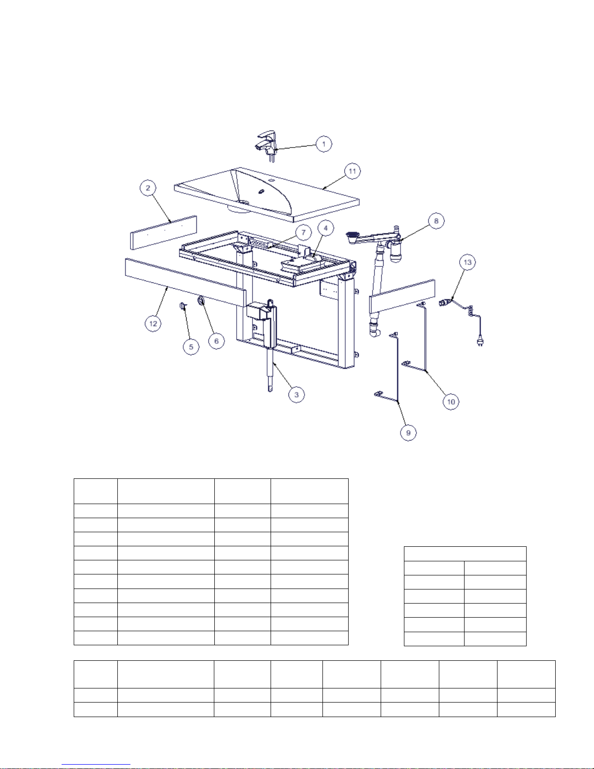
15. Spare parts
#
Description
Quantity
per product
60x50cm
90x50cm
right
90x50cm
left
120x50cm
right
120x50cm
left
11
Washbasin
1
97001570
97001572
97001571
97001574
97001573
12
Wooden front fascia
1
60102498
60102497
60102497
60102499
60102499
#
Description
Quantity
per product
Item no.
1
Mixer tap
1
40-44040
2
Wooden side fascia
2
60102496
3
Actuator
1
97000465
4
Controlbox
1
97000421
5
Control switch
1
97001701
6
Cap for control switch
1
40-43043-033
7
Transmission box
1
97001672
8
Plumbing kit
1
40-14830-013
9
Motor cable
1
97000474
10
Communication cable
1
97000440
Power cables
Type/Region
Item no.
DK
97000427
UK
97000435
Australien
97000436
Japan
97000438
USA
97000461

Page 37
© ROPOX 2013
16. CE-marking
The undersigned hereby declares that the following products:
Ropox VanityLine washbasin electric
Washbasin 60x50cm: 40-14851
Washbasin 90x50 cm right : 40-14852
Washbasin 90x50 cm left: 40-14853
Washbasin 120x50 cm right: 40-14854
Washbasin 120x50 cm left: 40-14855
all belong to risk class I and conform to the Directives and Standards mentioned below:
DIRECTIVES
Medical Devices Directive No. 93/42/EEC (risk class 1)
Machinery Directive No. 2006/42/EC, amended by Directive No. 98/37/EC.
STANDARDS
DS/EN 1041: 2009 Information supplied by the manufacturer of medical devices.
DS/EN 12182: 2012 : Assistive devices for persons with functional disabilities -
General requirements and test methods.
DS/EN 14971: 2012 : Medical devices – The use of risk management in connection with medical
devices.
DS/EN 60204-1 : Safety on machinery – Electrical equipment of machines -
Part 1: General requirements.
DS/EN 60601-1 : Medical electrical equipment – Part 1: General requirements for basic safety
and essential performance.
(Applying to the electrical components of the product).
DS/EN 9999: 2011: Assistive devices for persons with functional disabilities -
Classification and terminology.
Dato: ___01-11-2017_____

Page 38
© ROPOX 2013
17. Complaints
We refer to our General Terms of sale and delivery on our homepage www.ropox.com
ROPOX A/S
Ringstedgade 221
DK – 4700 Naestved
Tel.: +45 55 75 05 00 Fax.: +45 55 75 05 50
E-mail: info@ropox.dk
www.ropox.com
 Loading...