


RESISTRON
RES-406
GB
Operating
instructions
Important features
• Microprocessor technology
• Complete control via PROFIBUS-DP interface
• Automatic zero calibration (AUTOCAL)
• Automatic optimization (AUTOTUNE)
• Automatic configuration of the secondary voltage and current ranges
(AUTORANGE, as of February 2006)
• Automatic phase angle compensation (AUTOCOMP, as of February 2006)
• Automatic frequency adjustment
• Large current and voltage range
• Booster connection as standard
• 0…10VDC analog output for ACTUAL temperature
• Alarm function with fault diagnosis
• Heatsealing band alloy and temperature range selectable
22.6.09
Industrie-Elektronik GmbH Tel: +49/(0)7142/7776-0 E-Mail: info@ropex.de
Gansäcker 21 Fax: +49/(0)7142/7776-19 Internet: www.ropex.de
D-74321-Bietigheim-Bissingen (Germany) Data subject to change

Contents
1 Safety and warning notes . . . . . . . . . . . . . . 3
1.1 Use . . . . . . . . . . . . . . . . . . . . . . . . . . . 3
1.2 Heatsealing band . . . . . . . . . . . . . . . . 3
1.3 Impulse transformer . . . . . . . . . . . . . . 3
1.4 Current transformer PEX-W2/-W3 . . . . 3
1.5 Line filter . . . . . . . . . . . . . . . . . . . . . . . 4
1.6 Warranty provisions . . . . . . . . . . . . . . . 4
1.7 Standards / CE marking . . . . . . . . . . . 4
2 Application . . . . . . . . . . . . . . . . . . . . . . . . . . 4
3 Principle of operation . . . . . . . . . . . . . . . . . 5
4 Description of the controller . . . . . . . . . . . 6
5 Accessories and modifications . . . . . . . . . 6
5.1 Accessories . . . . . . . . . . . . . . . . . . . . . 6
5.2 Modifications (MODs) . . . . . . . . . . . . . 7
6 Technical data . . . . . . . . . . . . . . . . . . . . . . . 8
7 Dimensions . . . . . . . . . . . . . . . . . . . . . . . . 10
8 Installation . . . . . . . . . . . . . . . . . . . . . . . . . 10
8.1 Installation procedure . . . . . . . . . . . . 10
8.2 Installation steps . . . . . . . . . . . . . . . . 11
8.3 Power supply . . . . . . . . . . . . . . . . . . . 12
8.4 Line filter . . . . . . . . . . . . . . . . . . . . . . 13
8.5 Current transformer PEX-W3 . . . . . . 13
8.6 Wiring diagram (standard) . . . . . . . . . 14
8.7 Wiring diagram with booster
connection . . . . . . . . . . . . . . . . . . . . . 15
9 Startup and operation . . . . . . . . . . . . . . . . 16
9.1 View of the controller . . . . . . . . . . . . . 16
9.2 Controller configuration . . . . . . . . . . . 16
9.3 Replacing and "burning in" the
heatsealing band . . . . . . . . . . . . . . . . 18
9.4 Startup procedure . . . . . . . . . . . . . . . 19
10 Controller functions . . . . . . . . . . . . . . . . . 21
10.1 Indicators and controls . . . . . . . . . . . 21
10.2 PROFIBUS communication
„up to Jan. 2006“/“as of Feb. 2006“ . . 23
10.3 Device master file (GSD) . . . . . . . . . . 23
10.4 PROFIBUS protocol . . . . . . . . . . . . . 24
10.5 Input data . . . . . . . . . . . . . . . . . . . . . . 26
10.6 Output data . . . . . . . . . . . . . . . . . . . . 28
10.7 Parameter data . . . . . . . . . . . . . . . . . 30
10.8 DPV1 protocol extension
(as of GSD Version v2.0) . . . . . . . . . . 35
10.9 Temperature indication (actual value
output) . . . . . . . . . . . . . . . . . . . . . . . . 38
10.10 Booster connection . . . . . . . . . . . . . . 39
10.11 Diagnostic interface/visualization software
(as of February 2006) . . . . . . . . . . . . 39
10.12 System monitoring/alarm output . . . . 39
10.13 Error messages . . . . . . . . . . . . . . . . . 40
10.14 Fault areas and causes . . . . . . . . . . . 45
11 Factory settings . . . . . . . . . . . . . . . . . . . . . 46
12 Maintenance . . . . . . . . . . . . . . . . . . . . . . . . 47
13 How to order . . . . . . . . . . . . . . . . . . . . . . . . 48
14 Index . . . . . . . . . . . . . . . . . . . . . . . . . . . . . . 49
Page 2 RES-406

Safety and warning notes
!
!
4–
10 K
–
!!!
1 Safety and warning notes
This RESISTRON temperature controller is
manufactured according to DIN EN 61010-1. In the
course of its manufacture it passed through quality
assurance, whereby it was subjected to extensive
inspections and tests.
It left the factory in perfect condition.
The recommendations and warning notes contained in
these operating instructions must be complied with, in
order to guarantee safe operation.
The device can be operated within the limits indicated
in the "Technical Data" without impairing its operational
safety. Installation and maintenance may only be
performed by technically trained, skilled persons who
are familiar with the associated risks and warranty
provisions.
1.1 Use
RESISTRON temperature controllers may only be used
for heating and temperature control of heatsealing
bands which are expressly suitable for them, and
providing the regulations, notes and warnings
contained in these instructions are complied with.
In case of non-compliance or use contrary to
the intended purpose, there is a risk that
safety will be impaired or that the heatsealing band,
electrical wiring, transformer etc. will overheat.
Ensuring such compliance is the personal
responsibility of the user.
The RESISTRON temperature controller must be set
and coded according to the temperature coefficient of
the heatsealing band.
The use of incorrect alloys with a too low
temperature coefficient and incorrect coding
of the RESISTRON temperature controller lead to
uncontrolled heating and ultimately to burn-out of
the heatsealing band!
The heatsealing bands that were originally supplied
must be identified by detail specification, part number
or some other means that will assure that replacement
bands are identical.
1.3 Impulse transformer
A suitable impulse transformer is necessary to ensure
that the control loop functions perfectly. This
transformer must be designed according to VDE 0570/
EN 61558 (isolating transformer with reinforced
insulation) and have a one section bobbin. When the
impulse transformer is installed, suitable shock
protection must be provided in accordance with the
national installation regulations for electrical
equipment. In addition, water, cleaning solutions and
conductive fluids must be prevented from seeping into
the transformer.
Incorrect installation of the impulse
transformer impairs electrical safety.
1.2 Heatsealing band
1.4 Current transformer PEX-W2/-W3
A basic prerequisite for reliable and safe operation of
the system is the use of suitable heatsealing bands.
The resistance of the heatsealing band which
is used must have a positive minimum
temperature coefficient in order to guarantee
trouble-free operation of the RESISTRON
temperature controller.
The temperature coefficient must be specified as
follows:
e.g. Alloy-20: TCR = 1100 ppm/K
NOREX: TCR = 3500 ppm/K
The current transformer supplied with the RESISTRON
temperature controller is an integral part of the control
system.
Only the original ROPEX PEX-W2 or PEX-W3
current transformer may be used. Other
transformers may cause the equipment to
malfunction.
The current transformer may only be operated if it is
connected to the RESISTRON temperature controller
correctly (see section 9, "Startup and operation"). The
relevant safety instructions contained in section 8.3,
"Power supply", must be obeyed. External monitoring
modules can be used in order to additionally increase
RES-406 Page 3

Application
operating safety. They are not included in the scope of
supply of the standard control system and are
described in a separate document.
1.5 Line filter
The use of an original ROPEX line filter is mandatory in
order to comply with the standards and provisions
mentioned in section 1.7 "Standards / CE marking" on
page 4. This device must be installed and connected
according to the instructions contained in section 8.3,
"Power supply" as well as the separate documentation
enclosed with the line filter.
1.6 Warranty provisions
The statutory provisions for warranties apply for a
period of 12 months following the delivery date.
All devices are tested and calibrated in the factory.
Devices that have been damaged due to faulty
connections, dropping, electrical overloading, natural
wear, incorrect or negligent handling, chemical
influences or mechanical overloading as well as
devices that have been modified, relabeled or
otherwise altered by the customer, for example in an
attempt to repair them or install additional components,
are excluded from the warranty.
Warranty claims must be examined in the factory and
approved by ROPEX.
1.7 Standards / CE marking
The controller described here complies with the
following standards, provisions and directives:
DIN EN 61010-1
(VDE 0411-1)
DIN EN 60204-1 Electrical equipment of machines
EN 50081-1 EMC interference emissions
EN 50082-2 EMC interference immunity:
Compliance with these standards and provisions is only
guaranteed if original accessories and/or peripheral
components approved by ROPEX are used. If not, then
the equipment is operated on the user's own
responsibility.
The CE marking on the controller confirms that the
device itself complies with the above-mentioned
standards.
It does not imply, however, that the overall system also
fulfils these standards.
It is the responsibility of the machine manufacturer and
of the user to verify the completely installed, wired and
operationally ready system in the machine with regard
to its conformity with the safety provisions and the EMC
directive (see also section 8.3, "Power supply"). If
peripheral components (e.g. the transformer or the line
filter) from other manufacturers are used, no functional
guarantee can be provided by ROPEX.
Safety provisions for electrical
measuring, control and laboratory
devices (low voltage directive).
Overvoltage category III, pollution
severity 2, safety class II.
(machinery directive)
according to EN 55011, group 1,
class B
ESDs, RF radiation, bursts, surges.
2 Application
This RESISTRON temperature controller is an integral
part of the "Series 400", the outstanding feature of
which is its microprocessor technology. All
RESISTRON temperature controllers are used to
control the temperature of heating elements
(heatsealing bands, beaded bands, cutting wires,
heatsealing blades, solder elements etc.), as required
in a variety of heatsealing processes.
Page 4 RES-406
The controller is most commonly used for impulseheatsealing PE films in:
• Vertical and horizontal f/f/s machines
• Pouch, filling and sealing machines
• Film wrapping machines
• Pouch-making machines
• Group packaging machines
•etc.
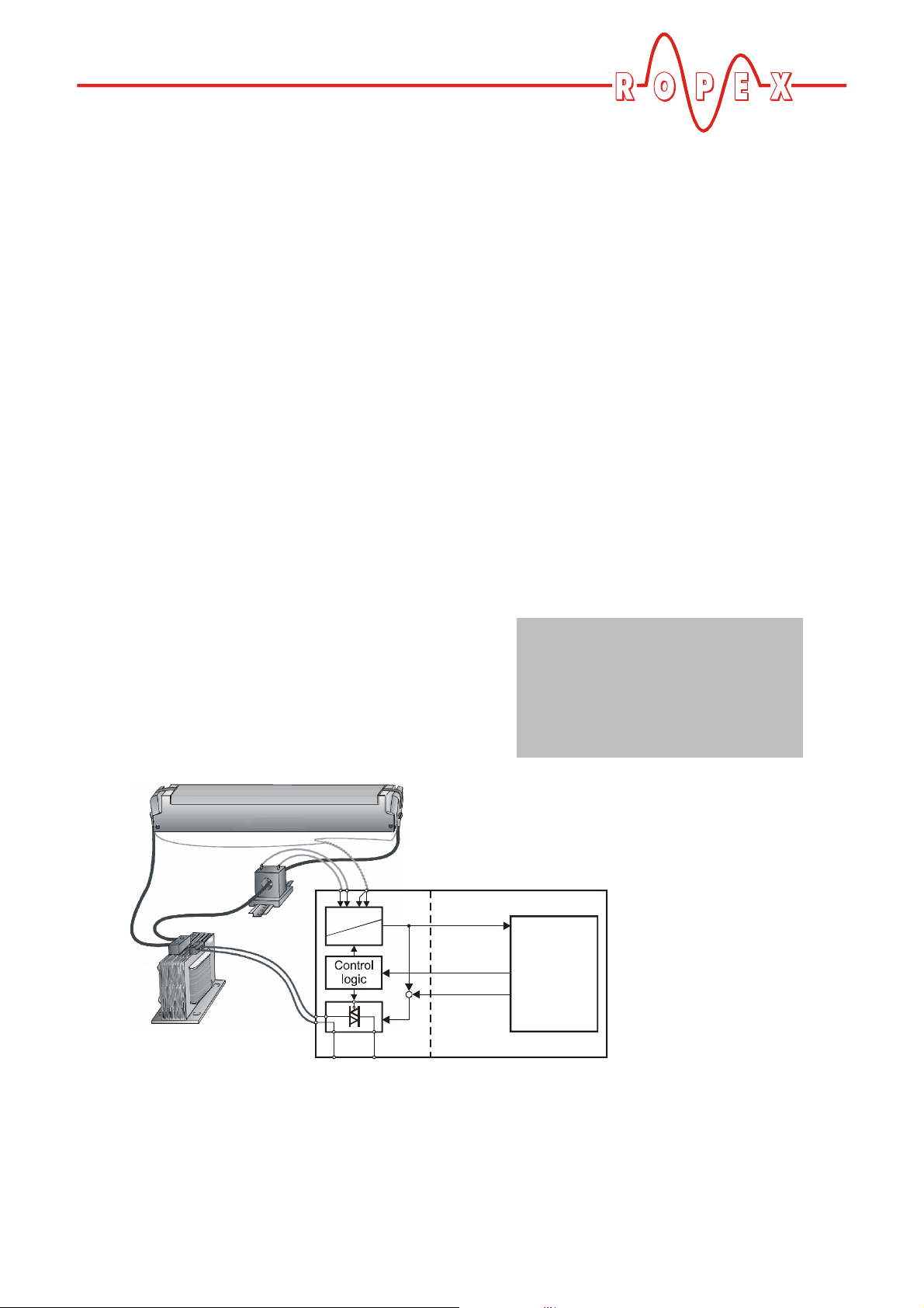
Principle of operation
R=f(T)
Start
and
controls
or
Actual value
LINE
Heatsealing band R = f (T)
Current
transformer
Impulse transformer
URI
R
prim.
U
1
sec.
U
2
The use of RESISTRON temperature controllers
results in:
• Repeatable quality of the heatseals under any
conditions
3 Principle of operation
The resistance of the heatsealing band, which is
temperature-sensitive, is monitored 50x per second
(60x at 60Hz) by measuring the current and voltage.
The temperature calculated with the help of these
measurements is displayed and compared with the set
point.
The primary voltage of the impulse transformer is
adjusted by phase-angle control, if the measured
values deviate from the set point. The resulting change
in the current through the heatsealing band leads to a
change in the band temperature and thus also its
resistance. This change is measured and evaluated by
the RESISTRON temperature controller.
The control loop is closed: ACTUAL temperature = SET
temperature. Even minute thermal loads on the
heatsealing band are detected and can be corrected
quickly and precisely.
A highly high response thermo-electric control loop is
formed which is highly accurate because purely
electrical variables are measured at a high sampling
rate. A high secondary current can be controlled
because power is controlled on the primary side of the
• Increased machine capacity
• Extended life of the heatsealing bands and teflon
coatings
• Simple operation and control of the sealing process
transformer. This allows optimum adaptation to the
load and to the required dynamic range despite the
exceptionally compact dimensions of the controller.
PLEASE NOTE!
RESISTRON temperature controllers play a significant
role in enhancing the performance of modern
machines. However, the full benefit can only be
obtained from the advanced technology offered by this
control system if all the system components, in other
words the heatsealing band, the impulse transformer,
the wiring, the timing signals and the controller itself,
are carefully compatible and interrelated.
We will be pleased to
contribute our many
years of experience
towards optimizing your
heatsealing system.
RESISTRON controller
Indicators
_
+
Set point
RES-406 Page 5
bus interface
4 Description of the controller
Description of the controller
The microprocessor technology endows the
RESISTRON temperature controller RES-406 with
previously unattainable capabilities:
• Very simple operation thanks to AUTOCAL, the
automatic zero calibration function.
• Good dynamic response of the control system
thanks to AUTOTUNE, which adapts automatically
to the controlled system.
• High precision thanks to further improved control
accuracy and linearization of the heatsealing band
characteristic.
• High flexibility: The AUTORANGE function (as of
February 2006) covers a secondary voltage range
from 0.4V to 120 V and a current range from 30A to
500A.
• Automatic adjustment to the line frequency in the
range from 47 Hz to 63 Hz.
• Increased protection against dangerous conditions,
such as overheating of the heatsealing band.
The RESISTRON temperature controller RES-406 is
equipped with a PROFIBUS-DP interface. This
interface can be used to control all the controller
functions and interrogate controller information.
The ACTUAL temperature of the heatsealing band is
supplied to the PROFIBUS interface and to an analog
0 to 10V DC output. The real heatsealing band
temperature can thus be displayed on an external
temperature meter (e.g. ATR-x).
The RES-406 features an integrated fault diagnosis
function, which tests both the external system
(heatsealing band, wiring etc.) and the internal
electronics and outputs a selective error message in
case of a fault.
To increase operational safety and interference
immunity, all PROFIBUS signals are electrically
isolated from the controller and the heating circuit.
Either coding switches on the temperature controller
itself or the PROFIBUS interface can be used to adapt
to different heatsealing band alloys (Alloy-20, NOREX
etc.) and set to the required temperature range
(0…300°C, 0…500 °C etc.).
The compact design of the RESISTRON temperature
controller RES-406 and the plug-in connections make
this controller easy to install.
5 Accessories and modifications
A wide range of compatible accessories and peripheral
devices are available for the RESISTRON temperature
controller RES-406. They allow it to be optimally
adapted to your specific heatsealing application and to
your plant's design and operating philosophy.
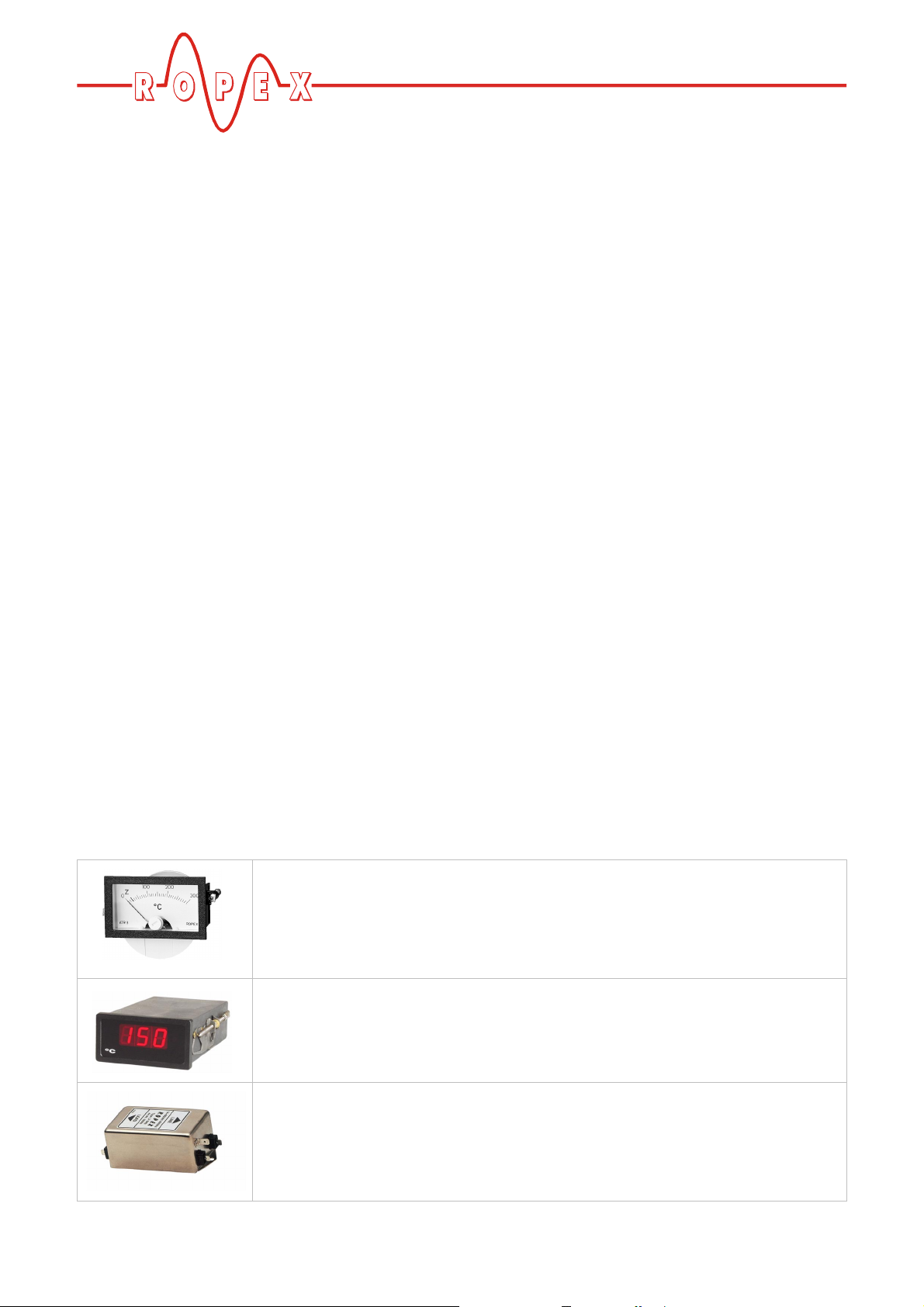
Analog temperature meter ATR-x
For front panel mounting or mounting on a top hat rail (DIN TS35 rail).
Analog indication of the ACTUAL temperature of the heatsealing band in °C. The
meter damping of the unit is optimized for the abrupt temperature changes that occur
in impulse mode.
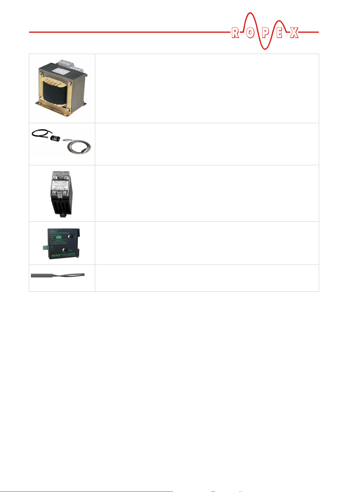
Digital temperature meter DTR-x
For front panel mounting or mounting on a top hat rail (DIN TS35 rail).
Digital indication of the ACTUAL temperature of the heatsealing band in °C, with
HOLD function.
Line filter LF-xx480
Essential in order to ensure CE conformity.
Optimized for the RESISTRON temperature controller.
5.1 Accessories
The products described below are only a few of the
wide range of accessories available for RESISTRON
temperature controllers ("Accessories" leaflet).
Page 6 RES-406
Accessories and modifications
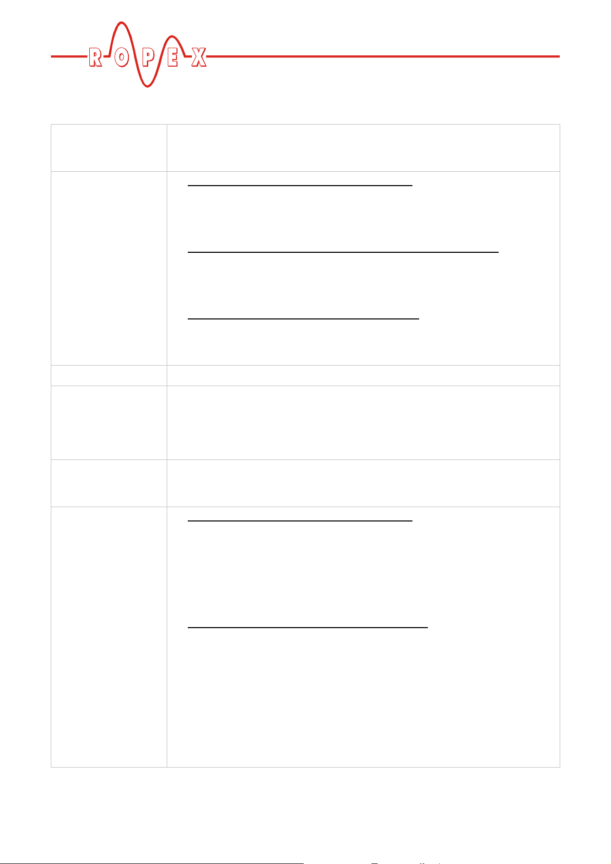
Impulse transformer ITR-x
Designed according to VDE 0570/EN 61558 with a one section bobbin.
Optimized for impulse operation with RESISTRON temperature controllers.
Specified according to the heatsealing application
( ROPEX Application Report).
Communication interface CI-USB-1
Interface for connecting a RESISTRON temperature controller with diagnostic interface (DIAG) to the PC (USB port). Associated PC visualization software for displaying setting and configuration data, and for recording SET and ACTUAL temperatures in real time.
Booster B-xxx400
External switching amplifier, necessary for high primary currents (continuous
current > 5A, pulsed current > 25A).
Monitoring current transformer
For detecting frame short-circuits on the heatsealing band.
Used as an alternative to the standard PEX-W2/-W3 current transformer.
Measurement cable UML-1
twisted measurement cable for the U
Trailing cable, halogene und silicone free.
5.2 Modifications (MODs)
Owing to its universal design, the RESISTRON
temperature controller RES-406 is suitable for a very
wide range of heatsealing applications.
One modification (MOD) is available for the
RESISTRON temperature controller RES-406 for
implementing special applications.
-voltage measurement.
R
MOD 01
Amplifier for low secondary voltages
(U
= 0.25…16VAC). This modification is necessary,
R
for example, for very short or low-resistance
heatsealing bands.
RES-406 Page 7
6 Technical data
Type of construction Housing for installation in the electrical cabinet
Snaps onto a standard top hat rail (DIN TS35 rail, 35 mm) acc. to DIN EN 50022
Dimensions: 90 x 75 mm; height: 135mm (incl. terminals)
Line voltage All controllers manufactured as of February 2006:
115VAC version: 110VAC -15%…120VAC +10% (equivalent to 94…132VAC)
230VAC version: 220VAC -15%…240VAC +10% (equivalent to 187…264VAC)
400VAC version: 380VAC -15%…415VAC +10% (equivalent to 323…456VAC)
All controllers manufactured as of January 2004 up to January 2006:
115VAC version: 115VAC -15%…120VAC +10% (equivalent to 98…132VAC)
230VAC version: 230VAC -15%…240VAC +10% (equivalent to 196…264VAC)
400VAC version: 400VAC -15%…415VAC +10% (equivalent to 340…456VAC)
All controllers manufactured up to December 2003:
115VAC, 230VAC or 400VAC, tolerance: +10 % / -15 %
Technical data
depending on version selected ( section 13 "How to order" on page 48)
Line frequency 47…63Hz, automatic adjustment to frequencies in this range
24VDC-Supply
voltage
Terminals 5+7 or
PROFIBUS plug,
pins 2+7
PROFIBUS-DP
interface
Heatsealing band
type and temperature
range
24VDC, Imax = 100mA
Tolerance: +10 / -10%
The 24VDC-Supply voltage can be fed either via terminals 5 and 7 or via the
PROFIBUS plug at pins 2 and 7.
Baud rates: 9.6kbaud; 19.2kbaud; 45.45kbaud; 93.75kbaud; 187.5kbaud;
500kbaud; 1.5Mbaud; 3Mbaud; 6Mbaud; 12Mbaud
Plug acc. to IEC 61158
All controllers manufactured as of February 2006:
The temperature range and temperature coefficient settings can also be specified
by means of the ROPEX visualization software ( section 10.11 "Diagnostic
interface/visualization software (as of February 2006)" on page 39) in addition to
the rotary coding switch (see below):
Temperature range: 200°C, 300°C, 400°C or 500°C
Temperature coefficient: 400…4000ppm (variable setting range)
All controllers manufactured as of start of production:
Five different ranges can be set with the rotary coding switch or via the PROFIBUS
interface:
Temperature coefficient 1100ppm, 0…300 °C (e.g. Alloy-20)
Temperature coefficient 780ppm, 0…300 °C (e.g. Alloy L)
Temperature coefficient 1100ppm, 0…500 °C (e.g. Alloy-20)
Temperature coefficient 780ppm, 0…500 °C (e.g. Alloy L)
Temperature coefficient 3500 ppm, 0…300°C (e.g. NOREX)
The settings for a temperature coefficient of 780ppm are only available on
controllers manufactured as of October 2003.
Page 8 RES-406

Technical data
!
Analog output
(actual value)
Terminals 17+18
Alarm relay
0…10V DC, Imax = 5 mA
Equivalent to 0…300°C or 0…500°C
Accuracy: ±1% add. 50mV
= 50V (DC/AC), I
U
max
= 0.2A, changeover contact, potential-free
max
Terminals 12, 13, 14
Maximum load
(primary current of
I
= 5 A (duty cycle = 100%)
max
I
= 25A (duty cycle = 20 %)
max
impulse
transformer)
Power dissipation max. 20W
Ambient
+5…+45°C
temperature
Degree of protection IP20
Installation If several controllers are installed on one top hat
rail (DIN TS35 rail), a clearance of at least 20mm
should be allowed between them.
The moving clip required for fastening must be
facing down for mounting on a horizontal top hat
rail.
End holders to mechanical fix the controller must be fitted at both ends for
mounting on a vertical top hat rail.
Weight Approx. 0.7kg (incl. connector plug-in parts)
Housing material Plastic, polycarbonate, UL-90-V0
Connecting cables
Type / cross-sections
Rigid or flexible; 0.2…2.5mm² (AWG 24…12)
Plug-in connectors
If ferrules are used, they must be crimped in accordance
with DIN 46228 and IEC/EN 60947-1.
This is essential for proper electrical contact in the terminals.
RES-406 Page 9
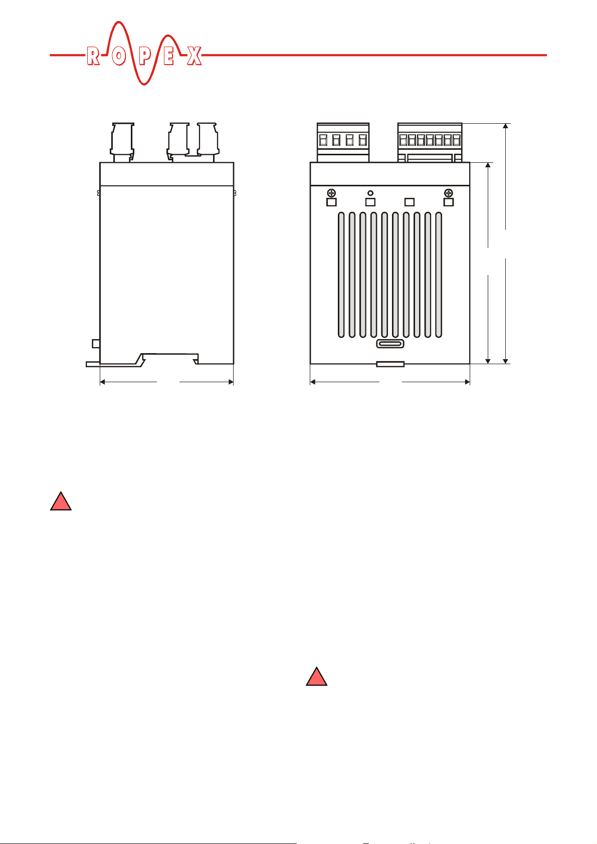
7 Dimensions
!
!
Dimensions
135.0
113.0
75.0 90.0
8 Installation
See also section 1 "Safety and warning notes" on
page 3.
Installation and startup may only be
performed by technically trained, skilled
persons who are familiar with the associated risks
and warranty provisions.
8.1 Installation procedure
Proceed as follows to install the RESISTRON
temperature controller RES-406:
1. Switch off the line voltage and verify that the circuit
is de-energized.
2. The supply voltage specified on the nameplate of
the RESISTRON temperature controller must be
identical to the line voltage that is present in the
plant or machine. The line frequency is
automatically detected by the RESISTRON
temperature controller in the range from
47Hz...63Hz.
3. Install the RESISTRON temperature controller in
the electrical cabinet on a standard top hat rail (DIN
TS35 rail, according to DIN EN 50022). If several
controllers are installed on one top hat rail, the
minimum clearance specified in section 6 "Technical
data" on page 8 must be allowed between them.
4. Wire the system in accordance with the instructions
in section 8.3 "Power supply" on page 12,
section 8.6 "Wiring diagram (standard)" on page 14
and the ROPEX Application Report. The information
provided in section 8.2 "Installation steps" on
page 11 must also be heeded.
5. Connect the RESISTRON temperature controller to
the PROFIBUS master using a cable according to
IEC 61158.
Check the tightness of all the system
connections, including the terminals for the
impulse transformer windings.
6. Make sure that the wiring conforms to the relevant
national and international installation regulations.
Page 10 RES-406

Installation
Impulse
transformer
PEX-W2/-W3
U (prim.)
1
U (sec.)
2
A
F
meter
ATR -x
Digital
PD-x
Avoid long
cables
Heatseal element
with coppered ends
suitable temperature coefficient
controllers installed on
one top hat rail
No additional
resistance
in secondary
circuit
Dimension
transformer correctly
- Secondary voltage
- Power
- Duty cycle
correctly
Sufficient wire
cross-section
Twi sted
wires I
R
wires directly to
Line filter
LF-xx480
(up to Jan. 2006)
8.2 Installation steps
Use heatseal bands with
Heatsealing band R= f (T)
Note
number
of turns
Current transformer
Temperature
No
push-on
connectors
Connect U measuring
heatsealing band ends
Current measuring
R
Line
Note
direction
of rotation
Note
polarity
20mm clearance if several
Controller
potentiometer
Configure
DIP switches
RES-406 Page 11
8.3 Power supply
controller
U
R
I
R
R
PRIM.
U
1
Kb
Ka
SEC.
U
2
GND/
Earth
N (L2)
L1
(L1)
ON
OFF
K1
3
1
Short wires
2
2
Line
115VAC, 230VAC, 400VAC
50/60Hz
Circuit breaker
Double-pole, C characteristic
( ROPEX Application Report)
Short-circuit protection only.
RESISTRON temperature controller not protected.
!
Relay Ka
For "HEAT ON - OFF" function (all-pole) or
"EMERGENCY STOP".
Line filter
The filter type and size must be determined according to
the load, the transformer and the machine wiring
( ROPEX Application Report).
Do not run the filter supply wires (line side) parallel
to the filter output wires (load side).
!
RESISTRON temperature controller belonging to the
4xx Series.
Relay Kb
Load break (all-pole), e.g. in combination with the alarm
output of the temperature controller.
When using a series resistor RV-....-1 the relay Kb
shall be installed.
!
Impulse Transformer
Designed according to VDE 0570/EN 61558 (isolating
transformer with reinforced insulation). Connect core to
ground.
Use transformers with a one section bobbin. The
power, duty cycle and voltage values must be
determined individually according to the application
( ROPEX Application Report and "Accessories" leaflet
for impulse transformers).
!
Wiring
The wire cross-sections depend on the application
( ROPEX Application Report).
Guide values:
Primary circuit: min. 1.5mm², max. 2.5mm²
Secondary circuit: min. 4.0mm², max. 25mm²
These wires must always be twisted (>20/m)
These wires must be twisted (>20/m) if several control
loops are laid together ("crosstalk").
Twisting (>20/m) is recommended to improve EMC.
LINE
Installation
I
>
LINE
I
>
FILTER
3
ROPEX
temperature
3
Page 12 RES-406
Installation
!
!
LINE
PE
wire to ground
Large cross-section
wire to ground
Large frame contact surface
Do not lay parallel
Mounting plate (galvanized)
ROPEX
controller
Snap-on for DIN-rail 35 x 7,5mm or 35 x 15mm (DIN EN 50022)
terminal
block
terminal
wires
23
28
26
39
8.4 Line filter
To comply with EMC directives – corresponding to
EN 50081-1 and EN 50082-2 – RESISTRON control
loops must be operated with line filters.
These filters damp the reaction of the phase-angle
control on the line and protect the controller against line
disturbances.
The use of a suitable line filter is part of the
standards conformity and a prerequisite of
the CE mark.
ROPEX line filters are specially optimized for use in
RESISTRON control loops. Providing that they are
Large cross-section
installed and wired correctly, they guarantee
compliance with the EMC limit values.
You can find the exact specification of the line filter in
the ROPEX Application Report calculated for your
particular heatsealing application.
For more technical information: "Line filter"
documentation.
It is permissible to supply several
RESISTRON control loops with a single line
filter, providing the total current does not exceed
the maximum current of the filter.
The wiring instructions contained in section 8.3 "Power
supply" on page 12 must be observed.
max. 1m
8.5 Current transformer PEX-W3
The PEX-W3 current transformer supplied with the
RESISTRON temperature controller is an integral part
24
60
temperature
of the control system. The current transformer may only
be operated if it is connected to the temperature
controller correctly ( section 8.3 "Power supply" on
page 12).
75
12
14
14
RES-406 Page 13
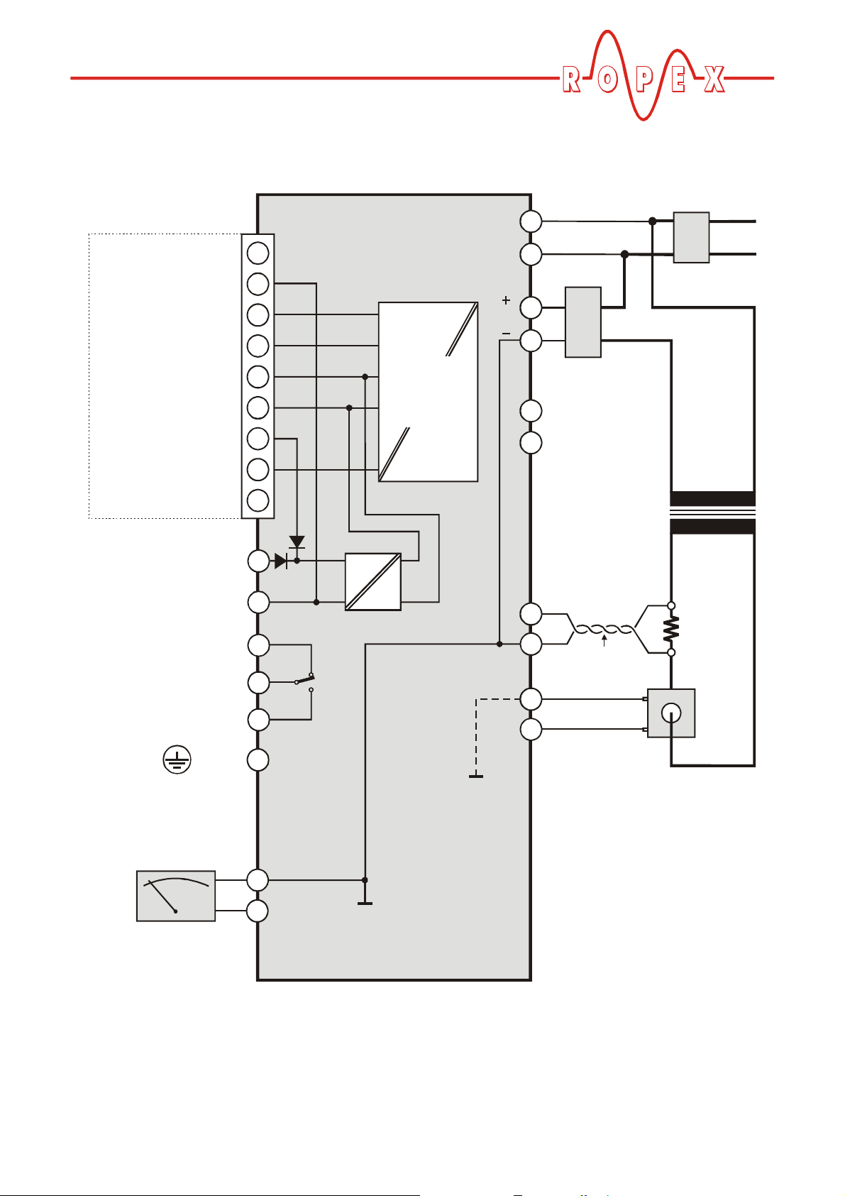
8.6 Wiring diagram (standard)
RES-406
9
8
7
6
5
4
3
2
1
+24VDC
GND
NC
A
(+5V) VP
DGND
RTS
B
Shield
14
13
12
ALARM OUTPUT
max. 50V / 0,2A
6
7
PROFIBUS-PLUG
SUB-D / 9-POLE
POWER SUPPLY
(+24V pwr. supply) P24
(GND pwr. supply) M24
5
24V
IN
5V
OUT
PROFIBUS
controller
electrically
isolated
11
9
10
8
4
3
2
1
15
16
ATR
_
+
Ground
externally to prevent
electrostatic
charging!
0V
(Internnal ground)
No external
grounding allowed!
0V
(Internnal ground)
No external
grounding allowed!
PEX-W2/-W3
twisted
Impulse
transformer
Heat-
sealing
band
LINE
U
2
U
1
date
Installation
Line filter LF-xx480
prim.
Must be grounded
+0...10VDC
°C
ANALOG
OUTPUT
18
17
up to
production
January 2006
U
R
I
R
Current transformer
sec.
R
Page 14 RES-406
Installation
RES-406
9
8
7
6
5
4
3
2
1
14
13
12
ALARM OUTPUT
max. 50V / 0,2A
6
7
PROFIBUS-PLUG
SUB-D / 9-POLE
5
24V
IN
5V
OUT
PROFIBUS
controller
electrically
isolated
11
9
10
8
4
3
2
1
15
16
ATR
_
+
Ground
externally to prevent
electrostatic
charging!
PEX-W2/-W3
I
R
U
R
Heat-
sealing
band
LINE
NC
NC
24
IN OUT
13
U
2
U
1
+24VDC
GND
NC
A
(+5V) VP
DGND
RTS
B
Shield
POWER SUPPLY
(+24V pwr. supply) P24
(GND pwr. supply) M24
No external
0V
No external
date
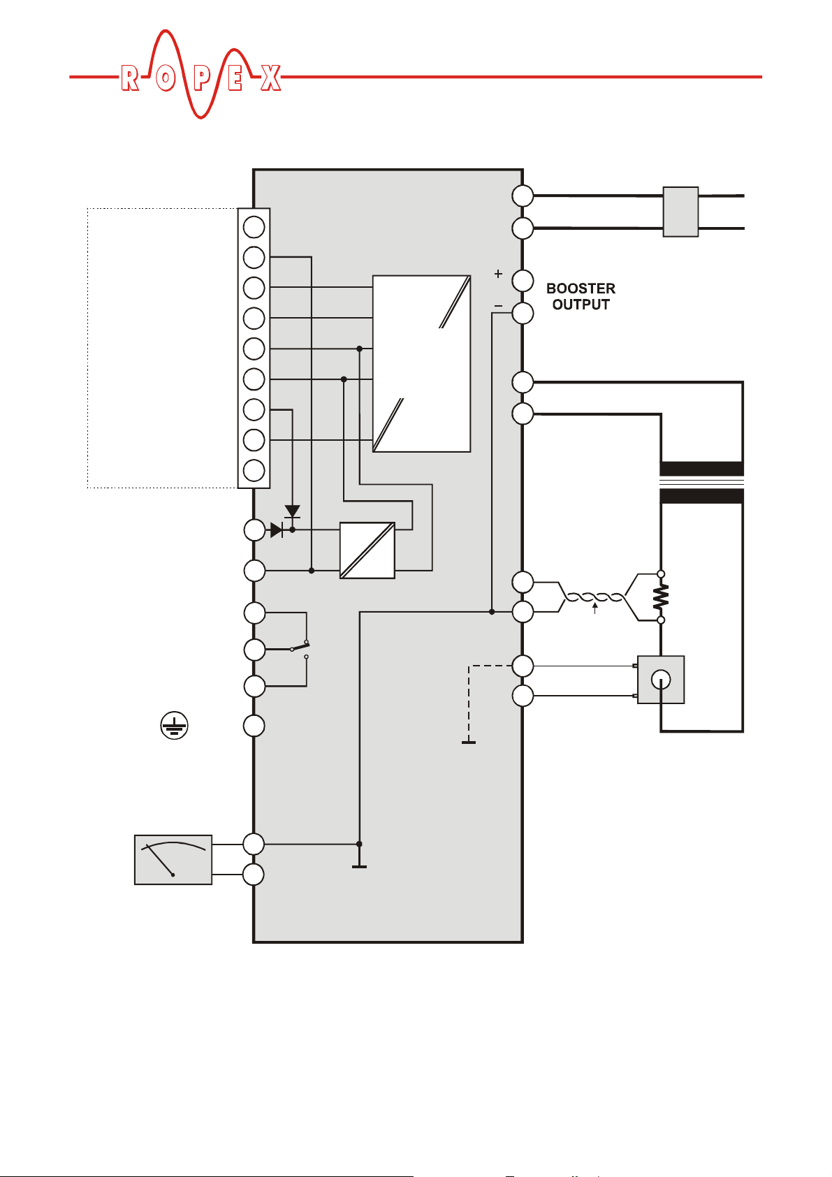
8.7 Wiring diagram with booster connection
Line filter LF-xx480
Booster
production
up to
transformer
twisted
Impulse
prim.
sec.
R
Must be grounded
+0...10VDC
°C
ANALOG
OUTPUT
18
17
January 2006
(Internnal ground)
grounding allowed!
0V
(Internnal ground)
grounding allowed!
RES-406 Page 15
Current transformer
 Loading...