

Ropex Resistron RES-242, Resistron RES-241 User Manual
09.02
RESISTRONRESISTRON
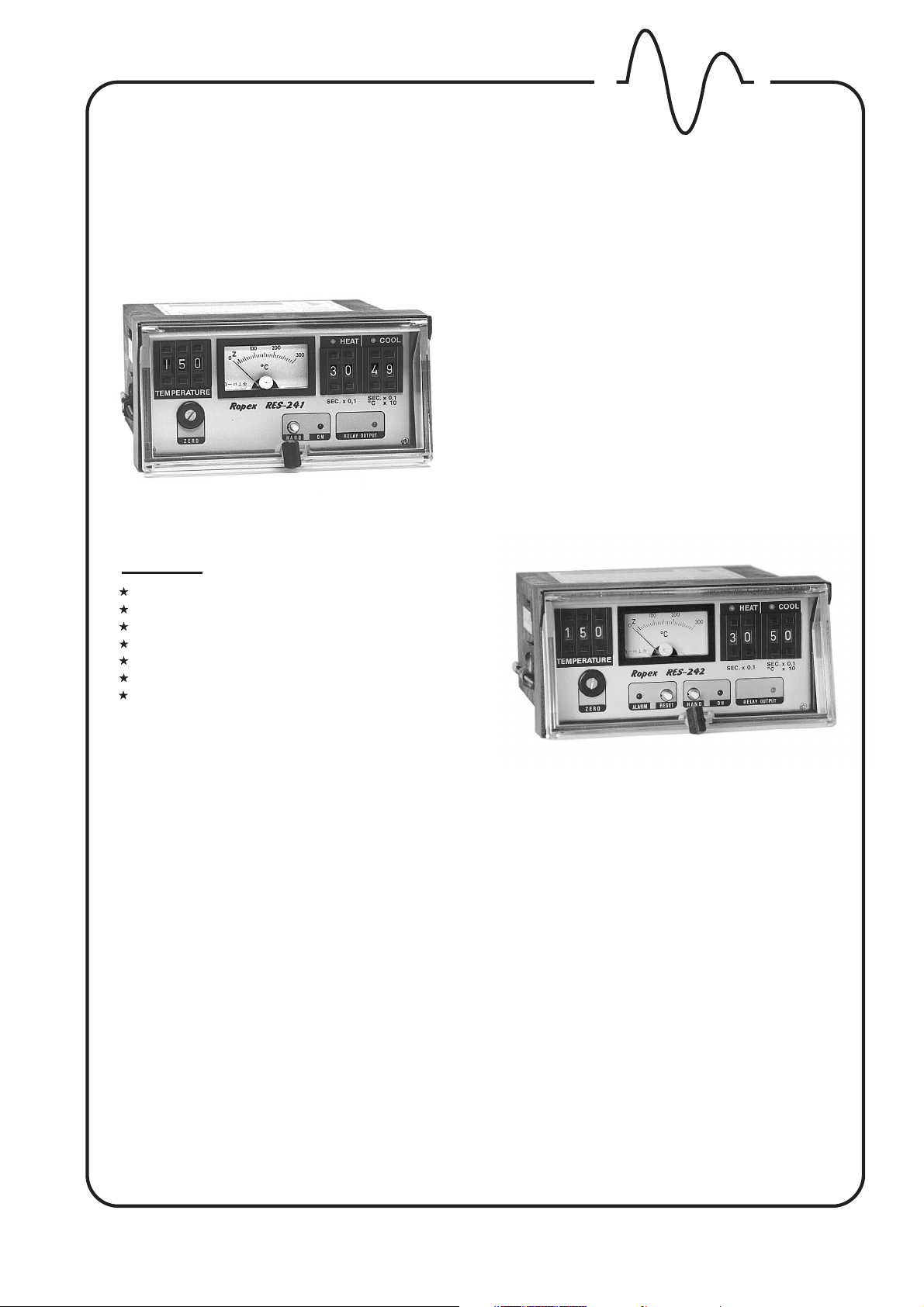
RES-241RES-241
without Alarm
ROPE X
ROPE X
INDUSTRIE
TEMPERATURE CONTROLLER
FOR HEATSEAL BANDS
TO SEAL PLASTIC FILMS
-
ELEKTRONIK
FEATURES
Designed for Easy Mounting on the Control Panel
Analog Temperature Meter
Integrated Heat Sealing and Cooling Programs
Numerous Programming Functions
Easy Installation and Operation
Built in Timers
Preferred for General Applications
TABLE OF CONTENTS
1. APPLICATION AND SHORT DESCRIPTION
2. FUNCTIONS OF THE RES-241/242
2.1 Control Function
RES-242RES-242
with Alarm
4. PROGRAMMING OF THE TIMING FUNCTIONS
5. EXAMPLE
6. WIRING DIAGRAM
2.2 Zero Calibration
2.3 Start-Function
2.4 Cycle Timing
2.5 Alarm Function
2.5.1 Alarm Signal
2.5.2 Reset
3. CONTROLS AND INDICATORS
Industrie - Elektronik GmbH.Gansäcker 21.D-74321 Bietigheim-Bissingen
ROPE X
ROPE X
Telefon (07142) 7776-0.Telefax (07142) 7776-19
7. OPERATING INSTRUCTIONS
8. HEATSEAL ELEMENT
9. HEATING IMPULSE, TIMING
10. OUTLINE DIMENSIONS
11. SPECIFICATIONS
12. GENERAL INSTALLATION INSTRUCTIONS
.

ROPE X
ROPE X
1. APPLICATION AND SHORT DESCRIPTION
Page 2
As all other , this unit is used to control
the temperature of heating elements (heatseal bands,
beaded bands, cutting wires, etc.) by monitoring the
resistivity of the heating elements. Precision
measurement together with high response produces
perfect temperature control during the film sealing
processes. With a correctly installed system, the
temperature is controlledwithan accuracy of±3%.
By changing settings, this controller can be used to
control heating elements with a range ofresistances from
a few milliohmsto several ohms. Therefore, this universal
controller may be used in a variety ofgeneral applications
for controlling theheatseal elements in:
vertical and horizontalf/f/s machines
pouch filling andsealing machines
film wrapping machines
pouch making machines
group packaging machines,etc.
The controller, have all the known
functions of the RES-200 series, plus two digital timers,
sealing time and cooling time. This eliminates additional
external usage of timers to control heat impulse timing
and jaw action.
This additional feature makes the controller very suitable
for use in:
RES controllers
RES-241 / 242,
As shown in Section 5, a complete sealing station can be
controlled with this controller without using additional
electrical components.
All parameters related to the sealing phase, like time and
temperature, can easily be selected by use of the digital
switches on thefront panel of theunit.
The desired values are entered according to the
appropriate units, i.e. and/or .
Numerous functional sequences can be programmed
with the dip switches mounted on side of the controller.
This allows the user to select the best program for any
specific heatsealing process.
Processes that are primarily temperature dependent can
be programmed, e.g. closing of the jaw only after full
sealing temperature has been reached; or opening of the
jaws only after the cooling to a pre-determined
temperature has beenreached.
(see Section 4:Timing Functions Programming).
The cycle sequence can beobserved during operation by
means of the analog temperature meter and the LED´s
for heating andcooling.
°C sec
hand operated andtable top machines
heatsealing sealing presses
L-sealers
2. FUNCTIONS OF THE RES-241 / 242
2.1
The controller operates in two different modes: monitoring or controlling.
If there is , the controller will only
monitor the resistance of the heating element without
raising the temperature. Resistance monitoring is
accomplished by means of short low power pulses every
10 cycles of the line frequency. It is in this mode that the
"Z" calibration is performed. In the monitoring mode, the
"ON" LED blinks red. When a START signal is applied,
LED "ON" becomessteady state red.
no START signal
CONTROL FUNCTIONS
Both the and controllers are identical
with the exception ofthe "alarmfunction" that is contained
only in theModel RES-242.
The controller then goes into the regulating mode and
increases the temperature of the heating element to the
desired set point as rapidlyas possible.
The maximum secondary voltage is initially supplied to
the heating element and then subsequently reduced by
the phase control as the preset maximum temperature is
approached.
A high sampling rate together with virtually instant
feedback gives the controller an instantaneous response
capability.
RES-241 RES-242
ROPE X
ROPE X
INDUSTRIE - ELEKTRONIK GmbH

ROPE X
ROPE X
Page 3
Control Function (Continuation)
Current
Temp.
Start
full
heat current
20°C
OFF
sampling sampling
regulating mode
set point
reduced
heat current
ON
OFF
temperature display
controller
actual
temperature
sampling
pulses
Start
2.2
ZERO calibration is the adjustmentof thecontroller tothe
resistance of thecold heatseal element.
This calibration must be performed with the heatseal
band at room temperature. The hand of the analog
temperature meter is set to "Z" by turning the "ZERO"
adjustment trimmer with the heatseal element at ambient
temperature and the controller in the monitoring mode.
("Z" = 20°C/68°F). After calibration the hand should rest
quietly at "Z".
2.3
A heating cycle is initiated with the start function. The
controller then switches from the monitoring mode to the
regulating mode, and concurrently starts the timing
cycles. The START signal can be given in three different
ways:
by pressing "HAND"on the front panel
by closing thecircuit between terminals 2 and 7,
with potential freecontact.
by supplying 24VDCto Terminals 3 and 4
A feature prevents the overheating of the
"START-Lock"
heating element when the controller is improperly
calibrated, set belowthe "Z" point.
Should this occur, the RES-241 controller will not accept
the START signal, while the RES-242 will go into "ALARM"
and shut down.
ZERO CALIBRATION
START-FUNCTION
Proper operation depends upon the accurate calibra-tion
of the system. Because the resistance of the heatseal
element may very depending upon its precise length and
cross-section, the calibration ("Z" point) must be checked
and reset after each change or replacement of the
heatseal element.
(see Sect. 8, "Heatseal Element" and Sect. 7, "Operating
Instructions")
NOTE - When using new heating elements:
After a few temperature cycles the resistance of the
element will be reduced, the calibration may no longer be
correct. When this occurs, allow the heating element to
return to ambient temperature and reset the meter to "Z"
by using theZero Trimmer.
START ENABLE
when needle is
below zero
Mechanical zero adjustment. Do not move!
Z
0
100 200
300
°C
ROPE X
ROPE X
INDUSTRIE - ELEKTRONIK GmbH

ROPE X
ROPE X
Page 4
Functions of the RES-241/242 (Continuation)
2.4
Heating and cooling cycle time follow each other.
Depending upon the program selected by use of the DIP
switch, the either starts with the "START"
signal or when the heating element reaches the pre-set
temperature.
(see Section 4"Timing Functions Programming").
The always starts at the end of the
heating cycle. The maximum time duration for heating or
cooling is 9.9 seconds. Depending upon the program
selected, the duration of the cooling cycle may be set to
heating time
cooling cycle time
2.5
2.5.1
To increase the reliability of operation and to assure
adequate seals, the RES-242 controller contains a
comprehensive monitoring system that will send an
alarm signal (LED "ALARM" will turn red) and activate the
alarm relay when:
CYCLING TIMING
ALARM FUNCTION (RES-242 only)
ALARM SIGNAL
be a funtionof time or temperature.The cooling cycle may
be setto end when a pre-set temperature is reached, that
means that the relayK1 will drop out when the temperature drops below the pre-select level. The selection is done
by means of the 2 position digital selector switch in °C x 10
in increments of10 degrees.
EXAMPLE:
To assure a trouble free "ZERO" calibration, functions e)
and f) willonly activate after thestart signal is given.
Other reasons foran ALARM signal are:
Selection 08 = 80 °C
Selection 12 = 120 °C
a) the heatseal elementbreaks, or any discontinuityin
the secondary circuitoccurs.
b) ONE of theheatseal elements breaks whentwo
bands are mountedparallel.
c) A short circuitoccurs at the heatsealelement
d) Any discontinuity occursin the monitoring wiringof
the heatseal elementor the current transformer.
e) Any overheating ofthe heatseal element by20%
above the controller´soperating temperature range
f) "Z" point isincorrectly set.
(see "START Function" and "StartBlock")
2.5.2
The controller can be reset - after the cause of the alarm
has beencorrected - by pushing the "RESET" button or
by turning offthe main power byat least 1 second.
RESET
incorrect programming of DIP switchesin the
for U voltage selection.
2
improper position ofthe frequency jumper.
improper power supplyvoltage.
internal malfunction.
In the case of an alarm, the LED "ALARM" will turn red, the
controller output will be disabled, and the ALARM relay
will close betweenterminals 5 and 6.
Taste "RESET" oder Abschalten der Netzspannung
für mind. 1 sec und Wiedereinschalten.
ROPE X
ROPE X
INDUSTRIE - ELEKTRONIK GmbH

ROPE X
ROPE X
3. CONTROLS AND INDICATORS
Page 5
Preset Temperature
Digital Switch in °C
max.299°C
DIP Switches
ON
12345 678910
for Programming of
Sealing Process
14
DIP Switch
to select U
3
2
15
Temperature Meter
in °C
"Z" pt. is at 20 °C
1
LED RED for
Sealing Time
8
Select Sealing
Time
in sec x 0,1
9
11
LED GREEN for
Cooling Time
10
Select Cooling
Time
in Sec. x 0,1.
max.9,9sec
or depending upon
the DIP switch
programming
Select Cooling
13
Jumper for
Frequency Selection
2
7
6
4
5
12
10 Turn "ZERO" Trimmer
for
setting Calibration to "Z"
LED is RED when
on RES-242 only
START "HAND" BUTTON
will start controller with a
full timing cycle
ROPE X
ROPE X
LED RED, blinks in
monitoring mode,
remains when
controller starts
(heating cycle)
LED YELLOW
Indicates status of
K1 Output Relay;
ON when relay is
closed
INDUSTRIE - ELEKTRONIK GmbH
 Loading...