

Page 1
RESISTRON
GB
PD-3 / PD-5
(KD, P-3/5)
Operating
Instructions
RESISTRON/CIRUS temperature controllers are
available in several different variants. Some of these
controllers allow the set point to be selected by means
of an externally connected potentiometer.
ROPEX offers PD-3 (300 °C range) and PD-5 (500 °C
range) precision potentiometers, which are optimally
tuned to the controllers, for this purpose.
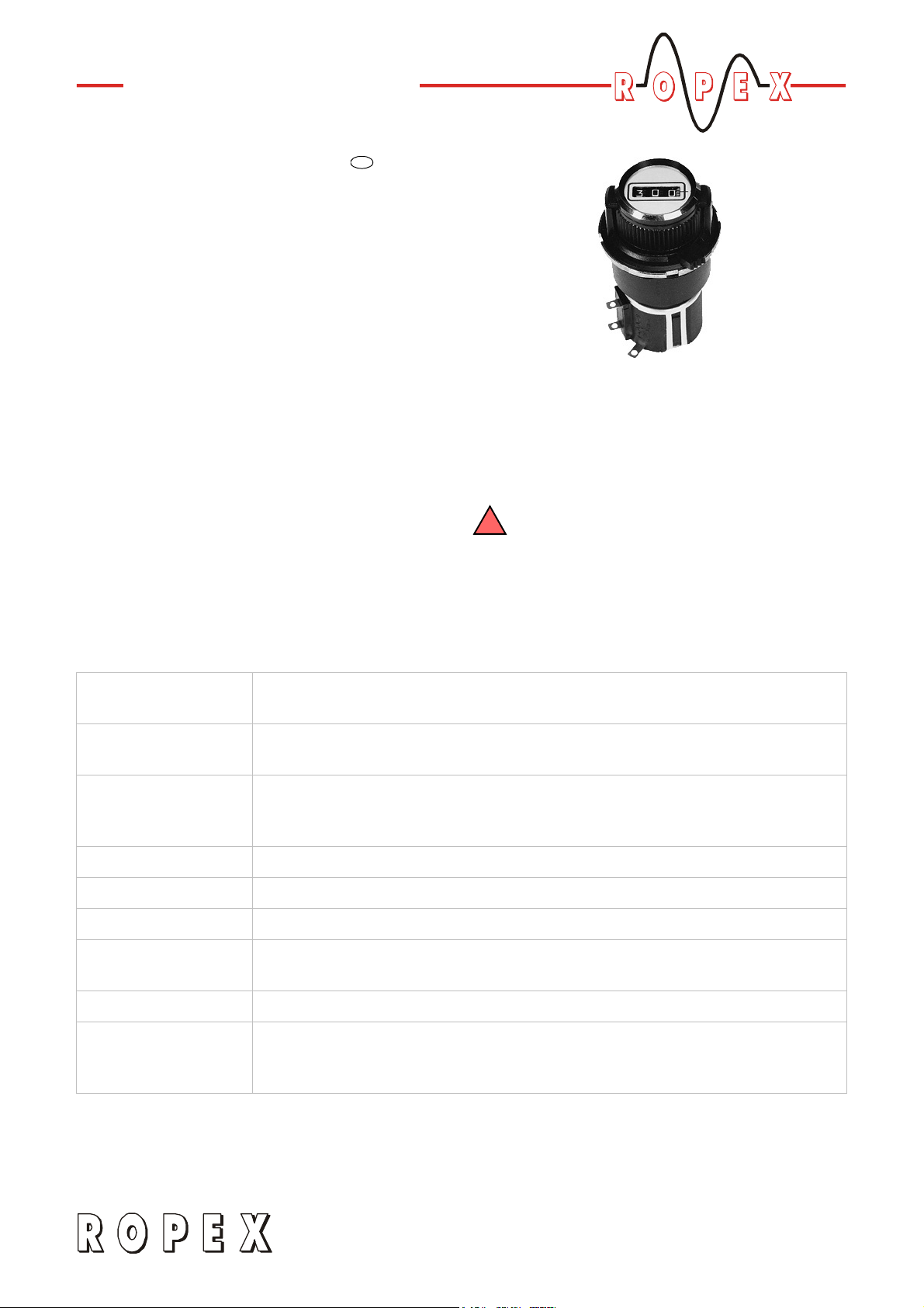
These potentiometers permit the SET temperature to
be adjusted exactly with the help of the digital display in
the window of the fine control knob. The number that
appears on the display corresponds to the SET
temperature in °C.
The PD-3 (or PD-5) precision potentiometer consists of
a P-3 (or P-5) setting potentiometer and a KD fine
control knob with digital display.
The information provided in the latest
!
version of the controller documentation shall
be heeded when using the PD-3 or PD-5
potentiometer, in order to avoid malfunctions.
Technical data
Type of construction Precision potentiometer with a digital fine control knob,
for front panel mounting
Resistance,
power
Set point indication
(KD knob)
PD-3 (P-3): 2kohms; 3 turns; 2.0W
PD-5 (P-5): 2kohms; 5 turns; 2.0W
Window with digital display
PD-3: 0…300
PD-5: 0…500
Accuracy Linearity +-0.15 %
Degree of protection Front (KD knob): IP20; back (P-x potentiometer): IP00
Insulation voltage 1000VAC, 1 min.
Ambient
temperature
Weight Approx. 60 g
Connecting cable
Type / cross-sections
3.11.03
+5…+45°C
Flexible; 0.2…1.5 mm² (AWG 16…12)
Connection by means of soldering lugs
Note: Rigid cables break easily !
Page 2
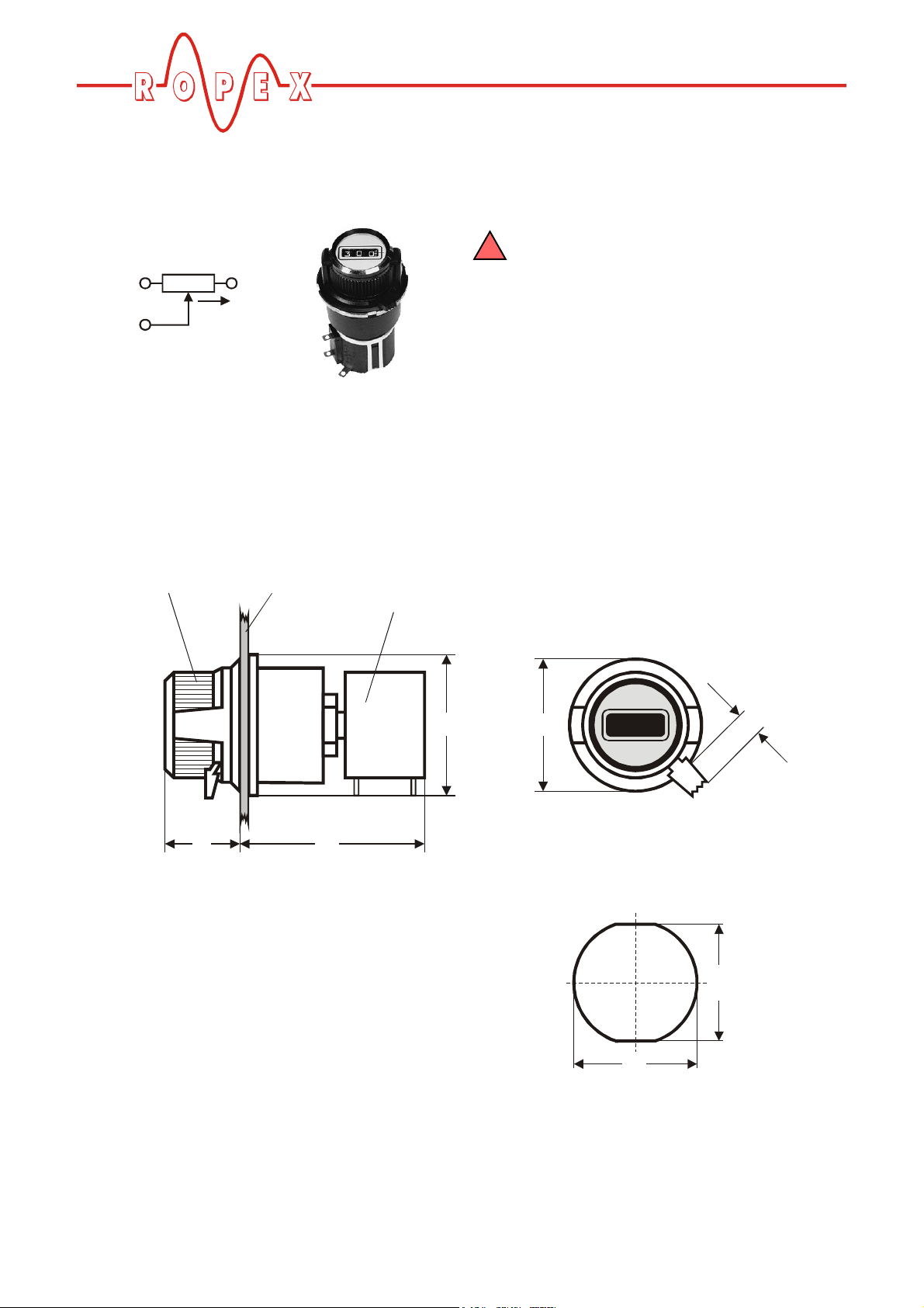
Wiring diagram
1
cw
2
Dimensions
When you connect the potentiometer, please
!
note the direction of rotation, in order to
3
3
1
2
avoid malfunctions.
KD knob
Front panel Potentiometer
17 42
P-3 / P-5
32
30
0 0 0
Front panel cutout
3
26.5
Page 2 PD-3 / PD-5
28
Page 3

Installing the PD-3/-5 (assembly of P-3/-5 and KD)
KD knob
Proceed as follows to assemble/install the
potentiometer:
1. Make a cutout in the front panel (ª section
„Dimensions“ on page 2).
2. Insert the KD fine control knob
cutout and screw it tight with the nut
3. Screw the lock washer
potentiometer with the two hexagon nuts
4. Turn the potentiometer shaft counterclockwise as
far as the minimum resistance setting (0 ohms).
Note: This is NOT necessarily the same as the shaft
end stop!
c into the front panel
e.
f onto the P-3/-5
g.
Front panel
cutout
5. Turn the dial of the KD fine control knob
display indicates "000". Loosen the locating screw
Potentiometer
P-3 / P-5
c until the
d on the underside of the knob.
6. Insert the shaft of the P-3/-5 potentiometer into the
KD knob from behind. The lock washer
snap into the lugs on the KD knob. Then tighten the
locating screw
The shaft of the P-3/-5 potentiometer and the
!
dial of the KD fine control knob must remain
absolutely stationary until the installation is
complete. If they are moved, the display on the
knob will deviate from the value set with the
potentiometer.
d again.
f must
How to order
Precision potentiometer with digital fine control knob
PD-3 (resistance 2 kohms, display 0…300): Art. No. 881103
PD-5 (resistance 2 kohms, display 0…500): Art. No. 881105
Precision potentiometer (as spare part)
P-3 (resistance 2 kohms, 3 turns): Art. No. 881003
P-5 (resistance 2 kohms, 5 turns): Art. No. 881005
Fine control knob with digital display (as spare part)
KD: Art. No. 881113
PD-3 / PD-5
 Loading...