

RESISTRON
GB
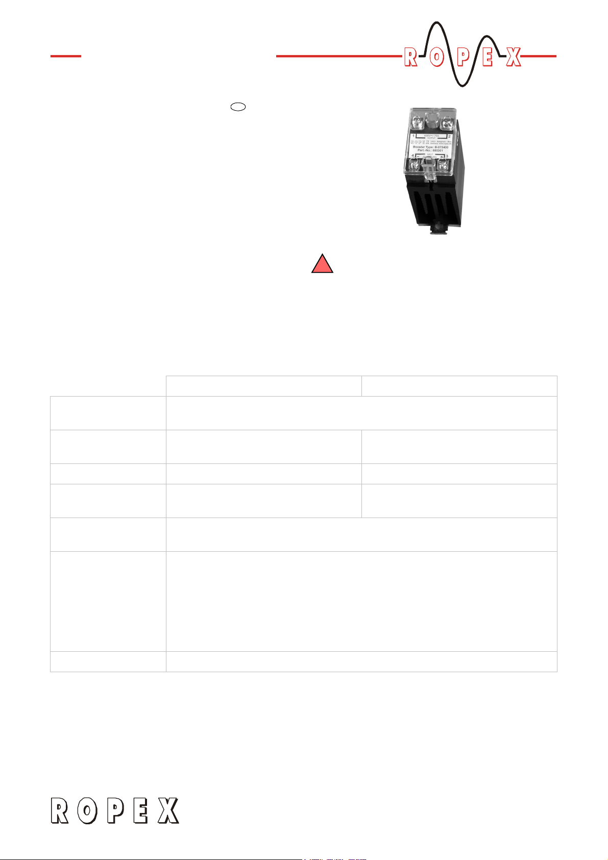
Booster
B-xxx400
Operating
Instructions
RESISTRON/CIRUS temperature controllers can
process very high peak and continuous currents on the
primary side as standard. External switching amplifiers
(Booster types B-075400 and B-100400) can be
supplied for higher currents.
The information provided in the latest
!
version of the controller documentation and
in the ROPEX Application Report should be heeded
when using a B-xxx400 Booster, in order to avoid
malfunctions.
Technical data
B-075400 B-100400
Type of construction Switching amplifier with heat sink for installation in the electrical cabinet
Snaps onto a standard top hat rail (DIN TS35 rail, 35mm) acc. to DIN EN 50022
Size Dimensions: 46 x 67mm
Depth: 134 mm (incl. cover)
Weight Approx. 0.5 kg Approx. 1.1kg
Load current
Terminals 1+2
Load voltage
Terminals 1+2
75A peak current
25A continuous current
115VAC - 15% … 415VAC + 10%
(98…456VAC)
Dimensions: 72 x 75 mm
Depth: 142mm (incl. cover)
100A peak current
50A continuous current
Control
Terminals 3+4
Degree of protection IP00
18.1.08
RES-401/-402: Not available
RES-403/-407/-408/-409: Via modification 26 (MOD 26)
RES-406: As standard, refer to controller documentation
RES-415/-420/-440/-445: As standard, refer to controller documentation
LPT-640: As standard, refer to controller documentation
UPT-606: As standard, refer to controller documentation
UPT-640: As standard, refer to controller documentation
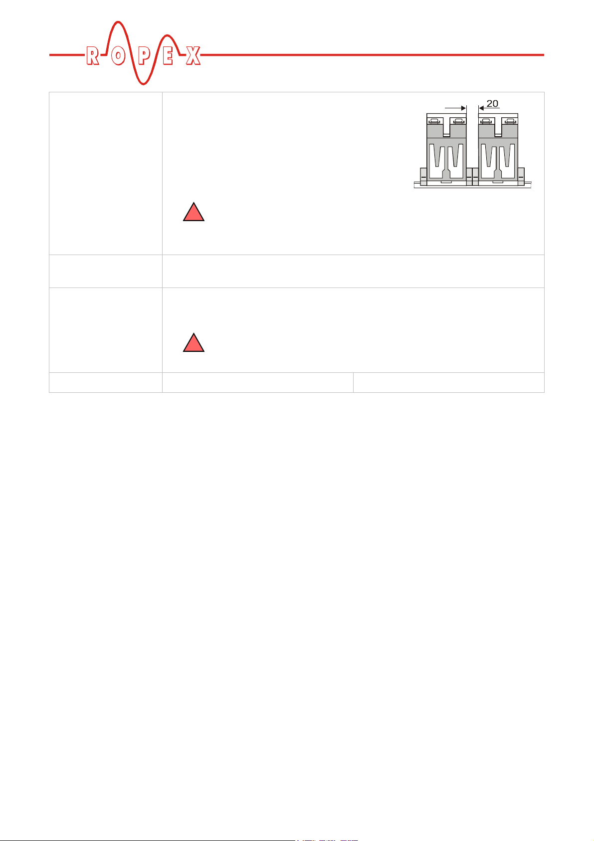
Installation If several switching amplifiers are installed on one
top hat rail (DIN TS35 rail), a clearance of at least
20mm should be allowed between them.
The moving clip required for fastening must be
facing down for mounting on a horizontal top hat
rail.
For a sufficient air cooling of the switching amplifier the mounting on
!
a horizontal top hat rail - assembled on a upright subplate - is allowed
only. Other mounting directions might cause malfunctions due to an
overheating of the switching amplifier.
Ambient
temperature
Connecting cables
Type / cross-sections
Power dissipation max. 40 W max. 70W
Terminals 1+2 (load circuit): Screw terminals, diameter 4.1 mm
Terminals 3+4 (control): Screw terminals, diameter 3.5 mm
The connection cable between switching amplifier (terminals 3+4) and
!
temperature controller shall not exceed the length of 1meter. Longer
cables might cause malfunctions.
+5…+45°C
Page 2 Booster
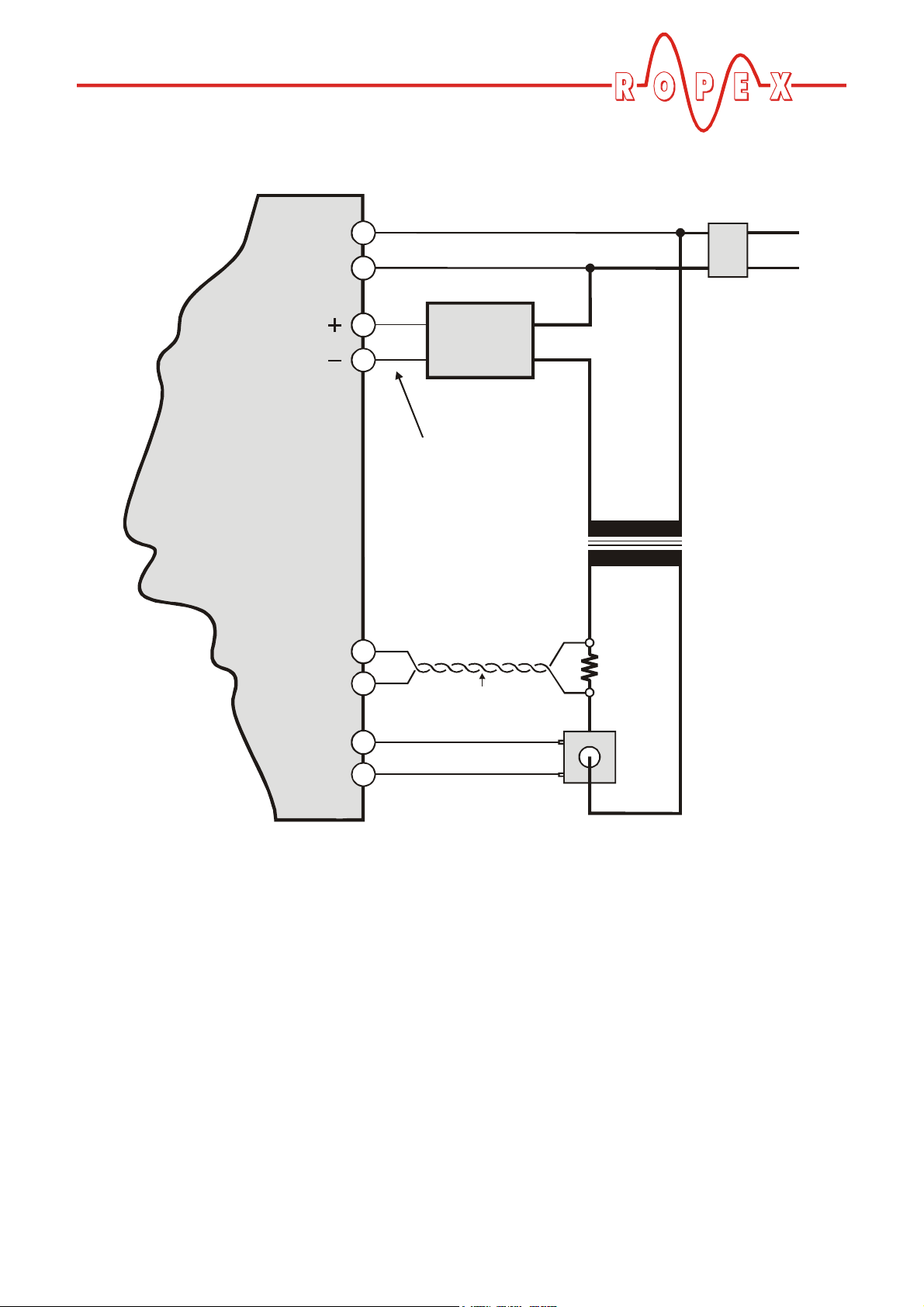
Wiring diagram
Line filter LF-xx480
Booster output
RESISTRON/
CIRUS
temperature
controller
Line
U
LINE
13
Booster
IN OUT
24
Max. length: 1m
U
1
prim.
Impulse
transformer
U
2
sec.
R
Twi sted
R
band
Heatsealing
I
R
Current transformer
PEX-W2/-W3
Booster
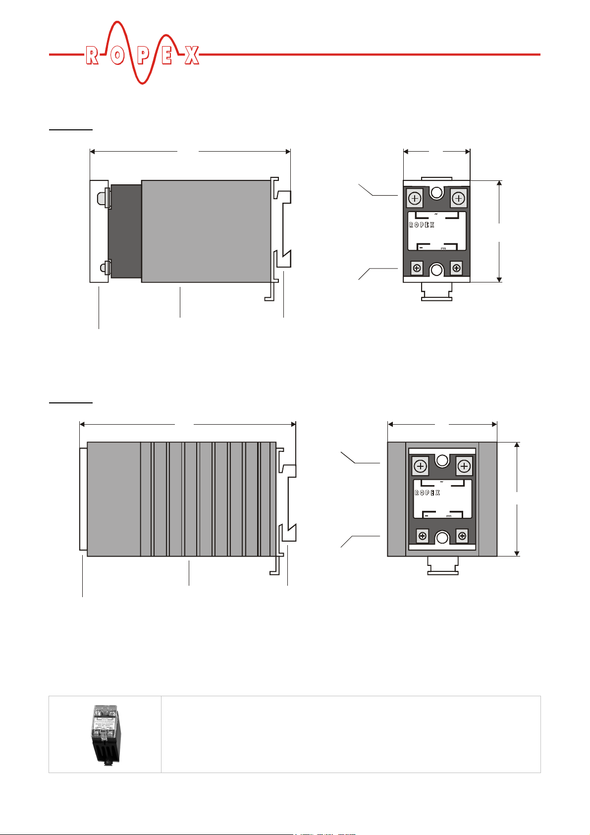
Dimensions
B-075400
B-100400
Cover
134
Booster with
heat sink
142
Adapter for
top hat rail mounting
Terminals 1+2
(load circuit)
Terminals 1+2
(load circuit)
Terminals 4+3
(control)
46
400V / 75A
1
OUTPUT
74321 Bieti gheim - Biss .
Germany. www.ropex.de
Booster Type: B-075400
Part.-No.: 885301
INPUT
4
3 - 32V
72
2
67
3
+
Cover
How to order
Terminals 4+3
(control)
Booster with
heat sink
Adapter for
top hat rail mounting
Switching amplifier (Booster)
B-075400 ( 75A, 400 VAC): Art. No. 885301
B-100400 (100 A, 400VAC): Art. No. 885304
400V / 100A
1
OUTPUT
74321 Bietigheim - Biss.
Germany. www.ropex.de
Booster Type: B-100400
Part.-No.: 885304
INPUT
4
3 - 32V
2
75
3
+
Page 4 Booster
 Loading...