

Page 1
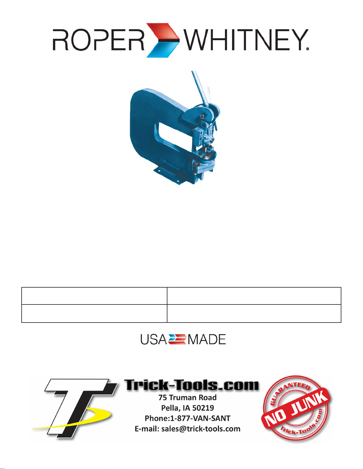
MODELS NO. 1 18, NO. 218
DEEP THROA T HAND PUNCH
OPERA TION, P ARTS & MAINTENANCE MANUAL
Model: Purchased From:
Serial #: Date Received:
Page 2

FOREWORD
This manual has been prepared for the owner and operators of Roper Whitney No. 1 18 and No. 218
Deep Throat Hand Punch. Its purpose, aside from operations instructions, is to promote safety through
the use of accepted operating procedures. Read all instructions thoroughly before operating the hand
punch.
Also contained in this manual is the parts list for your hand punch. It is recommended that only Roper
Whitney or factory authorized parts be used as replacements.
Warr anty Statement:
3 YEAR LIMITED WARRANTY
Roper Whitney (“Manufacturer”) warrants, commencing with the date of shipment to first end-user
(“Customer”) and for a period of thirty-six (36) months thereafter, all machinery and parts manufactured
by Manufacturer to be free of defects in workmanship and material. This warranty remains in force for
the above time period only if all of Manufacturer’s operational procedures are followed and
recommended maintenance is performed. If, within such warr anty period, any machinery or parts
manufactured by Manufacturer shall be proved to Manufacturer’s satisfaction to be defective, such
machinery or parts shall be repaired or replaced, at Manufacturer’s option. All warranty claims are made
F.O.B Manufacturer’s plant, providing such machinery or parts are returned freight prepaid to
Manufacturer’s plant or designated service center for Manufacturer’s inspection. All failed parts or
components must be returned to Manufacturer prepaid for inspection before credit will be issued for new
parts or components. Manufacturer’s obligation hereunder shall be confined to such repair or replacement
and does not include any charges, direct or indirect, for removing or replacing defective machinery or
parts. No warranty shall apply to machinery, or parts or accessories, which ha ve been furnished, repaired,
or altered by others so as, in Manufacturer’s judgment, to affect the same adversely or which shall have
been subject to negligence, accident or improper care, installation, maintenance, storage, or other than
normal use or service, during or after shipment. No warranty shall apply to the cost of repairs made or
attempted outside of Manufacturer’s plant or designated service center without Manufacturer’s
authorization. No warranty shall apply with respect to machinery or part not manufactured by
Manufacturer, including but not limited to motors, accessories, electrical and hydraulic components, if such
machinery or part is subject to warranty by the manufacturer of such machinery or part. No warranty
claims by Customer will be honored with respect to any machinery or part from which the name and date
plate has been removed or is otherwise no longer located or exhibited on such machinery or part. THE
FOREGOING WARRANTIES ARE IN LIEU OF ALL OTHER WARRANTIES EXPRESSED OR IMPLIED,
INCLUDING, BUT NOT LIMITED TO, ANY IMPLIED WARRANTY OF MERCHANTABILITY AND IMPLIED
WARRANTY OF FITNESS FOR A PARTICULAR PURPOSE. MANUFACTURER SHALL NOT BE SUBJECT TO
ANY OTHER OBLIGATIONS OR LIABILITIES WHATSOEVER WITH RESPECT TO MACHINERY, PARTS,
ACCESSORIES, OR SERVICES MANUFACTURED OR FURNISHED BY IT OR ANY UNDERTAKINGS, ACTS,
OR OMISSIONS RELATING THERETO. UNDER NO CIRCUMSTANCES SHALL MANUFACTURER BE
LIABLE FOR ANY CONSEQUENTIAL OR OTHER DAMAGES, EXPENSES, LOSSES, OR DELAYS HOW SO
EVER CAUSED.
THERE ARE NO WARRANTIES THAT EXTEND BEYOND THE DESCRIPTION ON THE FACE HEREOF.
Note: Consumable tooling is not covered under the 3 year manufacturer’s warranty.
RETURN OF THE PRODUCT REGISTRATION CARD FURNISHED WITH THE PRODUCT IS NECESSARY TO OBT AIN
WARRANTY COVERAGE THEREON. CARD MUST BE FULLY COMPLETED , SIGNED BY THE PURCHASER, AND IF
APPLICABLE, SIGNED BY THE DISTRIBUTOR. RETURN REGISTRATION CARD TO:
Page 3
SAFETY INSTRUCTIONS
FOR MAXIMUM OPERA T OR SAFETY DO:
1. Read and understand this manual.
2. Use only punches and dies marked with a W or R-W designed for this tool.
3. Be sure you punch within the four ton capacity of this tool. T ype and thickness of material versus
final hole size will give you this tonnage.
4. Wear safety glasses.
FOR MAXIMUM OPERA T OR SAFETY DO NOT:
1. Use punches and dies that are chipped or dulled.
2. Punch over capacity of the tool.
3. Nibble. Punch a full hole not a half hole as punch may contact die.
SPECIFICATIONS
118* 218
Depth of Throat 7” 12”
Die Space, Punch in Highest Position 3/4” 3/4”
Height of Throat, with Work Table 2 3/4” 2 3/4”
Height of Throat, without Work T able 4 1/2” 4 1/2”
Length of Stroke 3/4” 3/4”
Slug Hole Clearance 2 1/4” 2 1/4”
Diameter of Punch Shank Hole in Ram 1” 1”
Floor Space Required (Floor Model) 23” W x 14” D x 37”H
Weight, Bench Model 103 lbs. 134 lbs.
Weight, Floor Model 200 lbs. 231 lbs.
Weight, Work Table 7 lbs. 7 lbs.
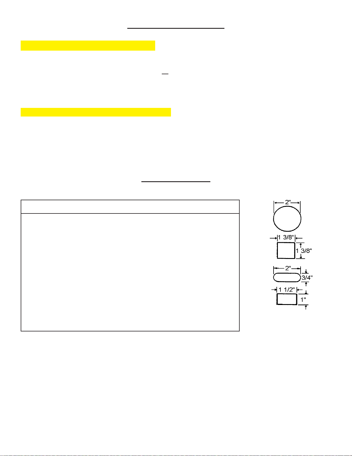
Largest punches and
* No. 1 18 is obsolete but parts are common with the No. 218.
Standard equipment includes: one L8 Punch Holder , one No. 20 Die Adaptor , one No. 40 Die Adaptor,
one 1 18 - 2 3/4” Die Shoe, S tripper Arms, one A S tripper Plate, S tandard 1/2” Round Punch and Die.
No substitutions on standard equipment.
dies deepthroat hand
punch will accommodate
- 3 -
Page 4
DIMENSIONS
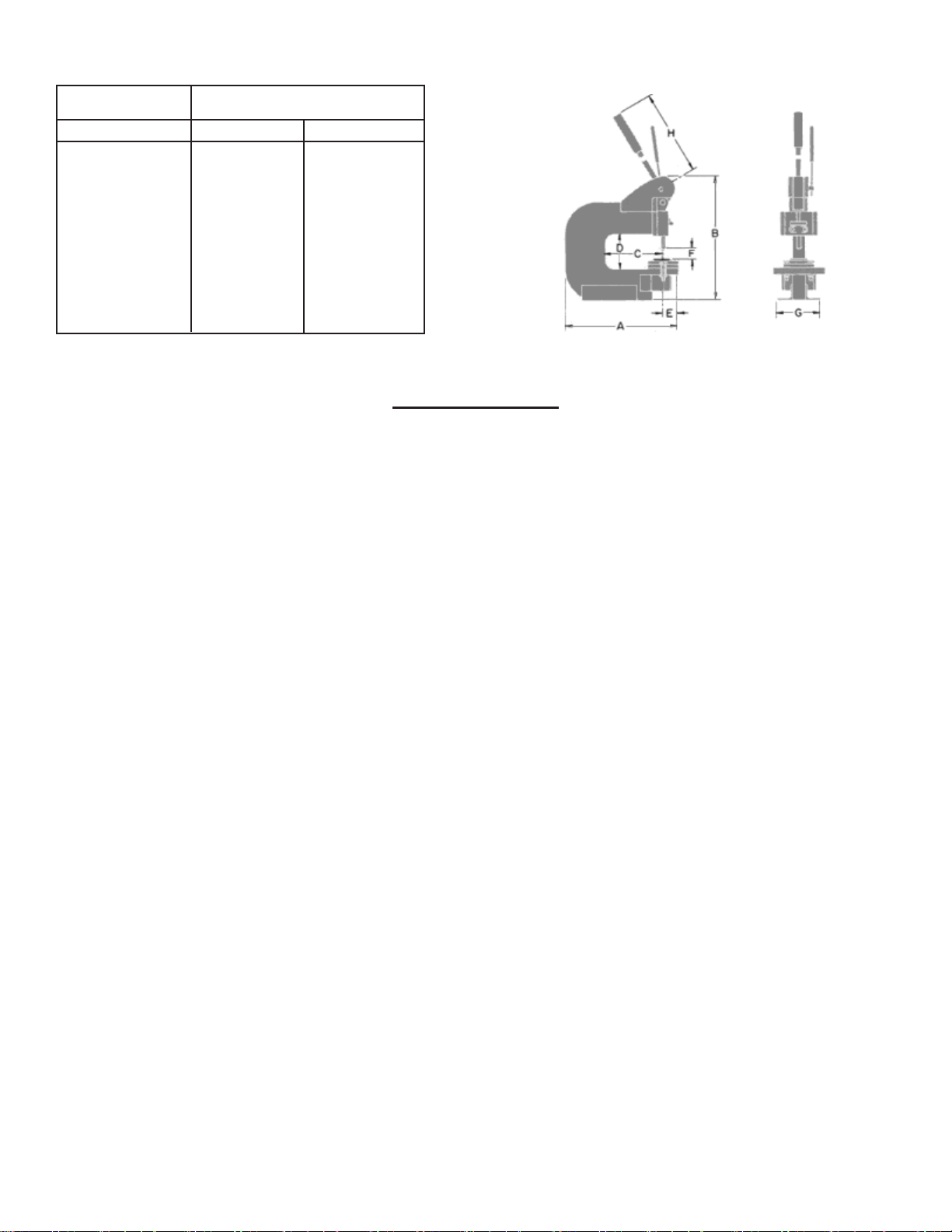
Reference No. 218
IN. MM
A 21 1/2 546.1
B 17 5/8 447.68
C 12 1/4 31 1.15
D 4 1/2 1 14.3
E 2 1/16 52.39
F 3/4 19.05
G 5 127
H 24 609.6
INSTRUCTIONS
CARE: Oil ram slide, cam and punch point occasionally.
OPERA TION: To change dies loosen two die shoe bolts and remove die shoe. Loosen die shoe set
screw and push upward on die or die adaptor. If using No. 28 2-3/4 style die insert desired size of die in
die shoe and tighten die shoe set screw. If 20 or 40 style dies are used, insert die into die adapto r,
tighten die adaptor set screw, place in die shoe and tighten die shoe set screw.
Lower punch into die, check clearance and tighten die shoe bolts.
To change punches with die shoe removed, loosen punch retainer set screw and both punch retainer
nuts. Remove punch or L8 punch holder. (No. 28 punches insert directly into ram and No. 8 style
punches are inserted in L8 punch holder and then into ram.) When inserting punch or punch holder into
ram be sure flat on shank is facing front of ram. Tighten punch retainer nuts and set screw .
Install proper stripper plate for punch size being used. Place a flat object (1/4” bar stock) on die and
slide stripper plate down until it rests on the bar . Tighten stripper arm bolts and remove bar.
Punches should not enter die more than 1/16”. To adjust loosen eccentric pin nut, adjust ram up or down
with eccentric pin handle and tighten eccentric pin nut when desired adjustment is attained.
Two gib shims are between each gib and the frame face plate. Remove one or both shims on each side
of ram to compensate for wear.
If necessary to replace the roller bearing place bearing with mounting plug in proper position. Drive the
roller bearing pin through the frame and bearing forcing the mounting plug out of bearing and discard.
Tighten roller bearing pin set screw.
- 4 -
Page 5
ACCESSORIES
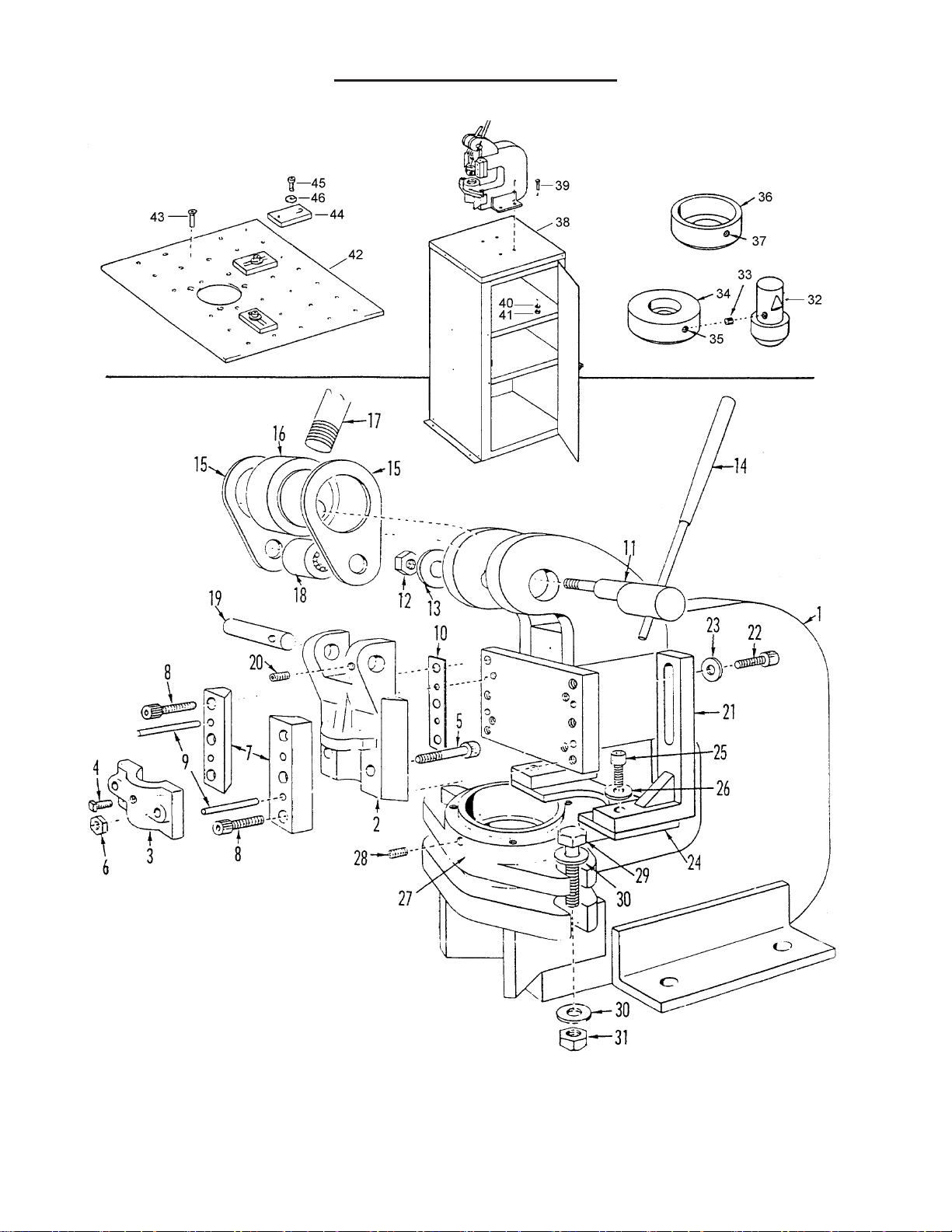
NOS. 118, 218 PARTS LIST
- 5 -
Page 6

NOS. 118, 218 PARTS LIST
ITEM PART NO. PART NAME NO. OLD
NO. REQ. P ART NO.
1 731 140019 Frame for No. 1 18 (7” Depth Throat) 1 118-1
1 731 140018 Frame for No. 218 (12” Depth Throat) 1 218-1
2 231940005 Ram with Punch Retainer 1 1 18-2
3 731600057 Punch Retainer 1 1 18-2-1R
4 633012131 Punch Retainer Set Screw (5/16-18 x 3/4) 1 WS 615
5 731650275 Punch Retainer Screw 2 1 18-17
6 600023026 Punch Retainer Nut (Acorn 5/16-18) 2
7 731400020 Gibs 2 118-4
8 611012133 Gib Bolt (SHC 5/16-18 x 1) 6 WS 525
9 600043253 Gib Taper Pin (#5 x 1 1/4) 4 WS 1492
10 731720027 Gib Shims 4 118-18
11 731160022 Eccentric Pin 1 118-6
12 643023007 Eccentric Pin Nut (Hex Full 1/2-13) 1 WS 1356
13 679033107 Lock Washer (1/2) 1 WS 1731
14 731000281 Eccentric Pin Handle 1
15 731240023 Side Links 2 118-7
16 731210021 Cam 1 118-5
17 731460024 Operating Handle 1 1 18-8
18 240940006 Roller Bearing 1 100-17
19 731160025 Roller Bearing Pin 1 118-13
20 600325905 Roller Bearing Pin Set Screw (1/4-20 x 1/2) 1 WS 700
21 231940004 Stripper Arms (per set) 1 118-9
22 611012133 Stripper Arm Bolts (SHC 5/16-18 x 1”) 4 WS 525
23 678033104 Stripper Arm Bolt W asher (Flat 5/16) 4 WS 1703
24 331200500 A6 Stripper Plate (Punch Size to 1/2”) 1 118-14
24 331201000 B6 Stripper Plate (Punch Size to 1”) 1 118-10
24 331202000 C6 Stripper Plate (Punch Size to 2”) 1 1 18-15
25 611012131 Stripper Plate Bolt (SHC 5/16-18 x 3/4) 2 WS 524
26 678033104 Stripper Plate Washer (Flat 5/16) 2 WS 1703
27 139571180 Die Shoe 1 118-3
28 600325907 Die Shoe Set Screw (5/16-18 x 3/4) 1 WS 715
29 601012280 Die Shoe Bolt (H HC 1/2-1 3 x 2 1/4) 2 WS 68
30 678033107 Die Shoe Washer (Flat 1/2) 4 WS 1706
31 643023007 Die Shoe Bolt Nut (Hex Full 1/2-13) 2 WS 1356
32 136112808 L8 Punch Holder 1 1 18-20
33 621012124 Punch Holder Set Screw (5/16-18 x 1/4) 1
Parts list continued on page 7
- 6 -
Page 7

NOS. 118, 218 PARTS LIST
ITEM PART NO. PART NAME NO. OLD
NO. REQ. P ART NO.
34 136313020 No. 20 Die Adaptor 1 28-127
35 600325907 No. 20 Die Adaptor Set Screw (5/16-18 X 3/4) 1 WS 715
36 136323040 No. 40 Die Adaptor 1 28-126
37 600325904 No. 40 Die Adapter Set Screw (5/16-18 x 5/16) 1 WS 794
38 139001180 St a n d 1 118-12
39 601012225 Punch Mounting Bolt (7/16-14 x 1 1/4) 4 WS 49
40 679033106 Punch Mounting Bolt Washer (Lock 7/16) 4 WS 1730
41 643023006 Punch Mounting Bolt Nut (Hex Full 7/16-14) 4 WS 1355
42 137001180 Work Table Complete 1 118-11
43 613012086 Work Table Mtg. Screw (SHF 1/4-20 x 1/2) 3 WS 2518
44 774420101 Work T able Gauges 3 241-5
45 611012084 Work T able Gauge Bolt (SHC 1/4-20 x 3/8) 3
46 678033103 Work T able Gauge Washer (Flat 1/4) 3 WS 1714
- 7 -
Page 8
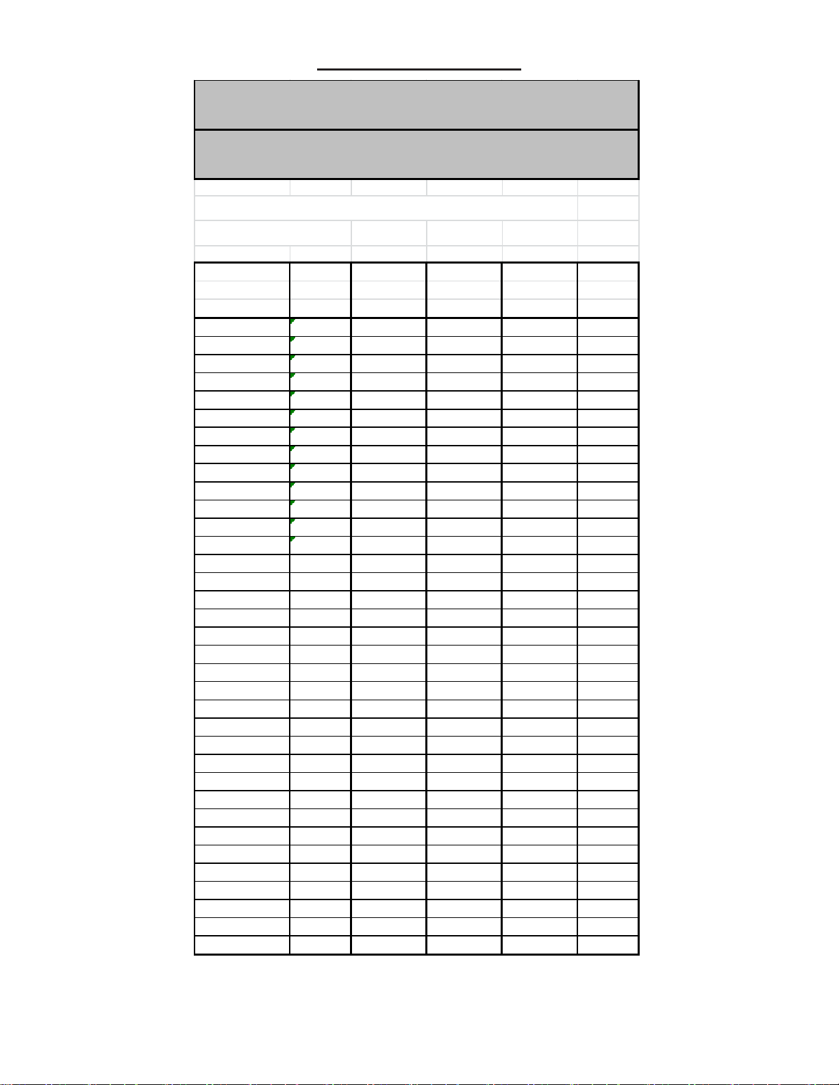
AVAILABLE TOOLING
LARGE PRESS TOOLING
Punc hes and Dies for 127, 129, 130, 150, 230, 231 and 331.
& 134 P ower Presses
Kick & Lever Presses No. 15, 811, 118, 218, 32, 34, 29, 58, 68
TYPE O ROUND PUNCHES AND DIES
Standard Sizes
Fractional,
Dril l or Decimal Punch Part Die P art Set Par t Dea ler
M illimeter Equiv. Number Number Number Code
1/16 .063 300270063 310210063 200270063 T-7
5/64 .078 300270078 310210078 200270078 T-7
3/32-42 DS .094 300270094 310210094 200270094 T-7
40 DS-2.5MM .098 300270098 310210098 200270098 T-7
7/64 .109 300270109 310210109 200270109 T-7
1/8 .125 300270125 310210125 20027012 5 T-7
30 DS .129 300170129 310210129 200270129 T-7
29 DS .136 300270136 310210136 200270136 T-7
9/64-28 DS .141 300270141 310210141 200270141 T-7
5/32 .156 300270156 310210156 200270156 T-7
11/64 .172 30027 01 72 310210 17 2 2002 7017 2 T-7
3/16 .188 300270188 310210188 200270188 T-7
10 DS .194 300270194 310210194 200270194 T-7
13/64 .203 30027 02 03 310210 20 3 2002 7020 3 T-7
7/32 .219 300270219 310210219 200270219 T-7
15/64-A DS .234 300270234 310210234 200270234 T-7
1/4-E DS .250 300270250 310210250 200270250 T-7
17/64-H DS .266 300270266 310210266 200270266 T-7
9/32-K DS .281 300270281 310210281 200270281 T-7
19/64 .297 30027 02 97 310210 29 7 2002 7029 7 T-7
5/16 .313 300270313 310210313 200270313 T-7
21/64 .328 30027 03 28 310210 32 8 2002 7032 8 T-7
11/32 .344 30027 03 44 310210 34 4 2002 7034 4 T-7
23/64 .359 30027 03 59 310210 35 9 2002 7035 9 T-7
3/8 .375 300270375 310210375 20027037 5 T-7
25/64 .391 30027 03 91 310210 39 1 2002 7039 1 T-7
13/32 .406 30027 04 06 310210 40 6 2002 7040 6 T-7
27/64 .422 30027 04 22 310210 42 2 2002 7042 2 T-7
7/16 .438 300270438 310210438 200270438 T-7
29/64-11.5M M .453 300270453 310210453 200270453 T-7
15/32 .469 30027 04 69 310210 46 9 2002 7046 9 T-7
31/64 .484 30027 04 84 310210 48 4 2002 7048 4 T-7
1/2 .500 300270500 310210500 20027050 0 T-7
33/64 .516 30028 05 16 310210 51 6 2002 8051 6 T-7
17/32-13.5M M .531 300280531 310210531 200280531 T-7
- 8 -
Page 9
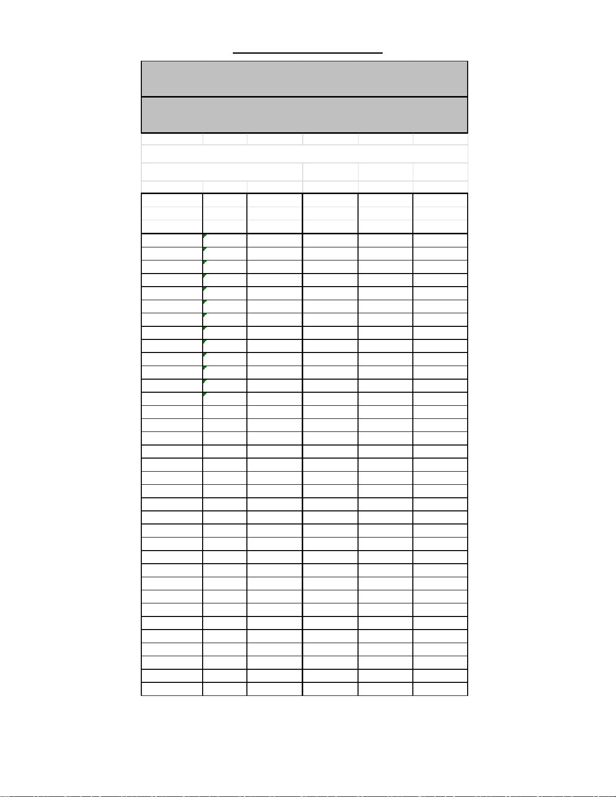
AVAILABLE TOOLING
LARGE PRESS TOOLING
Punches and Di es for 127, 129, 130, 150, 230, 231 and 331.
& 134 P o wer P resses
Ki ck & Lever Pres ses No. 15, 811, 118, 218, 32, 34, 29, 58, 68
TYPE O ROU ND PUNCH E S AN D D IES
Standard Sizes
Fractional,
Drill or Decimal Punch Part Die Part Set Part Dealer
M illimeter Equiv. Number Number Number Code
35/64 .547 300280547 310210547 200280547 T-7
9/16 .563 300280563 310210563 200280563 T-7
37/64 .578 300280578 310210578 200280578 T-7
19/32 .594 300280594 310210594 200280594 T-7
39/64 .609 300280609 310210609 200280609 T-7
5/8 .625 300280625 310210625 200280625 T-7
41/64 .641 300280641 310210641 200280641 T-7
21/32 .656 300280656 310210656 200280656 T-7
43/64 .672 300280672 310210672 200280672 T-7
11/16 .688 300200688 310210688 200280688 T-7
45/64 .703 300280703 310210703 200280703 T-7
23/32 .719 300280719 310210719 200280719 T-7
47/64 .734 300280734 310210734 200280734 T-7
3/4 .750 300280750 310210750 200280750 T-7
49/64 .766 300280766 310210766 200280766 T-7
25/32 .781 300280781 310210781 200280781 T-7
51/64 .797 300280797 310210797 200280797 T-7
13/16 .813 300280813 310210813 200280813 T-7
53/64 .828 300280828 310410828 200280828 T-7
27/32 .844 300280844 310410844 200280844 T-7
55/64 .859 300280859 310410859 200280859 T-7
7/8 .875 300280875 310410875 200280875 T-7
57/64 .891 300280891 310410891 200280891 T-7
29/32-23MM .906 300280906 310410906 200280906 T-7
59/64 .922 300280922 310410922 200280922 T-7
15/16 .938 300280938 310410938 200280938 T-7
61/64 .953 300280953 310410953 200280953 T-7
31/32 .969 300280969 310410969 200280969 T-7
63/64-25MM .984 300280984 310410984 200280984 T-7
1-25.5MM 1.000 300281000 310411000 200281000 T-7
1-1/32 1.031 300281031 310411031 200281031 T-7
1-1/16 1.063 300281063 310411063 200281063 T-7
1-3/32 1.094 300281094 310411094 200281094 T-7
1-1/8 1.125 300281125 310411125 200281125 T-7
1-5/32 1.156 300281156 310411156 200281156 T-7
- 9 -
Page 10
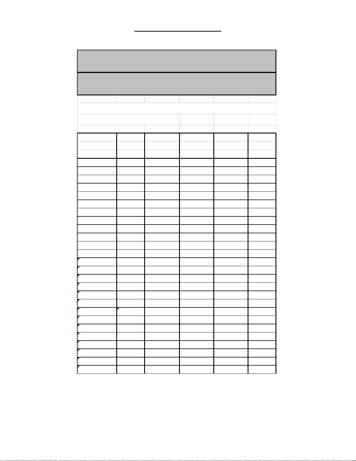
AVAILABLE TOOLING
LARGE PRESS TOOLING
Punc hes and Dies for 127, 129, 130, 150, 230, 231 and 331.
& 134 P ower Pres s es
Kick & Lever Presses No. 15, 811, 118, 218, 32, 34, 29, 58, 68
TYPE O ROUND PU NCHE S A N D D IES
Standard Sizes
Fractional,
Drill or Decimal Punch Part Die Part Set Part Dealer
Millimeter Equiv. Number Number Number Code
1-3/16 1.188 300281188 310411188 200281188 T-7
1-7/32 1.219 300281219 310411219 200281219 T-7
1-1/4 1.250 300281250 310411250 200281250 T-7
1-9/32 1.281 300281281 310411281 200281281 T-7
1-5/16 1.313 300281313 310411313 200281313 T-7
1-11/32 1.344 300281344 310411344 200281344 T-7
1-3/8 1.375 300281375 310411375 200281375 T-7
1-13/32 1.406 300281406 310411406 200281406 T-7
1-7/16 1.438 300281438 310411438 200281438 T-7
1-15/32 1.469 300281469 310311469 200281469 T-7
1-1/2 1.500 300281500 310311500 200281500 T-7
1-17/32 1.531 300281531 310311531 200281531 T-7
1-9/16 1.563 300281563 310311563 200281563 T-7
1-19/32 1.594 300281594 310311594 200281594 T-7
1-5/8 1.625 300281625 310311625 200281625 T-7
1-21/32 1.656 300281656 310311656 200281656 T-7
1-11/16 1.688 300281688 310311688 200281688 T-7
1-23/32 1.719 300281719 310311719 200281719 T-7
1-3/4 1.750 300281750 310311750 200281750 T-7
1-25/32 1.781 300281781 310311781 200281781 T-7
1-13/16 1.813 300281813 310311813 200281813 T-7
1-27/32 1.844 300281844 310311844 200281844 T-7
1-7/8 1.875 300281875 310311875 200281875 T-7
1-29/32 1.906 300281906 310311906 200281906 T-7
1-15/16 1.938 300281938 310311938 200281938 T-7
1-31/32 1.969 300281969 310311969 200281969 T-7
 Loading...