

Roper FES340VW1 Installation Instructions
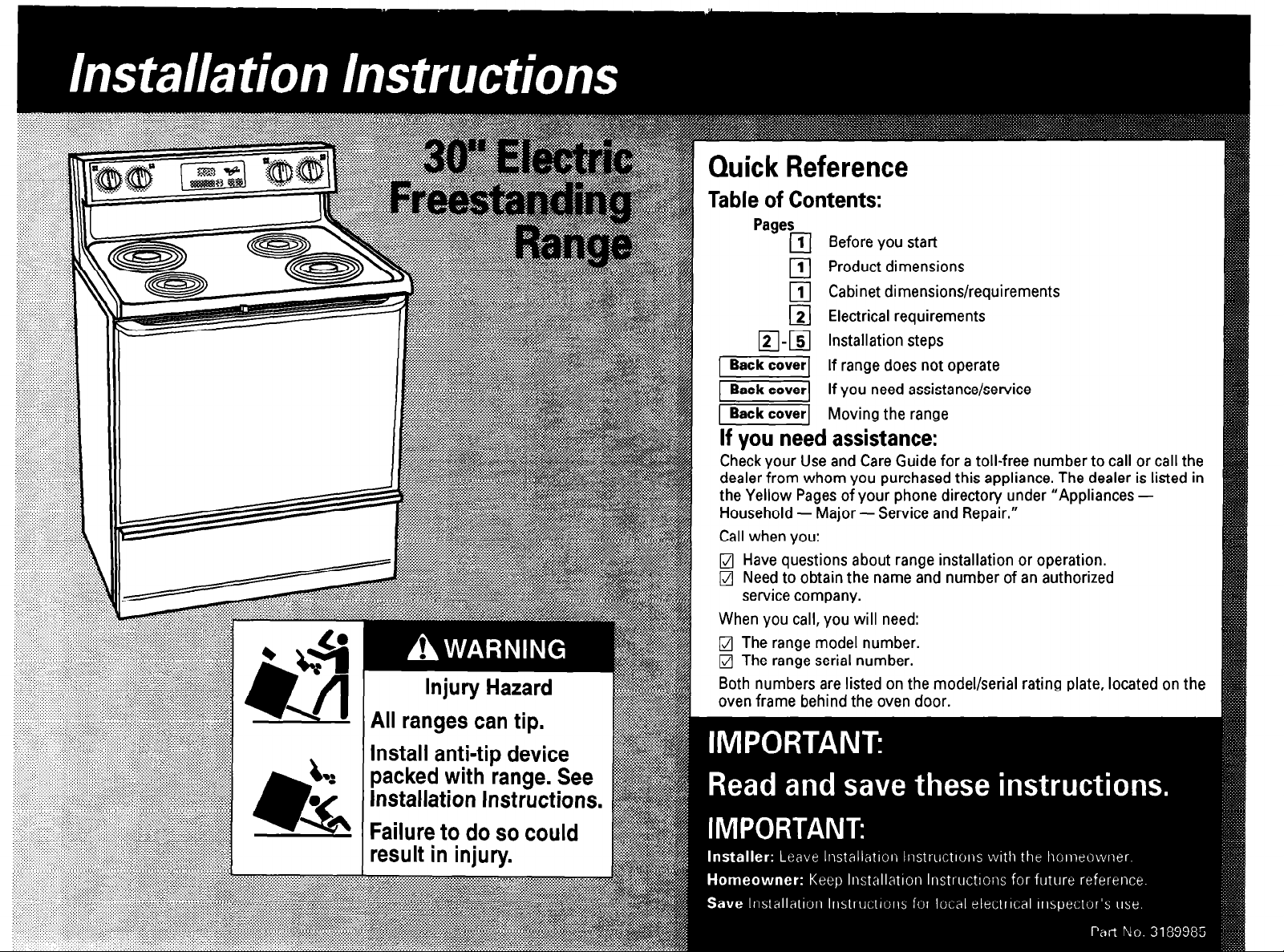
Quick Reference
Table of Contents:
Pages
111 Before you start
Product dimensions
111
111 Cabinet dimensions/requirements
121 Electrical requirements
12-151 Installation steps
[piiaizq
1
Back cover1
I ’
1
Back cover1
Ifd assi&ance,
Check your Use and Care Guide for a toll-free number to call or call the
dealer from whom you purchased this appliance. The dealer is listed in
the Yellow Pages of your phone directory under “Appliances Household - Major
Call when you:
l7J Have questions about range installation or operation.
q
Need to obtain the name and number of an authorized
service company.
When you call, you will need:
q
The range model number.
q
The range serial number.
Both numbers are listed on the model/serial rating plate, located on the
oven frame behind the oven door.
If range does not operate
If vou need assistance/service
Movina the ranae
- Service and Repair.”
Important: Observe all governing codes
and ordinances.
Proper installation is your responsibility. A qualified
technician must install this range. Make sure you
have everything necessary for correct installation. It
is the installer’s responsibility to comply with
installation clearances specified on the model/serial
rating plate. The model/serial rating plate is located
on the oven frame behind the oven door.
Check location where range will be installed. The
range should be located for convenient use in
kitchen.
ALL OPENINGS IN THE WALL OR FLOOR WHERE
RANGE IS TO BE INSTALLED MUST BE SEALED.
Cabinet opening dimensions that are shown must
be used. Given dimensions are minimum
clearances.
Grounded electrical outlet is required. See
“Electrical requirements,” Page 2.
Electrical Shock Hazard
It is the customer’s responsibility to contact
a qualified electrical installer; and to make sure
that the electrical installation is adequate and in
conformance with National Electrical Code,
ANSUNFPA 70 - latest edition*, and all local
codes and ordinances.
Failure to do so could result in death or serious
injury.
Injury Hazard
To eliminate the risk of burns or fire, avoid
installing cabinet storage above the cooking
surface. If cabinets are already installed, reduce
the hazard of reaching over a heated cooking
surface by installing a range hood. The range
hood should extend a minimum of 5 inches out
from the bottom front of the cabinets.
Reaching over a heated cooking surface
could result in a serious burn or other injury.
Mobile home installation
The installation of this range must conform with the
Manufactured Home Construction and Safety
Standard, Title 24 CFR, Part 3280 [formerly the
Federal Standard for Mobile Home Construction
and Safety, Title 24, HUD (Part 28011 or, when such
standard is not applicable, the Standard for
Manufactured Home Installations, ANSI
A225.1/NFPA 501A, or with local codes.
When this range is installed in a mobile home, it
must be secured to the floor during transit. Any
method of securing the range is adequate as long
as it conforms to the standards listed above.
Four-wire power supply cable must be used in a
mobile home installation. The appliance wiring will
need to be revised. See four-wire electrical
connection, Page 3.
Copies of the standards listed may be obtained from:
l
National Fire Protection Association
Batterymarch Park
Quincy, Massachusetts 02269
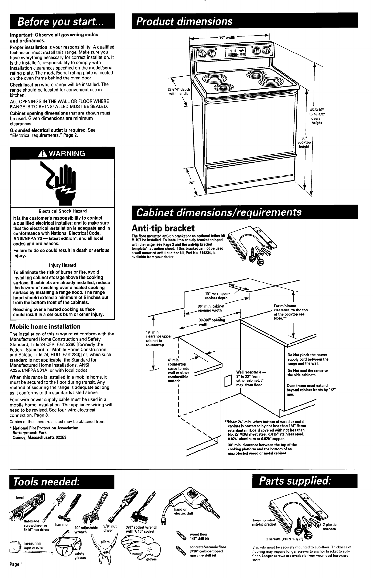
Anti-tip bracket
The floor mounted anti-tip bracket or an optional tether kit
MUST be installed. To install the anti-tip bracket shipped
with the range, see Page 2 and the anti-tip bracket
template/instruction sheet. If this bracket cannot be used,
a wall-mounted anti-tip tether kit, Part No. 814234, is
available from your dealer.
4” min.
! a
countertop
space to side
wall or other
combustible
material
1 p max.fromflo&
ctis by l/2”
For minimum
clearance, to the top
of the
cooktop see
Do Not pinch the power
supply cord between the
range and the wall.
I
Wall receptacle 8” to 22” from
either cabinet. 7”
(1
**Note: 24” min. when bottom of wood or metal
cabinet is protected by not less than l/4” flame
retardant millboard covered with not less than
No. 28 MSG sheet steel, 0.015” stainless steel,
0.024” aluminum or 0.020” copper.
30” min. clearance between the top of the
cooking platform and the bottom of an
unprotected wood or metal cabinet.
Do Not seal the range to
the side cabinets.
Oven frame must extend
I
screwdriver or
5/16” nut driver
r==?%?, measuring
3 tape or ruler
I
Page 1
lu” adjustable
wren nch
P ,. 9
4%
A
’ w -,-
glasses
3/8” nut
driver
3/E” socket wrench
with 7/16” socket
“”
wood floor
l/8” drill bit
concrete/ceramic floor
3/16” carbide-tipped
masonry drill bit
flooring may require longer screws to anchor bracket to subfloor. Longer screws are available from your local hardware
store.
2 screws Ml0 x l-
Brackets must be securely mounted to sub-floor. Thickness of
astic
hors
Power supply cord is not supplied, but is available
through your local electrical supply house.
Electrical Shock Hazard
Electrical ground is required on this appliance.
Do Not ground to a gas pipe.
Do Not change the power supply cord plug. If it
does not fit the outlet, have a proper outlet
installed by a qualified electrician.
Do Not have a fuse in the neutral or grounding
:ircult. A fuse in the neutral or grounding circuit
:ould result in electrical shock.
Do Not use an extension cord with this appliance.
Check with a qualified electrician if you are in
doubt as to whether the appliance is properly
grounded.
Failure to follow these instructions could result in
jeath or serious injury.
If codes permit and a separate grounding wire is
used, it is recommended that a qualified electrician
determine that the grounding path is adequate.
Range must be connected to the proper electrical
voltage and frequency as specified on the model/serial
rating plate. (The model/serial rating plate is found on
the oven frame behind the oven door.)
q
CONNECT WITH COPPER WIRE ONLY.
q
A three-wire or four-wire, single-phase, 120/240volt, 60-Hz, AC-only, electrical supply (or three-wire or
four-wire 120/208-volt if specified on the model/serial
rating plate) is required on a separate, 40-ampere
circuit, fused on both sides of the line.
q
A time-delay fuse or circuit breaker is
recommended.
q
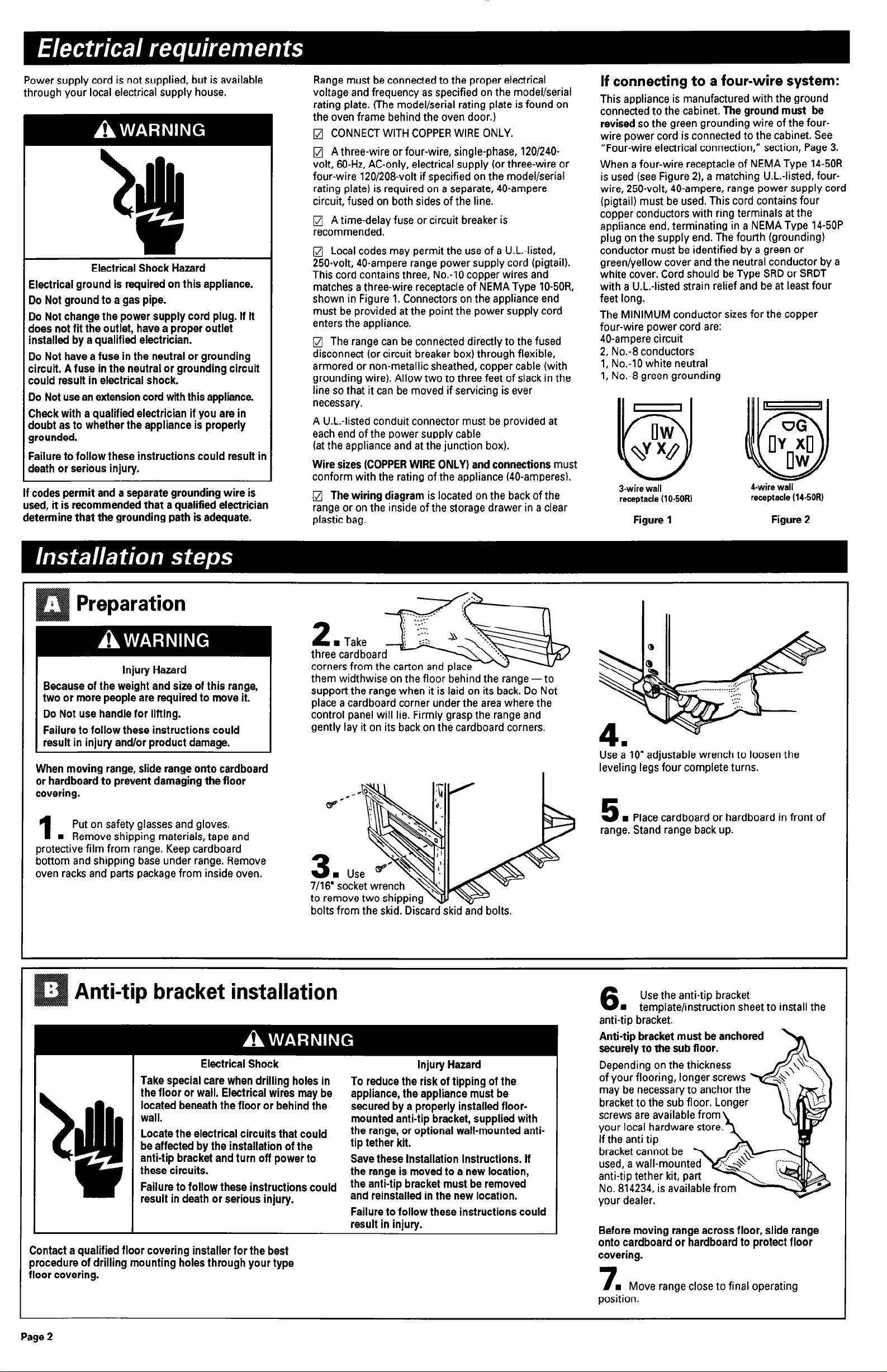
Local codes may permit the use of a U.L.-listed,
250~volt, 40-ampere range power supply cord (pigtail).
This cord contains three, No.-10 copper wires and
matches a three-wire receptacle of NEMA Type IO-50R,
shown in Figure 1. Connectors on the appliance end
must be provided at the point the power supply cord
enters the appliance.
q
The range can be connected directly to the fused
disconnect (or circuit breaker box) through flexible,
armored or non-metallic sheathed, copper cable (with
grounding wire). Allow two to three feet of slack in the
line so that it can be moved if servicing is ever
necessary.
A U.L.-listed conduit connector must be provided at
each end of the power supply cable
(at the appliance and at the junction box).
Wire sizes (COPPER WIRE ONLY) and connections must
conform with the rating of the appliance (40-amperes).
q
The wiring diagram is located on the back of the
range or on the inside of the storage drawer in a clear
plastic bag.
If connecting to a four-wire system:
This appliance is manufactured with the ground
connected to the cabinet. The ground must be
revised so the green grounding wire of the fourwire power cord is connected to the cabinet. See
“Four-wire electrical connection,” section, Page 3.
When a four-wire receptacle of NEMA Type 14-50R
is used (see Figure 21, a matching U.L.-listed, fourwire, 250~volt, 40-ampere, range power supply cord
(pigtail) must be used. This cord contains four
copper conductors with ring terminals at the
appliance end, terminating in a NEMA Type 14-50P
plug on the supply end. The fourth (grounding)
conductor must be identified by a green or
green/yellow cover and the neutral conductor by a
white cover. Cord should be Type SRD or SRDT
with a U.L.-listed strain relief and be at least four
feet long.
The MINIMUM conductor sizes for the copper
four-wire power cord are:
40-ampere circuit
2, No.-8 conductors
1, No.-10 white neutral
1, No.-8 green grounding
3-wire wall
receptacle (lo-50R)
Figure 1
4-wire wall
receptacle (14-50R)
Figure 2
Injury Hazard
Because of the weight and size of this range,
two or more people are required to move it.
Do Not use handle for lifting.
Failure to follow these instructions could
result in injury and/or product damage.
When moving range, slide range onto cardboard
or hardboard to prevent damaging the floor
covering.
Put on safety glasses and gloves.
1
n
Remove shipping materials, tape and
protective film from range. Keep cardboard
bottom and shipping base under range. Remove
oven racks and parts package from inside oven.
them widthwise on the floor behind the range -to
support the range when it is laid on its back. Do Not
place a cardboard corner under the area where the
control panel will lie. Firmly grasp the range and
gently lay it on its back on the cardboard corners.
7/16’ socket wrench
to remove two shippi
bolts from the skid. Drscar
Use : IO’ adjustable wrench to loosen the
leveling legs four complete turns.
w Place cardboard or hardboard in front of
5
range. Stand range back up.
Anti-tip bracket installation
Electrical Shock
Take special care when drilling holes in
the floor or wall. Electrical wires may be
located beneath the floor or behind the
wall.
Locate the electrical circuits that could
be affected by the installation of the
alI
*
Contact a qualified floor covering installer for the best
procedure of drilling mounting holes through your type
floor covering.
anti-tip bracket and turn off power to
these circuits.
Failure to follow these instructions could
result in death or serious injury.
Injury Hazard
To reduce the risk of tipping of the
appliance, the appliance must be
secured by a properly installed floormounted anti-tip bracket, supplied with
the range, or optional wall-mounted antitip tether kit.
Save these Installation Instructions. If
the range is moved to a new location,
the anti-tip bracket must be removed
and reinstalled in the new location.
Failure to follow these instructions could
result in injury.
Use the anti-tip bracket
6
n
template/instruction sheet to install the
anti-tip bracket.
Anti-tip bracket must be anchored
securely to the sub floor.
bracket cannot be
used, a wall-mount
anti-tip tether kit, part
No. 814234, is available from
your dealer.
Before moving range across floor, slide range
onto cardboard or hardboard to protect floor
covering.
7
n
Move range close to final operating
position.
Page 2
 Loading...