

Page 1
Electric Built -in
27” and 24” Single
and Double Ovens
ROPER””
Appliances
IMPORTANT:
Read and save
these instructions.
IMPORTANT:
Installer: Leave Install~ilor~ Instructions with the homeowner,
Homeowner: Keep Inslal!;t!o~~ kstructlonsfor future reference
Save Installation Icstruclions for local electrical inspector’s use.
Page 2
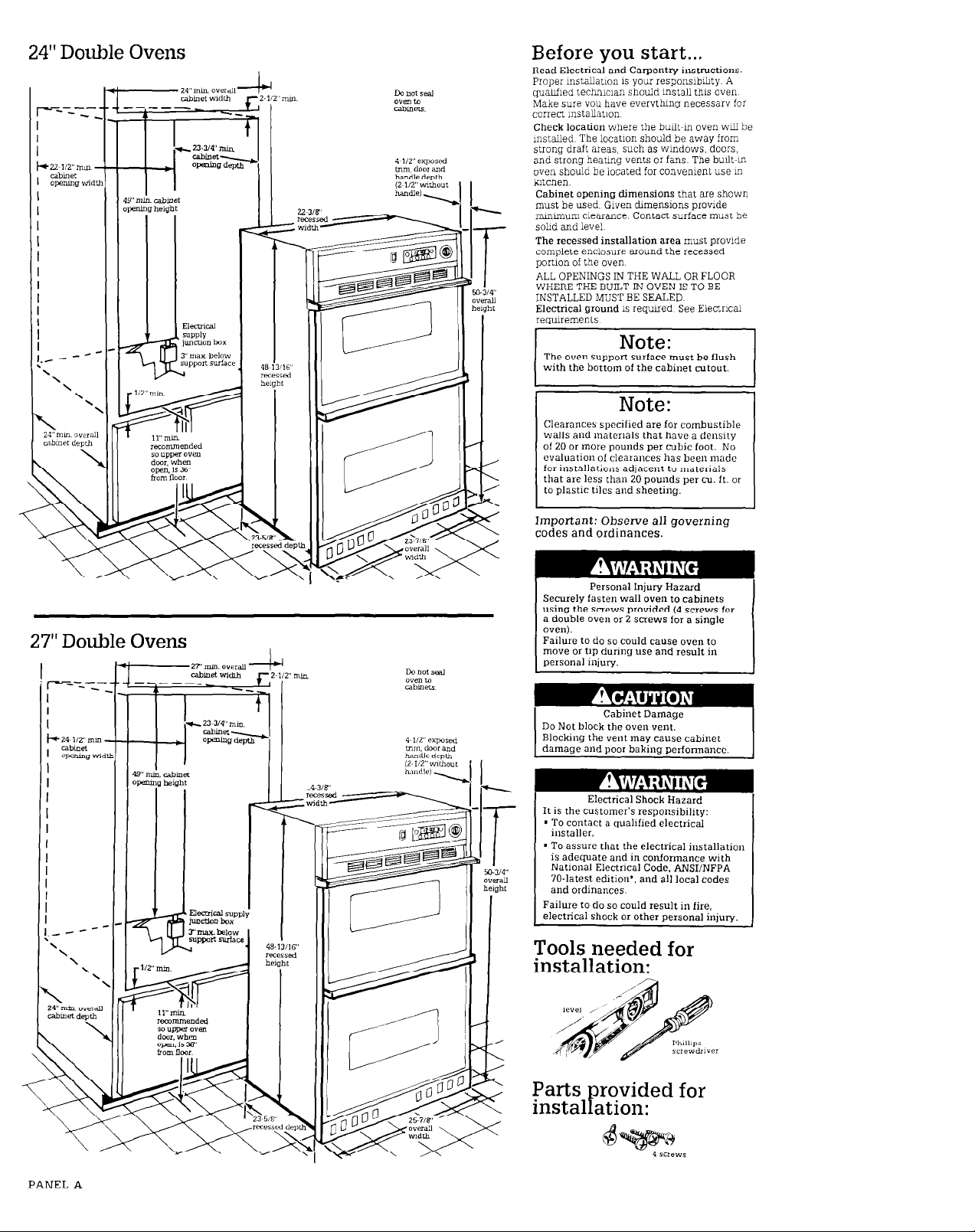
24” Double Ovens
Before you start...
Read Electrical and Carpentry instructions
Proper mstaLlatmn 1s your responslb&y A
quahfled technman should mstall this oven
Make sure you have everythmg necessary for
correct 1nstaUat1on
Check location where the built-m oven wll be
mstalled The locatlon should be away from
strong draft areas, such as wmdows. doors,
and strong heatmg vents 01 fans The built-m
oven should be located for convenient use m
htchen.
Cabinet opening djmensions that are shown
must be used. Given chmenslons provide
mmunum clearance Contact surface must be
sohd and level
The recessed installation area must prowde
complete enclosure around the recessed
ponlon of the oven
ALL OPENINGS IN THE WALL OR FLOOR
WHERE THE BUILT-IN OVEN IS TO BE
INSTALLED MUST BE SEALED
Electrical ground IS required See Electrical
requremenls
The oven suppon surface must be flush
with the bottom of the cabinet cutout.
Note:
Clearances specified are for combustible
walls and materials that have a density
of 20 or more pounds per cubic foot. No
evaluation of clearances has been made
for installations adlacent to materials
that are less than 20 pounds per cu. ft. or
to plastic tiles and sheeting.
27” Double Ovens
Important: Observe all
codes and ordinances.
Personal Injury Hazard
Securely fasten wall oven to cabinets
I
using the screws provided (4 screws for
a double oven or 2 screws for a single
oven).
Failure to do so could cause oven to
move or tip during use and result in
personal injury.
Do Not block the oven vent.
Blocking the vent may cause cabinet
damaqe and uoor bakino Derformancc.
Electrical Shock Hazard
It is the customer’s responsibilrty:
’ To contact a quahhed electrical
~ installer.
’ To assure that the electrical installation
is adequate and in conformance with
National Electrical Code, ANWNFPA
70.latest edition’, and all local codes
and ordinances.
Failure to do so could result in fire,
electrical shock or other personal injury.
governing
Tools needed for
installation:
I
PANEL A
Parts rovided for
instal ation:
f
63
Page 3

24”
Single Ovens
27”
Single Ovens
PANEL B
Page 4

Electrical requirements
Electrical ground is required
on this appliance.
Electrical
connection
Electrical ground is required
on this appliance.
4. Connect the groundmg wue to a
grounded wire 111 the ]unct~on box or to
a grounded, copper cold water Pipe **
Electric Shock Hazard
. Check with a qualified
electrician if you are in doubt as
to whether the appliance is
properly grounded. Improper
connection of the equipmentgrounding conductor line can
result in a risk of electrical
shock.
- Do Not use an extension cord
with this appliance. Such use
may result in a fire. electrical
shock or other personal injury.
* Do Not have a fuse in the neutral
or grounding circuit.
theneutral or grounding circuit
could result in an electrical
shock.
Failure to follow these instruction!
could result in a fire. personal
injury, or electrical shock.
Save Installation Instructions for
the local electrical inspector’s use.
Ths apphance must be
A
n
connected to the proper
electrical voltage and frequency as
specified on the seritiratmg plate
Models rated at 7 0 kw on 240 volts
(5 3 kw on 208 volts) 01 more require a
separate 40.ampere crcuit Models
rated at 3 6 !-xv on 240 volts (2.7 kw
208 volts) or less requne a separate
30.ampere cmxut. Fuse both sides of
the lme A tune-delay [use or cmxt
breaker IS racormmended
OVEN MUST BE CONNECTED
. WI’IH COPPER WIRE ONLY
B
Wire sizes must conform to
C
m the recruements of the
NatIonal Elect&l Code, ANSL+JFPA
70.latest edmon’, and all local codes
and ordumnces for the kilowatt rating
of the oven. This rating can be found
on the serial’ratmg plate behmd the
oven door on the front frame.
This apphance should be
D
9 connected to th.e fused
chsconma (or Cmxt breaker) box
through flexible armored or
non-metalhc, sheathed copper cable
fwlth aroundma wre) The flexible
&m&d cable &ten&g from the
apphance should be connected duectly
lo the junction box
Locate the lunctlon box to
. aLlow as much slack in the
E
cable as possible between the
lunctlon box and the apphance so that
the oven can be moved ti servlcmg is
ever needed
A U.L -hsted condux connector
must be provided at the
F
’ ~unctlon box
It 1s tte personal
G
n
responsiblbty and obhgation
of the customer to contact a quahfled
elennclan to assure that the klectrical
mstallatmn IS adequate and is m
conformance with the National
E!ectncal Code ANSI/NFPA 70.latest
edItIon*, and aL’local codes and
ordmmces
A fuse in
on
Electrical Shock Hazard
- Do Not connect appliance to
electrical supply until appliance
is permanently grounded.
l
Disconnect power to the
junction box before making the
electrical connection.
n
This appliance must to
connected to a grounded.
metallic. permanent wiring
system, or a grounding
conductor should be connected
to the grounding terminal of
lead on the appliance.
Failure to follow these
jnstructions could result m a fire.
I
personal injury, or electrical
shock.
I
Tbs apphance 1s manufactured wxh
white (neutral) power supply wre and
a cabmet-connected. green groundmg
wre (green twisted together)
Connect the apphance cable to the
lunctmn box through the U L -hsted
conduit connector. Complete
electrical connection accordmg to your
mstallatmn needs
A. Where local codes
permit...
connecting the cabinet-grounding
conductor to the neutral (white)
junction box wire:
Figure 1
1. Turn power supply off
2. Connect three wires green and
whte apphance cable wLies with the
neutral (wtite) wne m junction box
3. Connect the two black wues
together, then the two red wues
together (See Figure 1 )
B. Where local codes
DO NOT permit...
connecting the cabinet-grounding
conductor to the neutral (white)
junctmn box wire:
Figure 3
5. A separate copper groundmg wxe
(No. 10 mmmum) MUST be connected
to a grounded metal cold water pipe by
means of a clamp and then to the
external groundmg mnnector screw.
Do Not ground to a gas
or hot water pipe. Do Not connect
to electrical supply until appliance 1s
permanently grounded. (See
Figure 3 )
supply
pipe
C. IF connecting to a
four-wire electrical
system...
DO NOT connect the cabinetgrounding conductor to the neutral
(white) junction box wire.
Figure 4
1. Turn power supply off
2. Separate the green and wtite
appbance cable wues
3. Connect the white apphance cable
wue to the neutral (wtite) wre m
iuncilon box
4. Connect the two black wires
tooether. then the two red wres
together (See Figure 4.)
5. Connect the green apphance cable
wre to green groundmg wxe in the
]unctlon box
A wrong dagram is mcluded
H
m m the Tech sheet. The Tech
sheet 1s located oehmd the control
panel
PANEL C
1. Turn power suppiy off
2. Connect the white apphance cable
wue to the neutral (whxe) wue m
]unctlon box
3. Connect the two black wres
together; then the two red wnes
together (See Figure 2 )
Figure 2
Page 5

Now start...
With oven in kitchen.
Re.nove stippmg materials,,
1
m tape and protectwe film from
wall oven. Do NoI remove the foam
shipping base at this time.
Remove racks and other parts
2
n
from mslde oven. Remove the
au grille taped to the top OI side
of oven
Personal Injury/Product Damage
’ Use both hands to remove oven
doors.
’ Grasp only the sides of rhe oven
door. Do Not use any portion 01
the lronr lrames or trim for
lifting.
Failure to properly grasp oven
door could result in damage fo
product or personal injury.
._
Close lower oven door LO the
n
broil posltlon Grasp the sides
4
of the oven door and pull the door up
and out of hmge slots to remove
door aslde
Repeat Steps 3 and 4 for upper
. oven door
5
Set
Turn power supply off Move
. oven close to final posmon
6
Remove and dmard foam shlppmg
base. Feed apphaace cable through
opemng m cabmet. Make electrical
conmxt~om See Electrical
remurements and Electrical
connection sectlom, Panel B.
Product Damage
Carefully push against seal area of
the front frame when pushing
oven into cabinet. Do Not push
against ourside
Failure to follow this instruction
can result in damage to the
porcelain finish.
edges.
Complerely o*en lower oven
3
n
door Remove the two oven
door mews (Not all models have
oven door screws )
6
Floor Damaae
6.
PANEL D
Numbers
correspond
to steps.
Page 6

Personal Injury/Product Damage
Securely fasten oven to cabinets
using the four screws provided.
Failure to
oven to move or tip during use
and result in
product damage.
8
n
screws for a double oven) through the
mountmg holes m the front frame of
the oven to secure the oven to the
cabmet Do Not overtlghten screws
. three sxews provided.
9
do
so could cause the
personal injury or
Center oven mto cabmet
cutout Use two screws (four
3°C
-b
InstaU lower air grille usmg the
“se the one.
low prollle screw
in ml Posltmn
Check the operation of the
n
11
Push ‘Bake’ button. ‘- _ _ “F” will appear
m the dxplay and the “Bake” hght will
come on. Press “Bake” button until 350°F
appears m the &splay The bottom and
uoper. outer elements should alow red
The upper (or smgle) oven ‘on”mdlcator
hght should be on and the oven should
be heatma. Push the cancel button The
tnne of day should appear III the display.
Check the operation of the lower oven.
Set the lower oven control knob to
350°F The bottom and upper, outer
elements should glow red The lower
oven mdlcator haht should be on and
the oven shouldbe heatmg Turn the
control knob to “OFF”
12
element. Push the “Broil” bu!ton “_ _ -”
will appear m the display and tne “Broil’
uxhcator hghr wLLl come on Turn oven
control knob until “HI Broil aDoears m the
&splay Both lop elemerlts sh&ld glow
red The upper (or smg;e) oven “On”
mdlcator hght should be on and the oven
should be hentmo Push the cancel button
The time of day should appear m the
dlsp1ay
Check the weration of the lower oven
Set the low& oven 10m;)2:i.tu1e ConlTol
k11ob to ‘Broil” The top, !m:er elements
should
huh1 should be on
upper (01 single) oven.
Check the operation of the
l
upper (or single) oven broil
QlOW
red The lower ovci, mdxator
and
the oven should be
10
pW.laLly flttmg the door hinges mto the
hmge slots FuLl door shghtly toward
you, then shde door completely m place
Remstall the two oven~door screws (lf
rec;ured for your oven door) If door does
not close, you have not pushed hmges
complete!y ml0 frame Repeat for lower
oven door Turn power supply on
Replace the oven racks
. Replace upper oven door by
Congratulations!
You have just finished
installing your II~W.
Roper oven. Keep Installation
Instructions available for
easy reference.
PANEL E
 Loading...