

Roper C340 Owner's Manual
I
1
-. -
/’
‘-~
r.
i;
CONTENTS
INSTALLATION
USE AND CARE
Important Instructions for Your Safety
Your Counter Unit and Its Features
Using Your Counter Unit
Favorite American Recipes
Cleaning lips
Removable Control Knobs
SERVICE
What To Do Before Calling For Service
WARRANTY
ECrnll
INSTALLATION
IMPORTANT: Save these instruction for the local electrical inspector’s use.
TOOL LIST
The following tools are needed to install your new counter unit.
0%” drill bit
*Electric or hand drill
*Flat bladed screwdriver
@Pencil
*Ruler or tape measure and straight edge
#Hand saw or sabre saw
LOCATION
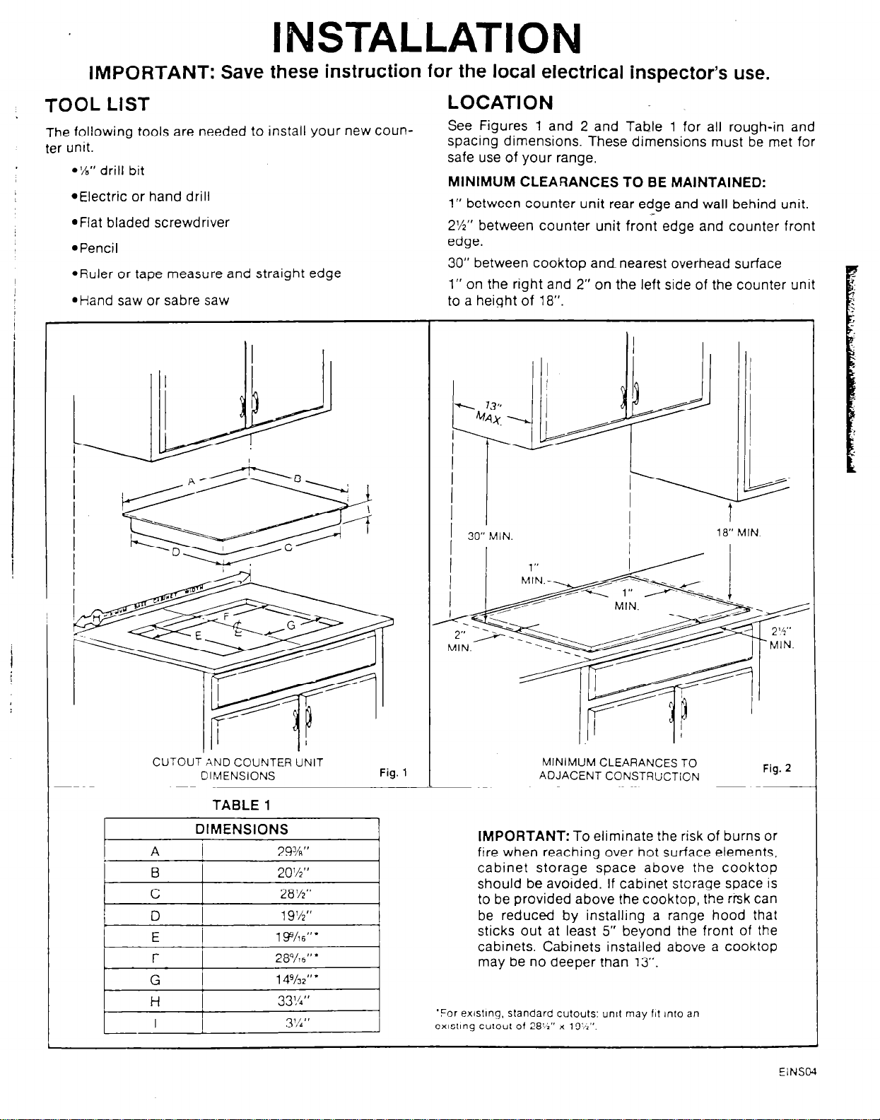
See Figures 1 and 2 and Table 1 for all rough-in and
spacing dimensions. These dimensions must be met for
safe use of your range.
MINIMUM CLEARANCES TO BE MAINTAINED:
1” between counter unit rear edge and wall behind unit.
2%” between counter unit front edge and counter front
edge.
30” between cooktop and nearest overhead surface
1” on the right and 2” on the left side of the counter unit
to a height of 18”
CUTOUT AND COUNTER UNIT MINIMUM CLEARANCES TO
L
DIMENSIONS
TABLE
DIMENSIONS
1
29%”
20%”
28%”
19%”
1 Y/16”’
28g/r6”’
14%2”
33’A”
3 % ’ ’
Fig. 1
ADJACENT CONSTRUCTION
IMPORTANT:
fire when reaching over hot surface elements,
cabinet storage space above the cooktop
should be avoided. If cabinet storage space is
to be provided above the cooktop, the rrsk can
be reduced by installing a range hood that
sticks out at least 5” beyond the front of the
cabinets. Cabinets installed above a cooktop
may be no deeper than 13”.
‘For ex~stlng, standard cutou1s: unll may 111 Into an
exlstlng cutout of 28%” x 19’h”.
To eliminate the risk of burns or
Fig. 2
EiNSC4
INSTALLATION
We recommend that you have the electrical hookuo of
your counter unit done by a qualified electrician. Have
the electrician show you where your disconnect is
located.
The electrical power to the range supply line must be
shut off while line connectlons are belng made. Failure to
do so could result In serlous InJury or death.
When making the wire connections, use the entire length ’
of conduit provided (3 ft). The conduit must not be cut.
Call your Electric Company and ask which codes apply
in your area. If there are no codes, you must follow the
NATIONAL ELECTRICAL CODE, ANSI/NFPA NO. 70-
1987. You can get a copy by writing:
National Fire Protection Association
Batterymarch Park
Quincy, MA 02269
I
If you fail to wire your counter unit in accordance with
governing codes, you may create a hazardous condition.
I
You must use a three-wire, single-phase AC 120/240 Volt
or 208Y/120 Volt, 60 Hertz electrical system.
Use a minimum wire size of No. 10 copper wire protected
with a 30 Amp. fuse or circuit breaker for both 208Y/120
Volt and 120/240 Volt electrical systems,
Do not use aluminum wiring to connect your counter unit
to the household circuit.
Before installing the counter unit or moving it to another
location, have the electrician verify:
l That your home is provided with adequate electrical
service.
Connect the red and black leads from the counter unit
conduit to the corresponding leads in the junction box.
The bare ground wire in the conduit is connected to the
counter unit frame. Connect the other end of this wire to
a properly grounded cold water pipe or use another
approved grounding method.
A white (neutral) wire is not needed for this unit. The
white lead from the household electrical supply can be
taped and terminated in the junction box.
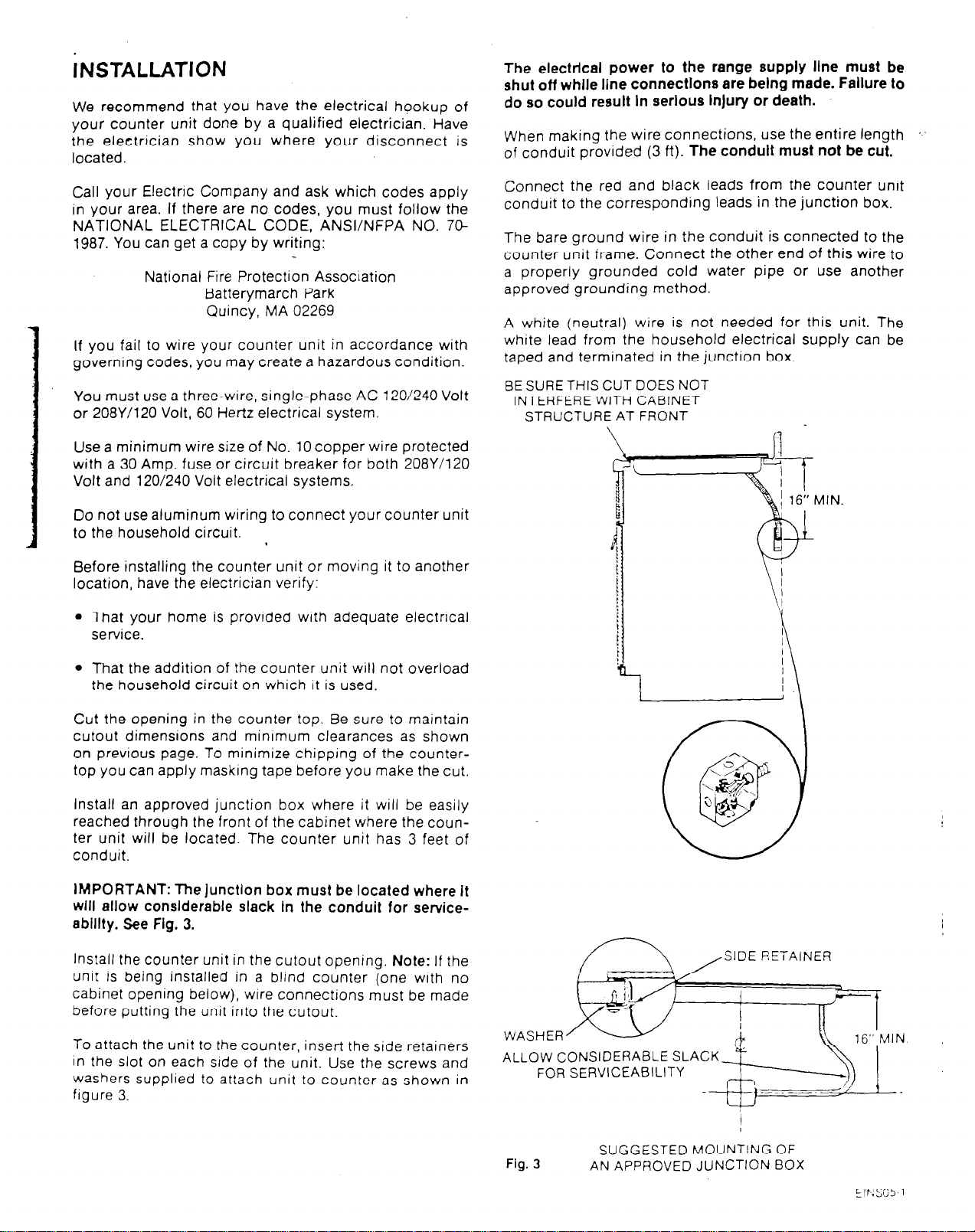
BE SURE THIS CUT DOES NOT
INTERFERE WITH CABINET
STRUCTURE AT FRONT
MIN.
l That the addition of the counter unit will not overload
the household circuit on which it is used.
Cut the opening in the counter top. Be sure to maintain
cutout dimensions and minrmum clearances as shown
on previous page. To minimize chipping of the countertop you can apply maskrng tape before you make the cut.
Install an approved junction box where it will be easily
reached through the front of the cabinet where the counter unit will be located. The counter unit has 3 feet of
conduit.
IMPORTANT: The junction box must be located where It
will allow conslderable slack In the conduit for service-
eblllty. See Fig. 3.
Install the counter unit in the cutout opening. Note: If the
unit is being installed in a blind counter (one with no
cabinet opening below), wire connections must be made
before putting the unit into the cutout.
To attach the unit to the counter, insert the side retainers
in the slot on each stde of the unit. Use the screws and
washers supplied to attach unit to counter as shown in
figure 3.
SIDE RETAINER
Fig. 3
SUGGESTED MOUNTING OF
AN APPROVED JUNCTION BOX
 Loading...