

Roper B400 Use And Care Manual
USE and CARE MANUAL
GAS BUILT-IN
model B400
INSTALLATION
l
I I
I 1
IIIllII IIIII)I )IIIIII
4356235 (343754-l )

THIS PAGE

FOR YOUR SAFETY
If you smell gas:
1. Open windows.
2. Don’t touch electrical switches.
3. Extinguish any open flame.
4.
Immediately call your gas supplier
FOR YOUR SAFETY
Do not store or use gasoline or other
flammable vapors and liquids in the
vicinity of this or any other appliance.
L.P. Burner Adjustments
The adjustments in the Installation Section must be
made before you try to use your oven.
If you are using Liquified Petroleum Gas (bottled
gas) all L.P. adjustments in the Installation Section
must be made before use.
If your oven is not properly adjusted, flames may be
too high, or the oven may use too much fuel, release
toxic fumes or cook poorly.
WARNING: Improper
installation,
alteration, service or maintenance can cause in-
jury or property damage. Refertothismanual. For assistance or
additional information
consult a qualified
installer,
service
agency, manufacturer
(dealer) or the gas
supplier.
GNOTOB-1
NOTICES
INSTALLATION
USE AND CARE
Important Instructions for Your Safety
Your Oven and Its Features
Burner Ignition
Oven Cooking
Broiling
Favorite American Recipes
Continuous-Cleaning Oven Finish(only on selected models)
Cleaning Tips
Removable Oven Parts
SERVICE
Replacing Oven Light Bulb
What to Do before Calling for Service
Adjusting Oven Temperature
WARRANTY
GCOOl9
INSTALLATION
INSTALLER:
Leave these instructions with the
OWNER: Keep these instructions for future
appliance.
US.
TOOL LIST
1.
1 i8”drill bil
2. Electric or hand drill
3. Flat bladed screwdriver
4. No. 1 or No. 2 Phillips screwdriver
5. Pencil
6. Ruler and straight edge
7. Hand saw or saber saw
8. Pipe wrench
9. 5/8” wrench and l/2” wrench or adjustable wrench
10.
Pliers
LOCATION
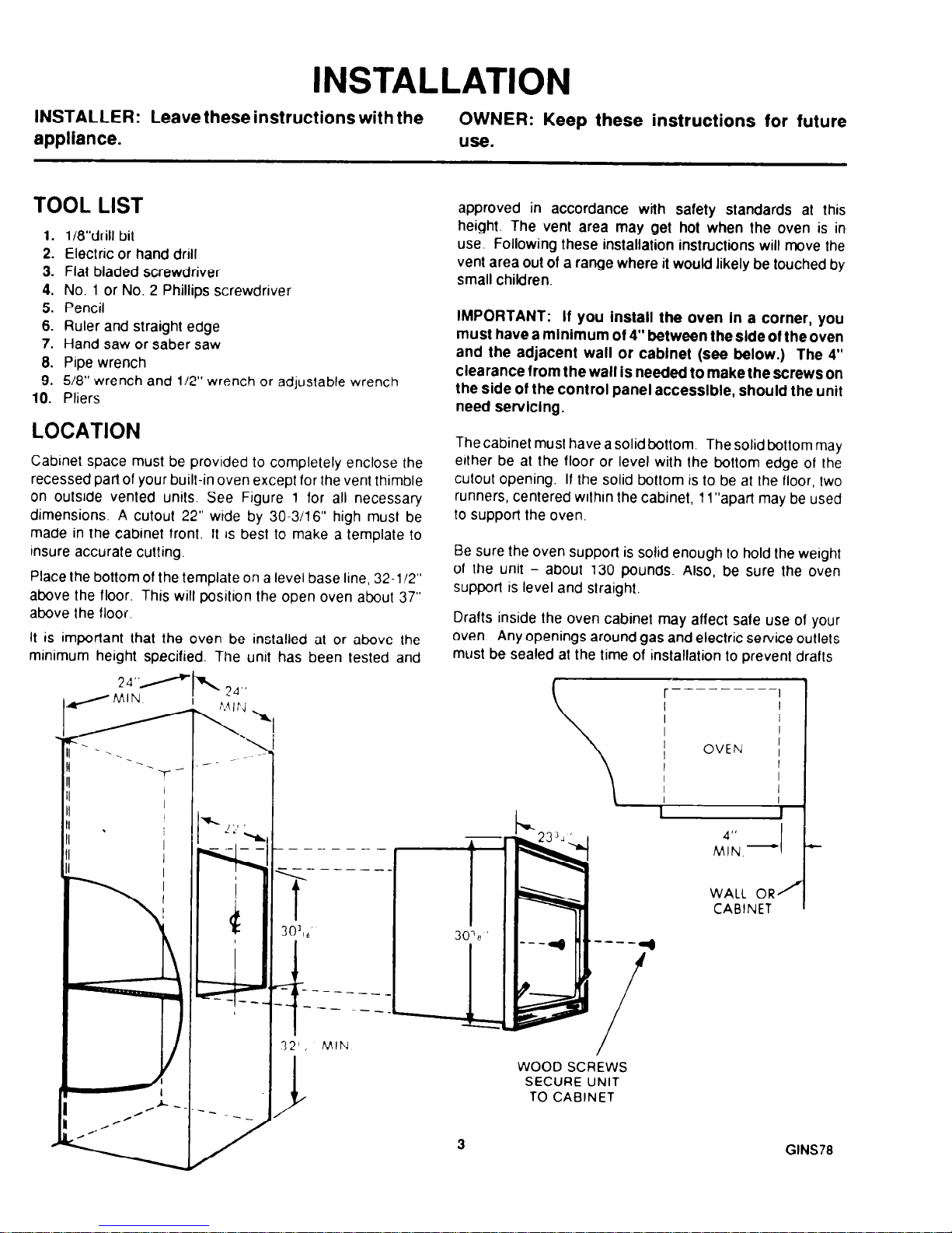
Cabinet space must be provided to completely enclose the
recessed part of your built-in oven except for the vent thimble
on outside vented units. See Figure 1 for all necessary
dimensions. A cutout 22” wide by 30.3/16” high must be
made in the cabinet front. It IS best to make a template to
insure accurate cutting.
Place the bottom of the template on a level base line, 32-112”
above the floor. This will position the open oven about 37”
above the floor.
It is important lhat the oven be installed at or above the
mlnlmum height specified. The unit has been tested and
24-A
{M’N
v 24”
approved in accordance with safety standards at this
height. The vent area may get hot when the oven is in
use. Following these installation instructions will move the
vent area out of a range where it would likely be touched by
small children.
IMPORTANT: If you install the oven In a corner, you
must have a minimum of 4” between the side of the oven
and the adjacent wall or cabinet (see below.) The 4”
clearance from the wall is needed to make the screws on
the side of the control panel accessible, should the unit
need
servicing.
The cabinet must have a solid bottom. The solid bottom may
either be at the floor or level with the bottom edge of the
cutout opening. If the solid bottom is to be at the floor, two
runners, centered within the cabinet, 1l”apart may be used
to support the oven.
Be sure the oven support is solid enough to hold the weight
of the unit - about 130 pounds. Also, be sure the oven
supporl is level and straight.
Drafts inside the oven cabinet may affect safe use of your
oven. Any openings around gas and electric service outlets
must be sealed at the time of installation to prevent drafts
r----
----I
I
I
OVEN
-rjfy &,-I
WALL OR/
CABINET
3
WOOD SCREWS
SECURE UNIT
TO CABINET
C
GINS78
ELECTRICAL CONNECTIONS
Check with your local utilities for electrical codes that apply
in your area If there are no local codes, Ihe National
Electrical Code, ANSI/NFPA No. 70-1987 must be followed
You can get a copy by wnting
National Fire ProtectIon Association
Batterymarch Park
Oulncy, MA 02269
An adequate electrical supply and outlet must be used to
operate the electrical parts of your oven The oven cord has
a ‘three prong plug and must be used with a properly
grounded three hole outlet with standard 120 volt 60 Hertz
AC household current.
Install the electrical outlet below the oven on the right side
It should be easily reached through cabinet doors below the
oven See Figure 5
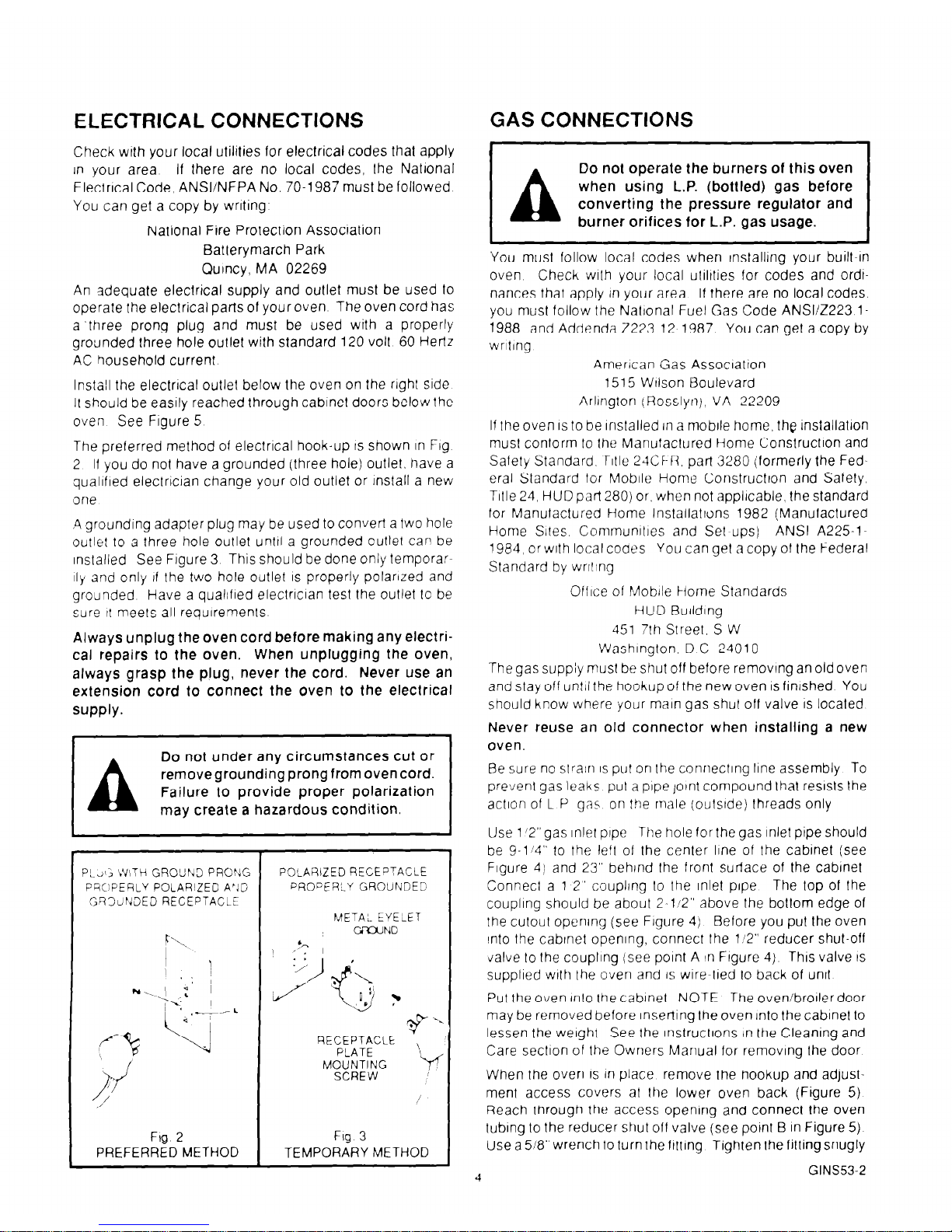
The preferred method of electrlcal hook-up IS shown In Fig
2 Ii you do not have a grounded (three hole) outlet, have a
qualified electrician change your old outlet or Install a new
lone
.4 grounding adapter plug may be used to convert a two hole
outlet to a three hole outlet until a grounded outlet can be
installed See Figure 3 This should be done only temporarsly and only
11
the two hole outlet
IS
properly polarized and
grounded Have a quaIlfled electrician test the outlet to be
sure it meets all requirements
Always unplug the oven cord before making any electrical repairs to the oven. When unplugging the oven,
always grasp the plug, never the cord. Never use an
extension cord to connect the oven to the electrical
supply.
A
Do not under any circumstances cut or
removegrounding prong from oven cord.
Failure to provide proper polarization
may create a hazardous condition.
P!~.J(; ~YITH GROUND PRONG
PG:)PERLY POLARIZED A’lG
GR3clNDED RECEPTACLE
POLARIZED RECEPTACLE
PROPERLY GROUNDED
METAL EYELEl
CiFWND
RECEPTACLE
PLATE
MOUNTING
SCREW
Fig. 2
Fig 3
PREFERRED METHOD TEMPORARY METHOD
GAS CONNECTIONS
Do not operate the burners of this oven
burner orifices for L.P. gas usage.
You must follow local codes when InstallIng your built-in
oven Check with your local utiltties for codes and ordtnances that apply in your area If there are no local codes.
you must follow the Natlonal Fuel
Gas
Code ANSI/Z223 l-
1988 and Addenda 2223
12
1987 You can get a copy by
wrltlng
American Gas Association
1515 Wilson Boulevard
Arlington (Rosslyn), VA 22209
If the oven IS to be Installed In a mobile home, the lnstallatlon
musl conform to the MdnufaClured Home Construction and
Safety Standard, Title 24CF-R part 3280 (formerly the Federal Standard for Mobile Home Construction and Safety,
Title 24, HUD part 280) or, when not applicable, the standard
for Manufactured Home Installations 1982 (Manufactured
Home Sites. Communitres and Set-ups) ANSI A225l1984, or with local cooes You can get a copy of the Federal
Standard by wrlllng
Ofllce of Mobile Home Standards
tHUD BulldIng
451 7th Street, S W
Washington. D C 24010
The gas suppiy must be shut off before removing an old oven
and stay off until the hookup of the new oven is finished
You
should know where your main gas shut off valve
IS
located
N.ever reuse an old connector when installing a new
oven.
Be sure no stralri
IS
put on the connecting line assembly To
prevent gas leaks put a pipe joint compound that resists the
action of L P gas on the male (outstde) lhreads only
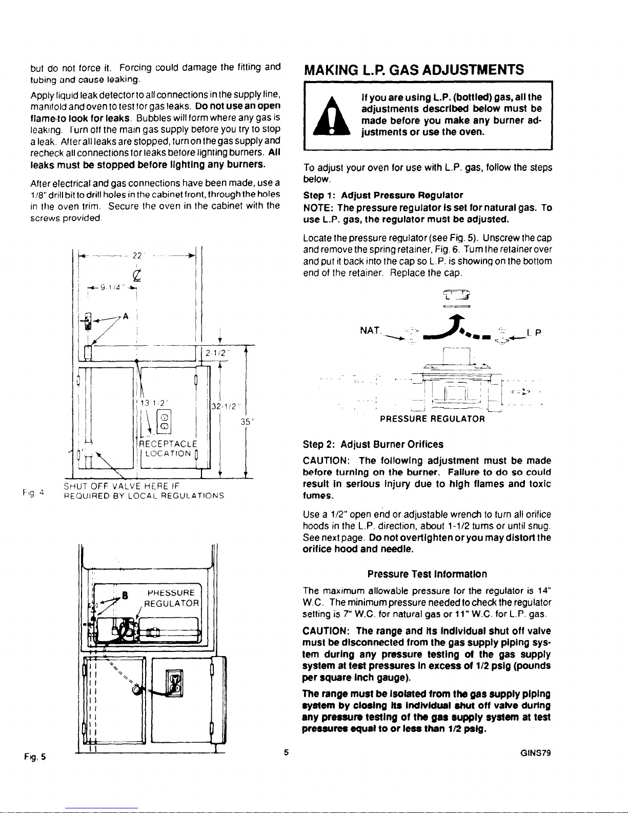
Use 1 ‘2”gas inlet pope The hole for the gas inlet pipe should
be g-114” to the left of the center line of the cabinet (see
Figure 4) and 23” behlnd the front surface of the cabinet
Connect a 1 2” coupling to the Inlet pipe
The top of the
coupling should be about 2-1’2” above the bottom edge of
the cutout opening (see Figure 4) Before you put the oven
into the cabinet opening, connect the 112” reducer shut-off
Jalve to the coupling (see point A In Figure 4)
This valve IS
supplied wllh the oven and IS wire-tied to back of unit
Put the oven lnlo lhe cabinet NOTE The oven/brollerdoor
may be removed before Inserting the oven Into the cabinet to
lessen the weight See the inslructlons tn the Cleaning and
Care section of the Owners Manual for removing Ihe door
When the oven
IS
In place remove the hookup and adjuslment access covers at the lower oven back (Figure 5)
Reach lhrough the access opening and connect the oven
tubing to the reducer shut off valve (see point B in Figure 5)
Use a 518” wrench to turn the ftttlng Tighten the fitting snugly
4
GINS532
but do not force it, Forcing could damage the fitting and
tubing and cause leaking.
Apply liquid leak detector to all connections in the supply line,
manifold and oven to test tor gas leaks. Do
not use an open
flameto look
for leaks.
Bubbles will form where any gas is
leaking. Turn off the main gas supply before you try to stop
a leak. After all leaks are stopped, turn on the gas supply and
recheck all connections for leaks before lighting burners. All
leaks must be stopped before llghtlng any burners.
After electrical and gas connections have been made, use a
1!8”drill bit to drill holes in the cabinet front, through the holes
in the oven trim. Secure the oven in the cabinet with the
screws provided
Fig 4
&UT OFF VALVE HERE IF
BEQUIRED BY LOCAL REGULATIONS
1 II
1
Fg. 5
MAKING L.P. GAS ADJUSTMENTS
A
If you are using L.P. (bottled) gas, all the
adjustments described below must be
made before you make any burner ad-
justments or use the oven.
To adjust your oven for use with L.P.
gas,
follow the steps
below.
Step 1: Adjust Pressure Regulator
NOTE: The pressure regulator Is set for natural gas. To
use L.P. gas, the regulator must be adjusted.
Locate the pressure regulator (see Fig. 5). Unscrew the cap
and remove the spring retainer, Fig. 6. Turn the retainer over
and put it back into the cap so L-P. is showing on the bottom
end of the retainer. Replace the cap.
I *
--i
PRESSURE REGULATOR
Step 2: Adjust Burner Orifices
CAUTION: The following adjustment must be made
before turnlng on the burner. Failure to do so could
result in serious Injury due to high flames and toxic
fumes.
Use a l/2” open end or adjustable wrench to turn all orifice
hoods in the L.P. direction, about l-1/2 turns or until snug.
See
next page.
Do not overtlghten or you may distort the
orifice hood and needle.
Pressure Test Information
The maximum allowable pressure for the regulator is 14”
W.C. The minimum pressure needed to check the regulator
setting is 7” W.C. for natural
gas or
11” W.C. for L.P. gas.
CAUTION: The range and lts lndlvldual shut off valve
must be dlsconnected from the gas supply plplng system during any pressure testlng ot the gas supply
system at test pressures In excess of l/2 psig (pounds
per square Inch gauge).
The range must be Isolated irom the gas supply plping
system by closing its lndlvldual
shut
off valve during
any pressure testlng of the gas supply system at test
pressures equal to or less than l/2 psig.
5
GINS79
MAKING BURNER ADJUSTMENTS
If you are using L.P. (bottled) gas, all the
adjustments described on the previous
pagemust bemadebeforeyoumakeany
burner adjustments or use the oven.
All ovens are factory adjusted for use with the natural gas
used in most
areas. But, since the gas in
some
areas may
be different, you should check all adjustments described
below.
If youare using L.P. gas, all theadjustments must
be made.
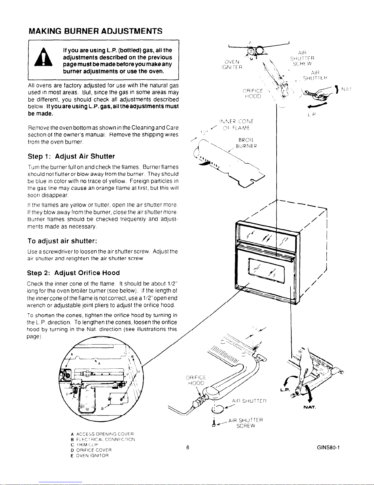
Remove the oven bottom as shown in the Cleaning and Care
section of the owner’s manual. Remove the shipping wires
from the oven burner.
Step 1: Adjust Air Shutter
Turn the burner full on and check the flames. Burner flames
should not flutter or blow away from the burner. They should
be blue in color with no trace of yellow. Foreign particles in
the gas line may cause an orange flame at first, but this will
soon disappear.
If the flames are yellow or flutter, open the arr shutter more
If they blow away from the burner, close the air shutter more
Burner flames should be checked frequently and adjustments made as necessary
To adjust air shutter:
Use a screwdriver to loosen the air shutter screw. Adjust the
air snutter and retrghten the air shutter screw.
Step 2: Adjust Orifice Hood
Check the inner cone of the flame. It should be about 112”
long for the oven broiler burner (see below). If the length of
the inner cone of the flame is not correct, use a li2”open end
6
GINS80-1
‘r\
BROll
To shorten the cones, tighten the orifice hood by turning in
the L.P. direction. To lengthen the cones, loosen the orifice
hood by turning in the
n (see illustrations this
AIR SHUTTER
AIR SHUTTER
A ACCESS OPENING COVER
B FI FCTRICAL CONNFCTION
C TRIM CLIP
D ORIFICE COVER
E OVEN IGNITOR
NAT.
 Loading...